1. Aircraft Integrated Research Vehicle Optimal Loading Test-Stand (AIRVOLT)
NASA CIPAIR PROGRAM
Christopher Ray Ramirez
College of the Desert, Palm Desert, California 92260
Phone: (760) 346-8041, FAX: (760) 773-2570, E-mail: christopher.ramirez@live.com
Overview
AIRVOLT is an electric propulsion system project whose purpose is to obtain critical design measurements; these
include thrust, torque, RPM, temperature, noise, air speed, power, and efficiencies which include the battery, motor
controller, and final propeller. In addition AIRVOLT extends these design characteristics to larger scales of
complexity. The National Instruments (NI) LabVIEW software development package is used to conduct multi-platform
tests for three unique test stands. The first test stand (MiniVOLT) investigates the hardware and software setup on a
small scale and provide a basis for the other two more complex stands (MediVOLT and MaxiVOLT). In addition to
software and hardware concerns, safety is a key design goal of this project. Design of safety procedures for
personnel, the software, and hardware system has been demonstrated. This work describes progress for the
MiniVOLT and MediVOLT test beds; a description of the hardware, software, and design safety components of the
project.
Motor Controller
AC Motor Curtis Controller 1238-7501: The Curtis AC induction motor controllers deliver smooth power and
provides unique adaptability and power through addition of a programmable logic controller embedded in a
modern motor controller. It offers an advanced Pulse Width Modulation technology for efficient use of battery
voltage, low torque waves, low motor harmonics, and minimized switching losses.
Lithium-ion Iron Phosphate (LiFePo4) 70AH: LiFePo4 batteries offer a longer calendar life cycle because the rate of its
capacity loss is slower than other lithium-ion approaches. These batteries are more chemically and thermally stable
compared to other types of lithium-ion batteries.
MiniBMS: MiniBMS is a battery management system designed for LiFePo4 cells. It turns on the battery charger if a
Low Voltage cutoff point has been reached. It also turns the battery off when the batteries reach their High Voltage
cutoff point. The MiniBMS also has indicating LED lights which shows what cells are balanced, and which are over or
undercharged.
TDI RBL488-100-60-400: The TDI is used for testing power supplies, fuel cells, large batteries, and other related DC
power equipment. The TDI has five modes of operation which are Constant Power, Constant Voltage, Constant
Resistance, Constant Current, and Pulse mode. We will use the Constant Current (CI) mode to discharge and find out
the load curve of certain types of batteries. The TDI is also useful to find out if a battery is dead.
Battery Pack
MiniVOLT
MiniVOLT: MiniVOLT is the first electric propulsion system model that
will help design the MediVOLT and MaxiVOLT. This project is portable
enough that it can be mounted to the top of a car and be tested on the
road early morning when traffic is not an issue.
The MiniVolt is connected to these data acquisition cards which
sends data into LabVIEW
Software and Data Acquisition
National Instruments-LabVIEW: National Instruments-LabVIEW is used to communicate and acquire data
from the integrated stands as well as installing safety parameters.
LabVIEW was used to gather information on
voltage with respect to time while the TDI was set
at 21 amps in Constant Current mode. Data
received was then saved to a text file and was
converted to a Voltage vs. Amp-Hours chart.
While running the MiniVOLT test bed, LabVIEW
collected data such as torque, thrust, PSI, RPM,
current, and voltage levels.
This PXI board is used to receive all signals from
the MediVOLT and MaxiVOLT.
LabVIEW is equipped with control knobs and
safety features to assure that AIRVOLT runs
smoothly.
AIRVOLT System Diagram
Luminescence
A. Battery pack array (x batteries)
B. DC to three phase AC controller; advanced functionality
C. Type of motor and simple specs
D. Mechanical Sensor array
E. Mechanical load (induction generator) OEM?
F. OEM? Charging system
G. Battery Management System (BMS) OEM?
H. PXI Data acquisition tower (PXIe and PXI) with power supplies.
I. PXIe-1082, 8-Slot 3U PXI Express Chassis
J. Computer type and specs: 4 GB of DDR3 RAM for PXIe-8133 and PXIe-8115 Controller
a) Power delivery from charging system
b) Data line monitoring battery state
c) Battery management system control line for the charging system
d) Battery low cut off line for BMS
e) USB to computer data line
f) Curtis motor controller communication line
g) External throttle control line
h) Current sensor phase A
i) Current sensor phase B
j) Current sensor phase C
k) Voltage sensor phase A
l) Voltage sensor phase B
m) Voltage sensor phase C
n) RMP sensor
o) Torque sensor
p) Thrust sensor
q) Motor temperature
r) Load power data sensor system
s) Battery temperature sensor system
t) Data line between DAQ cards and PXI BUS
u) PXI based PC (Windows 7), DAQ control using LabVIEW 2011
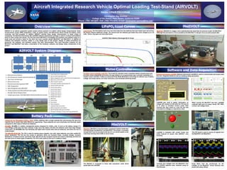
Load Curves: The first battery load curve test show data from the batteries that were tested upon arrival from
the factory without additional charge. The second time the batteries got tested they were charged up to 3.6
volts. Hence, they gave out more amp-hours.
LiFePO4 Load Curves MediVOLT
MediVOLT: MediVolt is a bigger, more sophisticated test stand than its previous model, the MiniVOLT.
Although this test stand is not as portable as the MiniVOLT it will give more accurate sample data.
Currents and voltages from the MediVOLT and
the LiFePO4 batteries were collected using an
Oscilloscope.
Using filters from the oscilloscope for the
voltages on the MediVOLT shows identical sine
waves with phase offsets.