SlideShare a Scribd company logo
1 of 4
Download to read offline
TECHNOLOGY FEATURE

Advancements in Laser Marking of Plastics
by Scott R. Sabreen, The Sabreen Group, Inc.


Advancements in direct laser marking of plastics yield
unprecedented marking quality, contrast, and speed. This
article presents the newest generation of laser material sci-
ence and laser equipment systems. With proper application,
laser marking can provide manufacturing advantages and
bring value to a product’s appearance and function.
                                                                                            Figure 2
Basic Principles of Laser Marking
Beam-steered Nd:YAG lasers (“YAG”) at 1064nm wave-              experts utilize additives and colorants (pigments & dyes)
length (near infrared spectrum) are popular in the laser        that enhance the absorption of laser energy yielding con-
marking industry due to their emission wavelength, power        trasting color changes. Contrary to popular belief, a single
performance and versatility. This results in faster marking     laser additive that solves all marking problems does not
speeds, higher quality, and greater production. As refer-       exist. Vastly different chemistries and laser parameters are
ence, the continuous wave (CW) CO2 lasers operate at a          used depending upon the desired marking contrast. Figure
wavelength of 10.6 µm (far infrared spectrum). CW CO2           2 shows “dark-on-light” computer keycap (left), “light-on-
lasers generate comparatively much lower peak power and         dark” interior automotive lever (center), and gold “color”
normally cannot produce high contrast markings on many          advertising specialty product (right).
plastics.
                                                                Three unique surface reactions are demonstrated in Figure 2.
The mechanism of laser marking is to irradiate the polymer      First, the charring process occurs when the energy absorbed
with a localized high-energy radiation source (laser). The      raises the local temperature of the material surrounding the
radiant energy is then absorbed by the material and converted   absorption site high enough to cause thermal degradation of
to thermal energy. The thermal energy induces reactions to      the polymer. While this can result in burning of the polymer
occur in the material. Beam-steered YAG laser markers (arc      in the presence of oxygen, the limited supply of oxygen in
lamp & diode light pumping sources) utilize mirrors that are    the interior of the substrate results in charring of the polymer
mounted on high speed computer controlled galvanometers         to form a black or dark-on-light marking contrast.
to direct the laser beam across the surface to be marked.
Each galvanometer, one on the Y-axis and one on the X-axis,     Second, the foaming process occurs when the local polymer
provides the beam motion within the marking field. A flat-      temperature surrounding the absorption site is sufficiently
field lens assembly focuses the laser light to achieve high     high that the polymer generates gases via burning or evapo-
power density on the substrate surface. A basic YAG laser       ration. The hot gases are themselves surrounded by molten
marking configura-                                              polymer and expand to form bubbles. If the energy of the
tion is shown below                                             laser is controlled, foaming can result in bubbles that scatter
in Figure 1.                                                    light in a way that results in white or light-on-dark marking
                                                                contrast1.
Laser Material
Science                                                         Third, laser energy is used to heat/degrade one colorant in
The material science                                            a colorant mixture resulting in a color change. An example
chemistry for achiev-                                           is a mixture of carbon black and a stable inorganic colorant.
ing high contrast laser                                         When heated, the carbon black is removed leaving behind
marking is both art                                             the inorganic colorant. These mixed colorant systems are
and science. Since                                              dependent on specific colorant stabilities and not all color
many polymers do                                                changes are possible. Laser formulations cannot be toxic or
not possess absorption                                          adversely affect the product’s appearance, physical proper-
properties at 1064 nm,                                          ties, or functional properties.
                                        Figure 1
34
A recent advancement is Mark-it™ Laser Marking Pigment             Power density is a function of focused laser spot size (laser
by BASF Corporation (formally Engelhard Corporation). This         power per unit area, watts/cm2). This is different than the raw
additive product is an antimony-doped tin oxide pigment that is    output power of the laser. Focused laser spot size for any given
easily dispersed in polymers. Mark-it™ pigment is the first to     focal length lens and laser wavelength is a function of laser
receive U.S. Food and Drug Administration (FDA) approval for       beam divergence which is controlled by laser configuration,
use in YAG laser marking processes to generate dark markings       mode selecting aperture size and upcollimator (beam expander)
(light markings also are achievable by incorporating additional    magnification. Pulse repetition rate (via acousto-optic Q-switch)
additives). The product has FDA approval for use at loadings up    and peak power density are critical parameters in forming
to 0.5 percent in polyolefins that contact food under conditions   the mark and achieving the optimal contrast and speed. High
A-H of 21 CFR 178.3297 Colorants for Polymers2.                    peak power at low frequency increases the surface temperature
                                                                   rapidly, vaporizing the material while conducting minimal heat
Laser Marking Equipment Systems                                    into the substrate. As the pulse repetition increases, a lower
All beam-steered YAG lasers are not created equal. The             peak power produces minimal vaporization but creates more
hardware and software components a laser manufacturer              heat. Beam velocity (speed of the laser beam across the work
incorporates into its systems makes significant differences        surface) is also a critical factor.
in marking quality, speed and versatility. When procuring
laser systems, it is important to remember there is not a single   Two types of solid-state beam-steered YAG lasers are tradi-
universal solution. Each application is unique relative to the     tionally used for marking plastics – lamp and diode-pumped
plastic substrate composition and color, marking quality,          systems (referred to as “lamp/YAG” and “diode/YAG”). Major
speed, laser efficiency, contrast (dark-on-light, light-on-dark,   differences exist between these two laser types. Both lamp/YAG
or color), and total system costs.                                 and diode/YAG can potentially yield acceptable marking results
                                                                   relative to marking contrast and speed. Table 1 provides com-
Beam quality output mode refers to the energy distribution         parative data (page 38) for lamp/YAG and diode/YAG lasers
within the laser beam and is critical to marking performance.      ranging from low to high power and configured for multimode
Lasers can be supplied by manufacturers as multimode (MM),         (MM) to TEM00 beam quality modes.
                                                                                                            continued on next page
TEM00 (Transverse Electromagnetic Mode) or anything in
between including Low-Order Mode (LOM). These output
modes relate to factors including the beam divergence and
power distribution across the diameter of the laser beam. A
TEM00 laser beam can be focused to the smallest size spot
that the focusing optics permit and the energy distribution in
a TEM00 laser beam is most intense at its center and tapers
off uniformly from its center to its edges. TEM00 laser output
provides the highest beam quality. Multi-Mode (MM) laser
output provides the poorest beam quality. Reference Figure 3.
Low-order and TEM00 mode lasers are particularly well suited
for high speed vector marking of single-stroke alphanumerics,
filled true-type fonts, and complex graphics because of their
ability to achieve a small focused spot with very high power
densities, resulting in a very narrow line with well defined
edges that can be drawn quickly. Most plastics applications
are optimal using near TEM00 or TEM00 laser beams.


                           Figure 3
                                                                                                                                 35
TECHNOLOGY FEATURE continued from page 35

For a direct comparison of diode/YAG versus lamp/YAG,           Lifetimes of laser-diode bank versus arc lamps are an im-
it is important to evaluate near equivalent lasers for a spe-   portant consideration. Most commonly advertised lifetime
cific application, e.g., 100-Watt. Using a 100-Watt laser as    of laser diodes operating in Q-switch mode are in the range
a basis, diode/YAG lasers are inherently more efficient than    of 10,000 hours, although the actual lifetime is dependent
lamp/YAG in terms of output beam power as a fraction of         upon a variety of factors and can vary significantly. When
input electrical power. Diode/YAG lasers rely on a bank         replacing a bank of diodes, the laser head is returned to
of laser diodes as the optical “pump” source for the YAG        the factory and the replacement cost can be in the range
laser rod, rather than a krypton arc lamp. Laser diodes are     of $12,000 to $15,000. In contrast, arc lamps have an op-
more sensitive than arc lamps to electrical noise so greater    erating range of 400-600 hours, based upon average usage
circuit protection is required. Contrary to common percep-      conditions, and can be easily replaced by a technician for
tion, both high-powered diode and lamp pumped lasers            about $100 or less. Advantage goes to diode/YAG lasers
require a cooling system, although diode systems can            relative to beam power stability since arc lamps age over
use smaller cooling units but require greater temperature       time. At present, lamp/YAG lasers are significantly less
control. Low power diode/YAG systems are sometimes              expensive to procure. Lamp/YAG is a much more mature
air-cooled. Diode/YAG lasers can produce TEM00 beam             technology and has been in use for decades (1960s). Di-
output quality, resulting in higher peak power and sub-         ode/YAG lasers (1980s) are the newer technology and they
sequent fast marking. Both lamp/YAG and diode/YAG               have longer mean time between maintenance intervals and
systems can produce TEM00 beam output quality, or near          lower electrical consumption and heating requirements.
TEM00 outputs, with proper apertures and collimation to         Lamp/YAG lasers often times can be more versatile when
produce similar spot sizes.                                     the marking of various substrates is required. The diode/
                                                                YAG is a more specialized laser machine.


                                                                                                       continued on page 38


36
TECHNOLOGY FEATURE continued from page 36
                                                                               Table 1
                     Comparison of Lamp Pump YAG versus Diode Pump YAG (Basis: 100-Watt laser, 220V, water-cooled)
Specification                                 Lamp Pump YAG                                                   Diode Pump YAG
Wavelength                                    1064 nm                                                         1064nm >
Raw Power                                     10 - 100 Watt MM                                                10-100 Watt MM
Power with Best Quality Output                1 - 22 Watt near TEM00                                          1 - 22 Watt TEM00
Beam quality mode                             MM to near TEM00                                                MM to TEM00
Beam power density                            Low to High                                                     Low to Very High
Spot Size                                     Focus lens, Upcollimator and Mode dependant                     Focus lens, Upcollimator and Mode dependant
Laser Pump Source Life                        400 - 600 hours                                                 8,000 - 10,000 hours
Pump Source Replacement Cost                  $50 - $100                                                      $12,000 - $15,000
Laser System Size                             Large                                                           Large to Small
Wall Plug Efficiency A                        1.5%                                                            5%
Operating cost annual B                       $3,200                                                          $4,100
Initial laser cost                            $48,000 – 60,000                                                $60,000 – $75,000

     A Laser (wall plug) efficiency is the electrical power drawn from the wall that must eventually be converted to laser output power. For example, if 1000
     watts of wall power consumption results in 15 watts of laser output, then the laser has a wall plug efficiency of 1.5 percent. It follows that 985 watts (98.5
     percent of the original 1000 watts) has been converted to heat, not laser output power, and must be removed somehow. Removal is generally accomplished
     by air or water cooling systems.
     B Reference Industrial Laser Solutions, August 2006, Glenn Prentice, Cost based on operating a typical laser eight hours per day, 254 days per year.


Laser control software is as important as any hardware                                References:
component in the marking system. Advanced software al-                                1. Bruce Mulholland (Ticona, formally Hoechst Technical Polymers) and
gorithms enable unprecedented speed. Beam-steered laser                               Scott Sabreen (The Sabreen Group, Inc.), “Enlightened Laser Marking”,
                                                                                      Lasers&Optronics, July 1997.
markers are sometimes wrongly conceptualized as (desktop)
printers. In fact, they are plotters. Rather than placing indi-                       2. BASF Corporation (formally Engelhard Corporation) Mark-it™ La-
vidual pixels to create alphanumeric letters or graphics, the                         ser Marking Pigment Technical Bulletin 2002, with technical content
laser draws lines much like writing with pencil and paper.                            contributions from The Sabreen Group, Inc.
Regardless of the input file format originally used to create
the laser marking objects, all marking is eventually reduced                          Scott R. Sabreen is founder and president of The Sabreen
to its most simple form, a list of vector lines to be drawn by                        Group Inc. (TSG). TSG is an engineering company special-
the scan head and marked by the laser. Complex input file                             izing in secondary plastics manufacturing – laser marking,
formats often used by design engineers may not necessarily                            surface pretreatments, bonding, decorating/finishing and
yield the best (or fastest) vector laser marking. Laser mark-                         product security. For more information, call toll-free at
ing equipment systems must be safe and conform to ANSI                                888-SABREEN or visit www.sabreen.com.
Z136 standards. n


38

More Related Content

What's hot

Construction Of Near Infrared Chiroptical Switches Based On Electrochromic Vi...
Construction Of Near Infrared Chiroptical Switches Based On Electrochromic Vi...Construction Of Near Infrared Chiroptical Switches Based On Electrochromic Vi...
Construction Of Near Infrared Chiroptical Switches Based On Electrochromic Vi...niba50
 
A Study on Uniform and Apodized Fiber Bragg Gratings
A Study on Uniform and Apodized Fiber Bragg GratingsA Study on Uniform and Apodized Fiber Bragg Gratings
A Study on Uniform and Apodized Fiber Bragg GratingsIJSRD
 
Sirris Materials Day 2010 K.U.Leuven - SLC - Compostie materials, trends and ...
Sirris Materials Day 2010 K.U.Leuven - SLC - Compostie materials, trends and ...Sirris Materials Day 2010 K.U.Leuven - SLC - Compostie materials, trends and ...
Sirris Materials Day 2010 K.U.Leuven - SLC - Compostie materials, trends and ...Sirris
 
Birefringence and Bragg grating control in femtosecond laser written optical ...
Birefringence and Bragg grating control in femtosecond laser written optical ...Birefringence and Bragg grating control in femtosecond laser written optical ...
Birefringence and Bragg grating control in femtosecond laser written optical ...Luís André Fernandes
 
Colorimetry (Physical Chemistry Concept)
Colorimetry (Physical Chemistry Concept)Colorimetry (Physical Chemistry Concept)
Colorimetry (Physical Chemistry Concept)PriyaGandhi35
 
Temperature and strain sensitivity of long period grating fiber sensor review
Temperature and strain sensitivity of long period grating fiber sensor    reviewTemperature and strain sensitivity of long period grating fiber sensor    review
Temperature and strain sensitivity of long period grating fiber sensor revieweSAT Journals
 
Optimization of Uniform Fiber Bragg Grating Reflection Spectra for Maximum Re...
Optimization of Uniform Fiber Bragg Grating Reflection Spectra for Maximum Re...Optimization of Uniform Fiber Bragg Grating Reflection Spectra for Maximum Re...
Optimization of Uniform Fiber Bragg Grating Reflection Spectra for Maximum Re...ijceronline
 
Poster: Nanomaterials Characteristics and Applicable Analytical Techniques
Poster: Nanomaterials Characteristics and Applicable Analytical TechniquesPoster: Nanomaterials Characteristics and Applicable Analytical Techniques
Poster: Nanomaterials Characteristics and Applicable Analytical TechniquesPerkinElmer, Inc.
 
Flash presentation inorganic nanoflam
Flash presentation   inorganic nanoflamFlash presentation   inorganic nanoflam
Flash presentation inorganic nanoflamMollyWinterbottom
 
2011 6 63158600
2011 6 631586002011 6 63158600
2011 6 63158600sarvari68
 
CeO2 Nanoparticles Report
CeO2 Nanoparticles ReportCeO2 Nanoparticles Report
CeO2 Nanoparticles ReportAyeman Mazdi
 
1. Synthesis of Polystyrene-Silica Composite Particles via One-Step Nanoparti...
1.	Synthesis of Polystyrene-Silica Composite Particles via One-Step Nanoparti...1.	Synthesis of Polystyrene-Silica Composite Particles via One-Step Nanoparti...
1. Synthesis of Polystyrene-Silica Composite Particles via One-Step Nanoparti...huanma
 
Raman spectroscopy in graphene
Raman spectroscopy in grapheneRaman spectroscopy in graphene
Raman spectroscopy in grapheneKiran Qamar Kayani
 

What's hot (20)

Construction Of Near Infrared Chiroptical Switches Based On Electrochromic Vi...
Construction Of Near Infrared Chiroptical Switches Based On Electrochromic Vi...Construction Of Near Infrared Chiroptical Switches Based On Electrochromic Vi...
Construction Of Near Infrared Chiroptical Switches Based On Electrochromic Vi...
 
A Study on Uniform and Apodized Fiber Bragg Gratings
A Study on Uniform and Apodized Fiber Bragg GratingsA Study on Uniform and Apodized Fiber Bragg Gratings
A Study on Uniform and Apodized Fiber Bragg Gratings
 
Sirris Materials Day 2010 K.U.Leuven - SLC - Compostie materials, trends and ...
Sirris Materials Day 2010 K.U.Leuven - SLC - Compostie materials, trends and ...Sirris Materials Day 2010 K.U.Leuven - SLC - Compostie materials, trends and ...
Sirris Materials Day 2010 K.U.Leuven - SLC - Compostie materials, trends and ...
 
Colorimetry
ColorimetryColorimetry
Colorimetry
 
Birefringence and Bragg grating control in femtosecond laser written optical ...
Birefringence and Bragg grating control in femtosecond laser written optical ...Birefringence and Bragg grating control in femtosecond laser written optical ...
Birefringence and Bragg grating control in femtosecond laser written optical ...
 
Colorimetry (Physical Chemistry Concept)
Colorimetry (Physical Chemistry Concept)Colorimetry (Physical Chemistry Concept)
Colorimetry (Physical Chemistry Concept)
 
Temperature and strain sensitivity of long period grating fiber sensor review
Temperature and strain sensitivity of long period grating fiber sensor    reviewTemperature and strain sensitivity of long period grating fiber sensor    review
Temperature and strain sensitivity of long period grating fiber sensor review
 
Optimization of Uniform Fiber Bragg Grating Reflection Spectra for Maximum Re...
Optimization of Uniform Fiber Bragg Grating Reflection Spectra for Maximum Re...Optimization of Uniform Fiber Bragg Grating Reflection Spectra for Maximum Re...
Optimization of Uniform Fiber Bragg Grating Reflection Spectra for Maximum Re...
 
Poster: Nanomaterials Characteristics and Applicable Analytical Techniques
Poster: Nanomaterials Characteristics and Applicable Analytical TechniquesPoster: Nanomaterials Characteristics and Applicable Analytical Techniques
Poster: Nanomaterials Characteristics and Applicable Analytical Techniques
 
final presentation
final presentationfinal presentation
final presentation
 
Flash presentation inorganic nanoflam
Flash presentation   inorganic nanoflamFlash presentation   inorganic nanoflam
Flash presentation inorganic nanoflam
 
Aem Lect14
Aem Lect14Aem Lect14
Aem Lect14
 
No2422242227
No2422242227No2422242227
No2422242227
 
2011 6 63158600
2011 6 631586002011 6 63158600
2011 6 63158600
 
CeO2 Nanoparticles Report
CeO2 Nanoparticles ReportCeO2 Nanoparticles Report
CeO2 Nanoparticles Report
 
Colorimetry
ColorimetryColorimetry
Colorimetry
 
PhD_Joris Salari
PhD_Joris SalariPhD_Joris Salari
PhD_Joris Salari
 
Radiochemical Properties of Irradiated PVA\AgNO3 Film by Electron Beam
Radiochemical Properties of Irradiated PVA\AgNO3 Film by Electron BeamRadiochemical Properties of Irradiated PVA\AgNO3 Film by Electron Beam
Radiochemical Properties of Irradiated PVA\AgNO3 Film by Electron Beam
 
1. Synthesis of Polystyrene-Silica Composite Particles via One-Step Nanoparti...
1.	Synthesis of Polystyrene-Silica Composite Particles via One-Step Nanoparti...1.	Synthesis of Polystyrene-Silica Composite Particles via One-Step Nanoparti...
1. Synthesis of Polystyrene-Silica Composite Particles via One-Step Nanoparti...
 
Raman spectroscopy in graphene
Raman spectroscopy in grapheneRaman spectroscopy in graphene
Raman spectroscopy in graphene
 

Similar to Advancements In Laser Marking Of Plastics By Scott R. Sabreen

Types of laser used in laser cutting machines
Types of laser used in laser cutting machinesTypes of laser used in laser cutting machines
Types of laser used in laser cutting machinesMarwan Shehata
 
Laser Processing of Different materials and its application.
Laser Processing of Different materials and its application.Laser Processing of Different materials and its application.
Laser Processing of Different materials and its application.aman1312
 
LASER BEAM MACHINING - NON TRADITIONAL MACHINING
LASER BEAM MACHINING - NON TRADITIONAL MACHININGLASER BEAM MACHINING - NON TRADITIONAL MACHINING
LASER BEAM MACHINING - NON TRADITIONAL MACHININGSajal Tiwari
 
Production technology
Production technologyProduction technology
Production technologySaumil Joshi
 
Laser ignition for Internal Combustion Engines Nitish Sharma
Laser ignition for Internal Combustion Engines  Nitish SharmaLaser ignition for Internal Combustion Engines  Nitish Sharma
Laser ignition for Internal Combustion Engines Nitish SharmaNitish Sharma
 
Presentation2 120316093400-phpapp01
Presentation2 120316093400-phpapp01Presentation2 120316093400-phpapp01
Presentation2 120316093400-phpapp01Paras Angrish
 
Laser beam machining
Laser beam machiningLaser beam machining
Laser beam machiningnurhulhaq
 
A Review on Laser marking by Nd-Yag Laser and Fiber Laser
 A Review on Laser marking by Nd-Yag Laser and Fiber Laser A Review on Laser marking by Nd-Yag Laser and Fiber Laser
A Review on Laser marking by Nd-Yag Laser and Fiber Laserijsrd.com
 
Laser ignition report
Laser ignition reportLaser ignition report
Laser ignition reportvikas_17
 
fdocuments.in_laser-beam-welding-55b0f8668bb2f.pdf
fdocuments.in_laser-beam-welding-55b0f8668bb2f.pdffdocuments.in_laser-beam-welding-55b0f8668bb2f.pdf
fdocuments.in_laser-beam-welding-55b0f8668bb2f.pdfbalamurugan63307
 
Laser beam welding
Laser beam weldingLaser beam welding
Laser beam weldingAntwin Koshy
 

Similar to Advancements In Laser Marking Of Plastics By Scott R. Sabreen (20)

Types of laser used in laser cutting machines
Types of laser used in laser cutting machinesTypes of laser used in laser cutting machines
Types of laser used in laser cutting machines
 
lbm-170421104831.ppt x
lbm-170421104831.ppt                         xlbm-170421104831.ppt                         x
lbm-170421104831.ppt x
 
Laser Beam machining Process
Laser Beam machining ProcessLaser Beam machining Process
Laser Beam machining Process
 
Laser Processing of Different materials and its application.
Laser Processing of Different materials and its application.Laser Processing of Different materials and its application.
Laser Processing of Different materials and its application.
 
Hebatalrahman zeolite
Hebatalrahman zeoliteHebatalrahman zeolite
Hebatalrahman zeolite
 
Composite from zeolite
Composite from zeoliteComposite from zeolite
Composite from zeolite
 
LASER BEAM MACHINING - NON TRADITIONAL MACHINING
LASER BEAM MACHINING - NON TRADITIONAL MACHININGLASER BEAM MACHINING - NON TRADITIONAL MACHINING
LASER BEAM MACHINING - NON TRADITIONAL MACHINING
 
Hebatalrahman nanotreatment
Hebatalrahman nanotreatmentHebatalrahman nanotreatment
Hebatalrahman nanotreatment
 
Hebatalrahman nanotreatment
Hebatalrahman nanotreatmentHebatalrahman nanotreatment
Hebatalrahman nanotreatment
 
Hebatalrahman nanotreatment
Hebatalrahman nanotreatmentHebatalrahman nanotreatment
Hebatalrahman nanotreatment
 
Production technology
Production technologyProduction technology
Production technology
 
Laser systems
Laser systemsLaser systems
Laser systems
 
Laser ignition for Internal Combustion Engines Nitish Sharma
Laser ignition for Internal Combustion Engines  Nitish SharmaLaser ignition for Internal Combustion Engines  Nitish Sharma
Laser ignition for Internal Combustion Engines Nitish Sharma
 
Presentation2 120316093400-phpapp01
Presentation2 120316093400-phpapp01Presentation2 120316093400-phpapp01
Presentation2 120316093400-phpapp01
 
CO2 and N2 Lasers
CO2 and N2 LasersCO2 and N2 Lasers
CO2 and N2 Lasers
 
Laser beam machining
Laser beam machiningLaser beam machining
Laser beam machining
 
A Review on Laser marking by Nd-Yag Laser and Fiber Laser
 A Review on Laser marking by Nd-Yag Laser and Fiber Laser A Review on Laser marking by Nd-Yag Laser and Fiber Laser
A Review on Laser marking by Nd-Yag Laser and Fiber Laser
 
Laser ignition report
Laser ignition reportLaser ignition report
Laser ignition report
 
fdocuments.in_laser-beam-welding-55b0f8668bb2f.pdf
fdocuments.in_laser-beam-welding-55b0f8668bb2f.pdffdocuments.in_laser-beam-welding-55b0f8668bb2f.pdf
fdocuments.in_laser-beam-welding-55b0f8668bb2f.pdf
 
Laser beam welding
Laser beam weldingLaser beam welding
Laser beam welding
 

More from SabreenGroup

Inkjet Printing On Plastics By Scott Sabreen
Inkjet Printing On Plastics By Scott SabreenInkjet Printing On Plastics By Scott Sabreen
Inkjet Printing On Plastics By Scott SabreenSabreenGroup
 
Inkjet Printing On Plastics By Scott Sabreen
Inkjet Printing On Plastics By Scott SabreenInkjet Printing On Plastics By Scott Sabreen
Inkjet Printing On Plastics By Scott SabreenSabreenGroup
 
Technology Developments For Inkjet Printing By Scott Sabreen
Technology Developments For  Inkjet Printing By Scott SabreenTechnology Developments For  Inkjet Printing By Scott Sabreen
Technology Developments For Inkjet Printing By Scott SabreenSabreenGroup
 
Techniques For Measuring Adhesion Abrasion Durability Of Coatings Inks By Sco...
Techniques For Measuring Adhesion Abrasion Durability Of Coatings Inks By Sco...Techniques For Measuring Adhesion Abrasion Durability Of Coatings Inks By Sco...
Techniques For Measuring Adhesion Abrasion Durability Of Coatings Inks By Sco...SabreenGroup
 
Adhesive Bond Failure Modes
Adhesive Bond Failure ModesAdhesive Bond Failure Modes
Adhesive Bond Failure ModesSabreenGroup
 
Coloring Plastics For Special Decorative Effects
Coloring Plastics For Special Decorative EffectsColoring Plastics For Special Decorative Effects
Coloring Plastics For Special Decorative EffectsSabreenGroup
 
Solving The Problems Of Plastics Adhesion By Scott Sabreen
Solving The Problems Of Plastics Adhesion By Scott SabreenSolving The Problems Of Plastics Adhesion By Scott Sabreen
Solving The Problems Of Plastics Adhesion By Scott SabreenSabreenGroup
 

More from SabreenGroup (7)

Inkjet Printing On Plastics By Scott Sabreen
Inkjet Printing On Plastics By Scott SabreenInkjet Printing On Plastics By Scott Sabreen
Inkjet Printing On Plastics By Scott Sabreen
 
Inkjet Printing On Plastics By Scott Sabreen
Inkjet Printing On Plastics By Scott SabreenInkjet Printing On Plastics By Scott Sabreen
Inkjet Printing On Plastics By Scott Sabreen
 
Technology Developments For Inkjet Printing By Scott Sabreen
Technology Developments For  Inkjet Printing By Scott SabreenTechnology Developments For  Inkjet Printing By Scott Sabreen
Technology Developments For Inkjet Printing By Scott Sabreen
 
Techniques For Measuring Adhesion Abrasion Durability Of Coatings Inks By Sco...
Techniques For Measuring Adhesion Abrasion Durability Of Coatings Inks By Sco...Techniques For Measuring Adhesion Abrasion Durability Of Coatings Inks By Sco...
Techniques For Measuring Adhesion Abrasion Durability Of Coatings Inks By Sco...
 
Adhesive Bond Failure Modes
Adhesive Bond Failure ModesAdhesive Bond Failure Modes
Adhesive Bond Failure Modes
 
Coloring Plastics For Special Decorative Effects
Coloring Plastics For Special Decorative EffectsColoring Plastics For Special Decorative Effects
Coloring Plastics For Special Decorative Effects
 
Solving The Problems Of Plastics Adhesion By Scott Sabreen
Solving The Problems Of Plastics Adhesion By Scott SabreenSolving The Problems Of Plastics Adhesion By Scott Sabreen
Solving The Problems Of Plastics Adhesion By Scott Sabreen
 

Advancements In Laser Marking Of Plastics By Scott R. Sabreen

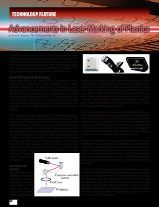
  • 1. TECHNOLOGY FEATURE Advancements in Laser Marking of Plastics by Scott R. Sabreen, The Sabreen Group, Inc. Advancements in direct laser marking of plastics yield unprecedented marking quality, contrast, and speed. This article presents the newest generation of laser material sci- ence and laser equipment systems. With proper application, laser marking can provide manufacturing advantages and bring value to a product’s appearance and function. Figure 2 Basic Principles of Laser Marking Beam-steered Nd:YAG lasers (“YAG”) at 1064nm wave- experts utilize additives and colorants (pigments & dyes) length (near infrared spectrum) are popular in the laser that enhance the absorption of laser energy yielding con- marking industry due to their emission wavelength, power trasting color changes. Contrary to popular belief, a single performance and versatility. This results in faster marking laser additive that solves all marking problems does not speeds, higher quality, and greater production. As refer- exist. Vastly different chemistries and laser parameters are ence, the continuous wave (CW) CO2 lasers operate at a used depending upon the desired marking contrast. Figure wavelength of 10.6 µm (far infrared spectrum). CW CO2 2 shows “dark-on-light” computer keycap (left), “light-on- lasers generate comparatively much lower peak power and dark” interior automotive lever (center), and gold “color” normally cannot produce high contrast markings on many advertising specialty product (right). plastics. Three unique surface reactions are demonstrated in Figure 2. The mechanism of laser marking is to irradiate the polymer First, the charring process occurs when the energy absorbed with a localized high-energy radiation source (laser). The raises the local temperature of the material surrounding the radiant energy is then absorbed by the material and converted absorption site high enough to cause thermal degradation of to thermal energy. The thermal energy induces reactions to the polymer. While this can result in burning of the polymer occur in the material. Beam-steered YAG laser markers (arc in the presence of oxygen, the limited supply of oxygen in lamp & diode light pumping sources) utilize mirrors that are the interior of the substrate results in charring of the polymer mounted on high speed computer controlled galvanometers to form a black or dark-on-light marking contrast. to direct the laser beam across the surface to be marked. Each galvanometer, one on the Y-axis and one on the X-axis, Second, the foaming process occurs when the local polymer provides the beam motion within the marking field. A flat- temperature surrounding the absorption site is sufficiently field lens assembly focuses the laser light to achieve high high that the polymer generates gases via burning or evapo- power density on the substrate surface. A basic YAG laser ration. The hot gases are themselves surrounded by molten marking configura- polymer and expand to form bubbles. If the energy of the tion is shown below laser is controlled, foaming can result in bubbles that scatter in Figure 1. light in a way that results in white or light-on-dark marking contrast1. Laser Material Science Third, laser energy is used to heat/degrade one colorant in The material science a colorant mixture resulting in a color change. An example chemistry for achiev- is a mixture of carbon black and a stable inorganic colorant. ing high contrast laser When heated, the carbon black is removed leaving behind marking is both art the inorganic colorant. These mixed colorant systems are and science. Since dependent on specific colorant stabilities and not all color many polymers do changes are possible. Laser formulations cannot be toxic or not possess absorption adversely affect the product’s appearance, physical proper- properties at 1064 nm, ties, or functional properties. Figure 1 34
  • 2. A recent advancement is Mark-it™ Laser Marking Pigment Power density is a function of focused laser spot size (laser by BASF Corporation (formally Engelhard Corporation). This power per unit area, watts/cm2). This is different than the raw additive product is an antimony-doped tin oxide pigment that is output power of the laser. Focused laser spot size for any given easily dispersed in polymers. Mark-it™ pigment is the first to focal length lens and laser wavelength is a function of laser receive U.S. Food and Drug Administration (FDA) approval for beam divergence which is controlled by laser configuration, use in YAG laser marking processes to generate dark markings mode selecting aperture size and upcollimator (beam expander) (light markings also are achievable by incorporating additional magnification. Pulse repetition rate (via acousto-optic Q-switch) additives). The product has FDA approval for use at loadings up and peak power density are critical parameters in forming to 0.5 percent in polyolefins that contact food under conditions the mark and achieving the optimal contrast and speed. High A-H of 21 CFR 178.3297 Colorants for Polymers2. peak power at low frequency increases the surface temperature rapidly, vaporizing the material while conducting minimal heat Laser Marking Equipment Systems into the substrate. As the pulse repetition increases, a lower All beam-steered YAG lasers are not created equal. The peak power produces minimal vaporization but creates more hardware and software components a laser manufacturer heat. Beam velocity (speed of the laser beam across the work incorporates into its systems makes significant differences surface) is also a critical factor. in marking quality, speed and versatility. When procuring laser systems, it is important to remember there is not a single Two types of solid-state beam-steered YAG lasers are tradi- universal solution. Each application is unique relative to the tionally used for marking plastics – lamp and diode-pumped plastic substrate composition and color, marking quality, systems (referred to as “lamp/YAG” and “diode/YAG”). Major speed, laser efficiency, contrast (dark-on-light, light-on-dark, differences exist between these two laser types. Both lamp/YAG or color), and total system costs. and diode/YAG can potentially yield acceptable marking results relative to marking contrast and speed. Table 1 provides com- Beam quality output mode refers to the energy distribution parative data (page 38) for lamp/YAG and diode/YAG lasers within the laser beam and is critical to marking performance. ranging from low to high power and configured for multimode Lasers can be supplied by manufacturers as multimode (MM), (MM) to TEM00 beam quality modes. continued on next page TEM00 (Transverse Electromagnetic Mode) or anything in between including Low-Order Mode (LOM). These output modes relate to factors including the beam divergence and power distribution across the diameter of the laser beam. A TEM00 laser beam can be focused to the smallest size spot that the focusing optics permit and the energy distribution in a TEM00 laser beam is most intense at its center and tapers off uniformly from its center to its edges. TEM00 laser output provides the highest beam quality. Multi-Mode (MM) laser output provides the poorest beam quality. Reference Figure 3. Low-order and TEM00 mode lasers are particularly well suited for high speed vector marking of single-stroke alphanumerics, filled true-type fonts, and complex graphics because of their ability to achieve a small focused spot with very high power densities, resulting in a very narrow line with well defined edges that can be drawn quickly. Most plastics applications are optimal using near TEM00 or TEM00 laser beams. Figure 3 35
  • 3. TECHNOLOGY FEATURE continued from page 35 For a direct comparison of diode/YAG versus lamp/YAG, Lifetimes of laser-diode bank versus arc lamps are an im- it is important to evaluate near equivalent lasers for a spe- portant consideration. Most commonly advertised lifetime cific application, e.g., 100-Watt. Using a 100-Watt laser as of laser diodes operating in Q-switch mode are in the range a basis, diode/YAG lasers are inherently more efficient than of 10,000 hours, although the actual lifetime is dependent lamp/YAG in terms of output beam power as a fraction of upon a variety of factors and can vary significantly. When input electrical power. Diode/YAG lasers rely on a bank replacing a bank of diodes, the laser head is returned to of laser diodes as the optical “pump” source for the YAG the factory and the replacement cost can be in the range laser rod, rather than a krypton arc lamp. Laser diodes are of $12,000 to $15,000. In contrast, arc lamps have an op- more sensitive than arc lamps to electrical noise so greater erating range of 400-600 hours, based upon average usage circuit protection is required. Contrary to common percep- conditions, and can be easily replaced by a technician for tion, both high-powered diode and lamp pumped lasers about $100 or less. Advantage goes to diode/YAG lasers require a cooling system, although diode systems can relative to beam power stability since arc lamps age over use smaller cooling units but require greater temperature time. At present, lamp/YAG lasers are significantly less control. Low power diode/YAG systems are sometimes expensive to procure. Lamp/YAG is a much more mature air-cooled. Diode/YAG lasers can produce TEM00 beam technology and has been in use for decades (1960s). Di- output quality, resulting in higher peak power and sub- ode/YAG lasers (1980s) are the newer technology and they sequent fast marking. Both lamp/YAG and diode/YAG have longer mean time between maintenance intervals and systems can produce TEM00 beam output quality, or near lower electrical consumption and heating requirements. TEM00 outputs, with proper apertures and collimation to Lamp/YAG lasers often times can be more versatile when produce similar spot sizes. the marking of various substrates is required. The diode/ YAG is a more specialized laser machine. continued on page 38 36
  • 4. TECHNOLOGY FEATURE continued from page 36 Table 1 Comparison of Lamp Pump YAG versus Diode Pump YAG (Basis: 100-Watt laser, 220V, water-cooled) Specification Lamp Pump YAG Diode Pump YAG Wavelength 1064 nm 1064nm > Raw Power 10 - 100 Watt MM 10-100 Watt MM Power with Best Quality Output 1 - 22 Watt near TEM00 1 - 22 Watt TEM00 Beam quality mode MM to near TEM00 MM to TEM00 Beam power density Low to High Low to Very High Spot Size Focus lens, Upcollimator and Mode dependant Focus lens, Upcollimator and Mode dependant Laser Pump Source Life 400 - 600 hours 8,000 - 10,000 hours Pump Source Replacement Cost $50 - $100 $12,000 - $15,000 Laser System Size Large Large to Small Wall Plug Efficiency A 1.5% 5% Operating cost annual B $3,200 $4,100 Initial laser cost $48,000 – 60,000 $60,000 – $75,000 A Laser (wall plug) efficiency is the electrical power drawn from the wall that must eventually be converted to laser output power. For example, if 1000 watts of wall power consumption results in 15 watts of laser output, then the laser has a wall plug efficiency of 1.5 percent. It follows that 985 watts (98.5 percent of the original 1000 watts) has been converted to heat, not laser output power, and must be removed somehow. Removal is generally accomplished by air or water cooling systems. B Reference Industrial Laser Solutions, August 2006, Glenn Prentice, Cost based on operating a typical laser eight hours per day, 254 days per year. Laser control software is as important as any hardware References: component in the marking system. Advanced software al- 1. Bruce Mulholland (Ticona, formally Hoechst Technical Polymers) and gorithms enable unprecedented speed. Beam-steered laser Scott Sabreen (The Sabreen Group, Inc.), “Enlightened Laser Marking”, Lasers&Optronics, July 1997. markers are sometimes wrongly conceptualized as (desktop) printers. In fact, they are plotters. Rather than placing indi- 2. BASF Corporation (formally Engelhard Corporation) Mark-it™ La- vidual pixels to create alphanumeric letters or graphics, the ser Marking Pigment Technical Bulletin 2002, with technical content laser draws lines much like writing with pencil and paper. contributions from The Sabreen Group, Inc. Regardless of the input file format originally used to create the laser marking objects, all marking is eventually reduced Scott R. Sabreen is founder and president of The Sabreen to its most simple form, a list of vector lines to be drawn by Group Inc. (TSG). TSG is an engineering company special- the scan head and marked by the laser. Complex input file izing in secondary plastics manufacturing – laser marking, formats often used by design engineers may not necessarily surface pretreatments, bonding, decorating/finishing and yield the best (or fastest) vector laser marking. Laser mark- product security. For more information, call toll-free at ing equipment systems must be safe and conform to ANSI 888-SABREEN or visit www.sabreen.com. Z136 standards. n 38