
More Related Content
Similar to Adobe Scan Apr 27, 2023 (2).pdf
Similar to Adobe Scan Apr 27, 2023 (2).pdf (20)
Recently uploaded
Recently uploaded (20)
Adobe Scan Apr 27, 2023 (2).pdf
- 2. DC Över Voltage RelayConnection Diagram in 175AH Float Charger MCC-1 P 230 V ACP ControlON/OFF Selector Switch AC DPMCB 2A SS 52 N 51 N 230 V AC MCCB 80A A1 A2 DC O/V RELAY RM22UA23MR E1 E2 E3 12 22 CFL TUBE BUZZER +Ve 11 21 B 24 V -Ve M -Ve 14 24 OF10 OF11 DC MCB OF12 NC Contact forTripping E2-Voltage Range 30-300 Vac/dc M is -Ve and E2 is +ve. ALARM O DISPLAY A1 220 VDC +/ AC To Outgoing Load CONTACTOR MNX-90 AcC-1 DC MCB-9 A2
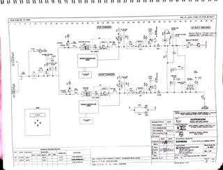
- 4. 1 Work Order No. CE-2895 REV 8 3 27.10.12 DATEPREPARED 4 PMP 16.04.13|NPB. 5 6 7 8 DRAWING RELEASE RECORD REVIEWED MECHCIVILELECT. C&1. SES SSP DJ.P. 11 D.J.P 2 3 4 5 7 9 10 11 12 13 14 15 16 17 18 19 20 APPROVED 21 12 13 SWITCH 14 SHUNT CONTACTOR NO CONTACT DIODE CONTACTOR NC CONTACT AMMETER VOLTMETER AUX. RELAY/ CONT,COIL FUSE THERMOSTAT 15 AUX RELAT NO CONTACT CHOKE AUX RELAT NC CONTACT FILTER CONDENSOR RESISTANCE HEATER MCB 16 FUSE FAIL DETECTOR MCCB TRANSFORMER LAMPS 17 REVISION FOR APPROVAL AS BUILT DRAWING 18 19 20 mm 21 22 23 Rating :FC-FCBC 220V/65A-85A 22 23 24 Type :FC-FCBC CP - CC: 220U /65A-85A 25 26 SCR Unit :220V/175AH PLANTE L.A.BATT. CHARGER WITH DCDB. SWITCH FUSE UNIT 27 28 29 31 RELEASE STATUS PRELIMINARY FOR INFORMATION FOR APPROVAL 16.04.13 FOR CONSTRUCTIN VAS BUILT ELECT C&I. SES. SIGN 33 DATE Approved :D.J.P. DATE IssPST6.o4.13 Flle :01 220V-175AH_FC+FCB_AS BUILT 34 PROJECT: aUENT 35 JavPEE JAYPEE NIGRIE SUPER THERMAL 36 37 38 39 (AS BUILT DRAIWNG |Battery Rating -175 AH (YKP-15) ion SS1 ( CHP Main MCC) COAL HANDUNG PLNTCHP k650M cONTRAÇTOR: CHENTSs cONSULTANT: DRAWN BY N.P.B16.04.13 SIEMENS MECH. MANUFACTURER: ocIVIL. Chhahl Flegtrisala Priate Limand Regd Ottloe &Factory: JAIPRAKASH DEVELOPMENT CONSULTANTS PVT. LTD 24 PARK STREET.KOLKATA INDIA POWER VENTURES LIMITED LARSEN &TOUBRO UMITED MMHIC-BMH LaT ELECTRICAL CONTRACTOR SCALE: 1:1E. sIZE : A3 VENDOR DWG No.:C15091 I IS MT MI PS (S) CHENNAI OFFICE Ms 0528/n28 LEGEND FOR SYMBOL Work Order No. : CE-2895 Qty. :1 No. SHT:S3 OF s27 Rey. 01
- 5. 1 Work Order No. CE-2895 REV 01 T2 T4 3 1X3 1/2C X120SQ. MM AL CABLE T×A 5 8 3 DATEPREPARED 5 1 X3 1/2C X 120sQ. MM AL CABLE 27.10.12 PMP 6 16.04.13 N.P.B. 7 A1 BA 8 S.s.P. (9) ACSW1 |sSP. (9) ACSW1 125A ACSW1 MECH CIVIL ELECT. C&I. SES. 10 201 21 22 23) 24 25) DRAWING RELEASE RECORD REVIEWED ACL S8.39 23 24 T25 T26 T28 D.JP 11 APPROVED D.J.P. 9 10 11 12 ACN S8.39 12 13 RFI-1 14 REVISION 17 18 44 FOR APPROVAL AS BUILT DRAWING 15 16 DOS1 ACCA1 ACMCB1 ACMCB2 17 0-500v A) 27 ACVM1 13 18 19 ACTR2 ACSW2 CF2 CFL1 NTH 14ol15 20 21 31] S12.6 ACCA2 VT 22 (33) a/10 34 23 35, ACCT1 24 ACSW3 ACCT2 Type :FC-FCBC CP - CC: 220V /65A-85A 25 ACCT3 39S2.3 26 0-100A Si.3 Unit :220V/175AH PLANTE L.A.BATT,CHARGER WITH DCDB. Rating :FC-FCBC 220V/65A-85A 27 28 29 MECH. CHECKED BY o CIVIL. 30 CaI. 31 SES. SR1 S7.2 32 SY1S7.2 sB1 S7.2 SN1 S7.2 5. ACCT1 -4: CUR 1. ACSW1 : SOURCE CHANGE OVER SWITCH 4. ACAMi: Ac ATMETER RELEASE STATUS PRELIMINARY FOR INFORMATION FOR APPROVAL FOR CONSTRUCTICN VAS BUILT 2. ACCA1 &2 : AC MAINS FAIL INDICATION CONTACTOR 6. ACSw2 &3: SEL ECTO Approved :D.J.P. 33 8. TH1 : THERMOSTATE 9. H1: SPACE HEATER SR2S5.2 SY2 S5.2 WITH 2 NO + 2 NC AUX CONT. SB2 S5.2 SN2 S5.2 SIGN 7. ACMCB1 & 2: 34 MMETER 10. SOCKET: UTILTIY POWER SUPPLY DATE File :01 220V-175AH_ FC+FCB_AS BUILT 12 ACTR1 : AUILIARY TRANSFORMER 11. AC LED1-3 : AC SOURCE ON INDICATION 16.04.13 ELECT.s.s.P.yi6.o4.13 DATE TRANSFORMER 3 PROJECT (AS BUILT DRAIWNG Battery Rating -175 AH (YKP-15)1 Locatión SS1 CHP Main MCC) UENT: DRAWN BY N.P.A 6.04.13 SIEMENS JAYPEE 36 37 cONTRACTOR: JAYPEE NIGRIE SUPERTHERMALPOER CIENT'S CONSULTANT: MANUFACTURER: SPACE HEATER A3 L&T ELECTRICAL CONTRACTOR: SCALE: 1:1/TITLE: SIZE 38 39 40 ING PLANT CHP,PAK660M DEVELOPMENT CONSULTANTS PVT. LTD 24 PARK STREET,KOLKATA INDIA Fa No 91-257-221434 JAIPRAKASH POWER VENTURES LIMTED LARSEN &TOUBRO UMITED MMH IC-BMH AChbebi Electrisals Private LAmked Regd. OMce &Factory E6, MOno082128 VENDOR oWG NO.:C1 5091A IIS MT MI PS (S) CHENNAI OFFICE Work Order No. CE-2895 met Qty. :1 No. MAIN CKT. DIA. FOR 220V BATTERY CHARGER SHT:S4 Rev OF S27 FOR SUPDOR ACVM1&ACAM1
- 6. 1 Work Order No. CE-2895 S89 S4.30 SN2 REV 00 3 41 42 43 44 6 DATE PREPARED 27.10.12 PMP 63A 50KA 01 1604.13 NPB ACMCCB1 7 8 45 46 47 1. ACMCCB1: AC INPUT SUPPLY ON/OFF MCCB ACC1 MAIN CONTACTOR 10 ACFS4 4. MTR1 : MAIN TRANSFORMER FOR FLOAT CHARGER REVIEWED MECHcrVIL ELECT S.S.P. DRAWING RELEASE RECORD 11 C&I. SES ACFS5 INPUT SUPPLY INDICATING LAMP D.J.P 12 APPROVED D.J.P. 13 ACFS7 ACSW4 14 TA1 A2 ACC1 REVISION 15 FOR APPROVAL AS BUILT DRAWING 16 17 180 19 20 24 50A 415VAC (13) ACC1 22 23 24 53 54) Type :FC-FCBC CP -CC: 220V/65A-85A 25 55 26 27 Unit :220V/175AH PLANTE L.A.BATT. CHARGER WITH DCDB. Rating :FC-FCBC 220V/65A-85A 29 38 C&I. 456V/265V 24.5 KVA MTR1 RELEASE STATUS PRELIMINARY FOR INFORMATION FOR APPROVAL 16.04.13 FOR CONSTRUCTION VAS BUILT SES. 33 DATE SIGN DRAWN BYN.P.BA.6.04.13 |MECH. CIVIL. Approved :D.J.P. DATE ELECT. S.s.P6.04.13 56 R1 57Y1 File :01_220V-175AH_FC+FCB_AS BUILT 34 58 PROJECT: JATPEE aIENT 35 S6.1 S6.2 S6.2 JAYPEE NIGRIE 36 CONTRATOR: Battery Rating -175 AH ( YKP-15)] Locatión SS1(CHP Main MCC) CIENTs CONSULTANT: 37 (AS BUILT DRAIWNG FLOAT CHARGER SIZE: A3 38 39 LAT ELECTRICAL CONTRACTOR: SCALE: 1:1TITLE: THERMAL POWE DRO1ECT JAIPRAKASH POWER VENTURES IMITED DEVELOPMENT CONSULTANTS PVT. LTD 24PARK STREET,KOLKAT INDIA 40 Chhakl ElectrÍçals Privnte lánitcd Pnone No91757-2M066/728 Ehsaechametn LARSEN &TOUBRO LIMITED MMH 1C-BMH SIEMENS IIS MT MI PS (S) CHENNAI OFFICE MANUFACTURER: VENDOR DWG NO.:C15091B Work Order No. CE-2895 Qty. :1 No. HCKT. DAI. FOR 220V FLOAT CHARGER SHT:SS OF S27 Rev. 01
- 8. 1 Work Order No. CE-2895 S5.29 XB1 2 SS.27 XR1 S5.28 XY1 S8A.2 LS1 S8A.2 LS2 REV 01 55 53 54 168 185) 415V AC SUPPLY 00 27.10.12 PMp 415V AC SUPPLY DATE PREPARED 16.04.13 N.PB. I/P 6 O/P ZCD1 O/P PSTRI 7 ZCDRI +5V VCc ZCDY1 ZCDB1 0-21vAC GNC 0-18V AC (300mA) o/P (1A) 0-12V AC (300mA) O-12V AC (300mA) 0-12V AC (300mA) 0-24V AC (300mA) DC TO DC3 0-24V DC 500mA 0-24V DCc 300mA 0-12V DC 300mA 0-30v Dc 300mA 288 S.S.P. S.S.P. 289 290 291 292 293) 294 295 9 10 283) 280 284] 285] 286] 287 279) 281 282 2711 272 276 277 273 278 274) 275 14 DRAWING RELEASSE RECORD REVIEWED MECH CIVIL ELECT. C&I. SES |296| 297 HMI-1 D.J.P. KEY PAD APPROVED D.J.P. 16 X 2LCD WITH 12 ZCD P/S AC POWER SUPPLY DC POWER SUPPLY 13 SFB 14 K1 CHR REVISION G1 K2 15 FOR APPROVAL AS BUILT DRAWING 16 17 G2 K3 G3 K4 DIGITAL ðP FRM 18 CH A/N 19 SCR FIRING PULSE BST Ge 20 K5 21 A/M EXT 424 22 G5 K6 GE CMU-10T-FC UN 23 ON 24 DIGITAL O/P Type :FC-FCBC CP - CC: 220V /65A-85A 25 MODBUS 26 CANBUS 27 CH.VOLT+ CH.AMP BRIDGE AMP BATT.VOLT Unit :220V/175AH PLANTE L.A.BATT. CHARGER WITH DCDB. Rating:FC-FCBC 22OV/65A-85A BATT.CURRENT BATT.TEMP (420mA) +24 1 28 92 90 91 29 30 S6.34 C&I. MV1 SES. S6.30 34 RELEASE STATUS DATE PRELIMINARY FOR INFORMATION FOR APPROVAL FOR CONSTRUCTICN VAS BUILT SIGN DRAWN BYN.P.B. MECH. oCIVIL 32 Approved :D.J.P. 33 ELECT. S.S.P.6.04.13 16.04.13 |PROJECT: DATE x6.04.13 Fille :01_220V-175AH FC+FCB AS BUILT 34 CUENT : JAYPEE 35 36 37 38 JAYPEE NIGRIESUPERTHERMAL POWER AS BUILT DRAIWNG) FLOAT CHARGER Battery Rating - 175AH (YKP-15)1 Location S$17CHP Main MCC) CLIENTS CONSULTANT: CONTRAGTOR: COAL HANDLING PUANT CHBSS 2X660MW MANUFACTURER JAIPRAKASH LAT ELECTRICAL CONTRACTOR: SIZE A3 39 SCALE: 1:1 TITLE: POWER VENTUREs LIMITED DEVELOPMENT CONSULTANTS PVT. LTD 24PARK STREET KOLKATAINDIA SIEMENS 11S MT MI PS (S) CHENNAI OFFICE Chbabi Electrigals Private Limtog. 40 LARSEN &TOUBRO LIMITED MMH IC-BMH :ohata alsanchamet D82s/2723 VENDOR DWG NO.:C15091C1 Work Order No. : CE-2895 Qty. :1 No. HCKT, DIA, FOR FC RECTFIER MODULE SHT:S6A Rev. OF S27 01
- 9. REV 00 1 01 Work Order No. CE-2895 2 3 41 42 43 44 4 5 DATE PREPARED 6 27.10.12 PMP 16.04 13 NPB 63A 50KA 3. ACC2: MAIN CONTACTOR 7 ACMCCB2 ACMCCB2 : AC INPUT SUPPLY ON/OFF MCCB 2. ACLED 7-9:FCB CH ACINPUTSUPPLY INDICATING LAMP 94 95) 4. MTR2 : MAIN TRANSFORMER FOR FCB CHARGER 96 SSP DRAWING RELEASE RECORD REVIEWED MECHCIVIL ELECT C&1. SES 10 APPROVED D.JP. DJP 12 13 REVISION FOR APPROVAL 14 AS BUILT DRAWING (szNBS) 15 16 100) zors) sB/35| 17 ACFS11 ACSWS ACC2 18 20 21 22 23 Type :FC-FCBC Cp -CC: 220V /65A-85A 24 50A 415VAC (17) ACC2 3a4 5 6 25 Unit :220V/175AH PLANTE LIA.BATT. CHARGER WITH DCDB. Rating :FC-FCBC 220V/65A-85A 26 103 27 104) 105 28 29 30 RELEASE STATUS PRELIMINARY C&I. SES. 31 FOR INFORMATION FOR APPROVAL FOR CONSTRUCTION VAS BUILT Approved :D.J.P. 32 DATE SIGN DRAWN BY N.P.B. MECH. oCIVIL. ELECT. S.s.P.6.04.13 (lo0-|o3) 16.04.13 33 DATE PRO File :01 220V-175AH FC+FCB AS BUILT 34 Ana. (ot ty 3TH3e 22¬ o2k 456V/295V 35.5 KVA MTR2 aUENT FLOAT CUM BOOST CHARGER 35 CONTRASIOR CAS BUILT DRAIWNG CIENTs CONSULTANT: 0413 SIEMENS MANUFACTURER SIZE A3 36 37 JAYPEE NIGRIE SUPER THERMAL POWER PROJECT Battery Rating - 175AH(YKP-15)] LOcation SS1 CHP MainMCC) SCALE: 1:1/TITLE: 38 106) 107 108 B2 COAL HANDLING PTANT CHPSEX660MW LAT ELECTRICAL CONTRACTOR Enal. chat jasanchae R2 Cg 1 VENDOR DWG No:C50910 S8.7 S8.1 39 Ed MOc, ot 43Q03 MS JAIPRAKASH POWER VENTURES IMTED DEVELOPMENT CONSULTANTS PVT. LTD 24PARKSTREET,KOLKATA INDIA LARSEN& TOUBRO LIMITED MMH IC-BMH 40 IIS MT MI PS (S) CHENNAI OFFICE CKT. DAI. FOR 220V FCB CHARGER Work Order No. : CE-2895 Oty. :1 No. SHT:S7 S27 Rey
- 10. Work Order No, CE-2895 R2 S7.37 Y2 S7.37 B2 S7.37 3 106) 107 108 1. RFS 8-13 :RECTIFIER FUSES REV 01 RFS-8 TO 13 SCR7-12 oti 3. RFFD4-6: FUSE FAIL DETECTOR 4. RR82: BLEEDER RESISITNACE 9. RSH2: SHUNT FOR RAM1 1,3,5 8. RAM2: DC OUTPUT AMMETER RFFD4 6. SR 7-12 : SNUBBER RESISTANCE RFS8 RFS10 SCR 7-12: SILCON CONTROL RECTIFIER 12. CH2: FILTER CHOYE RES9 7. RFS14: FILTER CONDENCER FUSES 13. RFC1: FILTER CONDENCER 5. SC7-12 : SNUBBER CAPAPCITOR FOR SCR 6 DATE PREPARED |27.10.12 P.M.P 1604.13 NPB. 6,4,2 7 111 10. MICROCONTROLLER CARD FOR SCR CONTROL S13/9 ES8A. 109 DP4 110 DN4 S8A.Zz 14. RLED1:. CHARGER IN FLOAT MODE INDICATION SR1g110 15. RLED2;- CHARGER IN BO0ST MODE INDICATION. S8A.I6 o0A /690V AC 1000PIV FOR VOLTAGE & CURRENT SETTING K8 11122 S.SP SCR108.7 SS.P SCR1289 CR8811 DRAWING RELEASE RECORD REVIEWED MECH CIVIL ELECT C&I. SES 16 S8A.22 13 APPROVED D.J.P. D.J.P. MR2 12 GE S8416 SSA 20 sc5SR9 SC1S8A 17 13 DP1 DN4 DC TO DC6 14 REVISION S6.15,S8A.26 S6.16A21 SRARFS11 15 FOR APPROVAL REFDS S8ARFS12 S1RFS13 AS BUILT DRAWING $13/16 16 |64.2 109 DP4 1 110) DN4 [136) RRR2 29 21 220V /85A CH2 22 23 24 Type :FC-FCBC CP - CC: 220V/65A-85A 25 26 1$9.14 RFFD6 32A RFS14 DN4 RFC2 Unit :220V/1 75AH PLANTE LA.BATT. CHARGER WITH DCD8. Rating :FC-FCBC 220V/65A-85A 27 28 29 30 CIVIL ELECT. RELEASE STATUS PRELIMINARY FOR INFORMATION FOR APPROVAL FOR CONSTRUCTION VAS BULT C& SIGN 31 SES Approved :D.J.P. 32 MC3 S8A.30 DATE 16.04.13 DATE 33 RSH2 ++ AS BUILT DRAIWNG FLOAT CUM BO0ST CHARGER -100A2 RLED2 34 s8A.30 141) File :01 220V-175AH FC+FCB AS BUILT 3A 39 40 RLEDI MC4 PROJECT: CUENT (S8A/25) ACCA3 O145 434 JAYPEE 35 36 Battery Rating -175 AH YKP-15) Location S$17CHP Main MCC) CONTRACCTOR: (s8A/25) ACCA3 S8A.30 (S7/17) ACC2 CLIENTS DRAWN BY NP.8.604.13 SIEMENS MECH. MV2 MANUFACTURER: SIZE : A3 14 JAYPEE NtGRIE SUPER THERMAL POWER PROET,X660MM COAL LAT ELECTRICAL CONTRACTOR: SCALE: 1:1 TITLE: 140) 142) Ed6,MDC. Jaigaon 4503MS 66/27/28 A42L Clectrigals Pivale Limted Ghab jacgsanchametin +VE2 VENDOR DWG NO:C1s091e S9.2 -VE2 JAIPRAKASH POWER VENTURES LIMITED DEVELOPMENT CONSULTANTs PVt.LTD 24 PARK STREET KOLKATAINDIA S9.7 S0.18 LARSEN & TOUBRO UMITED MMH IC-BMH IIS MT MI PS (S) CHENNAI OFFICE Work Order No.: CB-289s Qty. :1 No. CKT. DLA, FOR FCBC RECTIFIER MODULE ST:S8 CONSULTANT
- 11. 1 Work Order No. CE-2895 S7.30 XB2 S7.29 XR2 S7.30 XY2 LS1 3 REV 105 S6A.1,510.25 01 S6A.1,S10.25 168 103 104 185 27.10.12 VP 415V AC SUPPLY P.MP. s415V AC SUPPLY DATE PREPARED 16 04.13 NPB /P 88 O/P |MECH ZCD2 O/P 7 ZODRI ZCDY ZCDB1 +5V VCC GND PSTRZ 0-21vA (1A 0-18V AC (300mA) 0-12V AC (300mA) 0-12V AC (300mA) 0-12V AC (300mA) (300mA) DC TO DC4 0-24V DC 500mA 0-24V DC 300mA 0-12V DC300mA 0-30V DC 300mA 315) 316 317 SS.P SSP 318 319 320 321 322| 10 11 CIVIL ELECT. C&I.SES. 303) 304 305 306 307 308 309 310 311 312 313 314 DRAWING RELEASE RECORD REVIEWED [298 299) 300 301 302 B23) 324 HMI-2 KEY PAD APPROVED 16 X 2LCD WITH D.J.P. 12 13 D.J.P. ZCD P/S AC POWER SUPPLY DC POWER sUPPLY SFB 14 15 16 17 REVISION CHR FOR APPROVAL AS BUILT DRAWING S8.10 116 |122| DIGITAL I/P SDI 327 FBM 131 CH SCR FIRING PULSE AIM 18 19 20 (23) ADACCA3 20 | BST AJM EXT +24 325| 21 CMU-10T-FCB DN1 S8.13,S10.17 22 UN Rating :FC-FCBC 220V/65A-85A 23 ON DCSW3 DIGITAL o/P (s9/23) DCCA1 /17 A1 ADACCA3 24 14 13 329) Type :FC-FCBC CP - CC: 220V /65A-85A MODBUS 25 26 CANBUS CH.VOLT ACCA3 27 CH.AMP BRIDGE AMP BATT.VOLT BATT.CURRENT BATT.TEMP (4-20mA) BM Unit :220v/175AH PLANTE L.A.BATT. CHARGER WITH DCDB. S7/15|S8/B5 s8/35S10/4 S8.12.S10.17 +24 8 29 140 138 139 167 174 175) CHECKED BY 30 MECH. oCIVIL. S8.36 C&I. MVZ RELEASE STATUS PRELIMINARY FOR INFORMATION FOR APPROVAL FOR CONSTRUCTIcN VAS BUILT |SES. 31 s10 S10.21 BC1 SIGN ELECT. S.s.P 32 Approved :D.J.P. DATE 33 DATE |16.04.13 File :01_220V-175AH_FC+FCB_AS BUILT 34 35 36 37 38 39 (AS BUILT DRAIWNG FLOAT CUM BOOST CHARGER PROJECT CIENT JAYPEE NIGRIE SUPER THERMAL COAL H PLANT (CHP DRAWN BY N.P.B. 66.04.13 SIEMENS MANUFACCTURER: Chhab Elogtricals Printe LAmed Regd Omoe & Factory: Battery Rating -175 AH (YKP-15)] Locatión SS1 CHP Main MCC) CLIENT'S CONSULTANT: CONTRACTOR: L&T ELECTRICAL CONTRACTOR Fa No. 01-257-2213434 chhabi JAIPRAKASH POWER VENTURES LIMITED DEVELOPMENTCONSULTANTS PVT. LTD 24 PARK STREET,KOLKATA INDIA LARSEN& TOUBROLIMITED MMH 1C-BMH SCALE: 1:1 TITLE: SIZE : A3 40 sanchametin PACKAGE660MW VENDOR DWG NO.:C15091E1 I IS MT MI PS (S) CHENNAI OFFICE Work Order No.: CE-2895 Qty. :1 No. CKT. DIA, FOR FCBC RECTIFIER MODULE SHT:S8A Rev. OF S27 01
- 12. Work Order No. CE-2895 S8.VE2 -VEZ S8.39 S6.38 S6.38 OVE1 92 -VE1 93] FCB CHARGER REV FLOAT CHARGER [140] 142 6 AXSW1 DATE PREPARED 27.10.12 PMP A1 143 4 .0CVM1 -2: DCO/P VOLTMETER 16.04.13 NPB B1 146 JSE FAIL bNTNDICATION 7 8 S6.26 S6.27 1. DCSW1 &2 :DC o/P SFUwITH 2NO +2NC AUX cONTACT DP3 DN3 5. BD182 -BD384 : REDUANDANT BLOCKING DIODE S.S.P SS.P. poro 80A 9 DCFS1 DCFS2 80A MECH CIVIL ELECT C&I. SES. 10 DRAWING RELEASE RECORo REVIEWED AXSW2 DCSW2 1A 14] 2150 11 148 DJP. 147 APPROVED DJP 12 13 S8.25 S8.25 pCFFD2 100A DCFS4 DCLEDI 13/10 REVISION FOR APPROVAL AS BUILT DRAWING 15 46 151 148] 17 DCFS3N 18 19 DCLED2 0-400V 20 21 DCFS6 22 23 0-400V DCCA1 24 SBA/19 S7/18 S8A/23722 Type :FC-FCBC CP - CC :220V / 65A-85A 25 Unit :220V/1 75AH PLANTE L.A.BATT. CHARGER WITH DCDB. Rating :FC-FCBC 220V/65A-85A 26 27 28 110A BD384 70A BD182 29 S10.2 167 *VE4 148 148) 30 L68) S102vEL -VE4 S10.2 -VE3 S10.2 RELEASE STATUS PRELIMINARY FOR INFORMATION C&I SES SIGN DRAWN BYIN.P.B. MECH. CIVIL. 31 Approved :D)P 32 L97 T35 FOR APPROVAL 16.04.13 FOR CONSTRUCTICN VAS BUILT SS T29 DATE ELECT.s.s.P.h6.04.13 DATE 16.04.13 33 291T36 9su T30 PROJECT: CUENT E91 T32 4ST T31 34 35 36 37 38 39 Fle :01_220V-175AH_FC+FCB_AS BUILT JAYPEE AXSWI AYSW2 cONTRACCTOR: Battery Rating - 175 AH (YKP.15)) Locatión SS1 CHP Main MCC) CUENTS CONSULTANT 9 JAYPEE NIGRIESUPER THERMAL POWER SIEMENS MANUFACTURER: SIZE : A3 (AS BUILT DRAIWNG) COAL HNDLING PLANT CHP gS91 T38 SCALE: 1:1/TITLE: [6St T33 LAT ELECTRICAL CONTRACTOR: VENDOR DWG NO.:C15091F 991TA 091T3 JAIPRAKASH POWER VENTURES LIMITED Phone No 9157-21a728 Emas:d AxSWZ AChhhl Eloctikeals Prkzate Limited EROmce&Pacton emet DEVELOPMENT CONSULTANTS PVT, LTD 24 PARKSTREET.KOLKATA INDIA LARSEN& TOUBROLIMITED MMH IC-BMH 1 IS MT MI PS (S) CHENNA OFFICE 40 Work Order No. : CE-2895 Oty, :1 No. HCKT. DIA, FOR DC FC &FCB CHARGER SHT:59Rev OF 01 DP4 DN4 T38 Px660MA
- 14. 1 Work Order No. CE-2895 2 REV FROM BATTERY CHAAGER 01 00 27.10.12 5 DATEPREPARED PMP 16.04.13 NPB +VES1 -VESI S10.30 6 S10.30 7 168 185) DCMCB1 TA9 330 1 SSP SSP 16A MECH CIVIL ELECT C&I.SES. 10 15 DRAWING RELEASE RECORD REVIEWED DCMCB2 2 16A APPROVED D.J.P. D.J.P. 12 13 14 15 16 17 18 19 20 21 22 23 24 25 26 27 28 DCMCB3 3 16A REVISION FOR APPROVAL DCMCB4 AS BUILT DRAWING 4 16A DCMCB5 16A DCMCB6 340]L 6 341 16A DCMCB7 16A Type :FC-FCBC CP - CC: 220V /65A-85A DCMCB8 T63 344 T64 345] 16A Unit:220V/175AH PLANTE L.A.BATT. CHARGERWITH DCDB. Rating :FC-FCBC 220V/65A-85A DCMCB9 29 T66 347) 16A cVIL. 30 31 32 DCMCB10 RELEASE STATUS PRELIMINARY FOR INFORMATION FOR APPROVAL 16.04.13 FOR CONSTRUCTI N VAS BUILT C& SES. SIGN 10 16A Approved :D.J.P. DATE ELECT. S.S.P.ts.04.13 DATE 33 PROJECT: File :01 220V-175AH_FC+FCB AS BUILT cUENT : JATPEE DRAWN BY|N.P.B 6.04.13 SIEMENS MECH. 35 NIGRIE SUPE CONTRACTOR: CUENT'S CONSULTANT: MANUFACTURER: Battery Rating - 175 AH (YKP-15) Locatión SS17 CHP Main MCC) Faa No122 (AS BUILT DRAIWNG 36 37 38 3 SIZE: A3 LAT ELECTRICAL CONTRACTOR: SCALE: 1:1/TITLE: THERMAL POWER PROECT JAIPRAKASH POWER VENTURES UMED DEVELOPMENT CONSULTANTS PVT, LTD NATA INDIA LARSEN &TOUBRO LIMITED MMHIC-BMH Ed MDC, igaon-5OUU MS Emal cNôt jaganchametn VENDOR DWG NO,:C15091H IIS MT MI PS (S) CHENNAI OFFICE 46 Work Order No. CE-2895 CIRCUIT DIAGRAM FOR 220V DCDB Oty. :1 No. SHT:S11 OF S27 Rey
- 15. Work Order No. CE-2895 REV A/A1+ S14.13 4.20mA 4.20mA IN 4 CURRENT 27.10 12 PMp DATE PREPARED IN 16 04.13 NPB V/V1+ S14.13) |MECH 4.20mA AC AMP-1 AC AMP-2AC vOLT-1 AC VOLT-2 IN S13.7 IN |SSP DP2 219 DN2 S13.12 4.20mA 220 IN S10.15 DE IN 10 DRAWING RELEASE RECORD REVIEWWED CrVIL ELECT C&I. SES. |SS.P. DC TO DC2 11 S10.16 DN 24V DC D.J.P D.J.P. APPROVED 12 |S14.13 13 4.20mA 4.20mA SIGNALCARD1 SIGNAL CONDITIONING CARD 14 + 15 FLOATCHARGER FCRSARGER VOLTAG REVISION 16 FOR APPROVAL SL4:13 AS BUILT DRAWING 4.20mA 17 18 0-75mV Dd0-75mV DC| 0-75mV DC0-75mV DC V/V5+ |Z14.13 DC VOLI-1Dc vOLT-2 DC VOLT- DC vOLT-4 IN+ IN- IN+ IN- IN+ IN- IN+ IN 4.20mA 19 20 S13 voLTAGE 21 +-+ 4.20mA DC VOLT-1 DC vOLT-2 DC vOLT- Dc vOLT-4 DC AMP-1DC AMp-2DC AMP-3DC AMP-4 IN+ IN- IN IN- IN+ IN- IN+ IN- IN+ TN 4.20mA A/A4+ S14.13 4,20mA oARENTOPFRENT O/P CUARENT Rating :FC-FCBC 220V/65A-85A + TN4 IN- IN+ TN- IN+ IN 187 26 Type :FC-FCBC CP - CC: 22ov /65A-85A 4.20mA Unit :220V/175AH PLANTE L.A.BATT. CHARGER WITH DCDB. 27 AIAS+ |S14.13 - 4.20mA 75mVSUNT IN+ IN BCT1 175 iRREN RELEASE STATUs PRELIMINARY FOR INFORMATION FOR APPROVAL FOR CONSTRUCTION VAS BUILT CHECKED BY 30 MECH. CIVIL. 31 C&I. SES. SIGN DRAWN BY N.PB16.04.13 ELECT. S.S.P DATE |Approved :D.J.P. 33 16.04.13 DATE .Pi6.04.13 File :01 220V-175AH_ FC+FCB AS BUILT 34 PROJECT: aUENT JareEE 3¬ CONTRACTOR [Battery Rating (AS BUILT DRAIWNG) |Locatión SS1 JAYPEE NJRLYERAERNAPER PRONEK660M aIENT'S CONSULTANT MANUFACTURER: L&T ELECTRICAL CONTRACTOR: 39 SCALE: 1:1/TITLE sIZE : A3 175 AH (YKP-15)1 CHP Main MCC) JAIPRAKASH S 22144 POWER VENTURES LIMITED DEVELOPMENT CONSULTANTS PVT. LTD PARK STE KOLKATA INDIA SIEMENS IIS MT MI PS (S) CHENNAI OFFICE VENDOR OWG NO.C1509 LARSEN & TOUBRO UMITED MMH LC-BMH Chheb Rlestrigalu Priqte LAaod Ragd Olce &Factory met Work Order No.. CE-2895 Oty. :1 No. TRANSDUCER CONNECTION DIARGAM-1 SHT:S12 S7 Rey.
- 16. Work Order No. CE-2895 1 2 REV 3 4 CH. AC MAINS FAIL 6 FC RECT.FUSE BLOWN FC FILT FUSE BLOWN FC DC FUSE BLOoWN DP2 FCBC RECT.FUSE BLOWN FCBC FILT FUSE BLOWN FCBC DCFUSE BLOWN DATE PREPARED BATTERY EARTH FAULT 27.10.12 PMP 16 04.13 NPB 7 219] S12.8 (S4/16) (S4/20) 10 (S6/27) 9 (S6/6)RFFD1 (S6/16) (S9/8) 10 (S8/15) (S8/25) (S9/13) (S10/9) ACCA1 23 24 ACCA2 23+ 24 16 10 (S8/6)RFFD4 10 RFFD3 DCEF RFFD2 10 9 10 9 10 RFFDS 15 RFFD6 DRAWING RELEASE RECORD REVIEWED MECH CIVL EECT C81 SES. SSP SSP 32 31 DCFFD2 BE/L1 9 D.JP APPROVED D.JP 12 236 238 13 237] 231 232 233) 234 235 S12.8 14 DI1 REVISION DI2 DI3 DI4 DI DIE DI 15 DIR DIS DI10 DI11 DI12 DI13 DI14 DI15 DI16 DI17 DI18 DI19 DN2 (220|o-coM DI24 DI23 DI22 DI21 FOR APPROVAL DI20 AS BUILT DRAWING 16 DIGITAL I/P DIGITAL INPUT DIGITAL INPUT 17 18 19 26 DIGITAL O/e 24v DC) DIGITAL o/e +VE VE DO1 DO2 DO3 DO4 DOS DO6 DO7 DO8 DO9 DO10 DO11 DO12 DO13 DO14 21 219 220 239 240] 241 242 243 244 245 246 247 248) 249) 250 251 252 22 23 DN2 S14.14 24 FAULTS-1 FAULTS-2 FAULTS-3 FAULTS-4 FAULTS-5 FAULTS-6 FAULTS7 FAULTS8 FAULTS12 FAULTS13 FAULTS14 25 Type :FC-FCBC CP - CC: 220V /65A-85A 26 CH, AC MAINS FAIL FC DC OVER LOAD 27 FC RECT.FUSE BLOWN FC FILT FUSE BLoWN 28 FCDC FUSE BLOWN FAULTS9 FAULTS10 SPARE SPARE FAULTS11 LOAD DC UNDER VOLTAGE FCDC FAIL SPARE LOAD DCOVER vOLTAGE SPARE Unit :220V/175AH PLANTE L.A.BATT.CHARGER WITH DCDB. Rating:FC-FCBC220V/65A-85A 29 FCBC DC OVER LOAD FCBC RECT.FUSE BLOWN 30 MECH. 31 DIGITAL o/P SIGN SES. Approved :DJP DO15 22 DO16 DO17 DO18 DO19 DO21 V-COM X RELEASE STATUS PRELIMINARY FOR INFORMATION FOR APPROVAL FOR CONSTRUCTION VAS BUILT DO20 258 259 DO23 DO22 DO24 262 253 254 255 256 257 NOTE ; DATE FC DC FAIL 16.04.13 261] DATE 260 FCBC DC FAIL oCIVIL. ELECT. sSP File :01 220V-175AH FC+FCB AS BUILT 35 36 37 PROJECT FAULTS15 FAULTS16 FAULTS17 aUENT Battery Rating - 175 AH YKP-15) Location 5S1?CHP Main MCC) FAULTST8 FC DC OVERLOAD FCB DCOVER LOAD FAULTS19 LOAD DC UNDER VOLTAGE LOAD DC OVER VOLTAGE cONTRACTOR FAULTS20 FAULTS21 SPARE WILL BE GENERATED INTERNALLY. FAULTS-24 SPARE FAULTS-23 FAULTS-22 JAYPEE CUENTS cONSULTANT: DRAWN BY N.P.B,16.04.13 SIEMENS MANUFACURER FCBC FLT FUSE BLOWN FCBC DC FUSE BLOWN SPARE LAT ELECTRICAL CONTRACTOR: BATTERY EARTH FAULT FCBC DC FAIL SPARE SCALE 1:1 T1TLE SIZE A3 JAYPEE NIGRIE SUPER THERMAL POWER PROJECT, 2X660MW COALHANDUNGPLANT(CHP), PACKAGE(A) 39 aeS Q3 S VENDOR DWG NO.:C15O91) 40 SPARE SPARE AS BUILT DRAIWNG JAIPRAKASH POWER VENTURES LIMITED DEVELOPMENT CONSULTANTS PVT. LTD ATA TNotA 24 PARK LARSEN 1OUBRO LIMITED MMH I IS MT MI PS (S) CHENNAI OFFICE Work Order No.: CE-2895 oty. :1 No. MICRO CONT.CKT, DIA, FOR DAA & ANNUN SHT:S13 Of S27 Rey P6.04.13
- 18. 1 Work Order No. CE-2895 RE 00 27.10.12 PMP 5 01 16.04.13 NPB 6 AC INPUT VOLTS AC INPUT AMPS DAA DISPALYS FOLLOWING PARA METERS DATE PREPARED 7 FLOAT CHARGER VOLTAGE FLOAT CHARGER O/P AMP LOAD VOLTAGE BOOST CHARGER VOLTAGE BOOST CHARGER O/P AMPS LOAD AMPS BATTERY VOLTAGE CHARGE/DISCHARGE AMPS. 8 LCD DISPLAY DAA1 R 9 DRAWING RELEASE RECORD REVIEWED MECHcIVIL ELECT. C&I. SES. SsP SSP 10 APPROVED D.J.P. D.J.P. 11 12 13 15 16 CH.AC MAINS FAIL REVISION FC DC OVER LOAD FOR APPROVAL DAA HAVE FOLOWING PUSH BUTTONS AS BUILT DRAWING 17 FC RECT, FUSE BLOWN FC FILT FUSE BLOWN 4. T:- ANNUN TION TE 18 3. R:- ANNUNCIATION WINDOW RESET PUSH FLOAT CHARGER ANNUN. 1. A:- BUZER ACKNOWLEDGE PUSH BUTTON. 19 20 ON. FC LOAD DC FUSE BLOWN DC UNDER VOLTAGE LOAD ANNUN-I DCOVER VOLTAGE FC DC FAIL 2. H:- HOLDPUSHBUTTON FOR LCD 22 N. SPARE 23 SPARE SPARE SPARE Type :FC-FCBC CP -CC: 220V/65A-85A 24 25 Unit :220V/175AH PLANTE LIA.BATT, CHARGER WITH DCDB. Rating :FC-FCBC220V/65A-85A 26 27 FCBC DC OVER LOAD FCBC 28 RECT. FUSE BLOWN FCBC FILT FUSE BLOWN FCBC DC FUSE BLOWN 29 30 MECH, ocrVIL. SES. RELEASE STATUS PRELIMINARY 31 FCB CHARGER ANNUN. Approved :DJP BATTERY EARTH FAULT SIGN ANNUN-II FOR INFORMATION FOR APPROVAL FOR CONSTRUCTION VAS BUILT FCBC FAIL SPARE SPARE DATE 32 16.04.13 DATE ELECT. SSP , PhUT16.04.13 C&I. 33 PROJECT: aUENT File :01 220V-175AH FC+FCB AS BUILT 34 SPARE SPARE SPARE SPARE jAYPEE CONTRAGTOA: CUENTS CONSULTANT IsIZE : A3 JAYPEE NIGRIE SUPER THERMALPOWER COALHANDING PLANT CHP PAX650M 35 B6 Fax No 91257-2213434 SCALE: 1:1/TITLE: 37 38 39 40 (AS BUILT DRAIWNG DRAWN BY N.P.a, 16.04.13 SIEMENS I IS MT MI PS (S) CHENNAI OFFICE Battery Rating -175 AH (YKP-15)1 Location SS1 CHP Main MCC) VENDOR DWG NO.:C15091L L&T ELECTRICAL CONTRACTOR: JAIPRAKASH POWERVENTURES IMTED DEVELOPMENT CONsULTANTS PVT. LTD 24 PARK STREET,KOLKATA INDIA MANUFACTURER: Chhabi Elegtricals Pratr igttd Reod Omce & Pcows LARSEN &TOUBRO IMITED MMH IC-BMH Work Order No. : CE-2895 Oty, :1 No. HLEGEND PRINT FOR DAA & ANNUNCIATION SHT:S DISPLAY SCROLLING PARAMETER. :S15 Rev.
- 19. Work Order No. CE-2895 |1 2 REV 3 4 |27.10.12 PMP 16.04.13 NPB 5 DATE PREPARED 6 7 VE T1 T2 T3 T3A SOURCE - I 415V #10%, 50HZ,+3% 3 PH. 4 WIRE AC SÚPPLY T17 T18 T19 INPUT TERMINAL FOR BATTERY ISOLATIONBOX T41 T42 T43 T44 OUTPUT TERMINAL FOR VOLTAGE TRANSDUCER VTR1 8 T20 10 DRAWING RELEASE RECORD REVIEWED MECH CIVIL ELECT. C&1. SES. S.SP 11 T4 T5 T6 T6A SOURCE 415V 1004I 3PH. 4 WIRE ACDo SUPPLY D.J.P 12 13 14 T21 T22 OUTPUT TERMINAL FOR BATTERY ISOLATION BOX T45 T46 T47 T48 OUTPUT TERMINAL FOR CURRENTTRANSDUCER CTR1 APPROVED D.J.P. T23 REVISION 15 FOR APPROVAL 16 T24 T25 AS BUILT DRAWING 17 2 NO + 2 NC CONTACT FOR ACSW1 T26 18 TO BATTERY ISOLATION BOX 19 T8 TS T49 T50 T51 T52 T53 T27 T28 20 21 T29 22 23 T54 T55 T56 T57 DCOB 0/G FEEDERS T30 T31 24 T10 T11 T12 RS485 MOD BUS COMMUNICATION PORT 25 26 2 NO + 2 NC CONTACT FOR DCSWi Type :FC-FCBC CP - CC: 220V / 65A-85A 27 T32 T33 T34 Unit :220V/175AH PLANTE L.A.BATT. CHARGER WITH DCDB. Rating :FC-FCBC 220V/65A-85A 28 29 30 T13 T14 DEMOTE POTENTIAL FREE SIMMARY FOR CHARGER TROUBLE T58 T59 T60 T61 T62 T63 T64 T65 RELEAsE STATus PRELIMINARY CHECKED BY T35 MECH. TACT oCIVIL. C&I. 31 SES. SIGN T36 FOR INFORMATION FOR APPROVAL 16.04.13 FOR CONSTRUCTIoN MAS BUILT Approved :DJP 32 T37 T66 T67 DATE 33 DATE ELECT. ssP P M6.04.13 T15 CFOR BATTERY PFCF AGE 2 NO +2 NCCONTACT FOR DCSW2 T68 File :01 220V-175AH_FC+FCB_AS BUILT PRC CUENT T16 JavPEE (AS BUILT DRAIWNG) Battery Rating -175 AH YKP-15)1 Location SS17 CHP Main MCC) T38 1AYPEFF NIGRIE SUPER THERMAL CONTRACOR: CIENTS CONSULTANT: Kega 36 37 3A 39 46 MANUFACTURER: COAL HANDUNG PLANT(CHPPACNAGEb60MW DRAWN BYN.P.B-16.04.13 SIEMENS I IS MT MI PS (S) CHENNAI OFFICE T39 T40 LAT ELECTRICAL CONTRACTOR: JAIPRAKASH SCALE: 1:1/TTLE: SIZE : A3 POWER VENTURES LIMITED DEVELOPMENT CONSULTANTS PVT. LTD 24 PARK STREET,KOLKATA INDIA Cabi Electr keals Prirate Lipmited VENDOR OWG NO.:C15091M PRE LARSEN & TOUBRO IMITED MMH e 42 D03 MS 21002228 Phone Ema cmay asanchaetn CABLE TERMINATION DETAILS Work Order No. : CE-2895 Oty. :1 No. SHT:S16 Rev. S27 OF 01