SlideShare a Scribd company logo
1 of 260
Download to read offline
Electrical network protectionistribution élect
Sepam series 10
Reference manual
CÔNG TY CỔ PHẦN THIẾT BỊ ĐIỆN HOÀNG PHƯƠNG
ĐC: Số 10, ngõ 44, phố Võ Thị Sáu, P.Thanh Nhàn, Q.Hai Bà Trưng, TP. Hà Nội
MST: 0106798886
Tel: 024.3215.1322
Website: Hoangphuong.com.vn
Phone: 0944.240.317 / 0975.123.698 / 0961.008.858
Email: Codienhoangphuong@gmail.com
SEPED307003 02/2008 3
Table of Contents
Safety Information . . . . . . . . . . . . . . . . . . . . . . . . . . . . . . . . . . . . . . . . . . . . . . . . . .7
About the Book . . . . . . . . . . . . . . . . . . . . . . . . . . . . . . . . . . . . . . . . . . . . . . . . . . . . .9
Chapter 1 Presentation . . . . . . . . . . . . . . . . . . . . . . . . . . . . . . . . . . . . . . . . . . . . . . . . . . . . . .11
Introduction . . . . . . . . . . . . . . . . . . . . . . . . . . . . . . . . . . . . . . . . . . . . . . . . . . . . . . . . . . . . . . . . . . . . . . 12
Standard Operation. . . . . . . . . . . . . . . . . . . . . . . . . . . . . . . . . . . . . . . . . . . . . . . . . . . . . . . . . . . . . . . . 15
Identification . . . . . . . . . . . . . . . . . . . . . . . . . . . . . . . . . . . . . . . . . . . . . . . . . . . . . . . . . . . . . . . . . . . . . 18
Chapter 2 Installation. . . . . . . . . . . . . . . . . . . . . . . . . . . . . . . . . . . . . . . . . . . . . . . . . . . . . . . .21
Safety Precautions . . . . . . . . . . . . . . . . . . . . . . . . . . . . . . . . . . . . . . . . . . . . . . . . . . . . . . . . . . . . . . . . 22
Precautions . . . . . . . . . . . . . . . . . . . . . . . . . . . . . . . . . . . . . . . . . . . . . . . . . . . . . . . . . . . . . . . . . . . . . . 23
Equipment Receipt and Identification . . . . . . . . . . . . . . . . . . . . . . . . . . . . . . . . . . . . . . . . . . . . . . . . . . 24
Mounting/Assembly. . . . . . . . . . . . . . . . . . . . . . . . . . . . . . . . . . . . . . . . . . . . . . . . . . . . . . . . . . . . . . . . 25
Connectors . . . . . . . . . . . . . . . . . . . . . . . . . . . . . . . . . . . . . . . . . . . . . . . . . . . . . . . . . . . . . . . . . . . . . . 27
Connection Diagrams . . . . . . . . . . . . . . . . . . . . . . . . . . . . . . . . . . . . . . . . . . . . . . . . . . . . . . . . . . . . . . 30
Connecting Current Transformers (CTs) . . . . . . . . . . . . . . . . . . . . . . . . . . . . . . . . . . . . . . . . . . . . . . . . 38
Connecting a Core Balance CT. . . . . . . . . . . . . . . . . . . . . . . . . . . . . . . . . . . . . . . . . . . . . . . . . . . . . . . 40
Connecting the Logic Inputs and Output Relays . . . . . . . . . . . . . . . . . . . . . . . . . . . . . . . . . . . . . . . . . . 42
Connecting the Communication Port. . . . . . . . . . . . . . . . . . . . . . . . . . . . . . . . . . . . . . . . . . . . . . . . . . . 43
Dimensioning the CTs. . . . . . . . . . . . . . . . . . . . . . . . . . . . . . . . . . . . . . . . . . . . . . . . . . . . . . . . . . . . . . 44
CSH120, CSH200 and GO110 Core Balance CTs . . . . . . . . . . . . . . . . . . . . . . . . . . . . . . . . . . . . . . . . 46
Chapter 3 Use . . . . . . . . . . . . . . . . . . . . . . . . . . . . . . . . . . . . . . . . . . . . . . . . . . . . . . . . . . . . . .51
User-Machine Interface . . . . . . . . . . . . . . . . . . . . . . . . . . . . . . . . . . . . . . . . . . . . . . . . . . . . . . . . . . . . . 52
Operation. . . . . . . . . . . . . . . . . . . . . . . . . . . . . . . . . . . . . . . . . . . . . . . . . . . . . . . . . . . . . . . . . . . . . . . . 54
Setting . . . . . . . . . . . . . . . . . . . . . . . . . . . . . . . . . . . . . . . . . . . . . . . . . . . . . . . . . . . . . . . . . . . . . . . . . . 56
List of Sepam Series 10 N Screens . . . . . . . . . . . . . . . . . . . . . . . . . . . . . . . . . . . . . . . . . . . . . . . . . . . 60
List of Sepam Series 10 B Screens . . . . . . . . . . . . . . . . . . . . . . . . . . . . . . . . . . . . . . . . . . . . . . . . . . . 63
List of Sepam Series 10 A Screens . . . . . . . . . . . . . . . . . . . . . . . . . . . . . . . . . . . . . . . . . . . . . . . . . . . 67
Chapter 4 Functions and parameters. . . . . . . . . . . . . . . . . . . . . . . . . . . . . . . . . . . . . . . . . . .73
General Principle. . . . . . . . . . . . . . . . . . . . . . . . . . . . . . . . . . . . . . . . . . . . . . . . . . . . . . . . . . . . . . . . . . 74
Definition of Symbols. . . . . . . . . . . . . . . . . . . . . . . . . . . . . . . . . . . . . . . . . . . . . . . . . . . . . . . . . . . . . . . 75
Phase CT Ratio. . . . . . . . . . . . . . . . . . . . . . . . . . . . . . . . . . . . . . . . . . . . . . . . . . . . . . . . . . . . . . . . . . . 77
Earth CT Ratio or Core balance CT Rating. . . . . . . . . . . . . . . . . . . . . . . . . . . . . . . . . . . . . . . . . . . . . . 78
Network Frequency . . . . . . . . . . . . . . . . . . . . . . . . . . . . . . . . . . . . . . . . . . . . . . . . . . . . . . . . . . . . . . . . 79
Phase Overcurrent Protection (ANSI 50-51) . . . . . . . . . . . . . . . . . . . . . . . . . . . . . . . . . . . . . . . . . . . . . 80
Earth Fault Protection (ANSI 50N-51N) . . . . . . . . . . . . . . . . . . . . . . . . . . . . . . . . . . . . . . . . . . . . . . . . 84
Overcurrent Protection Tripping Curves . . . . . . . . . . . . . . . . . . . . . . . . . . . . . . . . . . . . . . . . . . . . . . . . 90
Phase Overcurrent Cold Load Pick-Up (Cold Load Pick-Up I) . . . . . . . . . . . . . . . . . . . . . . . . . . . . . . 102
Earth Fault Cold Load Pick-Up (Cold Load Pick-Up Io). . . . . . . . . . . . . . . . . . . . . . . . . . . . . . . . . . . . 105
Thermal Overload Protection (ANSI 49 RMS) . . . . . . . . . . . . . . . . . . . . . . . . . . . . . . . . . . . . . . . . . . 109
Circuit Breaker Control . . . . . . . . . . . . . . . . . . . . . . . . . . . . . . . . . . . . . . . . . . . . . . . . . . . . . . . . . . . . 117
External Trip . . . . . . . . . . . . . . . . . . . . . . . . . . . . . . . . . . . . . . . . . . . . . . . . . . . . . . . . . . . . . . . . . . . . 120
Logic Discrimination (ANSI 68) . . . . . . . . . . . . . . . . . . . . . . . . . . . . . . . . . . . . . . . . . . . . . . . . . . . . . . 121
Phase Current Measurement . . . . . . . . . . . . . . . . . . . . . . . . . . . . . . . . . . . . . . . . . . . . . . . . . . . . . . . 125
Earth Fault Current Measurement. . . . . . . . . . . . . . . . . . . . . . . . . . . . . . . . . . . . . . . . . . . . . . . . . . . . 126
Phase Peak Demand Current Values . . . . . . . . . . . . . . . . . . . . . . . . . . . . . . . . . . . . . . . . . . . . . . . . . 127
Last Fault Record . . . . . . . . . . . . . . . . . . . . . . . . . . . . . . . . . . . . . . . . . . . . . . . . . . . . . . . . . . . . . . . . 128
Time-Tagged Record of Last 5 Events . . . . . . . . . . . . . . . . . . . . . . . . . . . . . . . . . . . . . . . . . . . . . . . . 129
Operating Language . . . . . . . . . . . . . . . . . . . . . . . . . . . . . . . . . . . . . . . . . . . . . . . . . . . . . . . . . . . . . . 130
Number of Phase Currents Displayed. . . . . . . . . . . . . . . . . . . . . . . . . . . . . . . . . . . . . . . . . . . . . . . . . 131
Communication . . . . . . . . . . . . . . . . . . . . . . . . . . . . . . . . . . . . . . . . . . . . . . . . . . . . . . . . . . . . . . . . . . 132
Trip Circuit Supervision (TCS). . . . . . . . . . . . . . . . . . . . . . . . . . . . . . . . . . . . . . . . . . . . . . . . . . . . . . . 135
Date and Time. . . . . . . . . . . . . . . . . . . . . . . . . . . . . . . . . . . . . . . . . . . . . . . . . . . . . . . . . . . . . . . . . . . 137
4 SEPED307003 02/2008
Voltage Applied to the Logic Inputs . . . . . . . . . . . . . . . . . . . . . . . . . . . . . . . . . . . . . . . . . . . . . . . . . . . 138
Operation of the Local/Remote Check. . . . . . . . . . . . . . . . . . . . . . . . . . . . . . . . . . . . . . . . . . . . . . . . . 139
Password . . . . . . . . . . . . . . . . . . . . . . . . . . . . . . . . . . . . . . . . . . . . . . . . . . . . . . . . . . . . . . . . . . . . . . . 140
Display the Status of the Logic Inputs . . . . . . . . . . . . . . . . . . . . . . . . . . . . . . . . . . . . . . . . . . . . . . . . . 141
Display the Status of the Output Relays . . . . . . . . . . . . . . . . . . . . . . . . . . . . . . . . . . . . . . . . . . . . . . . 142
Watchdog Relay. . . . . . . . . . . . . . . . . . . . . . . . . . . . . . . . . . . . . . . . . . . . . . . . . . . . . . . . . . . . . . . . . . 143
Indicator LEDs on the Front Panel . . . . . . . . . . . . . . . . . . . . . . . . . . . . . . . . . . . . . . . . . . . . . . . . . . . . 144
Fault Acknowledgement. . . . . . . . . . . . . . . . . . . . . . . . . . . . . . . . . . . . . . . . . . . . . . . . . . . . . . . . . . . . 146
Chapter 5 Custom operating mode . . . . . . . . . . . . . . . . . . . . . . . . . . . . . . . . . . . . . . . . . . . 147
Introduction . . . . . . . . . . . . . . . . . . . . . . . . . . . . . . . . . . . . . . . . . . . . . . . . . . . . . . . . . . . . . . . . . . . . . 148
Sepam Series 10 N - Customizing the Output Relays. . . . . . . . . . . . . . . . . . . . . . . . . . . . . . . . . . . . . 149
Sepam Series 10 N - Customizing the Fault LED . . . . . . . . . . . . . . . . . . . . . . . . . . . . . . . . . . . . . . . . 151
Sepam Series 10 B - Customizing the Output Relays . . . . . . . . . . . . . . . . . . . . . . . . . . . . . . . . . . . . . 152
Sepam Series 10 B - Customizing the Fault LEDs . . . . . . . . . . . . . . . . . . . . . . . . . . . . . . . . . . . . . . . 154
Sepam Series 10 A - Customizing the Output Relays . . . . . . . . . . . . . . . . . . . . . . . . . . . . . . . . . . . . . 155
Sepam Series 10 A - Customizing the Logic Inputs . . . . . . . . . . . . . . . . . . . . . . . . . . . . . . . . . . . . . . 157
Sepam Series 10 A - Customizing the Fault LEDs . . . . . . . . . . . . . . . . . . . . . . . . . . . . . . . . . . . . . . . 158
Sepam Series 10 A - Customizing Logic Discrimination . . . . . . . . . . . . . . . . . . . . . . . . . . . . . . . . . . . 159
Chapter 6 Circuit breaker control and reliability . . . . . . . . . . . . . . . . . . . . . . . . . . . . . . . . 161
General Principle . . . . . . . . . . . . . . . . . . . . . . . . . . . . . . . . . . . . . . . . . . . . . . . . . . . . . . . . . . . . . . . . . 162
Circuit Breaker Control in Standard Mode . . . . . . . . . . . . . . . . . . . . . . . . . . . . . . . . . . . . . . . . . . . . . . 164
Circuit Breaker Control in Custom Mode . . . . . . . . . . . . . . . . . . . . . . . . . . . . . . . . . . . . . . . . . . . . . . . 166
Operation of the Self-test System . . . . . . . . . . . . . . . . . . . . . . . . . . . . . . . . . . . . . . . . . . . . . . . . . . . . 168
Chapter 7 Communication . . . . . . . . . . . . . . . . . . . . . . . . . . . . . . . . . . . . . . . . . . . . . . . . . . 169
7.1 Modbus Protocol . . . . . . . . . . . . . . . . . . . . . . . . . . . . . . . . . . . . . . . . . . . . . . . . . . . . . . . . . . . . . . . . . 170
Presentation. . . . . . . . . . . . . . . . . . . . . . . . . . . . . . . . . . . . . . . . . . . . . . . . . . . . . . . . . . . . . . . . . . . . . 171
Modbus Protocol . . . . . . . . . . . . . . . . . . . . . . . . . . . . . . . . . . . . . . . . . . . . . . . . . . . . . . . . . . . . . . . . . 172
Commissioning and Diagnosis. . . . . . . . . . . . . . . . . . . . . . . . . . . . . . . . . . . . . . . . . . . . . . . . . . . . . . . 174
Access to Data. . . . . . . . . . . . . . . . . . . . . . . . . . . . . . . . . . . . . . . . . . . . . . . . . . . . . . . . . . . . . . . . . . . 176
Data Coding. . . . . . . . . . . . . . . . . . . . . . . . . . . . . . . . . . . . . . . . . . . . . . . . . . . . . . . . . . . . . . . . . . . . . 177
Synchronization, Data, Metering, Network Diagnosis and Test Zones . . . . . . . . . . . . . . . . . . . . . . . . 178
Remote Control Zone. . . . . . . . . . . . . . . . . . . . . . . . . . . . . . . . . . . . . . . . . . . . . . . . . . . . . . . . . . . . . . 180
Status Condition and Remote Indication Zone . . . . . . . . . . . . . . . . . . . . . . . . . . . . . . . . . . . . . . . . . . 181
Time-Tagged Events . . . . . . . . . . . . . . . . . . . . . . . . . . . . . . . . . . . . . . . . . . . . . . . . . . . . . . . . . . . . . . 184
Date and Time-Setting and Synchronization . . . . . . . . . . . . . . . . . . . . . . . . . . . . . . . . . . . . . . . . . . . . 187
Read Sepam Identification. . . . . . . . . . . . . . . . . . . . . . . . . . . . . . . . . . . . . . . . . . . . . . . . . . . . . . . . . . 188
7.2 IEC 60870-5-103 protocol . . . . . . . . . . . . . . . . . . . . . . . . . . . . . . . . . . . . . . . . . . . . . . . . . . . . . . . . . . 190
Presentation. . . . . . . . . . . . . . . . . . . . . . . . . . . . . . . . . . . . . . . . . . . . . . . . . . . . . . . . . . . . . . . . . . . . . 191
IEC 60870-5-103 Standard . . . . . . . . . . . . . . . . . . . . . . . . . . . . . . . . . . . . . . . . . . . . . . . . . . . . . . . . . 192
IEC 60870-5-103 Protocol Principle . . . . . . . . . . . . . . . . . . . . . . . . . . . . . . . . . . . . . . . . . . . . . . . . . . 193
Commissioning and Diagnosis. . . . . . . . . . . . . . . . . . . . . . . . . . . . . . . . . . . . . . . . . . . . . . . . . . . . . . . 194
Access to Data. . . . . . . . . . . . . . . . . . . . . . . . . . . . . . . . . . . . . . . . . . . . . . . . . . . . . . . . . . . . . . . . . . . 195
Sepam Communication Profile . . . . . . . . . . . . . . . . . . . . . . . . . . . . . . . . . . . . . . . . . . . . . . . . . . . . . . 196
Sepam Data Table . . . . . . . . . . . . . . . . . . . . . . . . . . . . . . . . . . . . . . . . . . . . . . . . . . . . . . . . . . . . . . . . 201
ASDU 1, 2, 5, 9, 20 Frames and Information Coding. . . . . . . . . . . . . . . . . . . . . . . . . . . . . . . . . . . . . . 204
Chapter 8 Commissioning . . . . . . . . . . . . . . . . . . . . . . . . . . . . . . . . . . . . . . . . . . . . . . . . . . 209
Safety Precautions. . . . . . . . . . . . . . . . . . . . . . . . . . . . . . . . . . . . . . . . . . . . . . . . . . . . . . . . . . . . . . . . 210
Principles . . . . . . . . . . . . . . . . . . . . . . . . . . . . . . . . . . . . . . . . . . . . . . . . . . . . . . . . . . . . . . . . . . . . . . . 211
Testing and Metering Equipment Required . . . . . . . . . . . . . . . . . . . . . . . . . . . . . . . . . . . . . . . . . . . . . 212
Energization. . . . . . . . . . . . . . . . . . . . . . . . . . . . . . . . . . . . . . . . . . . . . . . . . . . . . . . . . . . . . . . . . . . . . 213
Validation of the Complete Protection Chain . . . . . . . . . . . . . . . . . . . . . . . . . . . . . . . . . . . . . . . . . . . . 214
Checking Settings . . . . . . . . . . . . . . . . . . . . . . . . . . . . . . . . . . . . . . . . . . . . . . . . . . . . . . . . . . . . . . . . 215
Checking the CT Ratio. . . . . . . . . . . . . . . . . . . . . . . . . . . . . . . . . . . . . . . . . . . . . . . . . . . . . . . . . . . . . 216
Checking the Phase Current Input Connections . . . . . . . . . . . . . . . . . . . . . . . . . . . . . . . . . . . . . . . . . 217
Checking the Earth Fault Current Inputs . . . . . . . . . . . . . . . . . . . . . . . . . . . . . . . . . . . . . . . . . . . . . . . 219
Phase Overcurrent Protection (ANSI 50-51) Test . . . . . . . . . . . . . . . . . . . . . . . . . . . . . . . . . . . . . . . . 221
Earth Fault Protection (ANSI 50N-51N) Test . . . . . . . . . . . . . . . . . . . . . . . . . . . . . . . . . . . . . . . . . . . . 224
ANSI 49 RMS Thermal Overload Protection Test . . . . . . . . . . . . . . . . . . . . . . . . . . . . . . . . . . . . . . . . 228
Checking the Logic Input Connections . . . . . . . . . . . . . . . . . . . . . . . . . . . . . . . . . . . . . . . . . . . . . . . . 230
Operational Commissioning. . . . . . . . . . . . . . . . . . . . . . . . . . . . . . . . . . . . . . . . . . . . . . . . . . . . . . . . . 231
Sepam Test Sheet . . . . . . . . . . . . . . . . . . . . . . . . . . . . . . . . . . . . . . . . . . . . . . . . . . . . . . . . . . . . . . . . 232
SEPED307003 02/2008 5
Chapter 9 Maintenance . . . . . . . . . . . . . . . . . . . . . . . . . . . . . . . . . . . . . . . . . . . . . . . . . . . . .235
Preventive Maintenance . . . . . . . . . . . . . . . . . . . . . . . . . . . . . . . . . . . . . . . . . . . . . . . . . . . . . . . . . . . 236
Troubleshooting Assistance. . . . . . . . . . . . . . . . . . . . . . . . . . . . . . . . . . . . . . . . . . . . . . . . . . . . . . . . . 237
Removing Sepam . . . . . . . . . . . . . . . . . . . . . . . . . . . . . . . . . . . . . . . . . . . . . . . . . . . . . . . . . . . . . . . . 239
Replacing the Battery in the Sepam Series 10 A . . . . . . . . . . . . . . . . . . . . . . . . . . . . . . . . . . . . . . . . 240
Chapter 10 Characteristics . . . . . . . . . . . . . . . . . . . . . . . . . . . . . . . . . . . . . . . . . . . . . . . . . . .243
Function Characteristics . . . . . . . . . . . . . . . . . . . . . . . . . . . . . . . . . . . . . . . . . . . . . . . . . . . . . . . . . . . 244
Technical Characteristics. . . . . . . . . . . . . . . . . . . . . . . . . . . . . . . . . . . . . . . . . . . . . . . . . . . . . . . . . . . 251
Environmental Characteristics. . . . . . . . . . . . . . . . . . . . . . . . . . . . . . . . . . . . . . . . . . . . . . . . . . . . . . . 253
Internal Operation . . . . . . . . . . . . . . . . . . . . . . . . . . . . . . . . . . . . . . . . . . . . . . . . . . . . . . . . . . . . . . . . 255
6 SEPED307003 02/2008
SEPED307003 02/2008 7
§
Safety Information
Important Information
NOTICE Read these instructions carefully, and look at the equipment to become familiar with the device before
trying to install, operate, or maintain it. The following special messages may appear throughout this
documentation or on the equipment to warn of potential hazards or to call attention to information that
clarifies or simplifies a procedure.
PLEASE NOTE Electrical equipment should be installed, operated, serviced, and maintained only by qualified
personnel. No responsibility is assumed by Schneider Electric for any consequences arising out of the
use of this material.
© 2008 Schneider Electric. All Rights Reserved.
The addition of this symbol to a Danger or Warning safety label indicates that an electrical hazard
exists, which will result in personal injury if the instructions are not followed.
This is the safety alert symbol. It is used to alert you to potential personal injury hazards. Obey
all safety messages that follow this symbol to avoid possible injury or death.
DANGER indicates an imminently hazardous situation, which, if not avoided, will result in death or serious
injury.
DANGER
WARNING indicates a potentially hazardous situation, which, if not avoided, can result in death, serious in-
jury, or equipment damage.
WARNING
CAUTION indicates a potentially hazardous situation, which, if not avoided, can result in injury or equipment
damage.
CAUTION
Safety Information
8 SEPED307003 02/2008
SEPED307003 02/2008 9
About the Book
At a Glance
Document Scope This manual is intended for personnel responsible for installing, commissioning and using
Sepam series 10 protection relays. It gives more details than the instruction sheet supplied with the
equipment.
Validity Note The data and illustrations in this documentation by no means imply any kind of contractual obligation.
We reserve the right to modify our products in line with our policy of continuous development. The
information given in this document may be modified without notice and must not be interpreted as
binding on the part of Schneider Electric.
Please contact us if you have any suggestions for improvements or modifications, or if you find any
errors in this publication.
No part of this document may be reproduced in any form or by any means whatsoever (electronic,
mechanical or photocopying) without the prior authorization of Schneider Electric.
Product Related
Warnings
All relevant local safety regulations must be followed when installing and using this product. For safety
reasons, and to ensure conformity with the documented system data, only the manufacturer is
authorized to repair the components.
Failure to comply with this warning can result in injury or equipment damage.
User Comments We welcome your comments about this document. You can reach us by e-mail at
techpub@schneider-electric.com
About the Book
10 SEPED307003 02/2008
SEPED307003 02/2008 11
1
Presentation
What's in this
Chapter?
This chapter contains the following topics:
Topic Page
Introduction 12
Standard Operation 15
Identification 18
Sepam Series 10 - Presentation
12 SEPED307003 02/2008
Introduction
The
Sepam Series 10
Family
The Sepam series 10 family of protection relays is designed for the protection and operation of MV/LV
utility substations and electrical distribution networks in industrial installations.
It comprises three models suitable for normal protection applications involving current measurement:
z Sepam series 10 N, for earth fault protection
z Sepam series 10 B, for phase, earth fault and thermal overload protection
z Sepam series 10 A, for phase, earth fault and thermal overload protection, which may require logic
inputs and a communication port
Example: Sepam series 10 A
MainAdvantages
of Sepam
Sepam is easily installed in a switchboard:
z It is compact.
z It is held in place in the switchboard by catches which are locked and unlocked from the front.
z The connection terminals are clearly identified.
Sepam is quick to commission:
z It comes with default parameters.
z Its settings are entered on the front panel by means of its display and well-designed keypad.
z It can be commissioned without using a PC.
Sepam makes it easy to operate substations:
z It has numerous customization options so that it can be adapted to specific operating constraints.
z Its display unit can display screens in several languages.
z It indicates tripping explicitly and spontaneously.
Sepam is a robust product that is easy to maintain:
z The case is made of insulated plastic.
z The unit can withstand harsh environments:
z Front panel degree of protection: IP54
z Range of operating temperatures: –40 to +70 °C (–40 to +158 °F)
z The current input connector can be disconnected while on load.
Sepam Series
10 N
Applications
Sepam series 10 N units are suitable for the following applications:
z Protection against earth faults for feeders protected against phase-to-phase short-circuits by fuses
z Protection of the transformer neutral point
Sepam Series
10 B
Applications
Sepam series 10 B units are suitable for the following applications:
z Protection of substation incomers and feeders
z Protection of MV/LV transformers
They offer the following protection functions:
z Phase overcurrent protection
z Earth fault protection
z Thermal overload protection
Sepam Series 10 - Presentation
SEPED307003 02/2008 13
Sepam Series
10 A
Applications
Sepam series 10 A units are suitable for the following applications:
z Protection of substation incomers and feeders
z Protection of MV/LV transformers
They offer the following main functions:
z Phase overcurrent protection
z Earth fault protection
z Thermal overload protection
z Trip circuit supervision (TCS)
z Logic discrimination
z External trip
z Communication for remote operation
Selection Table The selection table lists the functions performed by the various Sepam series 10 models in standard
operation.
The customization options for these functions are described in the Custom Operation chapter.
• Function available in standard mode
•• Function available in standard mode depending on the Sepam type
••• Function available in custom mode
Function ANSI Code Sepam Series 10
N B A
Earth fault protection Standard 50N-51N
50G-51G
•• •• ••
Sensitive •• ••
Very sensitive •• •• ••
Phase overcurrent protection 50-51 • •
Thermal overload protection 49 RMS • •
Phase overcurrent cold load pick-up • •
Earth fault cold load pick-up • •
Circuit breaker trip lockout 86 • • •
Tripping annunciation • • •
Trip circuit supervision •
Logic discrimination - Send blocking input 68 ••• ••• •
Logic discrimination - Receive blocking input 68 •••
External trip •
Communication via Modbus protocol or IEC 60870-5-103 •
Circuit breaker remote control •
Customized operation of output relays and fault LEDs ••• ••• •••
Customized assignment of the logic inputs •••
Earth fault current measurement • • •
Phase current measurement • •
Phase peak demand current values • •
Record of the last fault • •
Time-tagged record of the last 5 events •
Watchdog ••• ••• •
Sepam Series 10 - Presentation
14 SEPED307003 02/2008
Earth Fault
Protection
To protect networks against phase-to-earth faults, choose the earth fault protection sensitivity level from
one of three values. The sensors to be used and the set point setting range depend on the chosen
sensitivity:
Resources The table below lists the Sepam resources:
Power Supply
Voltage
The Sepam power supply voltage can be DC or AC. Three power supply voltage ranges are available, as
indicated in the table below:
Sepam series 10 A relays powered by 220...250 V DC have high-set logic inputs.
Operating Modes There are two possible operating modes for the output relays, the fault LEDs on the front panel and, in
the case of Sepam series 10 A, the logic inputs:
z Standard operating mode is operation resulting from the pre-assignment of the output relays, the fault
LEDs on the front panel and the logic inputs. Sepam series 10 relays are delivered from the factory in
this mode.
z Custom operating mode is used, if necessary, to modify operation of the output relays, the fault LEDs
on the front panel and the logic inputs.
Circuit Breaker
Control
Sepam relays are compatible with the following types of circuit breaker trip:
z Shunt trip coils
z Undervoltage trip coils
Sensitivity Sensor Setting range
Standard 3 phase CTs or 1 earth CT, at primary rated
current Ino
0.1...24 Ino
Sensitive 3 phase CTs or 1 earth CT, at primary rated
current Ino
0.01...2.4 Ino
Very sensitive CSH120, CSH200 or GO110 specific core
balance CT, with ratio 470/1
0.2...240 A primary, i.e. 0.0004...0.5 Ino
Inputs/Outputs Sepam Series 10 N Sepam Series 10 B Sepam Series 10 A
Earth fault current inputs 1 1 1
Phase current inputs 0 2 or 3 3
Output relays 3 3 7
Logic inputs 0 0 4
Communication port 0 0 1
Power supply Sepam Series 10 N Sepam Series 10 B Sepam Series 10 A
24...125 V DC or 100...120 V AC • • •
110...250 V DC or 100...240 V AC • • •
220...250 V DC – – •
Sepam Series 10 - Presentation
SEPED307003 02/2008 15
Standard Operation
Introduction The mimic diagrams below show the functional chains for each Sepam model in standard operating
mode with:
z Connection of the earth fault current input to an earth CT, for example
z Connection of the phase current inputs, if necessary
z Connection of the protective earth
Mimic Diagram
of Sepam Series
10 N Operation
Output Relays Assignment
O1 Circuit breaker tripping
O2 Circuit breaker trip lockout
O3 Tripping annunciation
IA
IB
IC
B
21
11
22
12
O1
O2
O3
1
A
2
3
4
5
6
7
8
9
10
11
12
13
14
Io
Io>>
Io>
I >
S
R
CT
1A/5A
23
13
24
14
25
15
Reset
S
R
≥1
≥1
Sepam Series 10 - Presentation
16 SEPED307003 02/2008
Mimic Diagram
of Sepam Series
10 B Operation
Output Relays Assignment
O1 Circuit breaker tripping
O2 Circuit breaker trip lockout
O3 Tripping annunciation
IA
IB
IC
IA
IB
IC
B
21
11
22
12
O1
O2
O3
1
A
2
3
4
5
6
7
8
9
10
11
12
13
14
max
Io
49 RMS
I>
I>>
Io>>
Io>
S
R
S
R
I >
S
R
S
R
I >
CT
1A/5A
23
13
24
14
25
15
Reset
≥1
≥1
≥1
Sepam Series 10 - Presentation
SEPED307003 02/2008 17
Mimic Diagram
of Sepam Series
10 A Operation
The mimic diagram for the Sepam series 10 A also represents the connection of logic inputs I1 and I2:
Output Relays Assignment
O1 Circuit breaker tripping
O2 Circuit breaker trip lockout
O3 Tripping annunciation
O4 Circuit breaker closing via the communication
O5 Send blocking input
O6 TCS annunciation
O7 Watchdog
Logic Inputs Assignment
I1 Open circuit breaker
I2 Closed circuit breaker
I3 External trip
I4 Local/Remote
IA
IB
IC
IA
IB
IC
B
21
11
22
12
O1
O2
O3
1
A
2
3
4
5
6
7
8
9
10
11
12
13
14
max
Io
49 RMS
I>
I>>
≥1
Io>>
Io>
1
2
3
4
C
C
S
D0
D1
I2
I1
D
1
2
3
4
5
TCS
O5
O6
O4
D
13
14
15
16
17
18
S
R
S
R
I >
I4
I3
6
7
8
9
D
S
R
Reset
S
R
Ext
RS 485
I>
68
O7
10
11
12
watchdog
CT
1A/5A
23
13
24
14
25
15
S
R
COM
Local /
Remote Reset
Open
Close
1
≥
≥1
≥1
≥1
Sepam Series 10 - Presentation
18 SEPED307003 02/2008
Identification
Identification
Code
The identification code for a Sepam series 10 is an alphanumeric code that defines the Sepam's main
functions. It consists of several fields:
Family Sepam series 10
Model
N: Earth fault protection
B: Phase and earth fault overcurrent protection
A: Phase and earth fault overcurrent protection, logic inputs and
communication port
Number of current inputs
1: 1 earth current input
3: 2 phase current inputs + 1 earth current input
4: 3 phase current inputs + 1 earth current input
Sensitivity of earth fault protection
1: Standard (0.1...24 Ino)
2: Sensitive (0.01...2.4 Ino)
3: Very sensitive (0.2...24 A and 2...240 A)
Power supply
A: 24...125 V DC and 100...120 V AC
E: 110...250 V DC and 100...240 V AC
F: 220...250 V DC and high-set logic inputs
Sepam Series 10
References
(1) Sepam certified DK5600 (Italy)
(2) Sepam certified GOST (Russia)
Spare Part
References
Sepam Series 10 • • • •
N
B
A
1
2
3
A
E
F
1
3
4
Model Number
of
Current
Inputs
Sensitivity of Earth Fault
Protection
Power Supply
A E F
24...125 V DC
100...120 V AC
110...250 V DC
100...240 V AC
220...250 V DC
Series 10 N 1 1: Standard REL59817 REL59819 –
3: Very sensitive REL59818 REL59820 –
Series 10 B 3 1: Standard REL59800 REL59801 –
4 1: Standard REL59802 REL59805 –
2: Sensitive REL59803 REL59806
REL59827 (2)
–
3: Very sensitive REL59804
REL59823 (1)
REL59807
REL59824 (1)
–
Series 10 A 4 1: Standard REL59808 REL59811 REL59814
2: Sensitive REL59809 REL59812
REL59828 (2)
REL59815
REL59829 (
2)
3: Very sensitive REL59810
REL59825 (1)
REL59813
REL59826 (1)
REL59816
Reference Description
REL59798 CCA680 - Pack of spare connectors (one of each connector A, B, C and D)
Sepam Series 10 - Presentation
SEPED307003 02/2008 19
Accessory
References
Reference Description
59635 CSH120 - Closed core balance CT, diameter 120 mm (4.7 in)
59636 CSH200 - Closed core balance CT, diameter 196 mm (7.7 in)
50134 GO110 - Opening core balance CT, diameter 110 mm (4.3 in)
VW3A8306DR Line termination resistor (150 Ω)
Sepam Series 10 - Presentation
20 SEPED307003 02/2008
SEPED307003 02/2008 21
2
Installation
What's in this
Chapter?
This chapter contains the following topics:
Topic Page
Safety Precautions 22
Precautions 23
Equipment Receipt and Identification 24
Mounting/Assembly 25
Connectors 27
Connection Diagrams 30
Connecting Current Transformers (CTs) 38
Connecting a Core Balance CT 40
Connecting the Logic Inputs and Output Relays 42
Connecting the Communication Port 43
Dimensioning the CTs 44
CSH120, CSH200 and GO110 Core Balance CTs 46
Sepam Series 10 - Installation
22 SEPED307003 02/2008
Safety Precautions
Before Starting You are responsible for compliance with all the existing international and national electrical codes
concerning protective earthing of any device.
You should also carefully read the safety precautions described below. These instructions must be
followed strictly when installing, servicing or repairing electrical equipment.
HAZARD OF ELECTRIC SHOCK, ELECTRIC ARC, BURNS OR EXPLOSION
z Only qualified personnel should install this equipment. Such work should be performed only after
reading this entire set of instructions.
z NEVER work alone.
z Turn off all power supplying this equipment before working on or inside it.
z Always use a properly rated voltage sensing device to confirm that all power is off.
z Before performing visual inspections, tests, or maintenance on this equipment:
z Disconnect all sources of electric power.
z Assume that all circuits are live until they have been completely de-energized, tested and
tagged.
z Pay particular attention to the design of the power system. Consider all sources of power,
including the possibility of backfeeding.
z Beware of potential hazards, wear personal protective equipment, and carefully inspect the work
area for tools and objects that may have been left inside the equipment.
z The successful operation of Sepam depends upon proper installation, setting, and operation.
z Setting the Sepam relay requires relevant expertise in the field of electrical network protection. Only
competent people who have this expertise are allowed to set this product.
Failure to follow these instructions will result in death or serious injury.
HAZARD OF DAMAGE TO SEPAM
z Before performing Dielectric (Hi-Pot) or Megger testing on any equipment in which the relay is
installed, disconnect all input and output wires to the relay. High voltage testing may damage
electronic components contained in the relay.
z Do not open the Sepam case. The Sepam relay contains components that are susceptible to
electrostatic discharge. It is assembled in specially equipped premises. The only permitted
operation is the removal of the depleted battery from its compartment on a Sepam series 10 A relay.
Failure to follow these instructions can result in injury or equipment damage.
DANGER
CAUTION
Sepam Series 10 - Installation
SEPED307003 02/2008 23
Precautions
Introduction Sepam relays are supplied in one of the following ways:
z Individually packaged
z Installed in a cubicle
The transport, handling and storage precautions for Sepam relays vary depending on which of these two
methods is used.
Sepam in its
Original
Packaging
z Transport
Sepam relays can be shipped to any destination by all suitable means of transport, without taking any
additional precautions.
z Handling
Sepam relays can be handled without any particular care and can withstand being dropped from a
height of 1 m (3.28 ft).
z Storage
A Sepam relay can be stored in its original packaging in a location with the following environmental
characteristics:
z Temperature: –40...+70 °C (or –40...+158 °F)
z Humidity ≤ 90%
z Storage is limited to a maximum of one month if the relative humidity is higher than 93% and the
temperature higher than +40 °C (or +104 °F).
For more information, refer to Climatic Withstand, p. 254.
If the relays are to be stored for an extended period, we recommend the following:
z Do not unpack the Sepam prior to its intended period of use.
z Check the environment and the condition of the packaging annually.
Once the Sepam relay has been unpacked, it should be energized as soon as possible.
Sepam Installed
in a Cubicle z Transport
Sepam relays can be transported by all suitable means of transport in the usual conditions for
cubicles. Storage conditions should be taken into consideration for a long period of transport.
z Handling
If the cubicle is dropped, check the Sepam’s condition by visual inspection and energizing.
z Storage
We recommend keeping the cubicle protective packaging for as long as possible.
Sepam relays, like all electronic units, should not be stored in a damp environment for more than
a month. They should be energized as quickly as possible. If this is not possible, the cubicle reheating
system should be activated.
Sepam Used in a
Damp
Environment
The temperature/relative humidity factors must be compatible with the Sepam relay's environmental
withstand characteristics: Refer to Climatic Withstand, p. 254.
If the conditions of use are outside the normal zone, special arrangements should be made before
commissioning, such as air conditioning of the premises.
Sepam Used in a
Polluted
Environment
An industrial atmosphere contaminated by the presence of chlorine, hydrofluoric acid, sulfur, solvents,
etc. can cause corrosion of the electronic components. In this case, environmental control arrangements
should be made (such as closed, pressurized premises with filtered air, etc.) before commissioning.
The effect of corrosion on Sepam relays has been tested according to the IEC 60068-2-60 standard
under the following "2-gas" test conditions:
z 21 days' duration
z 25°C (or 77°F), 75% relative humidity
z 0.5 ppm H2S, 1 ppm SO2
Sepam Series 10 - Installation
24 SEPED307003 02/2008
Equipment Receipt and Identification
Equipment
Receipt
The Sepam unit is shipped in a cardboard box which protects it against any knocks received in transport.
On receipt, check that the packaging has not been damaged. If it has, note any anomaly on the delivery
slip and inform your supplier.
Package
Contents
The box contains the following items:
z A Sepam relay without connectors
z A settings sheet to be completed and kept near the Sepam relay
z An instruction sheet providing the main information about installation and use
z A certificate of conformity
z 2 bags containing the connectors
Identification
Label
The identification label on the front panel is used to identify the Sepam:
1 Identification code
2 Reference
3 Power supply voltage
4 Serial number
For the meaning of the identification codes, refer to Identification, p. 18.
Check After
Unpacking
Make sure that the Sepam relay supplied corresponds to the product ordered. In particular, check that
the power supply voltage is the correct one for your installation.
Sepam
series 10 A 42A
REL59809
24-125V=
100-120V~
SN 814323
3
2
4
1
Sepam Series 10 - Installation
SEPED307003 02/2008 25
Mounting/Assembly
Introduction Sepam relays weigh 1.3 kg (2.87 lb) maximum and are flush-mounted in a mounting plate 1.5 to 4 mm
(0.06 to 0.16 in) thick.
They are designed to be mounted indoors.
To ensure a waterproof seal, the surface of the panel must be smooth and solid.
Dimensions
Cut-out Cut out the mounting plate as indicated:
140
5.51
180
7.09 123
4.84
16
0.63
mm
in
HAZARD OF CUTS
Trim the edges of the cut-out plates to remove any jagged edges.
Failure to follow these instructions can result in injury or equipment damage.
mm
in
161
129
CAUTION
Sepam Series 10 - Installation
26 SEPED307003 02/2008
Installing the
Sepam
The Sepam relay is held in place by 2 catches on the sides, behind the front panel:
Step Action Illustration
1 Mark the catches (1).
2 Insert the Sepam unit through the cut-out.
3 Open the settings protective flap.
4 Tighten the screws as indicated using a no.
2 Pozidriv® screwdriver (maximum
tightening torque: 2 N•m/17.7 lb-in).
5 Check the position of the catches at the rear. –
6 Close the settings protective flap. –
1
Sepam Series 10 - Installation
SEPED307003 02/2008 27
Connectors
Introduction All the Sepam connectors can be accessed on the rear panel. They are removable and are attached to
the Sepam casing with two screws.
The connectors are supplied separately: fix them in place using a flat blade screwdriver.
Identification of
the Connectors
on the Rear
Panel
A Connector for the auxiliary power supply and output relays O1 to O3
B Connector for the phase and earth fault current inputs
C 2-wire RS 485 communication port (Sepam series 10 A only)
D Connector for output relays O4 to O7 and logic inputs I1 to I4 (Sepam series 10 A only)
Sepam Series 10 N and Series 10 B Sepam Series 10 A
B
A
8
B
A
C
D
RS 485
8
8
Protective earth
Sepam Series 10 - Installation
28 SEPED307003 02/2008
Connector
Wiring
Remark: Connectors A and D supplied with the Sepam can be replaced by the ring lug connectors
indicated in the table below. These connectors are not supplied and should be ordered separately.
Shorting
Connector
Connector B for connecting the current sensors (current transformers and core balance CT) is a shorting
connector. It can be disconnected while on load: disconnecting it does not open the secondary circuit on
the current sensors.
Connector A
Connections
Ref. Wiring Type of
Terminal
Screwdriver Tightening
Torque
B z Wire 1.5...6 mm2 (AWG 16...10)
z 2 lugs with internal diameter 4 mm (0.16 in) maximum
M4 screw Pozidriv no. 2 1.2...1.5 N•m
(10.6...13 lb-in)
A, C
and D
z Wiring without fittings:
z 1 wire: 0.2..2.5 mm2
(AWG 24...12)
z 2 wires: 0.2...1 mm2
(AWG 24...18)
z Stripped length: 8...10 mm (0.31...0.39 in)
z Wiring with Telemecanique fittings:
z 1 wire 1.5 mm2
(AWG 16) with DZ5CE015D fitting
z 1 wire 2.5 mm2
(AWG 12) with DZ5CE025D fitting
z 2 wires 1 mm2
(AWG 18) with DZ5CE010D fitting
z Stripped length: 8 mm (0.31 in)
M2.5
screw
2.5 mm flat
blade
(0.09 in)
0.4...0.5 N•m
(3.5...4.4 lb-in)
z Green-yellow wire 6 mm2
(AWG 10)
z Lug with internal diameter 4 mm (0.16 in) maximum
z Length < 0.50 m (20 in)
M4 screw Pozidriv no. 2 1.2...1.5 N•m
(10.6...13 lb-in)
Ref. Wiring Type of
Terminal
Connector Reference
A 0.5..2.5 mm2
wire (AWG 22...12) M3.5 screw Pitch Beau® EuroMate™
Molex no. 0399400414
D 0.5..2.5 mm2
wire (AWG 22...12) M3.5 screw Pitch Beau® EuroMate™
Molex no. 0399400418
Diagram Terminal Data Item Connected
1-2 Auxiliary power supply
z AC power supply voltage on terminals 1 and 2
z DC power supply voltage
z Terminal 1: positive polarity
z Terminal 2: negative polarity
3-4 and 5-6 Output relay O1
z Terminals 3-4: Normally open contact (NO)
z Terminals 5-6: Normally closed contact (NC)
7-8 and 9-10 Output relay O2
z Terminals 7-8: Normally open contact (NO)
z Terminals 9-10: Normally closed contact (NC)
11-12 and 13-14 Output relay O3
z Terminals 11-12: Normally open contact (NO)
z Terminals 13-14: Normally closed contact (NC)
O1
O2
O3
1
A
2
3
4
5
6
7
8
9
10
11
12
13
14
Sepam Series 10 - Installation
SEPED307003 02/2008 29
Connector B
Connections
Connector C
Connections
Connector C is the 2-wire RS 485 communication port on Sepam series 10 A relays:
Connector D
Connections
The additional logic inputs and output relays for Sepam series 10 A relays are connected to
connector D:
Diagram Terminal Data Item Connected
15-25 Phase A current input
14-24 Phase B current input
13-23 Phase C current input
12-22 Earth fault current input Io
z For the standard and sensitive earth fault protection functions
z For the very sensitive earth fault protection function (2 - 240 A rating)
11-21 Earth fault current input Io for the very sensitive earth fault protection
function only (0.2 - 24 A rating)
A
IA
IB
IC
B
23
13
24
14
25
15
Io
2-240 A
21
22
12
0.2-24 A
11
Io
Diagram Terminal Data Item Connected
1 C: Common (communication interface 0V)
2 S: Shielding (terminal connected to the Sepam earthing terminal)
3 D0: Terminal to be connected to terminal A (or L–) of the
supervisor port
4 D1: Terminal to be connected to terminal B (or L+) of the
supervisor port
RS 485
1 2 3 4
C
C S D0 D1
Diagram Terminal Data Item Connected
1-2 Logic input I1
3 Terminal not used
4-5 Logic input I2
6-7 Logic input I3
8-9 Logic input I4
10-11-12 Output relay O7: Watchdog
z Terminal 12: Common
z Terminal 11: Normally open contact (NO)
z Terminal 10: Normally closed contact (NC)
13-14 Output relay O6, normally open contact (NO)
15-16 Output relay O5, normally open contact (NO)
17-18 Output relay O4, normally open contact (NO)
I4
I2
I1
I3
O5
O6
O4
O7
D
1
2
3
4
5
6
7
8
9
10
11
12
13
14
15
16
17
18
Sepam Series 10 - Installation
30 SEPED307003 02/2008
Connection Diagrams
General Safety
Precautions
Earthing The Sepam earth terminal is a protective earth. It should be connected to the cubicle grounding with an
earthing wire.
The characteristics of the earthing wire are as follows:
z Wire: green-yellow 6 mm2
(AWG 10)
z Maximum length: 0.5 m (20 in)
HAZARD OF ELECTRIC SHOCK, ELECTRIC ARC OR BURNS
z Only qualified personnel should install this equipment. Such work should be performed only after
reading this entire set of instructions and checking the technical characteristics of the device.
z NEVER work alone.
z Turn off all power supplying this equipment before working on or inside it. Consider all sources of
power, including the possibility of backfeeding.
z Always use a properly rated voltage sensing device to confirm that all power is off.
z Wear insulating gloves to avoid any contact with a conductor that has accidentally been energized.
z Screw tight all terminals, even those not in use.
Failure to follow these instructions will result in death or serious injury.
DANGER
Sepam Series 10 - Installation
SEPED307003 02/2008 31
Sepam
Series 10 N 11•
Sepam series 10 N 11• relays measure the earth fault current, either:
z By 1 earth CT
z On the common point of the 3 phase CTs
Variant no. 1 Variant no. 2
Earth fault current measured by 1 earth CT Earth fault current measured on the common point of the 3
phase CTs
A
B
C
O1
O2
O3
1
A
2
3
4
5
6
7
8
9
10
11
12
13
14
B
21
11
22
12
23
13
24
14
25
15
CT
1A/5A Io
A
B
C
O1
O2
O3
1
A
2
3
4
5
6
7
8
9
10
11
12
13
14
B
21
11
22
12
23
13
24
14
25
15
Io
Sepam Series 10 - Installation
32 SEPED307003 02/2008
Sepam
Series 10 N 13•
Sepam series 10 N 13• relays measure the earth fault current using 1 CSH120, CSH200 or GO110 core
balance CT, connected to either of the following:
z The 2 - 240 A input
z The 0.2 - 24 A input
CSH120
CSH200
GO110
Io
2-240 A
A
B
C
O1
O2
O3
1
A
2
3
4
5
6
7
8
9
10
11
12
13
14
B
21
11
22
12
23
13
24
14
25
15
Io
0.2-24 A
Sepam Series 10 - Installation
SEPED307003 02/2008 33
Sepam
Series 10 B 31•
Sepam series 10 B 31• relays measure 3 currents:
z 2 phase currents measured by 2 phase CTs
z 1 earth fault current measured either:
z By 1 earth CT
z On the common point of the 3 phase CTs
Variant no. 1 Variant no. 2
Earth fault current measured by 1 earth CT Earth fault current measured on the common point of the 3
phase CTs
CT
1A/5A
IA
IC
Io
A
B
C
O1
O2
O3
1
A
2
3
4
5
6
7
8
9
10
11
12
13
14
B
21
11
22
12
23
13
24
14
25
15
IA
IC
Io
A
B
C
O1
O2
O3
1
A
2
3
4
5
6
7
8
9
10
11
12
13
14
B
21
11
22
12
23
13
24
14
25
15
Sepam Series 10 - Installation
34 SEPED307003 02/2008
Sepam
Series 10 B 41•
and
Series 10 B 42•
Sepam series 10 B 41• and series 10 B 42• relays measure the following currents:
z Phase currents measured by 2 or 3 phase CTs
z 1 earth fault current measured either:
z By 1 earth CT
z On the common point of the 3 phase CTs
Variant no. 1 Variant no. 2
Earth fault current measured by 1 earth CT Earth fault current measured on the common point of the 3
phase CTs
CT
1A/5A
IA
IB
IC
Io
A
B
C
O1
O2
O3
1
A
2
3
4
5
6
7
8
9
10
11
12
13
14
B
21
11
22
12
23
13
24
14
25
15
IA
IB
IC
Io
A
B
C
O1
O2
O3
1
A
2
3
4
5
6
7
8
9
10
11
12
13
14
B
21
11
22
12
23
13
24
14
25
15
Sepam Series 10 - Installation
SEPED307003 02/2008 35
Sepam
Series 10 B 43•
Sepam series 10 B 43• relays measure the following currents:
z Phase currents measured by 2 or 3 phase CTs
z Earth fault current measured by 1 CSH120, CSH200 or GO110 core balance CT, connected to either
of the following:
z The 2 - 240 A input
z The 0.2 - 24 A input
IA
IB
IC
A
B
C
O1
O2
O3
1
A
2
3
4
5
6
7
8
9
10
11
12
13
14
B
23
13
24
14
25
15
CSH120
CSH200
GO110
Io
2-240 A
21
11
22
12
Io
0.2-24 A
Sepam Series 10 - Installation
36 SEPED307003 02/2008
Sepam
Series 10 A 41•
and
Series 10 A 42•
Sepam series 10 A 41• and series 10 A 42• relays measure the following currents:
z Phase currents measured by 2 or 3 phase CTs
z 1 earth fault current measured either:
z By 1 earth CT
z On the common point of the 3 phase CTs
Variant no. 1 Variant no. 2
Earth fault current measured by 1 earth CT Earth fault current measured on the common point of the 3
phase CTs
IA
IB
IC
A
B
C
O1
O2
O3
1
A
2
3
4
5
6
7
8
9
10
11
12
13
14
B
23
13
24
14
25
15
I4
I2
I1
I3
O5
O6
O4
O7
D
1
2
3
4
5
6
7
8
9
10
11
12
13
14
15
16
17
18
CT
1A/5A Io
21
11
22
12
RS 485
1 2 3 4
C
C S D0 D1
IA
IB
IC
A
B
C
O1
O2
O3
1
A
2
3
4
5
6
7
8
9
10
11
12
13
14
B
23
13
24
14
25
15
I4
I2
I1
I3
O5
O6
O4
O7
D
1
2
3
4
5
6
7
8
9
10
11
12
13
14
15
16
17
18
Io
21
11
22
12
RS 485
1 2 3 4
C
C S D0 D1
Sepam Series 10 - Installation
SEPED307003 02/2008 37
Sepam
Series 10 A 43•
Sepam series 10 A 43• relays measure the following currents:
z Phase currents measured by 2 or 3 phase CTs
z Earth fault current measured by 1 CSH120, CSH200 or GO110 core balance CT, connected to either
of the following:
z The 2 - 240 A input
z The 0.2 - 24 A input
CSH120
CSH200
GO110
IA
IB
IC
Io
2-240 A
B
C
O1
O2
O3
1
A
2
3
4
5
6
7
8
9
10
11
12
13
14
B
21
11
22
12
23
13
24
14
25
15
I4
I2
I1
I3
O5
O6
O4
O7
D
1
2
3
4
5
6
7
8
9
10
11
12
13
14
15
16
17
18
Io
0.2-24 A
RS 485
1 2 3 4
C
C S D0 D1
A
Sepam Series 10 - Installation
38 SEPED307003 02/2008
Connecting Current Transformers (CTs)
Connecting CTs Standard 1 A or 5 A current transformers (CTs) can be connected to Sepam, to measure phase currents
and the earth fault current.
To determine the CT size, refer to Dimensioning the CTs, p. 44.
Connection
Example
The diagram below shows the connection of:
z 3 phase CTs to measure phase currents
z 1 earth fault CT to measure the earth fault current
Earth CT The earth fault CT must only measure the sum of the 3 phase currents. The current circulating in the
medium voltage cable shielding must therefore be excluded. To avoid the current circulating in the cable
shielding being detected by the CT, its component must be canceled by making this current circulate a
second time through the CT in the opposite direction.
This is achieved by connecting the shields coming out of the cable ends to earth via a wire that crosses
the CT. This wire must not come into contact with any part connected to earth before it passes through
the CT, otherwise use an insulated wire.
CT
1A/5A
IA
IB
IC
Io
A
B
C
B
21
11
22
12
23
13
24
14
25
15
A B C A B C
Sepam Series 10 - Installation
SEPED307003 02/2008 39
Connection
Precautions
z In the cubicle CT compartment, check that the common points of the CT secondaries are connected,
using wires of equal length and as short as possible, to a copper bar with a rectangular cross-section
connected to the cubicle protective earth.
z Connect the CTs to shorting connector B.
z Flatten the cable against the metal frames of the cubicle.
z Connect terminals 23, 24 and 25 of the shorting connector together, without connecting them to
earth.
If you need to disconnect the Sepam current inputs:
Recommended
Cable
The cross-section of the cable for connecting the CTs must be selected according to the characteristics
of the CT secondary and the length of the link so as to limit the wiring energy consumption.
For more information, refer to Dimensioning the CTs, p. 44.
HAZARD OF ELECTRIC SHOCK, ELECTRIC ARC OR BURNS
z Never leave the current transformer secondary in open circuit. The high voltage that would result
from opening the circuit is dangerous for the operator and for the equipment.
z Never undo the ring lugs on the cables of the CT secondaries when there is current on the primary.
Failure to follow these instructions will result in death or serious injury.
HAZARD OF ELECTRIC SHOCK, ELECTRIC ARC OR BURNS
z Wear insulating gloves to avoid any contact with a conductor that has accidentally been energized.
z Unplug shorting connector B without disconnecting the wires from it. This connector ensures
continuity of the current transformer secondary circuits.
Failure to follow these instructions will result in death or serious injury.
DANGER
DANGER
Sepam Series 10 - Installation
40 SEPED307003 02/2008
Connecting a Core Balance CT
Connecting a
Core Balance CT
The specifically designed CSH120, CSH200 and GO110 core balance CTs are for direct earth fault
current measurement. They should be used with Sepam relays with very sensitive earth fault protection.
They can be connected to 2 earth fault current inputs with different sensitivities:
z 2-240 A input
z 0.2-24 A input
For detailed characteristics of core balance CTs, refer to CSH120, CSH200 and GO110 Core Balance
CTs, p. 46.
Connection
Diagram
The diagram below shows the connection of a core balance CT to measure the earth fault current:
Core Balance CT The core balance CT must only measure the sum of the 3 phase currents. The current circulating in the
medium voltage cable shielding must therefore be excluded. To avoid the current circulating in the cable
shielding being detected by the core balance CT, its component must be canceled by making this
current circulate a second time through the core balance CT in the opposite direction.
This is achieved by connecting the shields coming out of the cable ends to earth via a wire that passes
through the core balance CT. This wire must not come into contact with any part connected to earth
before it passes through the core balance CT, otherwise use an insulated wire.
CSH120
CSH200
GO110
Io
2-240 A
A
B
C
B
21
11
22
12
23
13
24
14
25
15
Io
0.2-24 A
A B C A B C
Sepam Series 10 - Installation
SEPED307003 02/2008 41
Connection
Precautions
z Connect the core balance CT secondary to the cubicle protective earth, for example by connecting
terminal 21 (or 22) on the Sepam relay to the protective earth.
z Flatten the cable against the metal frames of the cubicle.
z Connect the cable shielding in the shortest manner possible to the protective earth, for example, by
means of terminal 21 (or 22) on the Sepam relay.
z Do not ground the cable by any other means.
Recommended
Cable
Use a sheathed cable with twisted pair shielded by tinned copper braid with the following characteristics:
Note: The maximum resistance of the Sepam connection wiring must not exceed 4 Ω (i.e. 20 m
maximum for 100 mΩ/m or 66 ft for 30.5 mΩ/ft).
Characteristics Values
Conductor cross-section > 1 mm2 (AWG 18)
Resistance per unit length < 100 mΩ/m (30.5 mΩ/ft)
Minimum dielectric withstand 1000 V (700 V RMS)
Sepam Series 10 - Installation
42 SEPED307003 02/2008
Connecting the Logic Inputs and Output Relays
Safety
Precautions
Connecting the
Output Relays
The Sepam output relays have volt-free contacts.
Connecting the
Logic Inputs
The 4 Sepam series 10 A logic inputs are independent and volt-free.
The Sepam series 10 A power supply voltage determines:
z The logic input supply voltage range
z The logic input switching threshold
These values are given in Logic Inputs, p. 252.
For Sepam series 10 A ••A and series 10 A ••E, the logic input operation should be adapted to the
voltage type used to activate them: AC or DC. To do this, the voltage type should be configured in the
LOGIC INPUTS screen in the parameters menu. The default value is DC (V DC).
Advice on
Connecting
Logic Inputs
To reduce the consequences of EMC disturbance, there should not be a loop between the live
conductors contained in a single connection. A connection made with a twisted pair ensures that the
outward and return conductors remain in close proximity along the whole length of the connection.
HAZARDOUS VOLTAGE
Do not allow hazardous live voltages to coexist with voltages that could be connected to accessible
parts (SELV, PELV or PEB) on power supply and I/O connectors A and D. The logic inputs and output
relays are isolated from one another with simple isolation.
Failure to follow these instructions will result in death or serious injury.
DANGER
LOSS OF PROTECTION OR RISK OF NUISANCE TRIPPING
If the Sepam is no longer supplied with power or is in fail-safe position, the protection functions are no
longer active and all the Sepam output relays are de-energized. Check that this operating mode and
the watchdog relay wiring are compatible with your installation.
Failure to follow these instructions can result in injury or equipment damage.
CAUTION
Sepam Series 10 - Installation
SEPED307003 02/2008 43
Connecting the Communication Port
Introduction Sepam series 10 A can communicate using a 2-wire RS 485 EIA communication port. Connection to the
bus is direct, and needs no accessories.
Connection
Diagram
Connection is in a daisy-chain and requires a line termination resistor:
Connection
Precautions
The number of connected Sepam relays must not exceed 31 and the total cable length must not exceed
1300 m (4265 ft).
The cable shielding connection must also be as short as possible.
If the Sepam is at the end of the line, install a 150 Ω impedance matching resistor (reference:
VW3A8306DR) between terminals 3 and 4 of connector C.
Recommended
Cable
Use a sheathed cable with twisted pair, shielded by tinned copper braid with a minimum overlap of 85%,
and with the following characteristics:
Terminal Data item connected Description
1 C: Common Terminal connected to the communication interface 0V
2 S: Shielding Terminal connected to the Sepam earthing terminal
3 D0 Terminal to be connected to terminal A (or L–) of the supervisor port
4 D1 Terminal to be connected to terminal B (or L+) of the supervisor port
RS 485
1 2 3 4
C
C S D0 D1
R
RS 485
1 2 3 4
C
C S D0 D1
0V
0V
Characteristics Values
Conductor cross-section > 0.22 mm2
(AWG 24)
Resistance per unit length < 100 mΩ/m (30.5 mΩ/ft)
Capacitance between conductors < 60 pF/m (18.3 pF/ft)
Capacitance between conductor and shielding < 100 pF/m (30.5 pF/ft)
Sepam Series 10 - Installation
44 SEPED307003 02/2008
Dimensioning the CTs
Introduction The Sepam phase current inputs can be connected to standard 1 A or 5 A CTs.
CT Selection
Principle
The CTs must be dimensioned so that they do not become saturated at currents where accuracy is
required (with a minimum of 5 In).
The condition to be fulfilled by the CT saturation current depends on the type of overcurrent protection
time delay:
The method for calculating the saturation current depends on the CT accuracy class as indicated below.
Practical
Information
In the absence of any information about the settings, the characteristics below are suitable for most
situations:
Principle for
Calculating the
Saturation
Current in
Class P
A class P CT is characterized by:
z Inp: Rated primary current (in A)
z Ins: Rated secondary current (in A)
z Accuracy class, expressed by a percentage, 5P or 10P, followed by the accuracy-limit factor (FLP),
whose usual values are 5, 10, 15, 20, 30
z VAct: Rated burden, whose usual values are 2.5/5/7.5/10/15/30 VA
z Rct: Maximum resistance of the secondary winding (in Ω)
The installation is characterized by the load resistance Rw at the CT secondary (wiring + protection
relay).
If the CT load complies with the rated burden, i.e. Rw x Ins2
≤ VAct, the saturation current is higher than
FLP x Inp.
If the resistance Rct is known, it is possible to calculate the actual CT FLP, which takes account of the
actual CT load. The saturation current equals actualFLP x Inp, where:
Time Delay Condition to be Fulfilled Illustration
Definite time (DT) Isaturation > 1.5 x set point (Is)
IDMT Isaturation > 1.5 x the curve value, which
is the smallest of the following 2 values:
z Isc max, maximum installation short-
circuit current
z 20 x Is (IDMT curve dynamic range)
t
Isaturation
I
Is 1.5 Is
t
I
Isaturation
Is
1.5 Min (Idc max, 20 Is)
Min (Idc max, 20 Is)
Rated Secondary
Current
Rated Burden Accuracy Class
and Accuracy-Limit
Factor
CT Secondary
Resistance
Wiring Resistance
Ins VAct Rct Rw
1 A 2.5 VA 5P20 < 3 Ω < 0.075 Ω
5 A 7.5 VA 5P20 < 0.2 Ω < 0.075 Ω
actualFLP FLP
Rct Ins
2
VAct
+
×
Rct Rw)
+
( Ins
2
×
------------------------------------------------
-
×
=
Sepam Series 10 - Installation
SEPED307003 02/2008 45
Examples of
Calculating the
Saturation
Current in
Class P
Say for a CT with the following characteristics:
z Transformation ratio: 100 A/5 A
z Rated burden: 2.5 VA
z Accuracy class and accuracy-limit factor: 5P20
z Resistance of the secondary winding: 0.1 Ω
To have an FLP of at least 20, i.e. a saturation current of 20 x Inp = 2 kA, the load resistance Rw of the
CT must be less than:
This represents 12 m (39 ft) of wire with cross-section 2.5 mm2
(AWG 12) for a resistance per unit length
of 8 Ω/km (2.4 mΩ/ft) approximately.
For an installation with 50 m (164 ft) of wiring with section 2.5 mm2
(AWG 12), Rw = 0.4 Ω.
As a result:
Therefore, Isaturation = 8 x Inp = 800 A
Remark: The impedance of a Sepam relay’s current inputs (< 0.004 Ω) is often negligible compared to
the wiring resistance.
Principle for
Calculating the
Saturation
Current in
Class PX
A class PX CT is characterized by:
z Inp: Rated primary current (in A)
z Ins: Rated secondary current (in A)
z Vk: Rated knee-point voltage (in V)
z Rct: Maximum resistance of the secondary winding (in Ω)
The saturation current is calculated by the load resistance Rw at the CT secondary (wiring + protection
relay).
Examples of
Calculating the
Saturation
Current in
Class PX
Rw max
,
VAct
Ins
2
------------
-
2.5
5
2
-------- 0.1 Ω
= = =
actualFLP FLP
Rct Ins
2
VAct
+
×
Rct Rw)
+
( Ins
2
×
------------------------------------------------
-
× 20
0.1 25
× 2.5
+
0.1 0.4
+
( ) 25
×
-----------------------------------------
-
× 8
= =
=
Isaturation
Vk
Rct Rw
+
------------------------
-
Inp
Ins
--------
-
×
=
CT Transformation Ratio Vk Rct Rw Isaturation
100 A/5 A 17.4 V 0.13 Ω 0.4 Ω
100 A/1 A 87.7 V 3.5 Ω 0.4 Ω
17.4
0.13 0.4
+
---------------------------
-
Inp
5
--------
-
× 6.56 Inp 656
=
× A
=
=
87.7
3.5 0.4
+
------------------------
-
Inp
1
--------
-
× 2.248 Inp 2248
=
× A
=
=
Sepam Series 10 - Installation
46 SEPED307003 02/2008
CSH120, CSH200 and GO110 Core Balance CTs
Function The specifically designed CSH120, CSH200 and GO110 core balance CTs are for direct earth fault
current measurement. Due to their low voltage insulation, they can only be used on cables.
z CSH120 and CSH200 are closed CTs, with different inner diameters:
z The CSH120 inner diameter is 120 mm (4.75 in).
z The CSH200 inner diameter is 196 mm (7.72 in).
z The GO110 is a split CT, with an inner diameter of 110 mm (4.33 in).
1 CSH200
2 CSH120
3 GO110
Characteristics
CSH120 CSH200 GO110
Inner diameter 120 mm (4.7 in) 196 mm (7.7 in) 110 mm (4.3 in)
Weight 0.6 kg (1.32 lb) 1.4 kg (3.09 lb) 3.2 kg (7.04 lb)
Accuracy at 20°C (68°F) 5% 5% < 0.5% (10...250 A)
at –25...+70°C (–13...+158°F) < 6% < 6% < 1.5% (10...250 A)
Transformation ratio 470/1
Maximum permissible current 20 kA - 1 s
Operating temperature –25...+70°C (–13...+158°F)
Storage temperature –40...+85°C (–40...+185°F)
Sepam Series 10 - Installation
SEPED307003 02/2008 47
CSH120 and
CSH200
Dimensions
GO110
Dimensions
Opening the
GO110
To open the GO110 CT, proceed as follows:
Closing the
GO110
To close the GO110 CT, proceed as follows:
Dimension A B D E F H J K L
CSH120 mm 120 164 44 190 80 40 166 65 35
in 4.75 6.46 1.73 7.48 3.15 1.57 6.54 2.56 1.38
CSH200 mm 196 256 46 274 120 60 254 104 37
in 7.72 10.1 1.81 10.8 4.72 2.36 10.0 4.09 1.46
4 x Ø6 mm (0.24 in) 4 x Ø5 mm (0.20 in)
B
H
F K
J
E
L
D
ØA
Dimension A B C D E F
GO110 mm 110 224 92 76 16 44
in 4.33 8.82 3.62 2.99 0.63 1.73
8 mm
0.31 in.
ØB
C
ØA
F
D
M5
E
Step Action
1 Undo both T1 nuts and remove the 2 pins.
2 Undo both T2 nuts and remove the 2 bars.
Step Action
1 Replace the 2 bars and tighten both T2 nuts.
T2 tightening torque = 30 N•m or 0.34 lb-in.
2 Replace the 2 pins and tighten both T1 nuts.
T1 tightening torque = 70 N•m or 0.79 lb-in.
Sepam Series 10 - Installation
48 SEPED307003 02/2008
Mounting
Precautions
HAZARD OF ELECTRIC SHOCK, ELECTRIC ARC OR BURNS
z Only qualified personnel should install this equipment. Such work should be performed only after
reading this entire set of instructions and checking the technical characteristics of the device.
z NEVER work alone.
z Turn off all power supplying this equipment before working on or inside it. Consider all sources of
power, including the possibility of backfeeding.
z Always use a properly rated voltage sensing device to confirm that all power is off.
z Screw tight all terminals, even those not in use.
z Only CSH120, CSH200 and GO110 core balance CTs can be used for very sensitive earth fault
current measurement.
z Install the core balance CTs on insulated cables (the CTs do not have MV insulation).
z Cables with a rated voltage of more than 1000 V must also have shielding connected to the
protective earth.
Failure to follow these instructions will result in death or serious injury.
DANGER
Sepam Series 10 - Installation
SEPED307003 02/2008 49
Connection
Characteristics
Mounting Instruction Illustration
Select a CT with a diameter at least
twice the size of the cable harness
going through it.
Group the cable(s) in the middle of
the CT and use non-conducting
binding to hold the CT in place
around the cable harness.
Do not bend the cable(s) close to the
CT: Install the CT on a straight
section of the cable(s) that is at least
twice as long as the CT diameter.
Remember to pass the shield
earthing braid on the 3 cables back
through the CT.
Check that the braid goes the right
way through the CT.
A B C
A B C
CT Wiring Type of
Terminal
Tools Tightening Torque
CSH120,
CSH200
z 1..2.5 mm2
wire (AWG 18...12)
z Stripped length: 8 mm (0.31 in)
M3.5 screw Flat blade
screwdriver
3.5 mm (0.14 in)
0.8...1 N•m
(7.1...8.8 lb-in)
GO110 z Wire 1.5...6 mm2
(AWG 16...10)
z Lug with inner diameter 5 mm (0.2 in)
M5 screw Flat spanner for
M5 nut
30 N•m (0.34 lb-in)
Sepam Series 10 - Installation
50 SEPED307003 02/2008
SEPED307003 02/2008 51
3
Use
What's in this
Chapter?
This chapter contains the following topics:
Topic Page
User-Machine Interface 52
Operation 54
Setting 56
List of Sepam Series 10 N Screens 60
List of Sepam Series 10 B Screens 63
List of Sepam Series 10 A Screens 67
Sepam Series 10 - Use
52 SEPED307003 02/2008
User-Machine Interface
Front Panel The User-Machine Interface (UMI) on the front panel of Sepam relays consists of a display, LEDs and
keys.
A sealable pivoting flap can prevent access to the setting keys by unauthorized persons.
The illustrations below show the two flap positions:
1 Display
2 Status LEDs
3 Fault LEDs
4 Zone for a user-customizable label with pictograms of the fault LEDs
5 Sepam reset and peak demand value reset key
6 Identification label
7 Sealing ring
8 Selection keys
9 Key for selecting menus and testing LEDs
10 Menu pictograms
11 Menu selection pointer
12 Battery slot (Sepam series 10 A)
13 Settings protective flap
14 Confirm entry key
15 Abort entry key
16 Setting keys
Status LEDs The status LEDs provide information about the Sepam's general status:
Flap Closed Flap Open
11 1
2
3
5
7
8
9 6
10
4
7
14 13 12
15
16
.
Pictogram Function Sepam Series 10
ON Green LED: Sepam on N B A
Red LED: Sepam unavailable (Sepam in the fail-safe position) N B A
Yellow LED: Communication activity – – A
Sepam Series 10 - Use
SEPED307003 02/2008 53
Display The display is a backlit LCD unit.
Each Sepam function is presented in a screen consisting of the following items:
z First line: Symbols for electrical values or function name
z Second line: Displays the values of measurements or parameters associated with the function
z A menu pointer, on the left, it is pointing to the pictogram for the selected menu
Menu
Organization
All the data available in the Sepam relay is divided between three menus:
z The metering menu contains the current measurements and records of the most recent events.
z The protection menu contains the essential settings for setting up the protection functions.
z The parameters menu contains the parameters that can be used to adapt the Sepam operation to
particular applications. All these parameters have a default value. The protection functions are
operational even with the parameters menu default values.
The menu content depends on the Sepam model. The list of screens by menu, for each model, is given
at the end of this chapter:
z List of Sepam Series 10 N Screens, p. 60
z List of Sepam Series 10 B Screens, p. 63
z List of Sepam Series 10 A Screens, p. 67
Selecting a
Screen in a Menu
Default Screen A default screen is displayed automatically 10 minutes after the last keystroke. This default screen is:
z The screen displaying the earth fault current for Sepam series 10 N relays
z The screen displaying the phase current for Sepam series 10 B and series 10 A relays
Io
0.1 A
Step Action
1
Press the key to select one of the three menus.
The menu pointer indicates the selected menu:
: Metering menu
: Protection menu
: Parameters menu
2 Press the or keys to scroll through the screens in the selected menu, until the desired screen is
displayed.
Sepam Series 10 - Use
54 SEPED307003 02/2008
Operation
Access to Data During operation, when the settings protective flap is closed, the user can access the following data:
z Readout of measurements, parameter and protection settings
z Local annunciation of the last fault:
z by a flashing fault LED
z by a fault screen on the display unit
z Acknowledgement of the last fault
z Readout of the last saved faults
z Reset of peak demand values
z LED and display unit test
Readout of
Measurements,
Settings and
Parameters
When the settings protective flap is closed, the user can read all the data contained in the Sepam relay.
It is not possible to modify any protection or parameter settings.
Annunciation of
the Last Fault
When a fault is detected by Sepam, it is indicated locally by:
z A fault LED, which flashes for as longs as the fault is present and has not been acknowledged
z A fault screen, which is displayed spontaneously on the display unit and remains displayed until the
operator presses a key
The operator can acknowledge faults locally by pressing the Reset key.
Sepam series 10 A relays connected to a communication network:
z Indicate faults remotely by means of a remote-indication bit
z Can receive an order to acknowledge faults from the communication
Fault LEDs The fault LEDs flash to indicate a fault, as shown in the table below.
Annunciation by a fault LED is latched in standard operating mode.
If latching of a fault LED has been disabled in custom operating mode at the time of commissioning, the
fault LED goes out once the fault disappears.
For the first 3 LEDs, faster flashing may occur before the protection trips, to indicate the following
information:
Refer to Fault LEDs, p. 144.
Remarks:
In custom mode, the protection set points cannot be associated with the output relay that causes the
circuit breaker to trip but, for example, with an output relay that indicates a simple alarm. In this case, the
protection LED may be active, without being associated with the circuit breaker trip.
The fault LED pictograms can be customized by sticking a label to the right of the LEDs.
Pictogram Fault Applicable to Sepam Series 10
Detection of a fault by the phase overcurrent protection – B A
Detection of a fault by the earth fault protection N B A
Detection of a fault by the thermal overload protection – B A
Ext External trip – – A
Pictogram Overshoot Applicable to Sepam Series 10
Overshoot of the instantaneous set point for phase overcurrent
protection (pick-up outputs I> or I>>)
– B A
Overshoot of the instantaneous set point for earth fault
protection (pick-up outputs Io> or Io>>)
N B A
Overshoot of the alarm set point for thermal overload protection – B A
I >
I >
Sepam Series 10 - Use
SEPED307003 02/2008 55
Fault Screens Fault screens inform the operator about the characteristics of the last fault detected by the Sepam relay.
The fault screens vary according to the Sepam model.
The operator can consult the other screens using the , or keys. In this case, the fault
screen disappears, but the operator can still consult the last recorded fault in the metering menu.
Fault Acknowled-
gement
Pressing the Reset key acknowledges faults locally and causes:
z The latched output relays to be reset
z The fault LED to go out
z The fault screen to be cleared
After acknowledgement, the Sepam relay displays the screen that was present before the fault
appeared.
Readout of the
Last Recorded
Faults
z Sepam series 10 N and series 10 B relays record the characteristics of the last fault.
z Sepam series 10 A relays record the characteristics of the last 5 faults.
These records can be accessed in the metering menu and are presented in the same way as the fault
screens.
Reset of Peak
Demand Values
The method for resetting the phase current peak demand values is indicated below:
LED and Display
Unit Test
The LED and display unit test is used to check that each LED on the front panel and in each segment of
the display is working correctly.
To perform the test, press and hold down the key.
After 2 seconds, all LEDs on the front panel and all segments of the display light up.
Battery Test The battery in Sepam series 10 A relays is only used to power the internal clock in Sepam series 10 A
relays in the event of failure of the Sepam auxiliary power supply. It is not involved in operation of the
protection functions.
To check that the battery is in good working order, press the Reset key for 2 to 3 seconds. The 4 red fault
LEDs should remain on clearly without fading for the whole time the key is pressed. If not, replace the
battery: refer to Replacing the Battery in the Sepam Series 10 A, p. 240.
Sepam Series 10 N and Series 10 B Sepam Series 10 A
First line: Name of the fault screen First line: Name of the fault screen with its queue number n.
Events are numbered continuously from 0 to 99999, then
back to 0.
Second line: Scrolling display of the fault
characteristics:
z Origin of the fault
z Values of the currents measured at the time of the
fault
Second line: Scrolling display of the event characteristics:
z Origin of the event
z Date and time of the event
z Values of the currents measured at the time of the event
LAST FAULT
FAULT = Io> IA=110A IB=
EVENT n
EVENT= Io>2008 JAN
Step Action
1 Display the phase current peak demand values screen.
2 Press the Reset key for 2 seconds: the peak demand values are reset to zero.
Sepam Series 10 - Use
56 SEPED307003 02/2008
Setting
Access to
Parameters and
Settings
The Sepam protection and parameter settings can be modified using the keys that are revealed when
the settings protective flap is opened.
These parameters and settings are divided into the following two menus:
z The protection menu, which contains the essential settings for setting up the protection functions
z The parameters menu, which contains the parameters that can be used to adapt Sepam operation to
particular applications
Protecting the
Settings with a
Password
By default, modification of the Sepam protection and parameter settings is not protected by a password.
Protecting the settings by a password can be activated if necessary in the parameters menu.
If password protection has been activated at the time of commissioning, Sepam will ask for it
automatically the first time the key is pressed during a setting operation. The password is a 4-digit
number. Refer to Entering a Password to Authorize a Setting, p. 57.
Once the correct code has been entered, modification of the settings is allowed for 10 minutes after the
last keystroke.
Setting a
Parameter
The procedure for setting a protection function or a parameter is as follows:
Step Action
1
Select the screen for the function to be set using the , or keys.
2
Press the key:
z If password protection is not active, the first function parameter flashes: the parameter is selected and
can be set.
z Otherwise, the password entry screen is displayed: refer to the sections below.
3 Use the / keys to select the parameter to be set. The selected parameter flashes.
4
Use the keys to scroll through the parameter values until the desired value is displayed.
Remarks:
z Holding the keys down makes the values scroll faster.
z Pressing the / keys aborts the parameter entry and selects the previous or next
parameter.
5
z To confirm the new parameter value, press the key: the set parameter value is displayed (not
flashing) to indicate that it has been taken into account by Sepam.
z To abort the current parameter entry, press the key: all parameters are deselected and are
displayed (not flashing).
6 z If the set parameter is the last parameter in the function, the function is completely set and you can
select a new screen using the / keys.
z Otherwise, the next parameter flashes and can be set as described in step 4.
Sepam Series 10 - Use
SEPED307003 02/2008 57
Entering a
Password to
Authorize a
Setting
The 4 password digits must be entered separately. The procedure for entering the password is as
follows:
Activating the
Password at the
Time of
Commissioning
The procedure for activating password protection of the settings is as follows:
Step Action
1 The password entry screen is displayed and the first digit (0) flashes:
2
Press the keys to scroll through the digits from 0 to 9 and select the password digit.
3
Press the key to confirm the selected digit:
z A star is displayed rather than the selected digit.
z The next digit is a flashing 0.
4 Repeat steps 2 and 3 until you have entered all 4 password digits.
5 Once the password has been entered:
z If the code is correct: The current setting screen is displayed again. It is then possible to modify the
protection and parameter settings.
z If the code is incorrect: The message PASSWORD NO OK is displayed temporarily, then the current
setting screen is displayed again.
PASSWORD ?
0XXX
Step Action
1
Select the password setting screen in the parameters menu using the , or keys:
2
Press the key: NO PASSWORD flashes.
3
Press the keys, then the key: Sepam asks you to define the password you want. The
password is defined in the next section.
SET PASSWORD
NO PASSWORD
Sepam Series 10 - Use
58 SEPED307003 02/2008
Password
Definition
The password is a 4-digit number, and each digit must be entered separately. The password must be re-
entered to confirm it. The procedure for defining the password is as follows:
Disabling the
Password
The procedure for disabling password protection of the settings is as follows:
Lost Password If you lose the password, read the serial number on the Sepam front panel and contact your local
Schneider Electric after-sales service.
Thermal
Capacity Used
Reset
The calculated thermal capacity used for the thermal overload protection can be reset by the user to:
z Authorize circuit breaker reclosing after a thermal overload protection trip, without waiting for the
normal cooling time
z Delay tripping due to thermal overload protection after the thermal alarm set point is reached
The thermal capacity used reset is protected by the same password as the protection function settings.
Step Action
1
The password setting screen is displayed. Press the key until the first password digit (0) flashes:
2
Press the keys to scroll through the digits from 0 to 9 and select the password digit.
3
Press the key to confirm the selected digit:
z A star is displayed rather than the selected digit.
z The next digit is a flashing 0.
4 Repeat steps 2 and 3 until you have defined all 4 password digits.
5 Once the password has been defined, it must be re-entered a second time following the same procedure
as confirmation:
6 Once the password has been entered and confirmed:
z If the two codes entered are identical: the PASSWORD SET message is displayed temporarily and the
new password is active.
z If the two codes entered are not identical: the CONFIRMATION ERROR message is displayed
temporarily.
SET PASSWORD
PASSWORD = 0XXX
SET PASSWORD
CONFIRM = XXXX
Step Action
1
Select the password setting screen in the parameter menu using the , or keys:
2
Press the key: Sepam asks you to enter the active password to authorize changing the parameter.
Refer to the Entering the Password section.
3 Once the password has been entered:
z If the code is correct and Sepam returns to the SET PASSWORD screen: use the keys to
select NO PASSWORD, then press the key .
Password protection is disabled.
z If the code is incorrect: The PASSWORD NO OK message is displayed temporarily. Sepam displays
the screen for step 1 again.
SET PASSWORD
PASSWORD = 0XXX
Sepam Series 10 - Use
SEPED307003 02/2008 59
Method for
Resetting the
Thermal
Capacity Used
The procedure for resetting the thermal capacity used is as follows:
Step Action
1 Display the THERMAL 49 2 thermal alarm screen in the protection menu, where the value of the thermal
capacity used calculated by Sepam appears.
2
Press the key:
z If password protection is not active, the thermal alarm set point flashes.
z Otherwise, the password entry screen is displayed. Refer to the Entering the Password section.
3
Select the thermal capacity used using the key: the thermal capacity used flashes.
4
Press the key to reset the thermal capacity used value.
5
Press the key to reset the thermal capacity used value.
Sepam Series 10 - Use
60 SEPED307003 02/2008
List of Sepam Series 10 N Screens
Metering Menu
Protection Menu
No. Screen Description
1 Display of the earth fault current
This is the default screen for Sepam series 10 N relays.
2 Display of the characteristics of the last fault.
This screen is only present when the Sepam relay has already
recorded a fault.
Io
0.1 A
LAST FAULT
FAULT = Io> Io = 60A
No. Screen Description
1a Sepam series 10 N 11•: Display and setting of the characteristics of
the earth CT or the phase CTs (Io sum):
z Primary rated current Ino or In
z Secondary rated current: 1 A or 5 A
1b Sepam series 10 N 13•: Display and selection of the measurement
range by the earth fault core balance CT:
0.2-24 A/2-240 A
2 Network frequency selection
3 Display and setting of the low set point parameters for the earth fault
protection:
z Activation and tripping curve
z Tripping set point
z Tripping time delay
4 Display and setting of the high set point parameters for the earth fault
protection:
z Activation and tripping curve
z Tripping set point
z Tripping time delay
E/F CT
100A/1A
E/F OP RANGE
0.2 - 24A
FREQUENCY
50 HZ
Io> 51N
EI 10A TD=0.8
Io>> 50N-51N
DT 10A T=0.10s
Sepam Series 10 - Use
SEPED307003 02/2008 61
Standard
Parameters
Menu
No. Screen Description
1 Display and selection of the operating language
2 Activation of the reset time for the earth fault protection functions
3 Password activation and definition
4 Display of the status of output relays O1 to O3, from left to right:
State 0 (off)/State 1 (on)
5 Display of the Sepam software version number
6 Display and selection of the Sepam operating mode: Standard/Custom
LANGUAGE
FRANCAIS
RESET TIME
ON
SET PASSWORD
PASSWORD = xxxx
OUT STATUS
O1 ... O3 = 000
SEPAM
V1.3
I/O ASSIGN
STANDARD
Sepam Series 10 - Use
62 SEPED307003 02/2008
Custom
Parameters
Menu
If custom operating mode has been selected, additional screens can be used to customize:
z Assignment of the output relays and fault LED
z Whether or not the output relays and fault LED are latched
z Inversion of the output relay control
No. Screen Description
7 Display and selection of the O1 output relay assignment
8 Display and selection of the O2 output relay assignment
9 Display and selection of the O3 output relay assignment
10 Display and selection of O1, O2 and O3 output relay latching
11 Display and selection of O1 and O2 output relay control inversion
12 Display and selection of earth fault LED latching
O1 ASSIGN
PROTECTION XX
O2 ASSIGN
PROTECTION XX
O3 ASSIGN
PROTECTION XX
RELAYS LATCH
O1=YES O2=YES O3=YES
RELAYS INVER
O1=NO O2=NO
LEDS LATCH
EARTH=YES
Sepam Series 10 - Use
SEPED307003 02/2008 63
List of Sepam Series 10 B Screens
Metering Menu
No. Screen Description
1 Display of 2/3 phase currents, depending on the IA IC/IA IB IC
setting in the I DISPLAY function.
This is the default screen for Sepam series 10 B relays.
2 Display of the earth fault current
3 Display of the peak demand values for 2 or 3 phase currents,
depending on the IA IC/IA IB IC setting
4 Display of the characteristics of the last fault.
This screen is only present when the Sepam relay has already
recorded a fault.
IA IB IC
100 A 102 A 104 A
Io
0.1 A
PEAK DEMAND
120 A 122 A 114 A
LAST FAULT
FAULT = Io> IA=110A IB=
Sepam Series 10 - Use
64 SEPED307003 02/2008
Protection Menu
No. Screen Description
1 Display and setting of the characteristics of the phase CTs:
z Primary rated current In
z Secondary rated current: 1 A or 5 A
2a Sepam series 10 B 31•, B 41• and B 42•: Display and setting of the
characteristics of the earth CT or the phase CTs (Io sum):
z Primary rated current Ino or In
z Secondary rated current: 1 A or 5 A
2b Sepam series 10 B 43•: Display and selection of the measurement
range by the earth fault core balance CT: 0.2-24 A/2-240 A
2c Sepam series 10 B 42E certified GOST: Display and selection of the
earth CT ratio: 15...200
3 Network frequency selection
4 Display and setting of the low set point parameters for the phase
overcurrent protection:
z Activation and tripping curve
z Tripping set point
z Tripping time delay
5 Display and setting of the high set point parameters for the phase
overcurrent protection:
z Activation and tripping curve
z Tripping set point
z Tripping time delay
6 Display and setting of the low set point parameters for the earth fault
protection:
z Activation and tripping curve
z Tripping set point
z Tripping time delay
7 Display and setting of the high set point parameters for the earth fault
protection:
z Activation and tripping curve
z Tripping set point
z Tripping time delay
8 Display and setting of the trip parameters for the thermal overload
protection:
z Activation
z Maximum permissible continuous current
z Time constant of the protected equipment
9 Display and setting of the alarm parameters for the thermal overload
protection if this has been activated:
z Alarm set point as a percentage of the calculated thermal capacity
used
z Calculated thermal capacity used (display 0...999% and reset)
PHASE CT
600A/5A
E/F CT
100A/1A
E/F OP RANGE
0.2 - 24A
TC E/F RATIO
15
FREQUENCY
50 HZ
I> 51
EI 70A TD=0.8
I>> 50-51
DT 70A T=0.10s
Io> 51N
EI 10A TD=0.8
Io>> 50N-51N
DT 10A T=0.10s
THERMAL 49 1
ON 124A 2MN
THERMAL 49 2
ALARM=100 HEAT.=0%
Sepam Series 10 - Use
SEPED307003 02/2008 65
Standard
Parameters
Menu
No. Screen Description
1 Display and selection of the operating language
2 Sepam series 10 B 4••: Display and selection of the number of phase
currents to be displayed:
IA IC/IA IB IC
3 Display and selection of the calculation period for the peak demand
values
4 Display and setting of the parameters of the phase overcurrent cold
load pick-up function:
z Activation and operation
z Cold load pick-up percentage or set point blocking
z Pick-up duration
5 Display and setting of the parameters of the earth fault cold load pick-
up function:
z Activation and operation
z Cold load pick-up percentage or set point blocking (or H2 restraint
for Sepam series 10 B 41• and B 42•)
z Pick-up duration
6 Activation of the reset time for the phase and earth fault overcurrent
protections
7 Password activation and definition
8 Display of the status of output relays O1 to O3, from left to right:
State 0 (off)/State 1 (on)
9 Display of the Sepam software version number
10 Display and selection of the Sepam operating mode: Standard/Custom
LANGUAGE
FRANCAIS
I DISPLAY
IA IB IC
PEAK DEMAND
2MN
COLD LOAD I
I> I>> 150% 1s
COLD LOAD Io
Io> Io>> 150% 1s
RESET TIME
ON
SET PASSWORD
PASSWORD = xxxx
OUT STATUS
O1 ... O3 = 111
SEPAM
V 1.3
I/O ASSIGN
STANDARD
Sepam Series 10 - Use
66 SEPED307003 02/2008
Custom
Parameters
Menu
After selecting custom operating mode, additional screens can be used to customize:
z Assignment of the output relays and fault LEDs
z Whether or not the output relays and fault LEDs are latched
z Inversion of the output relay control
No. Screen Description
11 Display and selection of the O1 output relay assignment
12 Display and selection of the O2 output relay assignment
13 Display and selection of the O3 output relay assignment
14 Display and selection of O1, O2 and O3 output relay latching
15 Display and selection of O1 and O2 output relay control inversion
16 Display and selection of latching of 2 fault LEDs:
z Phase fault
z Earth fault
17 Display and selection of latching of the thermal fault LED
O1 ASSIGN
PROTECTION XXXXX
O2 ASSIGN
PROTECTION XXXXX
O3 ASSIGN
PROTECTION XXXXX
RELAYS LATCH
O1=YES O2=YES O3=YES
RELAYS INVER
O1=NO O2=NO
LEDS LATCH 1
PHASE=YES EARTH=YES
LEDS LATCH 2
THERM=YES
Sepam Series 10 - Use
SEPED307003 02/2008 67
List of Sepam Series 10 A Screens
Metering Menu
No. Screen Description
1 Display of 2/3 phase currents, depending on the IA IC/IA IB IC
setting in the I DISPLAY function.
This is the default screen for Sepam series 10 A relays.
2 Display of the earth fault current
3 Display of the peak demand values for 2 or 3 phase currents,
depending on the IA IC/IA IB IC setting
4 Display of the characteristics of the last event (number n).
This screen is only present when the Sepam relay has already
recorded a fault.
5 Display of the characteristics of event number n-1.
This screen is only present when the Sepam relay has already
recorded 2 faults.
6 Display of the characteristics of event number n-2.
This screen is only present when the Sepam relay has already
recorded 3 faults.
7 Display of the characteristics of event number n-3.
This screen is only present when the Sepam relay has already
recorded 4 faults.
8 Display of the characteristics of event number n-4.
This screen is only present when the Sepam relay has already
recorded 5 faults.
IA IB IC
100 A 102 A 104 A
Io
0.1 A
PEAK DEMAND
120 A 122 A 114 A
EVENT n
EVENT=Io> 2008 JAN
EVENT n-1
EVENT=Io> 2008 JAN
EVENT n-2
EVENT=Io> 2008 JAN
EVENT n-3
EVENT=Io> 2008 JAN
EVENT n-4
EVENT=Io> 2008 JAN
Sepam Series 10 - Use
68 SEPED307003 02/2008
Protection Menu
No. Screen Description
1 Display and setting of the characteristics of the phase CTs:
z Primary rated current In
z Secondary rated current: 1 A or 5 A
2a Sepam series 10 A 41• and A 42•: Display and setting of the
characteristics of the earth CT or the phase CTs (Io sum):
z Primary rated current Ino or In
z Secondary rated current: 1 A or 5 A
2b Sepam series 10 A 43•: Display and selection of the measurement
range by the earth fault core balance CT: 0.2-24 A/2-240 A
2c Sepam series 10 A 42E and A 42F certified GOST: Display and
selection of the earth CT ratio: 15...200
3 Network frequency selection
4 Display and setting of the low set point parameters for the phase
overcurrent protection:
z Activation and tripping curve
z Tripping set point
z Tripping time delay
5 Display and setting of the high set point parameters for the phase
overcurrent protection:
z Activation and tripping curve
z Tripping set point
z Tripping time delay
6 Display and setting of the low set point parameters for the earth fault
protection:
z Activation and tripping curve
z Tripping set point
z Tripping time delay
7 Display and setting of the high set point parameters for the earth fault
protection:
z Activation and tripping curve
z Tripping set point
z Tripping time delay
8 Display and setting of the trip parameters for the thermal overload
protection:
z Activation
z Maximum permissible continuous current
z Time constant of the protected equipment
9 Display and setting of the alarm parameters for the thermal overload
protection if this has been activated:
z Alarm set point as a percentage of the calculated thermal capacity
used
z Calculated thermal capacity used (display 0...999% and reset)
PHASE CT
600A/5A
E/F CT
100A/1A
E/F OP RANGE
0.2 - 24A
TC E/F RATIO
15
FREQUENCY
50 HZ
I> 51
EI 70A TD=0.8
I>> 50-51
DT 70A T=0.10s
Io> 51N
EI 10A TD=0.8
Io>> 50N-51N
DT 10A T=0.10s
THERMAL 49 1
ON 124A 2MN
THERMAL 49 2
ALARM=100% HEAT.=0%
Sepam Series 10 - Use
SEPED307003 02/2008 69
Standard
Parameters
Menu
No. Screen Description
1 Display and selection of the operating language
2 Sepam series 10 A 4••: Display and selection of the number of phase
currents to be displayed:
IA IC/IA IB IC
3 Display and selection of the calculation period for the peak demand
values
4 Display and selection of the communication protocol used:
Modbus/IEC 60870-5-103
5a Display and setting of the Modbus communication protocol parameters
(following selection in screen 4):
z Address
z Transmission speed
z Parity
z Remote control mode: Direct/confirmed (SBO)
5b Display and setting of the IEC 60870-5-103 communication protocol
parameters (following selection in screen 4):
z Address
z Transmission speed
z Parity
6 Display and setting of the parameters of the phase overcurrent cold
load pick-up function:
z Activation and operation
z Cold load pick-up percentage or set point blocking
z Pick-up duration
7 Display and setting of the parameters of the earth fault cold load pick-
up function:
z Activation and operation
z Cold load pick-up percentage or set point blocking (or H2 restraint
for Sepam series 10 A 41• and A 42•)
z Pick-up duration
8 Activation of the reset time for the phase and earth fault overcurrent
protections
9 Trip circuit supervision:
z Activation of the trip circuit supervision function
z Annunciation of the TCS fault or circuit breaker position
10 Display and setting of the Sepam date:
z Year
z Month
z Day
LANGUAGE
FRANCAIS
I DISPLAY
IA IB IC
PEAK DEMAND
2MN
COM PROTOCOL
MODBUS
MODBUS
1 19200 EVEN SBO
IEC 870-5-103
1 19200 EVEN
COLD LOAD I
I> I>> 150% 1s
COLD LOAD Io
Io> Io>> 150% 1s
RESET TIME
ON
TCS
ON TCS FAULT
DATE
2008 JAN 1
Sepam Series 10 - Use
70 SEPED307003 02/2008
11 Display and setting of the Sepam time:
z Hours
z Minutes
z Seconds
12 Sepam series 10 A ••A and A ••E: Display and selection of the power
supply voltage:
AC/DC
13 Activation of the remote opening function when Sepam is in local
mode: remote opening accepted/not accepted
14 Password activation and setting
15 Display of the status of logic inputs I1 to I4, from left to right:
State 0 (off)/State 1 (on)
16 Display of the status of output relays O1 to O6, from left to right:
State 0 (off)/State 1 (on)
17 Display of the Sepam software version number
18 Display and selection of the Sepam operating mode:
Standard/Custom
No. Screen Description
TIME
0H 0MN 0s
LOGIC INPUTS
VOLTAGE TYPE = DC
LOCAL MODE
OPEN ACCEPTED
SET PASSWORD
PASSWORD = xxxx
INPUT STATUS
I1 ... I4 = 1001
OUT STATUS
O1 ... O6 = 000100
SEPAM
V 1.3
I/O ASSIGN
STANDARD
Sepam Series 10 - Use
SEPED307003 02/2008 71
Custom
Parameters
Menu
If custom operating mode has been selected, additional screens can be used:
z To customize:
z Assignment of the logic inputs, output relays and fault LEDs
z Whether or not the output relays and fault LEDs are latched
z Inversion of the output relay control
z To set the backup protection functions for the phase and earth fault overcurrent protections (settings
associated with the use of logic discrimination)
No. Screen Description
19 Display and selection of the O1 output relay assignment
20 Display and selection of the O2 output relay assignment
21 Display and selection of the O3 output relay assignment
22 Display and selection of the O5 output relay assignment
23 Display and selection of the O6 output relay assignment
24 Display and selection of O1, O2 and O3 output relay latching
25 Display and selection of O1 and O2 output relay control inversion
26 Display and selection of the I3 logic input assignment
27 Display and selection of the I4 logic input assignment
28 Display and selection of latching of 2 fault LEDs:
z Phase fault
z Earth fault
29 Display and selection of latching of 2 fault LEDs:
z Thermal fault
z External fault
O1 ASSIGN
PROTECTION XXXXXX
O2 ASSIGN
PROTECTION XXXXXX
O3 ASSIGN
PROTECTION XXXXXX
O5 ASSIGN
TCS
O6 ASSIGN
ALARM 49
RELAYS LATCH
O1=YES O2=YES O3=YES
RELAYS INVER
O1=NO O2=NO
I3 ASSIGN
EXT TRIPPING
I4 ASSIGN
EXT RESET
LEDS LATCH 1
PHASE=YES EARTH=YES
LEDS LATCH 2
THERM=YES EXTERN=YES
Sepam Series 10 - Use
72 SEPED307003 02/2008
30 Display and setting of the backup tripping time delay of the low set
point for phase overcurrent protection (settings associated with the use
of logic discrimination):
z Activation and tripping curve (display only)
z Tripping set point (display only)
z Tripping time delay
31 Display and setting of the backup tripping time delay of the high set
point for phase overcurrent protection (settings associated with the use
of logic discrimination):
z Activation and tripping curve (display only)
z Tripping set point (display only)
z Tripping time delay
32 Display and setting of the backup tripping time delay of the low set
point for earth fault protection (settings associated with the use of logic
discrimination):
z Activation and tripping curve (display only)
z Tripping set point (display only)
z Tripping time delay
33 Display and setting of the backup tripping time delay of the high set
point for earth fault protection (settings associated with the use of logic
discrimination):
z Activation and tripping curve (display only)
z Tripping set point (display only)
z Tripping time delay
No. Screen Description
68 BKUP I>
OFF
68 BKUP I>>
OFF
68 BKUP Io>
OFF
68 BKUP Io>>
OFF
SEPED307003 02/2008 73
4
Functions and parameters
What's in this
Chapter?
This chapter contains the following topics:
Topic Page
General Principle 74
Definition of Symbols 75
Phase CT Ratio 77
Earth CT Ratio or Core balance CT Rating 78
Network Frequency 79
Phase Overcurrent Protection (ANSI 50-51) 80
Earth Fault Protection (ANSI 50N-51N) 84
Overcurrent Protection Tripping Curves 90
Phase Overcurrent Cold Load Pick-Up (Cold Load Pick-Up I) 102
Earth Fault Cold Load Pick-Up (Cold Load Pick-Up Io) 105
Thermal Overload Protection (ANSI 49 RMS) 109
Circuit Breaker Control 117
External Trip 120
Logic Discrimination (ANSI 68) 121
Phase Current Measurement 125
Earth Fault Current Measurement 126
Phase Peak Demand Current Values 127
Last Fault Record 128
Time-Tagged Record of Last 5 Events 129
Operating Language 130
Number of Phase Currents Displayed 131
Communication 132
Trip Circuit Supervision (TCS) 135
Date and Time 137
Voltage Applied to the Logic Inputs 138
Operation of the Local/Remote Check 139
Password 140
Display the Status of the Logic Inputs 141
Display the Status of the Output Relays 142
Watchdog Relay 143
Indicator LEDs on the Front Panel 144
Fault Acknowledgement 146
Spam 10
Spam 10
Spam 10
Spam 10
Spam 10
Spam 10
Spam 10
Spam 10
Spam 10
Spam 10
Spam 10
Spam 10
Spam 10
Spam 10
Spam 10
Spam 10
Spam 10
Spam 10
Spam 10
Spam 10
Spam 10
Spam 10
Spam 10
Spam 10
Spam 10
Spam 10
Spam 10
Spam 10
Spam 10
Spam 10
Spam 10
Spam 10
Spam 10
Spam 10
Spam 10
Spam 10
Spam 10
Spam 10
Spam 10
Spam 10
Spam 10
Spam 10
Spam 10
Spam 10
Spam 10
Spam 10
Spam 10
Spam 10
Spam 10
Spam 10
Spam 10
Spam 10
Spam 10
Spam 10
Spam 10
Spam 10
Spam 10
Spam 10
Spam 10
Spam 10
Spam 10
Spam 10
Spam 10
Spam 10
Spam 10
Spam 10
Spam 10
Spam 10
Spam 10
Spam 10
Spam 10
Spam 10
Spam 10
Spam 10
Spam 10
Spam 10
Spam 10
Spam 10
Spam 10
Spam 10
Spam 10
Spam 10
Spam 10
Spam 10
Spam 10
Spam 10
Spam 10
Spam 10
Spam 10
Spam 10
Spam 10
Spam 10
Spam 10
Spam 10
Spam 10
Spam 10
Spam 10
Spam 10
Spam 10
Spam 10
Spam 10
Spam 10
Spam 10
Spam 10
Spam 10
Spam 10
Spam 10
Spam 10
Spam 10
Spam 10
Spam 10
Spam 10
Spam 10
Spam 10
Spam 10
Spam 10
Spam 10
Spam 10
Spam 10
Spam 10
Spam 10
Spam 10
Spam 10
Spam 10
Spam 10
Spam 10
Spam 10
Spam 10
Spam 10
Spam 10
Spam 10
Spam 10
Spam 10
Spam 10
Spam 10
Spam 10
Spam 10
Spam 10
Spam 10
Spam 10
Spam 10
Spam 10
Spam 10
Spam 10
Spam 10
Spam 10
Spam 10
Spam 10
Spam 10
Spam 10
Spam 10
Spam 10
Spam 10
Spam 10
Spam 10
Spam 10
Spam 10
Spam 10
Spam 10
Spam 10
Spam 10
Spam 10
Spam 10
Spam 10
Spam 10
Spam 10
Spam 10
Spam 10
Spam 10
Spam 10
Spam 10
Spam 10
Spam 10
Spam 10
Spam 10
Spam 10
Spam 10
Spam 10
Spam 10
Spam 10
Spam 10
Spam 10
Spam 10
Spam 10
Spam 10
Spam 10
Spam 10

More Related Content

What's hot

Troy bilt 700 series rider service repair manual
Troy bilt 700 series rider service repair manualTroy bilt 700 series rider service repair manual
Troy bilt 700 series rider service repair manualfujskekfmsme
 
S6_Guide_80752
S6_Guide_80752S6_Guide_80752
S6_Guide_80752Rob Wenig
 
Mod mag m2000 manual badger meter electromagnetic flow meter_m-series
 Mod mag m2000 manual badger meter electromagnetic flow meter_m-series Mod mag m2000 manual badger meter electromagnetic flow meter_m-series
Mod mag m2000 manual badger meter electromagnetic flow meter_m-seriesENVIMART
 
Electrónica: Estudio de diseño y construcción de una reductora con cambio de ...
Electrónica: Estudio de diseño y construcción de una reductora con cambio de ...Electrónica: Estudio de diseño y construcción de una reductora con cambio de ...
Electrónica: Estudio de diseño y construcción de una reductora con cambio de ...SANTIAGO PABLO ALBERTO
 
Case tx170 telescopic handler service repair manual
Case tx170 telescopic handler service repair manualCase tx170 telescopic handler service repair manual
Case tx170 telescopic handler service repair manualfjjskefksmm
 
Dynasonics tfx 500w manual badger meter-clamp-on transit time ultrasonic flow...
Dynasonics tfx 500w manual badger meter-clamp-on transit time ultrasonic flow...Dynasonics tfx 500w manual badger meter-clamp-on transit time ultrasonic flow...
Dynasonics tfx 500w manual badger meter-clamp-on transit time ultrasonic flow...ENVIMART
 
Crown wave50 work assit vehicle service repair manual
Crown wave50 work assit vehicle service repair manualCrown wave50 work assit vehicle service repair manual
Crown wave50 work assit vehicle service repair manualjfksekmmdme
 

What's hot (9)

Troy bilt 700 series rider service repair manual
Troy bilt 700 series rider service repair manualTroy bilt 700 series rider service repair manual
Troy bilt 700 series rider service repair manual
 
S6_Guide_80752
S6_Guide_80752S6_Guide_80752
S6_Guide_80752
 
Mod mag m2000 manual badger meter electromagnetic flow meter_m-series
 Mod mag m2000 manual badger meter electromagnetic flow meter_m-series Mod mag m2000 manual badger meter electromagnetic flow meter_m-series
Mod mag m2000 manual badger meter electromagnetic flow meter_m-series
 
Electrónica: Estudio de diseño y construcción de una reductora con cambio de ...
Electrónica: Estudio de diseño y construcción de una reductora con cambio de ...Electrónica: Estudio de diseño y construcción de una reductora con cambio de ...
Electrónica: Estudio de diseño y construcción de una reductora con cambio de ...
 
Jerome 431 manual
Jerome 431 manualJerome 431 manual
Jerome 431 manual
 
Case tx170 telescopic handler service repair manual
Case tx170 telescopic handler service repair manualCase tx170 telescopic handler service repair manual
Case tx170 telescopic handler service repair manual
 
Dynasonics tfx 500w manual badger meter-clamp-on transit time ultrasonic flow...
Dynasonics tfx 500w manual badger meter-clamp-on transit time ultrasonic flow...Dynasonics tfx 500w manual badger meter-clamp-on transit time ultrasonic flow...
Dynasonics tfx 500w manual badger meter-clamp-on transit time ultrasonic flow...
 
Micrologic 5 6_2
Micrologic 5 6_2Micrologic 5 6_2
Micrologic 5 6_2
 
Crown wave50 work assit vehicle service repair manual
Crown wave50 work assit vehicle service repair manualCrown wave50 work assit vehicle service repair manual
Crown wave50 work assit vehicle service repair manual
 

Similar to Spam 10

Proline promass 80 f 83f-endress+hauser datasheet-coriolis mass flowmeter
Proline promass 80 f 83f-endress+hauser datasheet-coriolis mass flowmeterProline promass 80 f 83f-endress+hauser datasheet-coriolis mass flowmeter
Proline promass 80 f 83f-endress+hauser datasheet-coriolis mass flowmeterENVIMART
 
7750 SR-7 INSTALLATION GUIDE
7750 SR-7 INSTALLATION GUIDE7750 SR-7 INSTALLATION GUIDE
7750 SR-7 INSTALLATION GUIDEAlicia Edwards
 
Tài liệu biến tần ABB ACS850
Tài liệu biến tần ABB ACS850Tài liệu biến tần ABB ACS850
Tài liệu biến tần ABB ACS850Toàn Huỳnh
 
Abb acs850-04-firmware-manual
Abb acs850-04-firmware-manualAbb acs850-04-firmware-manual
Abb acs850-04-firmware-manualToàn Huỳnh
 
Abb acs850-04-firmware-manual
Abb acs850-04-firmware-manualAbb acs850-04-firmware-manual
Abb acs850-04-firmware-manualToàn Huỳnh
 
Audi 100 electrical system dupa 1991
Audi 100 electrical system dupa 1991Audi 100 electrical system dupa 1991
Audi 100 electrical system dupa 1991Gherghescu Gabriel
 
G2010ser_OnlineManual_Win_EN_V02.pdf
G2010ser_OnlineManual_Win_EN_V02.pdfG2010ser_OnlineManual_Win_EN_V02.pdf
G2010ser_OnlineManual_Win_EN_V02.pdfHassanJOudah
 
Lenze 8400-motec-manual
Lenze 8400-motec-manualLenze 8400-motec-manual
Lenze 8400-motec-manualIgorTerekhov2
 
Video Jet 10 Manual
Video Jet 10 ManualVideo Jet 10 Manual
Video Jet 10 Manualguest0ea020
 
En acq810 fw manual b
En  acq810 fw manual bEn  acq810 fw manual b
En acq810 fw manual bToàn Huỳnh
 
LIBRO-Electrical Wiring - Commercial 14th ed. - R. Mullin, et. al., (Cengage,...
LIBRO-Electrical Wiring - Commercial 14th ed. - R. Mullin, et. al., (Cengage,...LIBRO-Electrical Wiring - Commercial 14th ed. - R. Mullin, et. al., (Cengage,...
LIBRO-Electrical Wiring - Commercial 14th ed. - R. Mullin, et. al., (Cengage,...Universidad de Costar Rica
 
En acs800 standard_fw_l
En acs800 standard_fw_lEn acs800 standard_fw_l
En acs800 standard_fw_lToàn Huỳnh
 
Micropilot fmr50 endress+hauser datasheet-free space radar
Micropilot fmr50 endress+hauser datasheet-free space radarMicropilot fmr50 endress+hauser datasheet-free space radar
Micropilot fmr50 endress+hauser datasheet-free space radarENVIMART
 
TRU_v29_Reference_Manual_EN_20140325.pdf
TRU_v29_Reference_Manual_EN_20140325.pdfTRU_v29_Reference_Manual_EN_20140325.pdf
TRU_v29_Reference_Manual_EN_20140325.pdfPEDRO MORALES HERNANDEZ
 

Similar to Spam 10 (20)

Vx3unsecured
Vx3unsecuredVx3unsecured
Vx3unsecured
 
Vx6r Manual E
Vx6r Manual EVx6r Manual E
Vx6r Manual E
 
Vx6r Manual E
Vx6r Manual EVx6r Manual E
Vx6r Manual E
 
Proline promass 80 f 83f-endress+hauser datasheet-coriolis mass flowmeter
Proline promass 80 f 83f-endress+hauser datasheet-coriolis mass flowmeterProline promass 80 f 83f-endress+hauser datasheet-coriolis mass flowmeter
Proline promass 80 f 83f-endress+hauser datasheet-coriolis mass flowmeter
 
7750 SR-7 INSTALLATION GUIDE
7750 SR-7 INSTALLATION GUIDE7750 SR-7 INSTALLATION GUIDE
7750 SR-7 INSTALLATION GUIDE
 
Tài liệu biến tần ABB ACS850
Tài liệu biến tần ABB ACS850Tài liệu biến tần ABB ACS850
Tài liệu biến tần ABB ACS850
 
Abb acs850-04-firmware-manual
Abb acs850-04-firmware-manualAbb acs850-04-firmware-manual
Abb acs850-04-firmware-manual
 
Abb acs850-04-firmware-manual
Abb acs850-04-firmware-manualAbb acs850-04-firmware-manual
Abb acs850-04-firmware-manual
 
Audi 100 electrical system dupa 1991
Audi 100 electrical system dupa 1991Audi 100 electrical system dupa 1991
Audi 100 electrical system dupa 1991
 
G2010ser_OnlineManual_Win_EN_V02.pdf
G2010ser_OnlineManual_Win_EN_V02.pdfG2010ser_OnlineManual_Win_EN_V02.pdf
G2010ser_OnlineManual_Win_EN_V02.pdf
 
Lenze 8400-motec-manual
Lenze 8400-motec-manualLenze 8400-motec-manual
Lenze 8400-motec-manual
 
Bucher lift control guide
Bucher lift control guideBucher lift control guide
Bucher lift control guide
 
Video Jet 10 Manual
Video Jet 10 ManualVideo Jet 10 Manual
Video Jet 10 Manual
 
Man hinh otd
Man hinh otdMan hinh otd
Man hinh otd
 
En acq810 fw manual b
En  acq810 fw manual bEn  acq810 fw manual b
En acq810 fw manual b
 
Level radar measurement in liquids-Micropilot FMR50
Level radar measurement in liquids-Micropilot FMR50Level radar measurement in liquids-Micropilot FMR50
Level radar measurement in liquids-Micropilot FMR50
 
LIBRO-Electrical Wiring - Commercial 14th ed. - R. Mullin, et. al., (Cengage,...
LIBRO-Electrical Wiring - Commercial 14th ed. - R. Mullin, et. al., (Cengage,...LIBRO-Electrical Wiring - Commercial 14th ed. - R. Mullin, et. al., (Cengage,...
LIBRO-Electrical Wiring - Commercial 14th ed. - R. Mullin, et. al., (Cengage,...
 
En acs800 standard_fw_l
En acs800 standard_fw_lEn acs800 standard_fw_l
En acs800 standard_fw_l
 
Micropilot fmr50 endress+hauser datasheet-free space radar
Micropilot fmr50 endress+hauser datasheet-free space radarMicropilot fmr50 endress+hauser datasheet-free space radar
Micropilot fmr50 endress+hauser datasheet-free space radar
 
TRU_v29_Reference_Manual_EN_20140325.pdf
TRU_v29_Reference_Manual_EN_20140325.pdfTRU_v29_Reference_Manual_EN_20140325.pdf
TRU_v29_Reference_Manual_EN_20140325.pdf
 

More from Hoàng Phương JSC (20)

Cong tac o cam schneider t12 2018 - premium
Cong tac o cam schneider t12 2018 - premiumCong tac o cam schneider t12 2018 - premium
Cong tac o cam schneider t12 2018 - premium
 
Avatar on schneider electric
Avatar on schneider electricAvatar on schneider electric
Avatar on schneider electric
 
Contactor lc1 d schneider
Contactor lc1 d schneiderContactor lc1 d schneider
Contactor lc1 d schneider
 
Overload relays
Overload relaysOverload relays
Overload relays
 
Easy pacttvs catalogues lc1e
Easy pacttvs catalogues lc1eEasy pacttvs catalogues lc1e
Easy pacttvs catalogues lc1e
 
Contactor lc1 f schneider
Contactor lc1 f schneiderContactor lc1 f schneider
Contactor lc1 f schneider
 
Lc1 d
Lc1 dLc1 d
Lc1 d
 
Cptg011 en (web)
Cptg011 en (web)Cptg011 en (web)
Cptg011 en (web)
 
Contactor hoangphuongjsc.com
Contactor   hoangphuongjsc.comContactor   hoangphuongjsc.com
Contactor hoangphuongjsc.com
 
Evolis circuit breakers_17_5kv
Evolis circuit breakers_17_5kvEvolis circuit breakers_17_5kv
Evolis circuit breakers_17_5kv
 
Fuses mv
Fuses mvFuses mv
Fuses mv
 
Compact ins catalogue 2013
Compact ins catalogue 2013Compact ins catalogue 2013
Compact ins catalogue 2013
 
Socket 2012
Socket 2012Socket 2012
Socket 2012
 
Series 56 industrial switches ip66 schneider clipsal
Series 56 industrial switches ip66 schneider   clipsalSeries 56 industrial switches ip66 schneider   clipsal
Series 56 industrial switches ip66 schneider clipsal
 
56 series ip66 schneider clipsal
56 series ip66 schneider   clipsal56 series ip66 schneider   clipsal
56 series ip66 schneider clipsal
 
Magelis xbt gt, xbt gk 2016
Magelis xbt gt, xbt gk 2016Magelis xbt gt, xbt gk 2016
Magelis xbt gt, xbt gk 2016
 
Modicon
ModiconModicon
Modicon
 
Modicon m241 logic
Modicon m241 logicModicon m241 logic
Modicon m241 logic
 
Power and meter
Power and meterPower and meter
Power and meter
 
Easy logic power meter
Easy logic power meterEasy logic power meter
Easy logic power meter
 

Recently uploaded

Current Transformer Drawing and GTP for MSETCL
Current Transformer Drawing and GTP for MSETCLCurrent Transformer Drawing and GTP for MSETCL
Current Transformer Drawing and GTP for MSETCLDeelipZope
 
Gurgaon ✡️9711147426✨Call In girls Gurgaon Sector 51 escort service
Gurgaon ✡️9711147426✨Call In girls Gurgaon Sector 51 escort serviceGurgaon ✡️9711147426✨Call In girls Gurgaon Sector 51 escort service
Gurgaon ✡️9711147426✨Call In girls Gurgaon Sector 51 escort servicejennyeacort
 
SPICE PARK APR2024 ( 6,793 SPICE Models )
SPICE PARK APR2024 ( 6,793 SPICE Models )SPICE PARK APR2024 ( 6,793 SPICE Models )
SPICE PARK APR2024 ( 6,793 SPICE Models )Tsuyoshi Horigome
 
Internship report on mechanical engineering
Internship report on mechanical engineeringInternship report on mechanical engineering
Internship report on mechanical engineeringmalavadedarshan25
 
CCS355 Neural Network & Deep Learning UNIT III notes and Question bank .pdf
CCS355 Neural Network & Deep Learning UNIT III notes and Question bank .pdfCCS355 Neural Network & Deep Learning UNIT III notes and Question bank .pdf
CCS355 Neural Network & Deep Learning UNIT III notes and Question bank .pdfAsst.prof M.Gokilavani
 
Introduction to Microprocesso programming and interfacing.pptx
Introduction to Microprocesso programming and interfacing.pptxIntroduction to Microprocesso programming and interfacing.pptx
Introduction to Microprocesso programming and interfacing.pptxvipinkmenon1
 
APPLICATIONS-AC/DC DRIVES-OPERATING CHARACTERISTICS
APPLICATIONS-AC/DC DRIVES-OPERATING CHARACTERISTICSAPPLICATIONS-AC/DC DRIVES-OPERATING CHARACTERISTICS
APPLICATIONS-AC/DC DRIVES-OPERATING CHARACTERISTICSKurinjimalarL3
 
Software and Systems Engineering Standards: Verification and Validation of Sy...
Software and Systems Engineering Standards: Verification and Validation of Sy...Software and Systems Engineering Standards: Verification and Validation of Sy...
Software and Systems Engineering Standards: Verification and Validation of Sy...VICTOR MAESTRE RAMIREZ
 
Sachpazis Costas: Geotechnical Engineering: A student's Perspective Introduction
Sachpazis Costas: Geotechnical Engineering: A student's Perspective IntroductionSachpazis Costas: Geotechnical Engineering: A student's Perspective Introduction
Sachpazis Costas: Geotechnical Engineering: A student's Perspective IntroductionDr.Costas Sachpazis
 
power system scada applications and uses
power system scada applications and usespower system scada applications and uses
power system scada applications and usesDevarapalliHaritha
 
IVE Industry Focused Event - Defence Sector 2024
IVE Industry Focused Event - Defence Sector 2024IVE Industry Focused Event - Defence Sector 2024
IVE Industry Focused Event - Defence Sector 2024Mark Billinghurst
 
Heart Disease Prediction using machine learning.pptx
Heart Disease Prediction using machine learning.pptxHeart Disease Prediction using machine learning.pptx
Heart Disease Prediction using machine learning.pptxPoojaBan
 
main PPT.pptx of girls hostel security using rfid
main PPT.pptx of girls hostel security using rfidmain PPT.pptx of girls hostel security using rfid
main PPT.pptx of girls hostel security using rfidNikhilNagaraju
 
Biology for Computer Engineers Course Handout.pptx
Biology for Computer Engineers Course Handout.pptxBiology for Computer Engineers Course Handout.pptx
Biology for Computer Engineers Course Handout.pptxDeepakSakkari2
 
HARMONY IN THE HUMAN BEING - Unit-II UHV-2
HARMONY IN THE HUMAN BEING - Unit-II UHV-2HARMONY IN THE HUMAN BEING - Unit-II UHV-2
HARMONY IN THE HUMAN BEING - Unit-II UHV-2RajaP95
 
Sheet Pile Wall Design and Construction: A Practical Guide for Civil Engineer...
Sheet Pile Wall Design and Construction: A Practical Guide for Civil Engineer...Sheet Pile Wall Design and Construction: A Practical Guide for Civil Engineer...
Sheet Pile Wall Design and Construction: A Practical Guide for Civil Engineer...Dr.Costas Sachpazis
 
GDSC ASEB Gen AI study jams presentation
GDSC ASEB Gen AI study jams presentationGDSC ASEB Gen AI study jams presentation
GDSC ASEB Gen AI study jams presentationGDSCAESB
 
Artificial-Intelligence-in-Electronics (K).pptx
Artificial-Intelligence-in-Electronics (K).pptxArtificial-Intelligence-in-Electronics (K).pptx
Artificial-Intelligence-in-Electronics (K).pptxbritheesh05
 

Recently uploaded (20)

Current Transformer Drawing and GTP for MSETCL
Current Transformer Drawing and GTP for MSETCLCurrent Transformer Drawing and GTP for MSETCL
Current Transformer Drawing and GTP for MSETCL
 
Gurgaon ✡️9711147426✨Call In girls Gurgaon Sector 51 escort service
Gurgaon ✡️9711147426✨Call In girls Gurgaon Sector 51 escort serviceGurgaon ✡️9711147426✨Call In girls Gurgaon Sector 51 escort service
Gurgaon ✡️9711147426✨Call In girls Gurgaon Sector 51 escort service
 
SPICE PARK APR2024 ( 6,793 SPICE Models )
SPICE PARK APR2024 ( 6,793 SPICE Models )SPICE PARK APR2024 ( 6,793 SPICE Models )
SPICE PARK APR2024 ( 6,793 SPICE Models )
 
Internship report on mechanical engineering
Internship report on mechanical engineeringInternship report on mechanical engineering
Internship report on mechanical engineering
 
9953056974 Call Girls In South Ex, Escorts (Delhi) NCR.pdf
9953056974 Call Girls In South Ex, Escorts (Delhi) NCR.pdf9953056974 Call Girls In South Ex, Escorts (Delhi) NCR.pdf
9953056974 Call Girls In South Ex, Escorts (Delhi) NCR.pdf
 
CCS355 Neural Network & Deep Learning UNIT III notes and Question bank .pdf
CCS355 Neural Network & Deep Learning UNIT III notes and Question bank .pdfCCS355 Neural Network & Deep Learning UNIT III notes and Question bank .pdf
CCS355 Neural Network & Deep Learning UNIT III notes and Question bank .pdf
 
Introduction to Microprocesso programming and interfacing.pptx
Introduction to Microprocesso programming and interfacing.pptxIntroduction to Microprocesso programming and interfacing.pptx
Introduction to Microprocesso programming and interfacing.pptx
 
APPLICATIONS-AC/DC DRIVES-OPERATING CHARACTERISTICS
APPLICATIONS-AC/DC DRIVES-OPERATING CHARACTERISTICSAPPLICATIONS-AC/DC DRIVES-OPERATING CHARACTERISTICS
APPLICATIONS-AC/DC DRIVES-OPERATING CHARACTERISTICS
 
Software and Systems Engineering Standards: Verification and Validation of Sy...
Software and Systems Engineering Standards: Verification and Validation of Sy...Software and Systems Engineering Standards: Verification and Validation of Sy...
Software and Systems Engineering Standards: Verification and Validation of Sy...
 
Sachpazis Costas: Geotechnical Engineering: A student's Perspective Introduction
Sachpazis Costas: Geotechnical Engineering: A student's Perspective IntroductionSachpazis Costas: Geotechnical Engineering: A student's Perspective Introduction
Sachpazis Costas: Geotechnical Engineering: A student's Perspective Introduction
 
power system scada applications and uses
power system scada applications and usespower system scada applications and uses
power system scada applications and uses
 
IVE Industry Focused Event - Defence Sector 2024
IVE Industry Focused Event - Defence Sector 2024IVE Industry Focused Event - Defence Sector 2024
IVE Industry Focused Event - Defence Sector 2024
 
Heart Disease Prediction using machine learning.pptx
Heart Disease Prediction using machine learning.pptxHeart Disease Prediction using machine learning.pptx
Heart Disease Prediction using machine learning.pptx
 
main PPT.pptx of girls hostel security using rfid
main PPT.pptx of girls hostel security using rfidmain PPT.pptx of girls hostel security using rfid
main PPT.pptx of girls hostel security using rfid
 
Biology for Computer Engineers Course Handout.pptx
Biology for Computer Engineers Course Handout.pptxBiology for Computer Engineers Course Handout.pptx
Biology for Computer Engineers Course Handout.pptx
 
HARMONY IN THE HUMAN BEING - Unit-II UHV-2
HARMONY IN THE HUMAN BEING - Unit-II UHV-2HARMONY IN THE HUMAN BEING - Unit-II UHV-2
HARMONY IN THE HUMAN BEING - Unit-II UHV-2
 
★ CALL US 9953330565 ( HOT Young Call Girls In Badarpur delhi NCR
★ CALL US 9953330565 ( HOT Young Call Girls In Badarpur delhi NCR★ CALL US 9953330565 ( HOT Young Call Girls In Badarpur delhi NCR
★ CALL US 9953330565 ( HOT Young Call Girls In Badarpur delhi NCR
 
Sheet Pile Wall Design and Construction: A Practical Guide for Civil Engineer...
Sheet Pile Wall Design and Construction: A Practical Guide for Civil Engineer...Sheet Pile Wall Design and Construction: A Practical Guide for Civil Engineer...
Sheet Pile Wall Design and Construction: A Practical Guide for Civil Engineer...
 
GDSC ASEB Gen AI study jams presentation
GDSC ASEB Gen AI study jams presentationGDSC ASEB Gen AI study jams presentation
GDSC ASEB Gen AI study jams presentation
 
Artificial-Intelligence-in-Electronics (K).pptx
Artificial-Intelligence-in-Electronics (K).pptxArtificial-Intelligence-in-Electronics (K).pptx
Artificial-Intelligence-in-Electronics (K).pptx
 

Spam 10

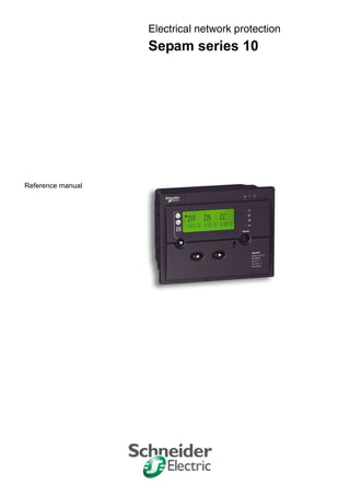
  • 1. Electrical network protectionistribution élect Sepam series 10 Reference manual CÔNG TY CỔ PHẦN THIẾT BỊ ĐIỆN HOÀNG PHƯƠNG ĐC: Số 10, ngõ 44, phố Võ Thị Sáu, P.Thanh Nhàn, Q.Hai Bà Trưng, TP. Hà Nội MST: 0106798886 Tel: 024.3215.1322 Website: Hoangphuong.com.vn Phone: 0944.240.317 / 0975.123.698 / 0961.008.858 Email: Codienhoangphuong@gmail.com
  • 2.
  • 3. SEPED307003 02/2008 3 Table of Contents Safety Information . . . . . . . . . . . . . . . . . . . . . . . . . . . . . . . . . . . . . . . . . . . . . . . . . .7 About the Book . . . . . . . . . . . . . . . . . . . . . . . . . . . . . . . . . . . . . . . . . . . . . . . . . . . . .9 Chapter 1 Presentation . . . . . . . . . . . . . . . . . . . . . . . . . . . . . . . . . . . . . . . . . . . . . . . . . . . . . .11 Introduction . . . . . . . . . . . . . . . . . . . . . . . . . . . . . . . . . . . . . . . . . . . . . . . . . . . . . . . . . . . . . . . . . . . . . . 12 Standard Operation. . . . . . . . . . . . . . . . . . . . . . . . . . . . . . . . . . . . . . . . . . . . . . . . . . . . . . . . . . . . . . . . 15 Identification . . . . . . . . . . . . . . . . . . . . . . . . . . . . . . . . . . . . . . . . . . . . . . . . . . . . . . . . . . . . . . . . . . . . . 18 Chapter 2 Installation. . . . . . . . . . . . . . . . . . . . . . . . . . . . . . . . . . . . . . . . . . . . . . . . . . . . . . . .21 Safety Precautions . . . . . . . . . . . . . . . . . . . . . . . . . . . . . . . . . . . . . . . . . . . . . . . . . . . . . . . . . . . . . . . . 22 Precautions . . . . . . . . . . . . . . . . . . . . . . . . . . . . . . . . . . . . . . . . . . . . . . . . . . . . . . . . . . . . . . . . . . . . . . 23 Equipment Receipt and Identification . . . . . . . . . . . . . . . . . . . . . . . . . . . . . . . . . . . . . . . . . . . . . . . . . . 24 Mounting/Assembly. . . . . . . . . . . . . . . . . . . . . . . . . . . . . . . . . . . . . . . . . . . . . . . . . . . . . . . . . . . . . . . . 25 Connectors . . . . . . . . . . . . . . . . . . . . . . . . . . . . . . . . . . . . . . . . . . . . . . . . . . . . . . . . . . . . . . . . . . . . . . 27 Connection Diagrams . . . . . . . . . . . . . . . . . . . . . . . . . . . . . . . . . . . . . . . . . . . . . . . . . . . . . . . . . . . . . . 30 Connecting Current Transformers (CTs) . . . . . . . . . . . . . . . . . . . . . . . . . . . . . . . . . . . . . . . . . . . . . . . . 38 Connecting a Core Balance CT. . . . . . . . . . . . . . . . . . . . . . . . . . . . . . . . . . . . . . . . . . . . . . . . . . . . . . . 40 Connecting the Logic Inputs and Output Relays . . . . . . . . . . . . . . . . . . . . . . . . . . . . . . . . . . . . . . . . . . 42 Connecting the Communication Port. . . . . . . . . . . . . . . . . . . . . . . . . . . . . . . . . . . . . . . . . . . . . . . . . . . 43 Dimensioning the CTs. . . . . . . . . . . . . . . . . . . . . . . . . . . . . . . . . . . . . . . . . . . . . . . . . . . . . . . . . . . . . . 44 CSH120, CSH200 and GO110 Core Balance CTs . . . . . . . . . . . . . . . . . . . . . . . . . . . . . . . . . . . . . . . . 46 Chapter 3 Use . . . . . . . . . . . . . . . . . . . . . . . . . . . . . . . . . . . . . . . . . . . . . . . . . . . . . . . . . . . . . .51 User-Machine Interface . . . . . . . . . . . . . . . . . . . . . . . . . . . . . . . . . . . . . . . . . . . . . . . . . . . . . . . . . . . . . 52 Operation. . . . . . . . . . . . . . . . . . . . . . . . . . . . . . . . . . . . . . . . . . . . . . . . . . . . . . . . . . . . . . . . . . . . . . . . 54 Setting . . . . . . . . . . . . . . . . . . . . . . . . . . . . . . . . . . . . . . . . . . . . . . . . . . . . . . . . . . . . . . . . . . . . . . . . . . 56 List of Sepam Series 10 N Screens . . . . . . . . . . . . . . . . . . . . . . . . . . . . . . . . . . . . . . . . . . . . . . . . . . . 60 List of Sepam Series 10 B Screens . . . . . . . . . . . . . . . . . . . . . . . . . . . . . . . . . . . . . . . . . . . . . . . . . . . 63 List of Sepam Series 10 A Screens . . . . . . . . . . . . . . . . . . . . . . . . . . . . . . . . . . . . . . . . . . . . . . . . . . . 67 Chapter 4 Functions and parameters. . . . . . . . . . . . . . . . . . . . . . . . . . . . . . . . . . . . . . . . . . .73 General Principle. . . . . . . . . . . . . . . . . . . . . . . . . . . . . . . . . . . . . . . . . . . . . . . . . . . . . . . . . . . . . . . . . . 74 Definition of Symbols. . . . . . . . . . . . . . . . . . . . . . . . . . . . . . . . . . . . . . . . . . . . . . . . . . . . . . . . . . . . . . . 75 Phase CT Ratio. . . . . . . . . . . . . . . . . . . . . . . . . . . . . . . . . . . . . . . . . . . . . . . . . . . . . . . . . . . . . . . . . . . 77 Earth CT Ratio or Core balance CT Rating. . . . . . . . . . . . . . . . . . . . . . . . . . . . . . . . . . . . . . . . . . . . . . 78 Network Frequency . . . . . . . . . . . . . . . . . . . . . . . . . . . . . . . . . . . . . . . . . . . . . . . . . . . . . . . . . . . . . . . . 79 Phase Overcurrent Protection (ANSI 50-51) . . . . . . . . . . . . . . . . . . . . . . . . . . . . . . . . . . . . . . . . . . . . . 80 Earth Fault Protection (ANSI 50N-51N) . . . . . . . . . . . . . . . . . . . . . . . . . . . . . . . . . . . . . . . . . . . . . . . . 84 Overcurrent Protection Tripping Curves . . . . . . . . . . . . . . . . . . . . . . . . . . . . . . . . . . . . . . . . . . . . . . . . 90 Phase Overcurrent Cold Load Pick-Up (Cold Load Pick-Up I) . . . . . . . . . . . . . . . . . . . . . . . . . . . . . . 102 Earth Fault Cold Load Pick-Up (Cold Load Pick-Up Io). . . . . . . . . . . . . . . . . . . . . . . . . . . . . . . . . . . . 105 Thermal Overload Protection (ANSI 49 RMS) . . . . . . . . . . . . . . . . . . . . . . . . . . . . . . . . . . . . . . . . . . 109 Circuit Breaker Control . . . . . . . . . . . . . . . . . . . . . . . . . . . . . . . . . . . . . . . . . . . . . . . . . . . . . . . . . . . . 117 External Trip . . . . . . . . . . . . . . . . . . . . . . . . . . . . . . . . . . . . . . . . . . . . . . . . . . . . . . . . . . . . . . . . . . . . 120 Logic Discrimination (ANSI 68) . . . . . . . . . . . . . . . . . . . . . . . . . . . . . . . . . . . . . . . . . . . . . . . . . . . . . . 121 Phase Current Measurement . . . . . . . . . . . . . . . . . . . . . . . . . . . . . . . . . . . . . . . . . . . . . . . . . . . . . . . 125 Earth Fault Current Measurement. . . . . . . . . . . . . . . . . . . . . . . . . . . . . . . . . . . . . . . . . . . . . . . . . . . . 126 Phase Peak Demand Current Values . . . . . . . . . . . . . . . . . . . . . . . . . . . . . . . . . . . . . . . . . . . . . . . . . 127 Last Fault Record . . . . . . . . . . . . . . . . . . . . . . . . . . . . . . . . . . . . . . . . . . . . . . . . . . . . . . . . . . . . . . . . 128 Time-Tagged Record of Last 5 Events . . . . . . . . . . . . . . . . . . . . . . . . . . . . . . . . . . . . . . . . . . . . . . . . 129 Operating Language . . . . . . . . . . . . . . . . . . . . . . . . . . . . . . . . . . . . . . . . . . . . . . . . . . . . . . . . . . . . . . 130 Number of Phase Currents Displayed. . . . . . . . . . . . . . . . . . . . . . . . . . . . . . . . . . . . . . . . . . . . . . . . . 131 Communication . . . . . . . . . . . . . . . . . . . . . . . . . . . . . . . . . . . . . . . . . . . . . . . . . . . . . . . . . . . . . . . . . . 132 Trip Circuit Supervision (TCS). . . . . . . . . . . . . . . . . . . . . . . . . . . . . . . . . . . . . . . . . . . . . . . . . . . . . . . 135 Date and Time. . . . . . . . . . . . . . . . . . . . . . . . . . . . . . . . . . . . . . . . . . . . . . . . . . . . . . . . . . . . . . . . . . . 137
  • 4. 4 SEPED307003 02/2008 Voltage Applied to the Logic Inputs . . . . . . . . . . . . . . . . . . . . . . . . . . . . . . . . . . . . . . . . . . . . . . . . . . . 138 Operation of the Local/Remote Check. . . . . . . . . . . . . . . . . . . . . . . . . . . . . . . . . . . . . . . . . . . . . . . . . 139 Password . . . . . . . . . . . . . . . . . . . . . . . . . . . . . . . . . . . . . . . . . . . . . . . . . . . . . . . . . . . . . . . . . . . . . . . 140 Display the Status of the Logic Inputs . . . . . . . . . . . . . . . . . . . . . . . . . . . . . . . . . . . . . . . . . . . . . . . . . 141 Display the Status of the Output Relays . . . . . . . . . . . . . . . . . . . . . . . . . . . . . . . . . . . . . . . . . . . . . . . 142 Watchdog Relay. . . . . . . . . . . . . . . . . . . . . . . . . . . . . . . . . . . . . . . . . . . . . . . . . . . . . . . . . . . . . . . . . . 143 Indicator LEDs on the Front Panel . . . . . . . . . . . . . . . . . . . . . . . . . . . . . . . . . . . . . . . . . . . . . . . . . . . . 144 Fault Acknowledgement. . . . . . . . . . . . . . . . . . . . . . . . . . . . . . . . . . . . . . . . . . . . . . . . . . . . . . . . . . . . 146 Chapter 5 Custom operating mode . . . . . . . . . . . . . . . . . . . . . . . . . . . . . . . . . . . . . . . . . . . 147 Introduction . . . . . . . . . . . . . . . . . . . . . . . . . . . . . . . . . . . . . . . . . . . . . . . . . . . . . . . . . . . . . . . . . . . . . 148 Sepam Series 10 N - Customizing the Output Relays. . . . . . . . . . . . . . . . . . . . . . . . . . . . . . . . . . . . . 149 Sepam Series 10 N - Customizing the Fault LED . . . . . . . . . . . . . . . . . . . . . . . . . . . . . . . . . . . . . . . . 151 Sepam Series 10 B - Customizing the Output Relays . . . . . . . . . . . . . . . . . . . . . . . . . . . . . . . . . . . . . 152 Sepam Series 10 B - Customizing the Fault LEDs . . . . . . . . . . . . . . . . . . . . . . . . . . . . . . . . . . . . . . . 154 Sepam Series 10 A - Customizing the Output Relays . . . . . . . . . . . . . . . . . . . . . . . . . . . . . . . . . . . . . 155 Sepam Series 10 A - Customizing the Logic Inputs . . . . . . . . . . . . . . . . . . . . . . . . . . . . . . . . . . . . . . 157 Sepam Series 10 A - Customizing the Fault LEDs . . . . . . . . . . . . . . . . . . . . . . . . . . . . . . . . . . . . . . . 158 Sepam Series 10 A - Customizing Logic Discrimination . . . . . . . . . . . . . . . . . . . . . . . . . . . . . . . . . . . 159 Chapter 6 Circuit breaker control and reliability . . . . . . . . . . . . . . . . . . . . . . . . . . . . . . . . 161 General Principle . . . . . . . . . . . . . . . . . . . . . . . . . . . . . . . . . . . . . . . . . . . . . . . . . . . . . . . . . . . . . . . . . 162 Circuit Breaker Control in Standard Mode . . . . . . . . . . . . . . . . . . . . . . . . . . . . . . . . . . . . . . . . . . . . . . 164 Circuit Breaker Control in Custom Mode . . . . . . . . . . . . . . . . . . . . . . . . . . . . . . . . . . . . . . . . . . . . . . . 166 Operation of the Self-test System . . . . . . . . . . . . . . . . . . . . . . . . . . . . . . . . . . . . . . . . . . . . . . . . . . . . 168 Chapter 7 Communication . . . . . . . . . . . . . . . . . . . . . . . . . . . . . . . . . . . . . . . . . . . . . . . . . . 169 7.1 Modbus Protocol . . . . . . . . . . . . . . . . . . . . . . . . . . . . . . . . . . . . . . . . . . . . . . . . . . . . . . . . . . . . . . . . . 170 Presentation. . . . . . . . . . . . . . . . . . . . . . . . . . . . . . . . . . . . . . . . . . . . . . . . . . . . . . . . . . . . . . . . . . . . . 171 Modbus Protocol . . . . . . . . . . . . . . . . . . . . . . . . . . . . . . . . . . . . . . . . . . . . . . . . . . . . . . . . . . . . . . . . . 172 Commissioning and Diagnosis. . . . . . . . . . . . . . . . . . . . . . . . . . . . . . . . . . . . . . . . . . . . . . . . . . . . . . . 174 Access to Data. . . . . . . . . . . . . . . . . . . . . . . . . . . . . . . . . . . . . . . . . . . . . . . . . . . . . . . . . . . . . . . . . . . 176 Data Coding. . . . . . . . . . . . . . . . . . . . . . . . . . . . . . . . . . . . . . . . . . . . . . . . . . . . . . . . . . . . . . . . . . . . . 177 Synchronization, Data, Metering, Network Diagnosis and Test Zones . . . . . . . . . . . . . . . . . . . . . . . . 178 Remote Control Zone. . . . . . . . . . . . . . . . . . . . . . . . . . . . . . . . . . . . . . . . . . . . . . . . . . . . . . . . . . . . . . 180 Status Condition and Remote Indication Zone . . . . . . . . . . . . . . . . . . . . . . . . . . . . . . . . . . . . . . . . . . 181 Time-Tagged Events . . . . . . . . . . . . . . . . . . . . . . . . . . . . . . . . . . . . . . . . . . . . . . . . . . . . . . . . . . . . . . 184 Date and Time-Setting and Synchronization . . . . . . . . . . . . . . . . . . . . . . . . . . . . . . . . . . . . . . . . . . . . 187 Read Sepam Identification. . . . . . . . . . . . . . . . . . . . . . . . . . . . . . . . . . . . . . . . . . . . . . . . . . . . . . . . . . 188 7.2 IEC 60870-5-103 protocol . . . . . . . . . . . . . . . . . . . . . . . . . . . . . . . . . . . . . . . . . . . . . . . . . . . . . . . . . . 190 Presentation. . . . . . . . . . . . . . . . . . . . . . . . . . . . . . . . . . . . . . . . . . . . . . . . . . . . . . . . . . . . . . . . . . . . . 191 IEC 60870-5-103 Standard . . . . . . . . . . . . . . . . . . . . . . . . . . . . . . . . . . . . . . . . . . . . . . . . . . . . . . . . . 192 IEC 60870-5-103 Protocol Principle . . . . . . . . . . . . . . . . . . . . . . . . . . . . . . . . . . . . . . . . . . . . . . . . . . 193 Commissioning and Diagnosis. . . . . . . . . . . . . . . . . . . . . . . . . . . . . . . . . . . . . . . . . . . . . . . . . . . . . . . 194 Access to Data. . . . . . . . . . . . . . . . . . . . . . . . . . . . . . . . . . . . . . . . . . . . . . . . . . . . . . . . . . . . . . . . . . . 195 Sepam Communication Profile . . . . . . . . . . . . . . . . . . . . . . . . . . . . . . . . . . . . . . . . . . . . . . . . . . . . . . 196 Sepam Data Table . . . . . . . . . . . . . . . . . . . . . . . . . . . . . . . . . . . . . . . . . . . . . . . . . . . . . . . . . . . . . . . . 201 ASDU 1, 2, 5, 9, 20 Frames and Information Coding. . . . . . . . . . . . . . . . . . . . . . . . . . . . . . . . . . . . . . 204 Chapter 8 Commissioning . . . . . . . . . . . . . . . . . . . . . . . . . . . . . . . . . . . . . . . . . . . . . . . . . . 209 Safety Precautions. . . . . . . . . . . . . . . . . . . . . . . . . . . . . . . . . . . . . . . . . . . . . . . . . . . . . . . . . . . . . . . . 210 Principles . . . . . . . . . . . . . . . . . . . . . . . . . . . . . . . . . . . . . . . . . . . . . . . . . . . . . . . . . . . . . . . . . . . . . . . 211 Testing and Metering Equipment Required . . . . . . . . . . . . . . . . . . . . . . . . . . . . . . . . . . . . . . . . . . . . . 212 Energization. . . . . . . . . . . . . . . . . . . . . . . . . . . . . . . . . . . . . . . . . . . . . . . . . . . . . . . . . . . . . . . . . . . . . 213 Validation of the Complete Protection Chain . . . . . . . . . . . . . . . . . . . . . . . . . . . . . . . . . . . . . . . . . . . . 214 Checking Settings . . . . . . . . . . . . . . . . . . . . . . . . . . . . . . . . . . . . . . . . . . . . . . . . . . . . . . . . . . . . . . . . 215 Checking the CT Ratio. . . . . . . . . . . . . . . . . . . . . . . . . . . . . . . . . . . . . . . . . . . . . . . . . . . . . . . . . . . . . 216 Checking the Phase Current Input Connections . . . . . . . . . . . . . . . . . . . . . . . . . . . . . . . . . . . . . . . . . 217 Checking the Earth Fault Current Inputs . . . . . . . . . . . . . . . . . . . . . . . . . . . . . . . . . . . . . . . . . . . . . . . 219 Phase Overcurrent Protection (ANSI 50-51) Test . . . . . . . . . . . . . . . . . . . . . . . . . . . . . . . . . . . . . . . . 221 Earth Fault Protection (ANSI 50N-51N) Test . . . . . . . . . . . . . . . . . . . . . . . . . . . . . . . . . . . . . . . . . . . . 224 ANSI 49 RMS Thermal Overload Protection Test . . . . . . . . . . . . . . . . . . . . . . . . . . . . . . . . . . . . . . . . 228 Checking the Logic Input Connections . . . . . . . . . . . . . . . . . . . . . . . . . . . . . . . . . . . . . . . . . . . . . . . . 230 Operational Commissioning. . . . . . . . . . . . . . . . . . . . . . . . . . . . . . . . . . . . . . . . . . . . . . . . . . . . . . . . . 231 Sepam Test Sheet . . . . . . . . . . . . . . . . . . . . . . . . . . . . . . . . . . . . . . . . . . . . . . . . . . . . . . . . . . . . . . . . 232
  • 5. SEPED307003 02/2008 5 Chapter 9 Maintenance . . . . . . . . . . . . . . . . . . . . . . . . . . . . . . . . . . . . . . . . . . . . . . . . . . . . .235 Preventive Maintenance . . . . . . . . . . . . . . . . . . . . . . . . . . . . . . . . . . . . . . . . . . . . . . . . . . . . . . . . . . . 236 Troubleshooting Assistance. . . . . . . . . . . . . . . . . . . . . . . . . . . . . . . . . . . . . . . . . . . . . . . . . . . . . . . . . 237 Removing Sepam . . . . . . . . . . . . . . . . . . . . . . . . . . . . . . . . . . . . . . . . . . . . . . . . . . . . . . . . . . . . . . . . 239 Replacing the Battery in the Sepam Series 10 A . . . . . . . . . . . . . . . . . . . . . . . . . . . . . . . . . . . . . . . . 240 Chapter 10 Characteristics . . . . . . . . . . . . . . . . . . . . . . . . . . . . . . . . . . . . . . . . . . . . . . . . . . .243 Function Characteristics . . . . . . . . . . . . . . . . . . . . . . . . . . . . . . . . . . . . . . . . . . . . . . . . . . . . . . . . . . . 244 Technical Characteristics. . . . . . . . . . . . . . . . . . . . . . . . . . . . . . . . . . . . . . . . . . . . . . . . . . . . . . . . . . . 251 Environmental Characteristics. . . . . . . . . . . . . . . . . . . . . . . . . . . . . . . . . . . . . . . . . . . . . . . . . . . . . . . 253 Internal Operation . . . . . . . . . . . . . . . . . . . . . . . . . . . . . . . . . . . . . . . . . . . . . . . . . . . . . . . . . . . . . . . . 255
  • 7. SEPED307003 02/2008 7 § Safety Information Important Information NOTICE Read these instructions carefully, and look at the equipment to become familiar with the device before trying to install, operate, or maintain it. The following special messages may appear throughout this documentation or on the equipment to warn of potential hazards or to call attention to information that clarifies or simplifies a procedure. PLEASE NOTE Electrical equipment should be installed, operated, serviced, and maintained only by qualified personnel. No responsibility is assumed by Schneider Electric for any consequences arising out of the use of this material. © 2008 Schneider Electric. All Rights Reserved. The addition of this symbol to a Danger or Warning safety label indicates that an electrical hazard exists, which will result in personal injury if the instructions are not followed. This is the safety alert symbol. It is used to alert you to potential personal injury hazards. Obey all safety messages that follow this symbol to avoid possible injury or death. DANGER indicates an imminently hazardous situation, which, if not avoided, will result in death or serious injury. DANGER WARNING indicates a potentially hazardous situation, which, if not avoided, can result in death, serious in- jury, or equipment damage. WARNING CAUTION indicates a potentially hazardous situation, which, if not avoided, can result in injury or equipment damage. CAUTION
  • 9. SEPED307003 02/2008 9 About the Book At a Glance Document Scope This manual is intended for personnel responsible for installing, commissioning and using Sepam series 10 protection relays. It gives more details than the instruction sheet supplied with the equipment. Validity Note The data and illustrations in this documentation by no means imply any kind of contractual obligation. We reserve the right to modify our products in line with our policy of continuous development. The information given in this document may be modified without notice and must not be interpreted as binding on the part of Schneider Electric. Please contact us if you have any suggestions for improvements or modifications, or if you find any errors in this publication. No part of this document may be reproduced in any form or by any means whatsoever (electronic, mechanical or photocopying) without the prior authorization of Schneider Electric. Product Related Warnings All relevant local safety regulations must be followed when installing and using this product. For safety reasons, and to ensure conformity with the documented system data, only the manufacturer is authorized to repair the components. Failure to comply with this warning can result in injury or equipment damage. User Comments We welcome your comments about this document. You can reach us by e-mail at techpub@schneider-electric.com
  • 10. About the Book 10 SEPED307003 02/2008
  • 11. SEPED307003 02/2008 11 1 Presentation What's in this Chapter? This chapter contains the following topics: Topic Page Introduction 12 Standard Operation 15 Identification 18
  • 12. Sepam Series 10 - Presentation 12 SEPED307003 02/2008 Introduction The Sepam Series 10 Family The Sepam series 10 family of protection relays is designed for the protection and operation of MV/LV utility substations and electrical distribution networks in industrial installations. It comprises three models suitable for normal protection applications involving current measurement: z Sepam series 10 N, for earth fault protection z Sepam series 10 B, for phase, earth fault and thermal overload protection z Sepam series 10 A, for phase, earth fault and thermal overload protection, which may require logic inputs and a communication port Example: Sepam series 10 A MainAdvantages of Sepam Sepam is easily installed in a switchboard: z It is compact. z It is held in place in the switchboard by catches which are locked and unlocked from the front. z The connection terminals are clearly identified. Sepam is quick to commission: z It comes with default parameters. z Its settings are entered on the front panel by means of its display and well-designed keypad. z It can be commissioned without using a PC. Sepam makes it easy to operate substations: z It has numerous customization options so that it can be adapted to specific operating constraints. z Its display unit can display screens in several languages. z It indicates tripping explicitly and spontaneously. Sepam is a robust product that is easy to maintain: z The case is made of insulated plastic. z The unit can withstand harsh environments: z Front panel degree of protection: IP54 z Range of operating temperatures: –40 to +70 °C (–40 to +158 °F) z The current input connector can be disconnected while on load. Sepam Series 10 N Applications Sepam series 10 N units are suitable for the following applications: z Protection against earth faults for feeders protected against phase-to-phase short-circuits by fuses z Protection of the transformer neutral point Sepam Series 10 B Applications Sepam series 10 B units are suitable for the following applications: z Protection of substation incomers and feeders z Protection of MV/LV transformers They offer the following protection functions: z Phase overcurrent protection z Earth fault protection z Thermal overload protection
  • 13. Sepam Series 10 - Presentation SEPED307003 02/2008 13 Sepam Series 10 A Applications Sepam series 10 A units are suitable for the following applications: z Protection of substation incomers and feeders z Protection of MV/LV transformers They offer the following main functions: z Phase overcurrent protection z Earth fault protection z Thermal overload protection z Trip circuit supervision (TCS) z Logic discrimination z External trip z Communication for remote operation Selection Table The selection table lists the functions performed by the various Sepam series 10 models in standard operation. The customization options for these functions are described in the Custom Operation chapter. • Function available in standard mode •• Function available in standard mode depending on the Sepam type ••• Function available in custom mode Function ANSI Code Sepam Series 10 N B A Earth fault protection Standard 50N-51N 50G-51G •• •• •• Sensitive •• •• Very sensitive •• •• •• Phase overcurrent protection 50-51 • • Thermal overload protection 49 RMS • • Phase overcurrent cold load pick-up • • Earth fault cold load pick-up • • Circuit breaker trip lockout 86 • • • Tripping annunciation • • • Trip circuit supervision • Logic discrimination - Send blocking input 68 ••• ••• • Logic discrimination - Receive blocking input 68 ••• External trip • Communication via Modbus protocol or IEC 60870-5-103 • Circuit breaker remote control • Customized operation of output relays and fault LEDs ••• ••• ••• Customized assignment of the logic inputs ••• Earth fault current measurement • • • Phase current measurement • • Phase peak demand current values • • Record of the last fault • • Time-tagged record of the last 5 events • Watchdog ••• ••• •
  • 14. Sepam Series 10 - Presentation 14 SEPED307003 02/2008 Earth Fault Protection To protect networks against phase-to-earth faults, choose the earth fault protection sensitivity level from one of three values. The sensors to be used and the set point setting range depend on the chosen sensitivity: Resources The table below lists the Sepam resources: Power Supply Voltage The Sepam power supply voltage can be DC or AC. Three power supply voltage ranges are available, as indicated in the table below: Sepam series 10 A relays powered by 220...250 V DC have high-set logic inputs. Operating Modes There are two possible operating modes for the output relays, the fault LEDs on the front panel and, in the case of Sepam series 10 A, the logic inputs: z Standard operating mode is operation resulting from the pre-assignment of the output relays, the fault LEDs on the front panel and the logic inputs. Sepam series 10 relays are delivered from the factory in this mode. z Custom operating mode is used, if necessary, to modify operation of the output relays, the fault LEDs on the front panel and the logic inputs. Circuit Breaker Control Sepam relays are compatible with the following types of circuit breaker trip: z Shunt trip coils z Undervoltage trip coils Sensitivity Sensor Setting range Standard 3 phase CTs or 1 earth CT, at primary rated current Ino 0.1...24 Ino Sensitive 3 phase CTs or 1 earth CT, at primary rated current Ino 0.01...2.4 Ino Very sensitive CSH120, CSH200 or GO110 specific core balance CT, with ratio 470/1 0.2...240 A primary, i.e. 0.0004...0.5 Ino Inputs/Outputs Sepam Series 10 N Sepam Series 10 B Sepam Series 10 A Earth fault current inputs 1 1 1 Phase current inputs 0 2 or 3 3 Output relays 3 3 7 Logic inputs 0 0 4 Communication port 0 0 1 Power supply Sepam Series 10 N Sepam Series 10 B Sepam Series 10 A 24...125 V DC or 100...120 V AC • • • 110...250 V DC or 100...240 V AC • • • 220...250 V DC – – •
  • 15. Sepam Series 10 - Presentation SEPED307003 02/2008 15 Standard Operation Introduction The mimic diagrams below show the functional chains for each Sepam model in standard operating mode with: z Connection of the earth fault current input to an earth CT, for example z Connection of the phase current inputs, if necessary z Connection of the protective earth Mimic Diagram of Sepam Series 10 N Operation Output Relays Assignment O1 Circuit breaker tripping O2 Circuit breaker trip lockout O3 Tripping annunciation IA IB IC B 21 11 22 12 O1 O2 O3 1 A 2 3 4 5 6 7 8 9 10 11 12 13 14 Io Io>> Io> I > S R CT 1A/5A 23 13 24 14 25 15 Reset S R ≥1 ≥1
  • 16. Sepam Series 10 - Presentation 16 SEPED307003 02/2008 Mimic Diagram of Sepam Series 10 B Operation Output Relays Assignment O1 Circuit breaker tripping O2 Circuit breaker trip lockout O3 Tripping annunciation IA IB IC IA IB IC B 21 11 22 12 O1 O2 O3 1 A 2 3 4 5 6 7 8 9 10 11 12 13 14 max Io 49 RMS I> I>> Io>> Io> S R S R I > S R S R I > CT 1A/5A 23 13 24 14 25 15 Reset ≥1 ≥1 ≥1
  • 17. Sepam Series 10 - Presentation SEPED307003 02/2008 17 Mimic Diagram of Sepam Series 10 A Operation The mimic diagram for the Sepam series 10 A also represents the connection of logic inputs I1 and I2: Output Relays Assignment O1 Circuit breaker tripping O2 Circuit breaker trip lockout O3 Tripping annunciation O4 Circuit breaker closing via the communication O5 Send blocking input O6 TCS annunciation O7 Watchdog Logic Inputs Assignment I1 Open circuit breaker I2 Closed circuit breaker I3 External trip I4 Local/Remote IA IB IC IA IB IC B 21 11 22 12 O1 O2 O3 1 A 2 3 4 5 6 7 8 9 10 11 12 13 14 max Io 49 RMS I> I>> ≥1 Io>> Io> 1 2 3 4 C C S D0 D1 I2 I1 D 1 2 3 4 5 TCS O5 O6 O4 D 13 14 15 16 17 18 S R S R I > I4 I3 6 7 8 9 D S R Reset S R Ext RS 485 I> 68 O7 10 11 12 watchdog CT 1A/5A 23 13 24 14 25 15 S R COM Local / Remote Reset Open Close 1 ≥ ≥1 ≥1 ≥1
  • 18. Sepam Series 10 - Presentation 18 SEPED307003 02/2008 Identification Identification Code The identification code for a Sepam series 10 is an alphanumeric code that defines the Sepam's main functions. It consists of several fields: Family Sepam series 10 Model N: Earth fault protection B: Phase and earth fault overcurrent protection A: Phase and earth fault overcurrent protection, logic inputs and communication port Number of current inputs 1: 1 earth current input 3: 2 phase current inputs + 1 earth current input 4: 3 phase current inputs + 1 earth current input Sensitivity of earth fault protection 1: Standard (0.1...24 Ino) 2: Sensitive (0.01...2.4 Ino) 3: Very sensitive (0.2...24 A and 2...240 A) Power supply A: 24...125 V DC and 100...120 V AC E: 110...250 V DC and 100...240 V AC F: 220...250 V DC and high-set logic inputs Sepam Series 10 References (1) Sepam certified DK5600 (Italy) (2) Sepam certified GOST (Russia) Spare Part References Sepam Series 10 • • • • N B A 1 2 3 A E F 1 3 4 Model Number of Current Inputs Sensitivity of Earth Fault Protection Power Supply A E F 24...125 V DC 100...120 V AC 110...250 V DC 100...240 V AC 220...250 V DC Series 10 N 1 1: Standard REL59817 REL59819 – 3: Very sensitive REL59818 REL59820 – Series 10 B 3 1: Standard REL59800 REL59801 – 4 1: Standard REL59802 REL59805 – 2: Sensitive REL59803 REL59806 REL59827 (2) – 3: Very sensitive REL59804 REL59823 (1) REL59807 REL59824 (1) – Series 10 A 4 1: Standard REL59808 REL59811 REL59814 2: Sensitive REL59809 REL59812 REL59828 (2) REL59815 REL59829 ( 2) 3: Very sensitive REL59810 REL59825 (1) REL59813 REL59826 (1) REL59816 Reference Description REL59798 CCA680 - Pack of spare connectors (one of each connector A, B, C and D)
  • 19. Sepam Series 10 - Presentation SEPED307003 02/2008 19 Accessory References Reference Description 59635 CSH120 - Closed core balance CT, diameter 120 mm (4.7 in) 59636 CSH200 - Closed core balance CT, diameter 196 mm (7.7 in) 50134 GO110 - Opening core balance CT, diameter 110 mm (4.3 in) VW3A8306DR Line termination resistor (150 Ω)
  • 20. Sepam Series 10 - Presentation 20 SEPED307003 02/2008
  • 21. SEPED307003 02/2008 21 2 Installation What's in this Chapter? This chapter contains the following topics: Topic Page Safety Precautions 22 Precautions 23 Equipment Receipt and Identification 24 Mounting/Assembly 25 Connectors 27 Connection Diagrams 30 Connecting Current Transformers (CTs) 38 Connecting a Core Balance CT 40 Connecting the Logic Inputs and Output Relays 42 Connecting the Communication Port 43 Dimensioning the CTs 44 CSH120, CSH200 and GO110 Core Balance CTs 46
  • 22. Sepam Series 10 - Installation 22 SEPED307003 02/2008 Safety Precautions Before Starting You are responsible for compliance with all the existing international and national electrical codes concerning protective earthing of any device. You should also carefully read the safety precautions described below. These instructions must be followed strictly when installing, servicing or repairing electrical equipment. HAZARD OF ELECTRIC SHOCK, ELECTRIC ARC, BURNS OR EXPLOSION z Only qualified personnel should install this equipment. Such work should be performed only after reading this entire set of instructions. z NEVER work alone. z Turn off all power supplying this equipment before working on or inside it. z Always use a properly rated voltage sensing device to confirm that all power is off. z Before performing visual inspections, tests, or maintenance on this equipment: z Disconnect all sources of electric power. z Assume that all circuits are live until they have been completely de-energized, tested and tagged. z Pay particular attention to the design of the power system. Consider all sources of power, including the possibility of backfeeding. z Beware of potential hazards, wear personal protective equipment, and carefully inspect the work area for tools and objects that may have been left inside the equipment. z The successful operation of Sepam depends upon proper installation, setting, and operation. z Setting the Sepam relay requires relevant expertise in the field of electrical network protection. Only competent people who have this expertise are allowed to set this product. Failure to follow these instructions will result in death or serious injury. HAZARD OF DAMAGE TO SEPAM z Before performing Dielectric (Hi-Pot) or Megger testing on any equipment in which the relay is installed, disconnect all input and output wires to the relay. High voltage testing may damage electronic components contained in the relay. z Do not open the Sepam case. The Sepam relay contains components that are susceptible to electrostatic discharge. It is assembled in specially equipped premises. The only permitted operation is the removal of the depleted battery from its compartment on a Sepam series 10 A relay. Failure to follow these instructions can result in injury or equipment damage. DANGER CAUTION
  • 23. Sepam Series 10 - Installation SEPED307003 02/2008 23 Precautions Introduction Sepam relays are supplied in one of the following ways: z Individually packaged z Installed in a cubicle The transport, handling and storage precautions for Sepam relays vary depending on which of these two methods is used. Sepam in its Original Packaging z Transport Sepam relays can be shipped to any destination by all suitable means of transport, without taking any additional precautions. z Handling Sepam relays can be handled without any particular care and can withstand being dropped from a height of 1 m (3.28 ft). z Storage A Sepam relay can be stored in its original packaging in a location with the following environmental characteristics: z Temperature: –40...+70 °C (or –40...+158 °F) z Humidity ≤ 90% z Storage is limited to a maximum of one month if the relative humidity is higher than 93% and the temperature higher than +40 °C (or +104 °F). For more information, refer to Climatic Withstand, p. 254. If the relays are to be stored for an extended period, we recommend the following: z Do not unpack the Sepam prior to its intended period of use. z Check the environment and the condition of the packaging annually. Once the Sepam relay has been unpacked, it should be energized as soon as possible. Sepam Installed in a Cubicle z Transport Sepam relays can be transported by all suitable means of transport in the usual conditions for cubicles. Storage conditions should be taken into consideration for a long period of transport. z Handling If the cubicle is dropped, check the Sepam’s condition by visual inspection and energizing. z Storage We recommend keeping the cubicle protective packaging for as long as possible. Sepam relays, like all electronic units, should not be stored in a damp environment for more than a month. They should be energized as quickly as possible. If this is not possible, the cubicle reheating system should be activated. Sepam Used in a Damp Environment The temperature/relative humidity factors must be compatible with the Sepam relay's environmental withstand characteristics: Refer to Climatic Withstand, p. 254. If the conditions of use are outside the normal zone, special arrangements should be made before commissioning, such as air conditioning of the premises. Sepam Used in a Polluted Environment An industrial atmosphere contaminated by the presence of chlorine, hydrofluoric acid, sulfur, solvents, etc. can cause corrosion of the electronic components. In this case, environmental control arrangements should be made (such as closed, pressurized premises with filtered air, etc.) before commissioning. The effect of corrosion on Sepam relays has been tested according to the IEC 60068-2-60 standard under the following "2-gas" test conditions: z 21 days' duration z 25°C (or 77°F), 75% relative humidity z 0.5 ppm H2S, 1 ppm SO2
  • 24. Sepam Series 10 - Installation 24 SEPED307003 02/2008 Equipment Receipt and Identification Equipment Receipt The Sepam unit is shipped in a cardboard box which protects it against any knocks received in transport. On receipt, check that the packaging has not been damaged. If it has, note any anomaly on the delivery slip and inform your supplier. Package Contents The box contains the following items: z A Sepam relay without connectors z A settings sheet to be completed and kept near the Sepam relay z An instruction sheet providing the main information about installation and use z A certificate of conformity z 2 bags containing the connectors Identification Label The identification label on the front panel is used to identify the Sepam: 1 Identification code 2 Reference 3 Power supply voltage 4 Serial number For the meaning of the identification codes, refer to Identification, p. 18. Check After Unpacking Make sure that the Sepam relay supplied corresponds to the product ordered. In particular, check that the power supply voltage is the correct one for your installation. Sepam series 10 A 42A REL59809 24-125V= 100-120V~ SN 814323 3 2 4 1
  • 25. Sepam Series 10 - Installation SEPED307003 02/2008 25 Mounting/Assembly Introduction Sepam relays weigh 1.3 kg (2.87 lb) maximum and are flush-mounted in a mounting plate 1.5 to 4 mm (0.06 to 0.16 in) thick. They are designed to be mounted indoors. To ensure a waterproof seal, the surface of the panel must be smooth and solid. Dimensions Cut-out Cut out the mounting plate as indicated: 140 5.51 180 7.09 123 4.84 16 0.63 mm in HAZARD OF CUTS Trim the edges of the cut-out plates to remove any jagged edges. Failure to follow these instructions can result in injury or equipment damage. mm in 161 129 CAUTION
  • 26. Sepam Series 10 - Installation 26 SEPED307003 02/2008 Installing the Sepam The Sepam relay is held in place by 2 catches on the sides, behind the front panel: Step Action Illustration 1 Mark the catches (1). 2 Insert the Sepam unit through the cut-out. 3 Open the settings protective flap. 4 Tighten the screws as indicated using a no. 2 Pozidriv® screwdriver (maximum tightening torque: 2 N•m/17.7 lb-in). 5 Check the position of the catches at the rear. – 6 Close the settings protective flap. – 1
  • 27. Sepam Series 10 - Installation SEPED307003 02/2008 27 Connectors Introduction All the Sepam connectors can be accessed on the rear panel. They are removable and are attached to the Sepam casing with two screws. The connectors are supplied separately: fix them in place using a flat blade screwdriver. Identification of the Connectors on the Rear Panel A Connector for the auxiliary power supply and output relays O1 to O3 B Connector for the phase and earth fault current inputs C 2-wire RS 485 communication port (Sepam series 10 A only) D Connector for output relays O4 to O7 and logic inputs I1 to I4 (Sepam series 10 A only) Sepam Series 10 N and Series 10 B Sepam Series 10 A B A 8 B A C D RS 485 8 8 Protective earth
  • 28. Sepam Series 10 - Installation 28 SEPED307003 02/2008 Connector Wiring Remark: Connectors A and D supplied with the Sepam can be replaced by the ring lug connectors indicated in the table below. These connectors are not supplied and should be ordered separately. Shorting Connector Connector B for connecting the current sensors (current transformers and core balance CT) is a shorting connector. It can be disconnected while on load: disconnecting it does not open the secondary circuit on the current sensors. Connector A Connections Ref. Wiring Type of Terminal Screwdriver Tightening Torque B z Wire 1.5...6 mm2 (AWG 16...10) z 2 lugs with internal diameter 4 mm (0.16 in) maximum M4 screw Pozidriv no. 2 1.2...1.5 N•m (10.6...13 lb-in) A, C and D z Wiring without fittings: z 1 wire: 0.2..2.5 mm2 (AWG 24...12) z 2 wires: 0.2...1 mm2 (AWG 24...18) z Stripped length: 8...10 mm (0.31...0.39 in) z Wiring with Telemecanique fittings: z 1 wire 1.5 mm2 (AWG 16) with DZ5CE015D fitting z 1 wire 2.5 mm2 (AWG 12) with DZ5CE025D fitting z 2 wires 1 mm2 (AWG 18) with DZ5CE010D fitting z Stripped length: 8 mm (0.31 in) M2.5 screw 2.5 mm flat blade (0.09 in) 0.4...0.5 N•m (3.5...4.4 lb-in) z Green-yellow wire 6 mm2 (AWG 10) z Lug with internal diameter 4 mm (0.16 in) maximum z Length < 0.50 m (20 in) M4 screw Pozidriv no. 2 1.2...1.5 N•m (10.6...13 lb-in) Ref. Wiring Type of Terminal Connector Reference A 0.5..2.5 mm2 wire (AWG 22...12) M3.5 screw Pitch Beau® EuroMate™ Molex no. 0399400414 D 0.5..2.5 mm2 wire (AWG 22...12) M3.5 screw Pitch Beau® EuroMate™ Molex no. 0399400418 Diagram Terminal Data Item Connected 1-2 Auxiliary power supply z AC power supply voltage on terminals 1 and 2 z DC power supply voltage z Terminal 1: positive polarity z Terminal 2: negative polarity 3-4 and 5-6 Output relay O1 z Terminals 3-4: Normally open contact (NO) z Terminals 5-6: Normally closed contact (NC) 7-8 and 9-10 Output relay O2 z Terminals 7-8: Normally open contact (NO) z Terminals 9-10: Normally closed contact (NC) 11-12 and 13-14 Output relay O3 z Terminals 11-12: Normally open contact (NO) z Terminals 13-14: Normally closed contact (NC) O1 O2 O3 1 A 2 3 4 5 6 7 8 9 10 11 12 13 14
  • 29. Sepam Series 10 - Installation SEPED307003 02/2008 29 Connector B Connections Connector C Connections Connector C is the 2-wire RS 485 communication port on Sepam series 10 A relays: Connector D Connections The additional logic inputs and output relays for Sepam series 10 A relays are connected to connector D: Diagram Terminal Data Item Connected 15-25 Phase A current input 14-24 Phase B current input 13-23 Phase C current input 12-22 Earth fault current input Io z For the standard and sensitive earth fault protection functions z For the very sensitive earth fault protection function (2 - 240 A rating) 11-21 Earth fault current input Io for the very sensitive earth fault protection function only (0.2 - 24 A rating) A IA IB IC B 23 13 24 14 25 15 Io 2-240 A 21 22 12 0.2-24 A 11 Io Diagram Terminal Data Item Connected 1 C: Common (communication interface 0V) 2 S: Shielding (terminal connected to the Sepam earthing terminal) 3 D0: Terminal to be connected to terminal A (or L–) of the supervisor port 4 D1: Terminal to be connected to terminal B (or L+) of the supervisor port RS 485 1 2 3 4 C C S D0 D1 Diagram Terminal Data Item Connected 1-2 Logic input I1 3 Terminal not used 4-5 Logic input I2 6-7 Logic input I3 8-9 Logic input I4 10-11-12 Output relay O7: Watchdog z Terminal 12: Common z Terminal 11: Normally open contact (NO) z Terminal 10: Normally closed contact (NC) 13-14 Output relay O6, normally open contact (NO) 15-16 Output relay O5, normally open contact (NO) 17-18 Output relay O4, normally open contact (NO) I4 I2 I1 I3 O5 O6 O4 O7 D 1 2 3 4 5 6 7 8 9 10 11 12 13 14 15 16 17 18
  • 30. Sepam Series 10 - Installation 30 SEPED307003 02/2008 Connection Diagrams General Safety Precautions Earthing The Sepam earth terminal is a protective earth. It should be connected to the cubicle grounding with an earthing wire. The characteristics of the earthing wire are as follows: z Wire: green-yellow 6 mm2 (AWG 10) z Maximum length: 0.5 m (20 in) HAZARD OF ELECTRIC SHOCK, ELECTRIC ARC OR BURNS z Only qualified personnel should install this equipment. Such work should be performed only after reading this entire set of instructions and checking the technical characteristics of the device. z NEVER work alone. z Turn off all power supplying this equipment before working on or inside it. Consider all sources of power, including the possibility of backfeeding. z Always use a properly rated voltage sensing device to confirm that all power is off. z Wear insulating gloves to avoid any contact with a conductor that has accidentally been energized. z Screw tight all terminals, even those not in use. Failure to follow these instructions will result in death or serious injury. DANGER
  • 31. Sepam Series 10 - Installation SEPED307003 02/2008 31 Sepam Series 10 N 11• Sepam series 10 N 11• relays measure the earth fault current, either: z By 1 earth CT z On the common point of the 3 phase CTs Variant no. 1 Variant no. 2 Earth fault current measured by 1 earth CT Earth fault current measured on the common point of the 3 phase CTs A B C O1 O2 O3 1 A 2 3 4 5 6 7 8 9 10 11 12 13 14 B 21 11 22 12 23 13 24 14 25 15 CT 1A/5A Io A B C O1 O2 O3 1 A 2 3 4 5 6 7 8 9 10 11 12 13 14 B 21 11 22 12 23 13 24 14 25 15 Io
  • 32. Sepam Series 10 - Installation 32 SEPED307003 02/2008 Sepam Series 10 N 13• Sepam series 10 N 13• relays measure the earth fault current using 1 CSH120, CSH200 or GO110 core balance CT, connected to either of the following: z The 2 - 240 A input z The 0.2 - 24 A input CSH120 CSH200 GO110 Io 2-240 A A B C O1 O2 O3 1 A 2 3 4 5 6 7 8 9 10 11 12 13 14 B 21 11 22 12 23 13 24 14 25 15 Io 0.2-24 A
  • 33. Sepam Series 10 - Installation SEPED307003 02/2008 33 Sepam Series 10 B 31• Sepam series 10 B 31• relays measure 3 currents: z 2 phase currents measured by 2 phase CTs z 1 earth fault current measured either: z By 1 earth CT z On the common point of the 3 phase CTs Variant no. 1 Variant no. 2 Earth fault current measured by 1 earth CT Earth fault current measured on the common point of the 3 phase CTs CT 1A/5A IA IC Io A B C O1 O2 O3 1 A 2 3 4 5 6 7 8 9 10 11 12 13 14 B 21 11 22 12 23 13 24 14 25 15 IA IC Io A B C O1 O2 O3 1 A 2 3 4 5 6 7 8 9 10 11 12 13 14 B 21 11 22 12 23 13 24 14 25 15
  • 34. Sepam Series 10 - Installation 34 SEPED307003 02/2008 Sepam Series 10 B 41• and Series 10 B 42• Sepam series 10 B 41• and series 10 B 42• relays measure the following currents: z Phase currents measured by 2 or 3 phase CTs z 1 earth fault current measured either: z By 1 earth CT z On the common point of the 3 phase CTs Variant no. 1 Variant no. 2 Earth fault current measured by 1 earth CT Earth fault current measured on the common point of the 3 phase CTs CT 1A/5A IA IB IC Io A B C O1 O2 O3 1 A 2 3 4 5 6 7 8 9 10 11 12 13 14 B 21 11 22 12 23 13 24 14 25 15 IA IB IC Io A B C O1 O2 O3 1 A 2 3 4 5 6 7 8 9 10 11 12 13 14 B 21 11 22 12 23 13 24 14 25 15
  • 35. Sepam Series 10 - Installation SEPED307003 02/2008 35 Sepam Series 10 B 43• Sepam series 10 B 43• relays measure the following currents: z Phase currents measured by 2 or 3 phase CTs z Earth fault current measured by 1 CSH120, CSH200 or GO110 core balance CT, connected to either of the following: z The 2 - 240 A input z The 0.2 - 24 A input IA IB IC A B C O1 O2 O3 1 A 2 3 4 5 6 7 8 9 10 11 12 13 14 B 23 13 24 14 25 15 CSH120 CSH200 GO110 Io 2-240 A 21 11 22 12 Io 0.2-24 A
  • 36. Sepam Series 10 - Installation 36 SEPED307003 02/2008 Sepam Series 10 A 41• and Series 10 A 42• Sepam series 10 A 41• and series 10 A 42• relays measure the following currents: z Phase currents measured by 2 or 3 phase CTs z 1 earth fault current measured either: z By 1 earth CT z On the common point of the 3 phase CTs Variant no. 1 Variant no. 2 Earth fault current measured by 1 earth CT Earth fault current measured on the common point of the 3 phase CTs IA IB IC A B C O1 O2 O3 1 A 2 3 4 5 6 7 8 9 10 11 12 13 14 B 23 13 24 14 25 15 I4 I2 I1 I3 O5 O6 O4 O7 D 1 2 3 4 5 6 7 8 9 10 11 12 13 14 15 16 17 18 CT 1A/5A Io 21 11 22 12 RS 485 1 2 3 4 C C S D0 D1 IA IB IC A B C O1 O2 O3 1 A 2 3 4 5 6 7 8 9 10 11 12 13 14 B 23 13 24 14 25 15 I4 I2 I1 I3 O5 O6 O4 O7 D 1 2 3 4 5 6 7 8 9 10 11 12 13 14 15 16 17 18 Io 21 11 22 12 RS 485 1 2 3 4 C C S D0 D1
  • 37. Sepam Series 10 - Installation SEPED307003 02/2008 37 Sepam Series 10 A 43• Sepam series 10 A 43• relays measure the following currents: z Phase currents measured by 2 or 3 phase CTs z Earth fault current measured by 1 CSH120, CSH200 or GO110 core balance CT, connected to either of the following: z The 2 - 240 A input z The 0.2 - 24 A input CSH120 CSH200 GO110 IA IB IC Io 2-240 A B C O1 O2 O3 1 A 2 3 4 5 6 7 8 9 10 11 12 13 14 B 21 11 22 12 23 13 24 14 25 15 I4 I2 I1 I3 O5 O6 O4 O7 D 1 2 3 4 5 6 7 8 9 10 11 12 13 14 15 16 17 18 Io 0.2-24 A RS 485 1 2 3 4 C C S D0 D1 A
  • 38. Sepam Series 10 - Installation 38 SEPED307003 02/2008 Connecting Current Transformers (CTs) Connecting CTs Standard 1 A or 5 A current transformers (CTs) can be connected to Sepam, to measure phase currents and the earth fault current. To determine the CT size, refer to Dimensioning the CTs, p. 44. Connection Example The diagram below shows the connection of: z 3 phase CTs to measure phase currents z 1 earth fault CT to measure the earth fault current Earth CT The earth fault CT must only measure the sum of the 3 phase currents. The current circulating in the medium voltage cable shielding must therefore be excluded. To avoid the current circulating in the cable shielding being detected by the CT, its component must be canceled by making this current circulate a second time through the CT in the opposite direction. This is achieved by connecting the shields coming out of the cable ends to earth via a wire that crosses the CT. This wire must not come into contact with any part connected to earth before it passes through the CT, otherwise use an insulated wire. CT 1A/5A IA IB IC Io A B C B 21 11 22 12 23 13 24 14 25 15 A B C A B C
  • 39. Sepam Series 10 - Installation SEPED307003 02/2008 39 Connection Precautions z In the cubicle CT compartment, check that the common points of the CT secondaries are connected, using wires of equal length and as short as possible, to a copper bar with a rectangular cross-section connected to the cubicle protective earth. z Connect the CTs to shorting connector B. z Flatten the cable against the metal frames of the cubicle. z Connect terminals 23, 24 and 25 of the shorting connector together, without connecting them to earth. If you need to disconnect the Sepam current inputs: Recommended Cable The cross-section of the cable for connecting the CTs must be selected according to the characteristics of the CT secondary and the length of the link so as to limit the wiring energy consumption. For more information, refer to Dimensioning the CTs, p. 44. HAZARD OF ELECTRIC SHOCK, ELECTRIC ARC OR BURNS z Never leave the current transformer secondary in open circuit. The high voltage that would result from opening the circuit is dangerous for the operator and for the equipment. z Never undo the ring lugs on the cables of the CT secondaries when there is current on the primary. Failure to follow these instructions will result in death or serious injury. HAZARD OF ELECTRIC SHOCK, ELECTRIC ARC OR BURNS z Wear insulating gloves to avoid any contact with a conductor that has accidentally been energized. z Unplug shorting connector B without disconnecting the wires from it. This connector ensures continuity of the current transformer secondary circuits. Failure to follow these instructions will result in death or serious injury. DANGER DANGER
  • 40. Sepam Series 10 - Installation 40 SEPED307003 02/2008 Connecting a Core Balance CT Connecting a Core Balance CT The specifically designed CSH120, CSH200 and GO110 core balance CTs are for direct earth fault current measurement. They should be used with Sepam relays with very sensitive earth fault protection. They can be connected to 2 earth fault current inputs with different sensitivities: z 2-240 A input z 0.2-24 A input For detailed characteristics of core balance CTs, refer to CSH120, CSH200 and GO110 Core Balance CTs, p. 46. Connection Diagram The diagram below shows the connection of a core balance CT to measure the earth fault current: Core Balance CT The core balance CT must only measure the sum of the 3 phase currents. The current circulating in the medium voltage cable shielding must therefore be excluded. To avoid the current circulating in the cable shielding being detected by the core balance CT, its component must be canceled by making this current circulate a second time through the core balance CT in the opposite direction. This is achieved by connecting the shields coming out of the cable ends to earth via a wire that passes through the core balance CT. This wire must not come into contact with any part connected to earth before it passes through the core balance CT, otherwise use an insulated wire. CSH120 CSH200 GO110 Io 2-240 A A B C B 21 11 22 12 23 13 24 14 25 15 Io 0.2-24 A A B C A B C
  • 41. Sepam Series 10 - Installation SEPED307003 02/2008 41 Connection Precautions z Connect the core balance CT secondary to the cubicle protective earth, for example by connecting terminal 21 (or 22) on the Sepam relay to the protective earth. z Flatten the cable against the metal frames of the cubicle. z Connect the cable shielding in the shortest manner possible to the protective earth, for example, by means of terminal 21 (or 22) on the Sepam relay. z Do not ground the cable by any other means. Recommended Cable Use a sheathed cable with twisted pair shielded by tinned copper braid with the following characteristics: Note: The maximum resistance of the Sepam connection wiring must not exceed 4 Ω (i.e. 20 m maximum for 100 mΩ/m or 66 ft for 30.5 mΩ/ft). Characteristics Values Conductor cross-section > 1 mm2 (AWG 18) Resistance per unit length < 100 mΩ/m (30.5 mΩ/ft) Minimum dielectric withstand 1000 V (700 V RMS)
  • 42. Sepam Series 10 - Installation 42 SEPED307003 02/2008 Connecting the Logic Inputs and Output Relays Safety Precautions Connecting the Output Relays The Sepam output relays have volt-free contacts. Connecting the Logic Inputs The 4 Sepam series 10 A logic inputs are independent and volt-free. The Sepam series 10 A power supply voltage determines: z The logic input supply voltage range z The logic input switching threshold These values are given in Logic Inputs, p. 252. For Sepam series 10 A ••A and series 10 A ••E, the logic input operation should be adapted to the voltage type used to activate them: AC or DC. To do this, the voltage type should be configured in the LOGIC INPUTS screen in the parameters menu. The default value is DC (V DC). Advice on Connecting Logic Inputs To reduce the consequences of EMC disturbance, there should not be a loop between the live conductors contained in a single connection. A connection made with a twisted pair ensures that the outward and return conductors remain in close proximity along the whole length of the connection. HAZARDOUS VOLTAGE Do not allow hazardous live voltages to coexist with voltages that could be connected to accessible parts (SELV, PELV or PEB) on power supply and I/O connectors A and D. The logic inputs and output relays are isolated from one another with simple isolation. Failure to follow these instructions will result in death or serious injury. DANGER LOSS OF PROTECTION OR RISK OF NUISANCE TRIPPING If the Sepam is no longer supplied with power or is in fail-safe position, the protection functions are no longer active and all the Sepam output relays are de-energized. Check that this operating mode and the watchdog relay wiring are compatible with your installation. Failure to follow these instructions can result in injury or equipment damage. CAUTION
  • 43. Sepam Series 10 - Installation SEPED307003 02/2008 43 Connecting the Communication Port Introduction Sepam series 10 A can communicate using a 2-wire RS 485 EIA communication port. Connection to the bus is direct, and needs no accessories. Connection Diagram Connection is in a daisy-chain and requires a line termination resistor: Connection Precautions The number of connected Sepam relays must not exceed 31 and the total cable length must not exceed 1300 m (4265 ft). The cable shielding connection must also be as short as possible. If the Sepam is at the end of the line, install a 150 Ω impedance matching resistor (reference: VW3A8306DR) between terminals 3 and 4 of connector C. Recommended Cable Use a sheathed cable with twisted pair, shielded by tinned copper braid with a minimum overlap of 85%, and with the following characteristics: Terminal Data item connected Description 1 C: Common Terminal connected to the communication interface 0V 2 S: Shielding Terminal connected to the Sepam earthing terminal 3 D0 Terminal to be connected to terminal A (or L–) of the supervisor port 4 D1 Terminal to be connected to terminal B (or L+) of the supervisor port RS 485 1 2 3 4 C C S D0 D1 R RS 485 1 2 3 4 C C S D0 D1 0V 0V Characteristics Values Conductor cross-section > 0.22 mm2 (AWG 24) Resistance per unit length < 100 mΩ/m (30.5 mΩ/ft) Capacitance between conductors < 60 pF/m (18.3 pF/ft) Capacitance between conductor and shielding < 100 pF/m (30.5 pF/ft)
  • 44. Sepam Series 10 - Installation 44 SEPED307003 02/2008 Dimensioning the CTs Introduction The Sepam phase current inputs can be connected to standard 1 A or 5 A CTs. CT Selection Principle The CTs must be dimensioned so that they do not become saturated at currents where accuracy is required (with a minimum of 5 In). The condition to be fulfilled by the CT saturation current depends on the type of overcurrent protection time delay: The method for calculating the saturation current depends on the CT accuracy class as indicated below. Practical Information In the absence of any information about the settings, the characteristics below are suitable for most situations: Principle for Calculating the Saturation Current in Class P A class P CT is characterized by: z Inp: Rated primary current (in A) z Ins: Rated secondary current (in A) z Accuracy class, expressed by a percentage, 5P or 10P, followed by the accuracy-limit factor (FLP), whose usual values are 5, 10, 15, 20, 30 z VAct: Rated burden, whose usual values are 2.5/5/7.5/10/15/30 VA z Rct: Maximum resistance of the secondary winding (in Ω) The installation is characterized by the load resistance Rw at the CT secondary (wiring + protection relay). If the CT load complies with the rated burden, i.e. Rw x Ins2 ≤ VAct, the saturation current is higher than FLP x Inp. If the resistance Rct is known, it is possible to calculate the actual CT FLP, which takes account of the actual CT load. The saturation current equals actualFLP x Inp, where: Time Delay Condition to be Fulfilled Illustration Definite time (DT) Isaturation > 1.5 x set point (Is) IDMT Isaturation > 1.5 x the curve value, which is the smallest of the following 2 values: z Isc max, maximum installation short- circuit current z 20 x Is (IDMT curve dynamic range) t Isaturation I Is 1.5 Is t I Isaturation Is 1.5 Min (Idc max, 20 Is) Min (Idc max, 20 Is) Rated Secondary Current Rated Burden Accuracy Class and Accuracy-Limit Factor CT Secondary Resistance Wiring Resistance Ins VAct Rct Rw 1 A 2.5 VA 5P20 < 3 Ω < 0.075 Ω 5 A 7.5 VA 5P20 < 0.2 Ω < 0.075 Ω actualFLP FLP Rct Ins 2 VAct + × Rct Rw) + ( Ins 2 × ------------------------------------------------ - × =
  • 45. Sepam Series 10 - Installation SEPED307003 02/2008 45 Examples of Calculating the Saturation Current in Class P Say for a CT with the following characteristics: z Transformation ratio: 100 A/5 A z Rated burden: 2.5 VA z Accuracy class and accuracy-limit factor: 5P20 z Resistance of the secondary winding: 0.1 Ω To have an FLP of at least 20, i.e. a saturation current of 20 x Inp = 2 kA, the load resistance Rw of the CT must be less than: This represents 12 m (39 ft) of wire with cross-section 2.5 mm2 (AWG 12) for a resistance per unit length of 8 Ω/km (2.4 mΩ/ft) approximately. For an installation with 50 m (164 ft) of wiring with section 2.5 mm2 (AWG 12), Rw = 0.4 Ω. As a result: Therefore, Isaturation = 8 x Inp = 800 A Remark: The impedance of a Sepam relay’s current inputs (< 0.004 Ω) is often negligible compared to the wiring resistance. Principle for Calculating the Saturation Current in Class PX A class PX CT is characterized by: z Inp: Rated primary current (in A) z Ins: Rated secondary current (in A) z Vk: Rated knee-point voltage (in V) z Rct: Maximum resistance of the secondary winding (in Ω) The saturation current is calculated by the load resistance Rw at the CT secondary (wiring + protection relay). Examples of Calculating the Saturation Current in Class PX Rw max , VAct Ins 2 ------------ - 2.5 5 2 -------- 0.1 Ω = = = actualFLP FLP Rct Ins 2 VAct + × Rct Rw) + ( Ins 2 × ------------------------------------------------ - × 20 0.1 25 × 2.5 + 0.1 0.4 + ( ) 25 × ----------------------------------------- - × 8 = = = Isaturation Vk Rct Rw + ------------------------ - Inp Ins -------- - × = CT Transformation Ratio Vk Rct Rw Isaturation 100 A/5 A 17.4 V 0.13 Ω 0.4 Ω 100 A/1 A 87.7 V 3.5 Ω 0.4 Ω 17.4 0.13 0.4 + --------------------------- - Inp 5 -------- - × 6.56 Inp 656 = × A = = 87.7 3.5 0.4 + ------------------------ - Inp 1 -------- - × 2.248 Inp 2248 = × A = =
  • 46. Sepam Series 10 - Installation 46 SEPED307003 02/2008 CSH120, CSH200 and GO110 Core Balance CTs Function The specifically designed CSH120, CSH200 and GO110 core balance CTs are for direct earth fault current measurement. Due to their low voltage insulation, they can only be used on cables. z CSH120 and CSH200 are closed CTs, with different inner diameters: z The CSH120 inner diameter is 120 mm (4.75 in). z The CSH200 inner diameter is 196 mm (7.72 in). z The GO110 is a split CT, with an inner diameter of 110 mm (4.33 in). 1 CSH200 2 CSH120 3 GO110 Characteristics CSH120 CSH200 GO110 Inner diameter 120 mm (4.7 in) 196 mm (7.7 in) 110 mm (4.3 in) Weight 0.6 kg (1.32 lb) 1.4 kg (3.09 lb) 3.2 kg (7.04 lb) Accuracy at 20°C (68°F) 5% 5% < 0.5% (10...250 A) at –25...+70°C (–13...+158°F) < 6% < 6% < 1.5% (10...250 A) Transformation ratio 470/1 Maximum permissible current 20 kA - 1 s Operating temperature –25...+70°C (–13...+158°F) Storage temperature –40...+85°C (–40...+185°F)
  • 47. Sepam Series 10 - Installation SEPED307003 02/2008 47 CSH120 and CSH200 Dimensions GO110 Dimensions Opening the GO110 To open the GO110 CT, proceed as follows: Closing the GO110 To close the GO110 CT, proceed as follows: Dimension A B D E F H J K L CSH120 mm 120 164 44 190 80 40 166 65 35 in 4.75 6.46 1.73 7.48 3.15 1.57 6.54 2.56 1.38 CSH200 mm 196 256 46 274 120 60 254 104 37 in 7.72 10.1 1.81 10.8 4.72 2.36 10.0 4.09 1.46 4 x Ø6 mm (0.24 in) 4 x Ø5 mm (0.20 in) B H F K J E L D ØA Dimension A B C D E F GO110 mm 110 224 92 76 16 44 in 4.33 8.82 3.62 2.99 0.63 1.73 8 mm 0.31 in. ØB C ØA F D M5 E Step Action 1 Undo both T1 nuts and remove the 2 pins. 2 Undo both T2 nuts and remove the 2 bars. Step Action 1 Replace the 2 bars and tighten both T2 nuts. T2 tightening torque = 30 N•m or 0.34 lb-in. 2 Replace the 2 pins and tighten both T1 nuts. T1 tightening torque = 70 N•m or 0.79 lb-in.
  • 48. Sepam Series 10 - Installation 48 SEPED307003 02/2008 Mounting Precautions HAZARD OF ELECTRIC SHOCK, ELECTRIC ARC OR BURNS z Only qualified personnel should install this equipment. Such work should be performed only after reading this entire set of instructions and checking the technical characteristics of the device. z NEVER work alone. z Turn off all power supplying this equipment before working on or inside it. Consider all sources of power, including the possibility of backfeeding. z Always use a properly rated voltage sensing device to confirm that all power is off. z Screw tight all terminals, even those not in use. z Only CSH120, CSH200 and GO110 core balance CTs can be used for very sensitive earth fault current measurement. z Install the core balance CTs on insulated cables (the CTs do not have MV insulation). z Cables with a rated voltage of more than 1000 V must also have shielding connected to the protective earth. Failure to follow these instructions will result in death or serious injury. DANGER
  • 49. Sepam Series 10 - Installation SEPED307003 02/2008 49 Connection Characteristics Mounting Instruction Illustration Select a CT with a diameter at least twice the size of the cable harness going through it. Group the cable(s) in the middle of the CT and use non-conducting binding to hold the CT in place around the cable harness. Do not bend the cable(s) close to the CT: Install the CT on a straight section of the cable(s) that is at least twice as long as the CT diameter. Remember to pass the shield earthing braid on the 3 cables back through the CT. Check that the braid goes the right way through the CT. A B C A B C CT Wiring Type of Terminal Tools Tightening Torque CSH120, CSH200 z 1..2.5 mm2 wire (AWG 18...12) z Stripped length: 8 mm (0.31 in) M3.5 screw Flat blade screwdriver 3.5 mm (0.14 in) 0.8...1 N•m (7.1...8.8 lb-in) GO110 z Wire 1.5...6 mm2 (AWG 16...10) z Lug with inner diameter 5 mm (0.2 in) M5 screw Flat spanner for M5 nut 30 N•m (0.34 lb-in)
  • 50. Sepam Series 10 - Installation 50 SEPED307003 02/2008
  • 51. SEPED307003 02/2008 51 3 Use What's in this Chapter? This chapter contains the following topics: Topic Page User-Machine Interface 52 Operation 54 Setting 56 List of Sepam Series 10 N Screens 60 List of Sepam Series 10 B Screens 63 List of Sepam Series 10 A Screens 67
  • 52. Sepam Series 10 - Use 52 SEPED307003 02/2008 User-Machine Interface Front Panel The User-Machine Interface (UMI) on the front panel of Sepam relays consists of a display, LEDs and keys. A sealable pivoting flap can prevent access to the setting keys by unauthorized persons. The illustrations below show the two flap positions: 1 Display 2 Status LEDs 3 Fault LEDs 4 Zone for a user-customizable label with pictograms of the fault LEDs 5 Sepam reset and peak demand value reset key 6 Identification label 7 Sealing ring 8 Selection keys 9 Key for selecting menus and testing LEDs 10 Menu pictograms 11 Menu selection pointer 12 Battery slot (Sepam series 10 A) 13 Settings protective flap 14 Confirm entry key 15 Abort entry key 16 Setting keys Status LEDs The status LEDs provide information about the Sepam's general status: Flap Closed Flap Open 11 1 2 3 5 7 8 9 6 10 4 7 14 13 12 15 16 . Pictogram Function Sepam Series 10 ON Green LED: Sepam on N B A Red LED: Sepam unavailable (Sepam in the fail-safe position) N B A Yellow LED: Communication activity – – A
  • 53. Sepam Series 10 - Use SEPED307003 02/2008 53 Display The display is a backlit LCD unit. Each Sepam function is presented in a screen consisting of the following items: z First line: Symbols for electrical values or function name z Second line: Displays the values of measurements or parameters associated with the function z A menu pointer, on the left, it is pointing to the pictogram for the selected menu Menu Organization All the data available in the Sepam relay is divided between three menus: z The metering menu contains the current measurements and records of the most recent events. z The protection menu contains the essential settings for setting up the protection functions. z The parameters menu contains the parameters that can be used to adapt the Sepam operation to particular applications. All these parameters have a default value. The protection functions are operational even with the parameters menu default values. The menu content depends on the Sepam model. The list of screens by menu, for each model, is given at the end of this chapter: z List of Sepam Series 10 N Screens, p. 60 z List of Sepam Series 10 B Screens, p. 63 z List of Sepam Series 10 A Screens, p. 67 Selecting a Screen in a Menu Default Screen A default screen is displayed automatically 10 minutes after the last keystroke. This default screen is: z The screen displaying the earth fault current for Sepam series 10 N relays z The screen displaying the phase current for Sepam series 10 B and series 10 A relays Io 0.1 A Step Action 1 Press the key to select one of the three menus. The menu pointer indicates the selected menu: : Metering menu : Protection menu : Parameters menu 2 Press the or keys to scroll through the screens in the selected menu, until the desired screen is displayed.
  • 54. Sepam Series 10 - Use 54 SEPED307003 02/2008 Operation Access to Data During operation, when the settings protective flap is closed, the user can access the following data: z Readout of measurements, parameter and protection settings z Local annunciation of the last fault: z by a flashing fault LED z by a fault screen on the display unit z Acknowledgement of the last fault z Readout of the last saved faults z Reset of peak demand values z LED and display unit test Readout of Measurements, Settings and Parameters When the settings protective flap is closed, the user can read all the data contained in the Sepam relay. It is not possible to modify any protection or parameter settings. Annunciation of the Last Fault When a fault is detected by Sepam, it is indicated locally by: z A fault LED, which flashes for as longs as the fault is present and has not been acknowledged z A fault screen, which is displayed spontaneously on the display unit and remains displayed until the operator presses a key The operator can acknowledge faults locally by pressing the Reset key. Sepam series 10 A relays connected to a communication network: z Indicate faults remotely by means of a remote-indication bit z Can receive an order to acknowledge faults from the communication Fault LEDs The fault LEDs flash to indicate a fault, as shown in the table below. Annunciation by a fault LED is latched in standard operating mode. If latching of a fault LED has been disabled in custom operating mode at the time of commissioning, the fault LED goes out once the fault disappears. For the first 3 LEDs, faster flashing may occur before the protection trips, to indicate the following information: Refer to Fault LEDs, p. 144. Remarks: In custom mode, the protection set points cannot be associated with the output relay that causes the circuit breaker to trip but, for example, with an output relay that indicates a simple alarm. In this case, the protection LED may be active, without being associated with the circuit breaker trip. The fault LED pictograms can be customized by sticking a label to the right of the LEDs. Pictogram Fault Applicable to Sepam Series 10 Detection of a fault by the phase overcurrent protection – B A Detection of a fault by the earth fault protection N B A Detection of a fault by the thermal overload protection – B A Ext External trip – – A Pictogram Overshoot Applicable to Sepam Series 10 Overshoot of the instantaneous set point for phase overcurrent protection (pick-up outputs I> or I>>) – B A Overshoot of the instantaneous set point for earth fault protection (pick-up outputs Io> or Io>>) N B A Overshoot of the alarm set point for thermal overload protection – B A I > I >
  • 55. Sepam Series 10 - Use SEPED307003 02/2008 55 Fault Screens Fault screens inform the operator about the characteristics of the last fault detected by the Sepam relay. The fault screens vary according to the Sepam model. The operator can consult the other screens using the , or keys. In this case, the fault screen disappears, but the operator can still consult the last recorded fault in the metering menu. Fault Acknowled- gement Pressing the Reset key acknowledges faults locally and causes: z The latched output relays to be reset z The fault LED to go out z The fault screen to be cleared After acknowledgement, the Sepam relay displays the screen that was present before the fault appeared. Readout of the Last Recorded Faults z Sepam series 10 N and series 10 B relays record the characteristics of the last fault. z Sepam series 10 A relays record the characteristics of the last 5 faults. These records can be accessed in the metering menu and are presented in the same way as the fault screens. Reset of Peak Demand Values The method for resetting the phase current peak demand values is indicated below: LED and Display Unit Test The LED and display unit test is used to check that each LED on the front panel and in each segment of the display is working correctly. To perform the test, press and hold down the key. After 2 seconds, all LEDs on the front panel and all segments of the display light up. Battery Test The battery in Sepam series 10 A relays is only used to power the internal clock in Sepam series 10 A relays in the event of failure of the Sepam auxiliary power supply. It is not involved in operation of the protection functions. To check that the battery is in good working order, press the Reset key for 2 to 3 seconds. The 4 red fault LEDs should remain on clearly without fading for the whole time the key is pressed. If not, replace the battery: refer to Replacing the Battery in the Sepam Series 10 A, p. 240. Sepam Series 10 N and Series 10 B Sepam Series 10 A First line: Name of the fault screen First line: Name of the fault screen with its queue number n. Events are numbered continuously from 0 to 99999, then back to 0. Second line: Scrolling display of the fault characteristics: z Origin of the fault z Values of the currents measured at the time of the fault Second line: Scrolling display of the event characteristics: z Origin of the event z Date and time of the event z Values of the currents measured at the time of the event LAST FAULT FAULT = Io> IA=110A IB= EVENT n EVENT= Io>2008 JAN Step Action 1 Display the phase current peak demand values screen. 2 Press the Reset key for 2 seconds: the peak demand values are reset to zero.
  • 56. Sepam Series 10 - Use 56 SEPED307003 02/2008 Setting Access to Parameters and Settings The Sepam protection and parameter settings can be modified using the keys that are revealed when the settings protective flap is opened. These parameters and settings are divided into the following two menus: z The protection menu, which contains the essential settings for setting up the protection functions z The parameters menu, which contains the parameters that can be used to adapt Sepam operation to particular applications Protecting the Settings with a Password By default, modification of the Sepam protection and parameter settings is not protected by a password. Protecting the settings by a password can be activated if necessary in the parameters menu. If password protection has been activated at the time of commissioning, Sepam will ask for it automatically the first time the key is pressed during a setting operation. The password is a 4-digit number. Refer to Entering a Password to Authorize a Setting, p. 57. Once the correct code has been entered, modification of the settings is allowed for 10 minutes after the last keystroke. Setting a Parameter The procedure for setting a protection function or a parameter is as follows: Step Action 1 Select the screen for the function to be set using the , or keys. 2 Press the key: z If password protection is not active, the first function parameter flashes: the parameter is selected and can be set. z Otherwise, the password entry screen is displayed: refer to the sections below. 3 Use the / keys to select the parameter to be set. The selected parameter flashes. 4 Use the keys to scroll through the parameter values until the desired value is displayed. Remarks: z Holding the keys down makes the values scroll faster. z Pressing the / keys aborts the parameter entry and selects the previous or next parameter. 5 z To confirm the new parameter value, press the key: the set parameter value is displayed (not flashing) to indicate that it has been taken into account by Sepam. z To abort the current parameter entry, press the key: all parameters are deselected and are displayed (not flashing). 6 z If the set parameter is the last parameter in the function, the function is completely set and you can select a new screen using the / keys. z Otherwise, the next parameter flashes and can be set as described in step 4.
  • 57. Sepam Series 10 - Use SEPED307003 02/2008 57 Entering a Password to Authorize a Setting The 4 password digits must be entered separately. The procedure for entering the password is as follows: Activating the Password at the Time of Commissioning The procedure for activating password protection of the settings is as follows: Step Action 1 The password entry screen is displayed and the first digit (0) flashes: 2 Press the keys to scroll through the digits from 0 to 9 and select the password digit. 3 Press the key to confirm the selected digit: z A star is displayed rather than the selected digit. z The next digit is a flashing 0. 4 Repeat steps 2 and 3 until you have entered all 4 password digits. 5 Once the password has been entered: z If the code is correct: The current setting screen is displayed again. It is then possible to modify the protection and parameter settings. z If the code is incorrect: The message PASSWORD NO OK is displayed temporarily, then the current setting screen is displayed again. PASSWORD ? 0XXX Step Action 1 Select the password setting screen in the parameters menu using the , or keys: 2 Press the key: NO PASSWORD flashes. 3 Press the keys, then the key: Sepam asks you to define the password you want. The password is defined in the next section. SET PASSWORD NO PASSWORD
  • 58. Sepam Series 10 - Use 58 SEPED307003 02/2008 Password Definition The password is a 4-digit number, and each digit must be entered separately. The password must be re- entered to confirm it. The procedure for defining the password is as follows: Disabling the Password The procedure for disabling password protection of the settings is as follows: Lost Password If you lose the password, read the serial number on the Sepam front panel and contact your local Schneider Electric after-sales service. Thermal Capacity Used Reset The calculated thermal capacity used for the thermal overload protection can be reset by the user to: z Authorize circuit breaker reclosing after a thermal overload protection trip, without waiting for the normal cooling time z Delay tripping due to thermal overload protection after the thermal alarm set point is reached The thermal capacity used reset is protected by the same password as the protection function settings. Step Action 1 The password setting screen is displayed. Press the key until the first password digit (0) flashes: 2 Press the keys to scroll through the digits from 0 to 9 and select the password digit. 3 Press the key to confirm the selected digit: z A star is displayed rather than the selected digit. z The next digit is a flashing 0. 4 Repeat steps 2 and 3 until you have defined all 4 password digits. 5 Once the password has been defined, it must be re-entered a second time following the same procedure as confirmation: 6 Once the password has been entered and confirmed: z If the two codes entered are identical: the PASSWORD SET message is displayed temporarily and the new password is active. z If the two codes entered are not identical: the CONFIRMATION ERROR message is displayed temporarily. SET PASSWORD PASSWORD = 0XXX SET PASSWORD CONFIRM = XXXX Step Action 1 Select the password setting screen in the parameter menu using the , or keys: 2 Press the key: Sepam asks you to enter the active password to authorize changing the parameter. Refer to the Entering the Password section. 3 Once the password has been entered: z If the code is correct and Sepam returns to the SET PASSWORD screen: use the keys to select NO PASSWORD, then press the key . Password protection is disabled. z If the code is incorrect: The PASSWORD NO OK message is displayed temporarily. Sepam displays the screen for step 1 again. SET PASSWORD PASSWORD = 0XXX
  • 59. Sepam Series 10 - Use SEPED307003 02/2008 59 Method for Resetting the Thermal Capacity Used The procedure for resetting the thermal capacity used is as follows: Step Action 1 Display the THERMAL 49 2 thermal alarm screen in the protection menu, where the value of the thermal capacity used calculated by Sepam appears. 2 Press the key: z If password protection is not active, the thermal alarm set point flashes. z Otherwise, the password entry screen is displayed. Refer to the Entering the Password section. 3 Select the thermal capacity used using the key: the thermal capacity used flashes. 4 Press the key to reset the thermal capacity used value. 5 Press the key to reset the thermal capacity used value.
  • 60. Sepam Series 10 - Use 60 SEPED307003 02/2008 List of Sepam Series 10 N Screens Metering Menu Protection Menu No. Screen Description 1 Display of the earth fault current This is the default screen for Sepam series 10 N relays. 2 Display of the characteristics of the last fault. This screen is only present when the Sepam relay has already recorded a fault. Io 0.1 A LAST FAULT FAULT = Io> Io = 60A No. Screen Description 1a Sepam series 10 N 11•: Display and setting of the characteristics of the earth CT or the phase CTs (Io sum): z Primary rated current Ino or In z Secondary rated current: 1 A or 5 A 1b Sepam series 10 N 13•: Display and selection of the measurement range by the earth fault core balance CT: 0.2-24 A/2-240 A 2 Network frequency selection 3 Display and setting of the low set point parameters for the earth fault protection: z Activation and tripping curve z Tripping set point z Tripping time delay 4 Display and setting of the high set point parameters for the earth fault protection: z Activation and tripping curve z Tripping set point z Tripping time delay E/F CT 100A/1A E/F OP RANGE 0.2 - 24A FREQUENCY 50 HZ Io> 51N EI 10A TD=0.8 Io>> 50N-51N DT 10A T=0.10s
  • 61. Sepam Series 10 - Use SEPED307003 02/2008 61 Standard Parameters Menu No. Screen Description 1 Display and selection of the operating language 2 Activation of the reset time for the earth fault protection functions 3 Password activation and definition 4 Display of the status of output relays O1 to O3, from left to right: State 0 (off)/State 1 (on) 5 Display of the Sepam software version number 6 Display and selection of the Sepam operating mode: Standard/Custom LANGUAGE FRANCAIS RESET TIME ON SET PASSWORD PASSWORD = xxxx OUT STATUS O1 ... O3 = 000 SEPAM V1.3 I/O ASSIGN STANDARD
  • 62. Sepam Series 10 - Use 62 SEPED307003 02/2008 Custom Parameters Menu If custom operating mode has been selected, additional screens can be used to customize: z Assignment of the output relays and fault LED z Whether or not the output relays and fault LED are latched z Inversion of the output relay control No. Screen Description 7 Display and selection of the O1 output relay assignment 8 Display and selection of the O2 output relay assignment 9 Display and selection of the O3 output relay assignment 10 Display and selection of O1, O2 and O3 output relay latching 11 Display and selection of O1 and O2 output relay control inversion 12 Display and selection of earth fault LED latching O1 ASSIGN PROTECTION XX O2 ASSIGN PROTECTION XX O3 ASSIGN PROTECTION XX RELAYS LATCH O1=YES O2=YES O3=YES RELAYS INVER O1=NO O2=NO LEDS LATCH EARTH=YES
  • 63. Sepam Series 10 - Use SEPED307003 02/2008 63 List of Sepam Series 10 B Screens Metering Menu No. Screen Description 1 Display of 2/3 phase currents, depending on the IA IC/IA IB IC setting in the I DISPLAY function. This is the default screen for Sepam series 10 B relays. 2 Display of the earth fault current 3 Display of the peak demand values for 2 or 3 phase currents, depending on the IA IC/IA IB IC setting 4 Display of the characteristics of the last fault. This screen is only present when the Sepam relay has already recorded a fault. IA IB IC 100 A 102 A 104 A Io 0.1 A PEAK DEMAND 120 A 122 A 114 A LAST FAULT FAULT = Io> IA=110A IB=
  • 64. Sepam Series 10 - Use 64 SEPED307003 02/2008 Protection Menu No. Screen Description 1 Display and setting of the characteristics of the phase CTs: z Primary rated current In z Secondary rated current: 1 A or 5 A 2a Sepam series 10 B 31•, B 41• and B 42•: Display and setting of the characteristics of the earth CT or the phase CTs (Io sum): z Primary rated current Ino or In z Secondary rated current: 1 A or 5 A 2b Sepam series 10 B 43•: Display and selection of the measurement range by the earth fault core balance CT: 0.2-24 A/2-240 A 2c Sepam series 10 B 42E certified GOST: Display and selection of the earth CT ratio: 15...200 3 Network frequency selection 4 Display and setting of the low set point parameters for the phase overcurrent protection: z Activation and tripping curve z Tripping set point z Tripping time delay 5 Display and setting of the high set point parameters for the phase overcurrent protection: z Activation and tripping curve z Tripping set point z Tripping time delay 6 Display and setting of the low set point parameters for the earth fault protection: z Activation and tripping curve z Tripping set point z Tripping time delay 7 Display and setting of the high set point parameters for the earth fault protection: z Activation and tripping curve z Tripping set point z Tripping time delay 8 Display and setting of the trip parameters for the thermal overload protection: z Activation z Maximum permissible continuous current z Time constant of the protected equipment 9 Display and setting of the alarm parameters for the thermal overload protection if this has been activated: z Alarm set point as a percentage of the calculated thermal capacity used z Calculated thermal capacity used (display 0...999% and reset) PHASE CT 600A/5A E/F CT 100A/1A E/F OP RANGE 0.2 - 24A TC E/F RATIO 15 FREQUENCY 50 HZ I> 51 EI 70A TD=0.8 I>> 50-51 DT 70A T=0.10s Io> 51N EI 10A TD=0.8 Io>> 50N-51N DT 10A T=0.10s THERMAL 49 1 ON 124A 2MN THERMAL 49 2 ALARM=100 HEAT.=0%
  • 65. Sepam Series 10 - Use SEPED307003 02/2008 65 Standard Parameters Menu No. Screen Description 1 Display and selection of the operating language 2 Sepam series 10 B 4••: Display and selection of the number of phase currents to be displayed: IA IC/IA IB IC 3 Display and selection of the calculation period for the peak demand values 4 Display and setting of the parameters of the phase overcurrent cold load pick-up function: z Activation and operation z Cold load pick-up percentage or set point blocking z Pick-up duration 5 Display and setting of the parameters of the earth fault cold load pick- up function: z Activation and operation z Cold load pick-up percentage or set point blocking (or H2 restraint for Sepam series 10 B 41• and B 42•) z Pick-up duration 6 Activation of the reset time for the phase and earth fault overcurrent protections 7 Password activation and definition 8 Display of the status of output relays O1 to O3, from left to right: State 0 (off)/State 1 (on) 9 Display of the Sepam software version number 10 Display and selection of the Sepam operating mode: Standard/Custom LANGUAGE FRANCAIS I DISPLAY IA IB IC PEAK DEMAND 2MN COLD LOAD I I> I>> 150% 1s COLD LOAD Io Io> Io>> 150% 1s RESET TIME ON SET PASSWORD PASSWORD = xxxx OUT STATUS O1 ... O3 = 111 SEPAM V 1.3 I/O ASSIGN STANDARD
  • 66. Sepam Series 10 - Use 66 SEPED307003 02/2008 Custom Parameters Menu After selecting custom operating mode, additional screens can be used to customize: z Assignment of the output relays and fault LEDs z Whether or not the output relays and fault LEDs are latched z Inversion of the output relay control No. Screen Description 11 Display and selection of the O1 output relay assignment 12 Display and selection of the O2 output relay assignment 13 Display and selection of the O3 output relay assignment 14 Display and selection of O1, O2 and O3 output relay latching 15 Display and selection of O1 and O2 output relay control inversion 16 Display and selection of latching of 2 fault LEDs: z Phase fault z Earth fault 17 Display and selection of latching of the thermal fault LED O1 ASSIGN PROTECTION XXXXX O2 ASSIGN PROTECTION XXXXX O3 ASSIGN PROTECTION XXXXX RELAYS LATCH O1=YES O2=YES O3=YES RELAYS INVER O1=NO O2=NO LEDS LATCH 1 PHASE=YES EARTH=YES LEDS LATCH 2 THERM=YES
  • 67. Sepam Series 10 - Use SEPED307003 02/2008 67 List of Sepam Series 10 A Screens Metering Menu No. Screen Description 1 Display of 2/3 phase currents, depending on the IA IC/IA IB IC setting in the I DISPLAY function. This is the default screen for Sepam series 10 A relays. 2 Display of the earth fault current 3 Display of the peak demand values for 2 or 3 phase currents, depending on the IA IC/IA IB IC setting 4 Display of the characteristics of the last event (number n). This screen is only present when the Sepam relay has already recorded a fault. 5 Display of the characteristics of event number n-1. This screen is only present when the Sepam relay has already recorded 2 faults. 6 Display of the characteristics of event number n-2. This screen is only present when the Sepam relay has already recorded 3 faults. 7 Display of the characteristics of event number n-3. This screen is only present when the Sepam relay has already recorded 4 faults. 8 Display of the characteristics of event number n-4. This screen is only present when the Sepam relay has already recorded 5 faults. IA IB IC 100 A 102 A 104 A Io 0.1 A PEAK DEMAND 120 A 122 A 114 A EVENT n EVENT=Io> 2008 JAN EVENT n-1 EVENT=Io> 2008 JAN EVENT n-2 EVENT=Io> 2008 JAN EVENT n-3 EVENT=Io> 2008 JAN EVENT n-4 EVENT=Io> 2008 JAN
  • 68. Sepam Series 10 - Use 68 SEPED307003 02/2008 Protection Menu No. Screen Description 1 Display and setting of the characteristics of the phase CTs: z Primary rated current In z Secondary rated current: 1 A or 5 A 2a Sepam series 10 A 41• and A 42•: Display and setting of the characteristics of the earth CT or the phase CTs (Io sum): z Primary rated current Ino or In z Secondary rated current: 1 A or 5 A 2b Sepam series 10 A 43•: Display and selection of the measurement range by the earth fault core balance CT: 0.2-24 A/2-240 A 2c Sepam series 10 A 42E and A 42F certified GOST: Display and selection of the earth CT ratio: 15...200 3 Network frequency selection 4 Display and setting of the low set point parameters for the phase overcurrent protection: z Activation and tripping curve z Tripping set point z Tripping time delay 5 Display and setting of the high set point parameters for the phase overcurrent protection: z Activation and tripping curve z Tripping set point z Tripping time delay 6 Display and setting of the low set point parameters for the earth fault protection: z Activation and tripping curve z Tripping set point z Tripping time delay 7 Display and setting of the high set point parameters for the earth fault protection: z Activation and tripping curve z Tripping set point z Tripping time delay 8 Display and setting of the trip parameters for the thermal overload protection: z Activation z Maximum permissible continuous current z Time constant of the protected equipment 9 Display and setting of the alarm parameters for the thermal overload protection if this has been activated: z Alarm set point as a percentage of the calculated thermal capacity used z Calculated thermal capacity used (display 0...999% and reset) PHASE CT 600A/5A E/F CT 100A/1A E/F OP RANGE 0.2 - 24A TC E/F RATIO 15 FREQUENCY 50 HZ I> 51 EI 70A TD=0.8 I>> 50-51 DT 70A T=0.10s Io> 51N EI 10A TD=0.8 Io>> 50N-51N DT 10A T=0.10s THERMAL 49 1 ON 124A 2MN THERMAL 49 2 ALARM=100% HEAT.=0%
  • 69. Sepam Series 10 - Use SEPED307003 02/2008 69 Standard Parameters Menu No. Screen Description 1 Display and selection of the operating language 2 Sepam series 10 A 4••: Display and selection of the number of phase currents to be displayed: IA IC/IA IB IC 3 Display and selection of the calculation period for the peak demand values 4 Display and selection of the communication protocol used: Modbus/IEC 60870-5-103 5a Display and setting of the Modbus communication protocol parameters (following selection in screen 4): z Address z Transmission speed z Parity z Remote control mode: Direct/confirmed (SBO) 5b Display and setting of the IEC 60870-5-103 communication protocol parameters (following selection in screen 4): z Address z Transmission speed z Parity 6 Display and setting of the parameters of the phase overcurrent cold load pick-up function: z Activation and operation z Cold load pick-up percentage or set point blocking z Pick-up duration 7 Display and setting of the parameters of the earth fault cold load pick- up function: z Activation and operation z Cold load pick-up percentage or set point blocking (or H2 restraint for Sepam series 10 A 41• and A 42•) z Pick-up duration 8 Activation of the reset time for the phase and earth fault overcurrent protections 9 Trip circuit supervision: z Activation of the trip circuit supervision function z Annunciation of the TCS fault or circuit breaker position 10 Display and setting of the Sepam date: z Year z Month z Day LANGUAGE FRANCAIS I DISPLAY IA IB IC PEAK DEMAND 2MN COM PROTOCOL MODBUS MODBUS 1 19200 EVEN SBO IEC 870-5-103 1 19200 EVEN COLD LOAD I I> I>> 150% 1s COLD LOAD Io Io> Io>> 150% 1s RESET TIME ON TCS ON TCS FAULT DATE 2008 JAN 1
  • 70. Sepam Series 10 - Use 70 SEPED307003 02/2008 11 Display and setting of the Sepam time: z Hours z Minutes z Seconds 12 Sepam series 10 A ••A and A ••E: Display and selection of the power supply voltage: AC/DC 13 Activation of the remote opening function when Sepam is in local mode: remote opening accepted/not accepted 14 Password activation and setting 15 Display of the status of logic inputs I1 to I4, from left to right: State 0 (off)/State 1 (on) 16 Display of the status of output relays O1 to O6, from left to right: State 0 (off)/State 1 (on) 17 Display of the Sepam software version number 18 Display and selection of the Sepam operating mode: Standard/Custom No. Screen Description TIME 0H 0MN 0s LOGIC INPUTS VOLTAGE TYPE = DC LOCAL MODE OPEN ACCEPTED SET PASSWORD PASSWORD = xxxx INPUT STATUS I1 ... I4 = 1001 OUT STATUS O1 ... O6 = 000100 SEPAM V 1.3 I/O ASSIGN STANDARD
  • 71. Sepam Series 10 - Use SEPED307003 02/2008 71 Custom Parameters Menu If custom operating mode has been selected, additional screens can be used: z To customize: z Assignment of the logic inputs, output relays and fault LEDs z Whether or not the output relays and fault LEDs are latched z Inversion of the output relay control z To set the backup protection functions for the phase and earth fault overcurrent protections (settings associated with the use of logic discrimination) No. Screen Description 19 Display and selection of the O1 output relay assignment 20 Display and selection of the O2 output relay assignment 21 Display and selection of the O3 output relay assignment 22 Display and selection of the O5 output relay assignment 23 Display and selection of the O6 output relay assignment 24 Display and selection of O1, O2 and O3 output relay latching 25 Display and selection of O1 and O2 output relay control inversion 26 Display and selection of the I3 logic input assignment 27 Display and selection of the I4 logic input assignment 28 Display and selection of latching of 2 fault LEDs: z Phase fault z Earth fault 29 Display and selection of latching of 2 fault LEDs: z Thermal fault z External fault O1 ASSIGN PROTECTION XXXXXX O2 ASSIGN PROTECTION XXXXXX O3 ASSIGN PROTECTION XXXXXX O5 ASSIGN TCS O6 ASSIGN ALARM 49 RELAYS LATCH O1=YES O2=YES O3=YES RELAYS INVER O1=NO O2=NO I3 ASSIGN EXT TRIPPING I4 ASSIGN EXT RESET LEDS LATCH 1 PHASE=YES EARTH=YES LEDS LATCH 2 THERM=YES EXTERN=YES
  • 72. Sepam Series 10 - Use 72 SEPED307003 02/2008 30 Display and setting of the backup tripping time delay of the low set point for phase overcurrent protection (settings associated with the use of logic discrimination): z Activation and tripping curve (display only) z Tripping set point (display only) z Tripping time delay 31 Display and setting of the backup tripping time delay of the high set point for phase overcurrent protection (settings associated with the use of logic discrimination): z Activation and tripping curve (display only) z Tripping set point (display only) z Tripping time delay 32 Display and setting of the backup tripping time delay of the low set point for earth fault protection (settings associated with the use of logic discrimination): z Activation and tripping curve (display only) z Tripping set point (display only) z Tripping time delay 33 Display and setting of the backup tripping time delay of the high set point for earth fault protection (settings associated with the use of logic discrimination): z Activation and tripping curve (display only) z Tripping set point (display only) z Tripping time delay No. Screen Description 68 BKUP I> OFF 68 BKUP I>> OFF 68 BKUP Io> OFF 68 BKUP Io>> OFF
  • 73. SEPED307003 02/2008 73 4 Functions and parameters What's in this Chapter? This chapter contains the following topics: Topic Page General Principle 74 Definition of Symbols 75 Phase CT Ratio 77 Earth CT Ratio or Core balance CT Rating 78 Network Frequency 79 Phase Overcurrent Protection (ANSI 50-51) 80 Earth Fault Protection (ANSI 50N-51N) 84 Overcurrent Protection Tripping Curves 90 Phase Overcurrent Cold Load Pick-Up (Cold Load Pick-Up I) 102 Earth Fault Cold Load Pick-Up (Cold Load Pick-Up Io) 105 Thermal Overload Protection (ANSI 49 RMS) 109 Circuit Breaker Control 117 External Trip 120 Logic Discrimination (ANSI 68) 121 Phase Current Measurement 125 Earth Fault Current Measurement 126 Phase Peak Demand Current Values 127 Last Fault Record 128 Time-Tagged Record of Last 5 Events 129 Operating Language 130 Number of Phase Currents Displayed 131 Communication 132 Trip Circuit Supervision (TCS) 135 Date and Time 137 Voltage Applied to the Logic Inputs 138 Operation of the Local/Remote Check 139 Password 140 Display the Status of the Logic Inputs 141 Display the Status of the Output Relays 142 Watchdog Relay 143 Indicator LEDs on the Front Panel 144 Fault Acknowledgement 146