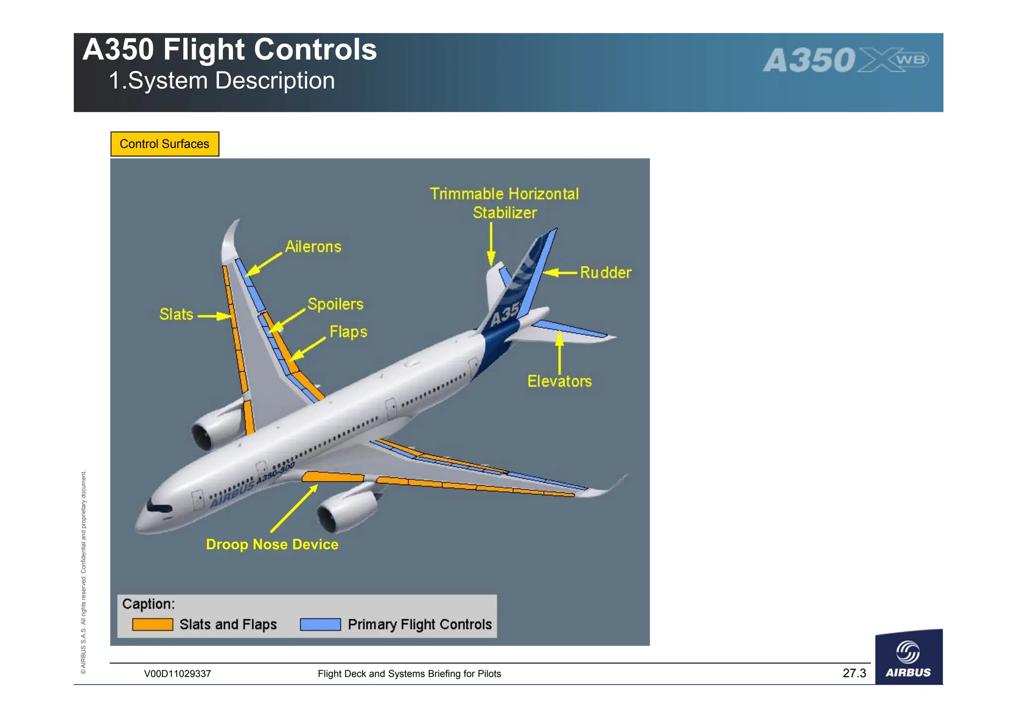
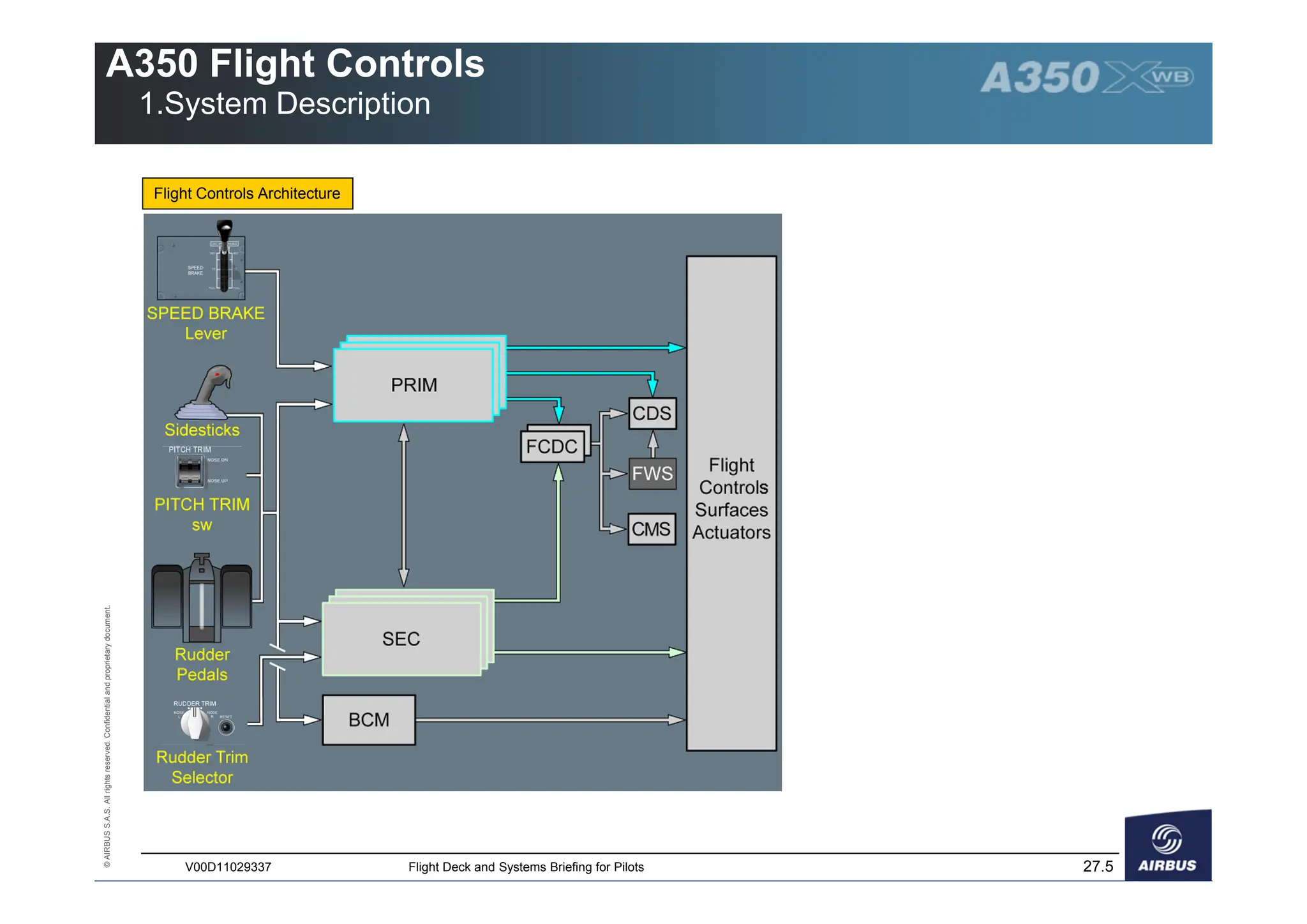
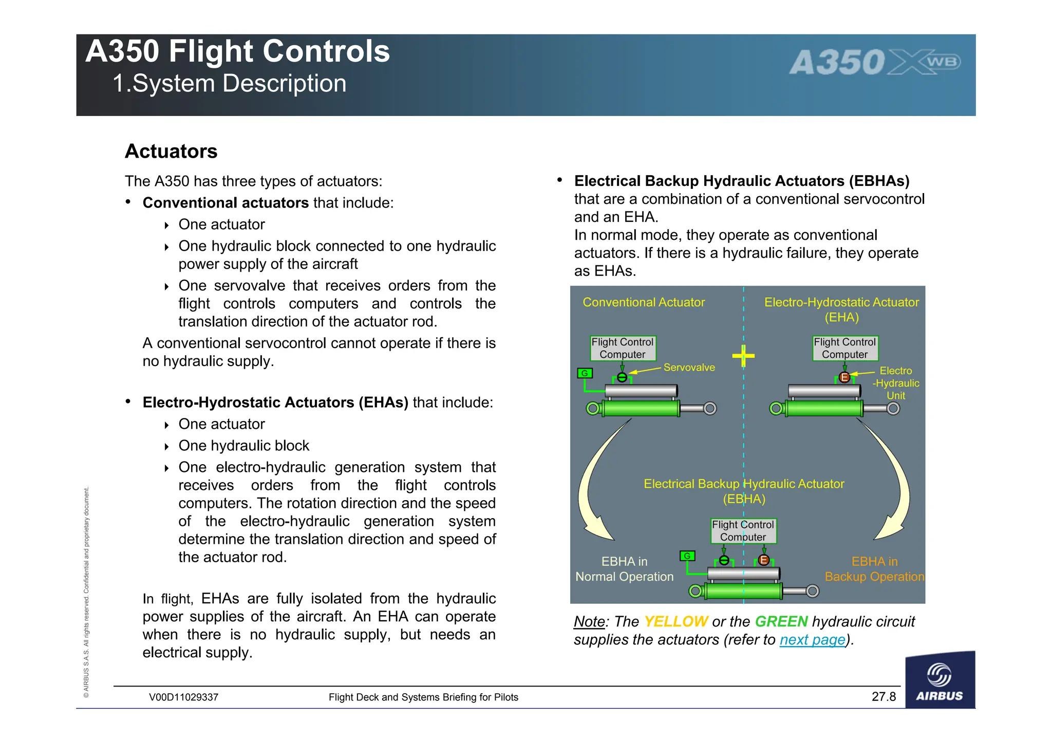
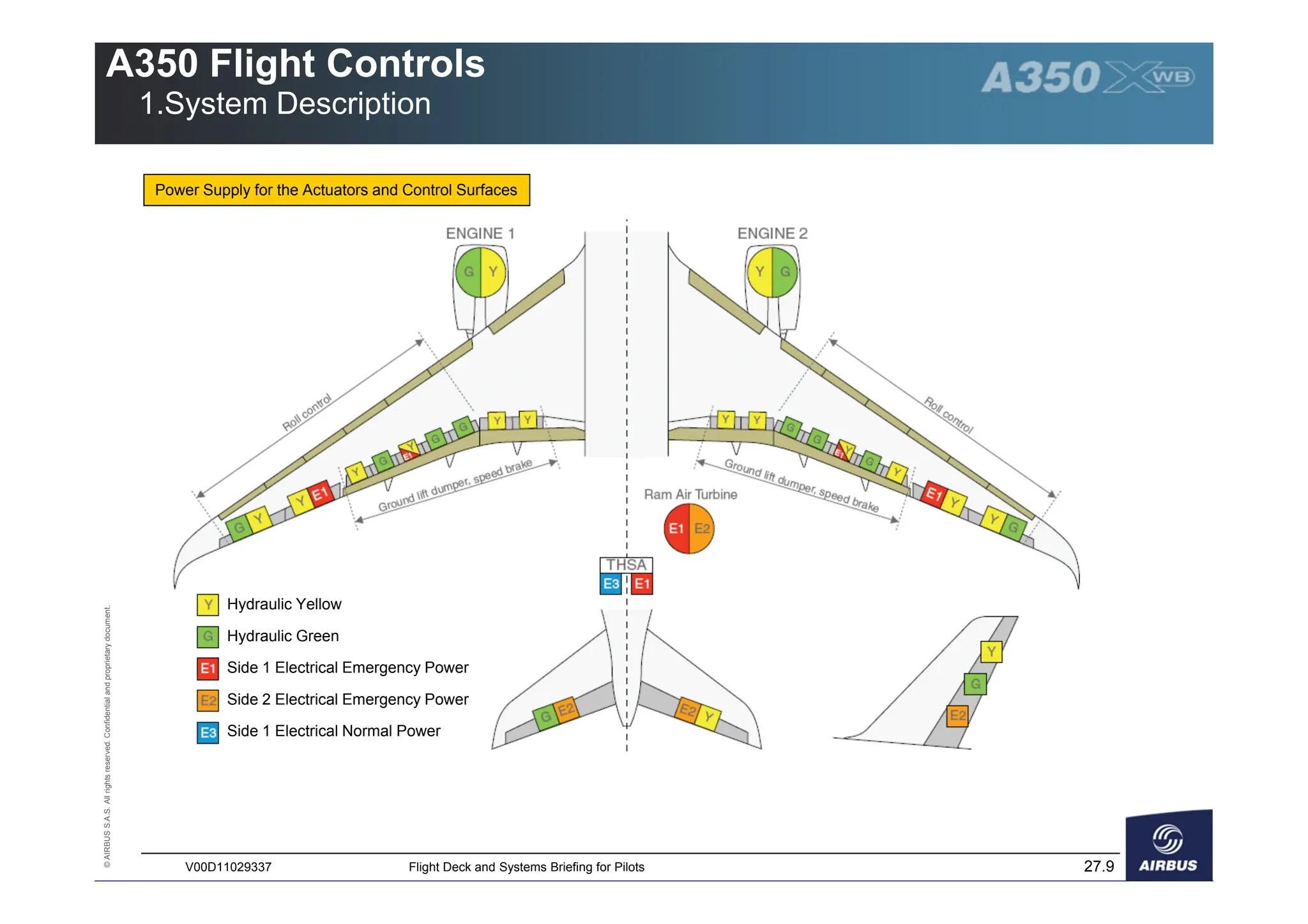
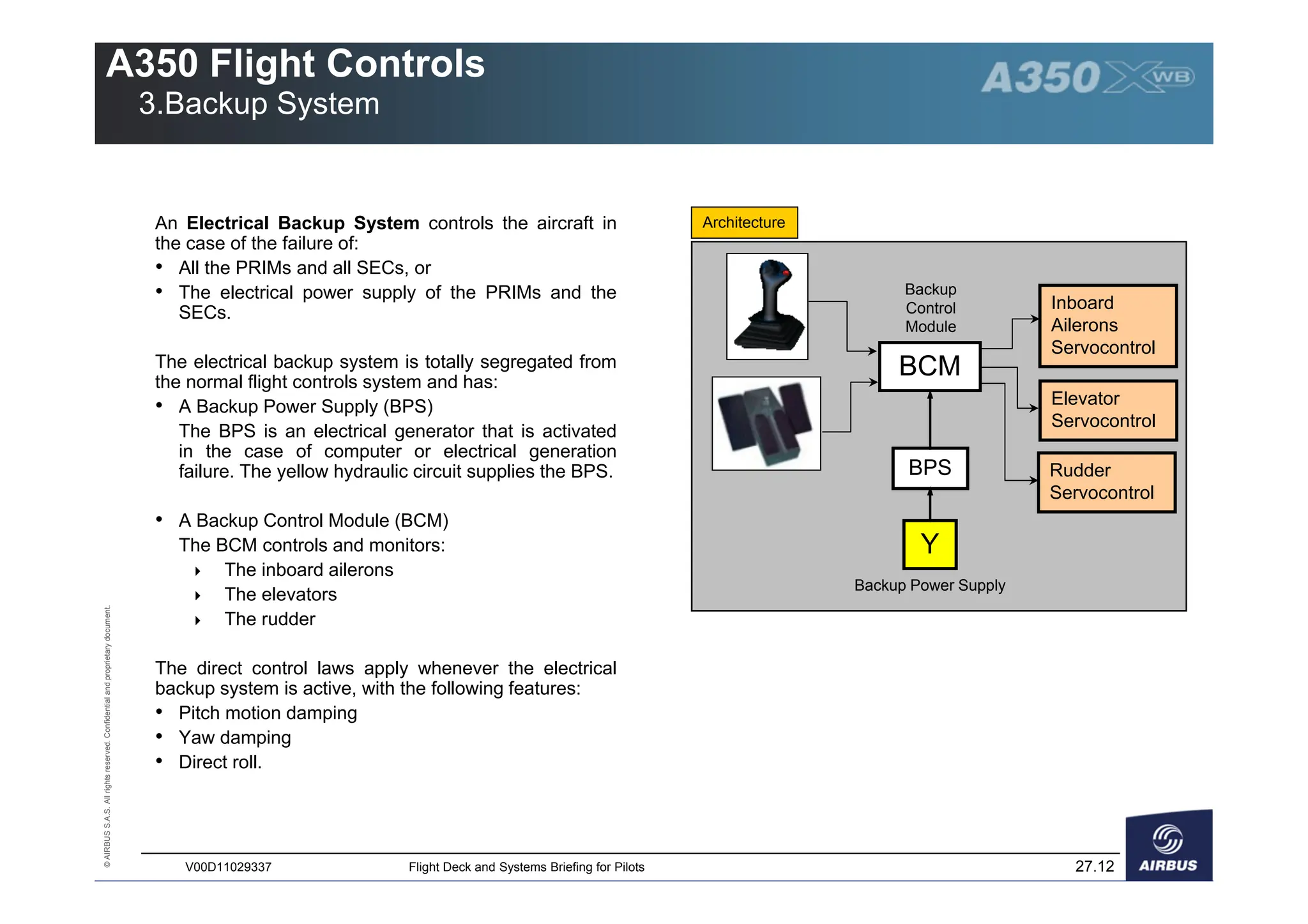
Flight Deck and Systems Briefing for Pilots
1. System Description
- Overview
- Control Surfaces
- System Architecture
- Operations
- Actuators
2. Flight Controls Functions
- Primary Functions
- Auxiliary Functions
3. Backup System
4. Control Laws
- General
- Normal Law
- Engine Failure or Aircraft Asymmetry
- Alternate Law
- Direct Law
5. Controls and Indicators
ATA 27
Flight Controls
©
AIRBUS
S.A.S.
All
rights
reserved.
Confidential
and
proprietary
document.
27.2
V00D11029337 Flight Deck and Systems Briefing for Pilots
A350 Flight Controls
1.System Description
The A350 has fly-by-wire flight controls.
The flight controls can be divided into two categories:
• The primary flight controls which control the
aircraft according to the three axes (Roll, Pitch and
Yaw) and fulfill the auxiliary functions (speedbrakes,
ground spoilers,…)
• The slats and flaps which fulfill the high-lift
function.
The A350 flight controls system benefits from evolutions
introduced on the A380:
• Integration of the Flight Guidance (FG) and Flight
Envelope (FE) functions in the Primary Flight
Computers (PRIMs)
• Replacement of all mechanical backup controls by
electrical backup controls
• Addition of a new pitch trim switch which replaces
the trim wheels
• Introduction of active stability for longitudinal and
lateral axes
• Introduction of Electro-Hydrostatic Actuators (EHAs)
and Electro Backup Hydraulic Actuators (refer to
Actuators).
Overview Control Surfaces
The A350 has:
• 4 ailerons
• 14 spoilers
• 2 elevators and 1 Trimmable Horizontal Stabilizer
(THS)
• 1 rudder
• 12 slats, 4 Adaptive Dropped Hinge Flaps and 2
Droop Nose Devices.
The A350 has two independent hydraulic circuits and
two independent electrical circuits which power the flight
controls surfaces. For more information refer to
Power supply for the Actuators and Control Surfaces
©
AIRBUS
S.A.S.
All
rights
reserved.
Confidential
and
proprietary
document.
27.3
V00D11029337 Flight Deck and Systems Briefing for Pilots
A350 Flight Controls
1.System Description
Control Surfaces
Droop Nose Device
©
AIRBUS
S.A.S.
All
rights
reserved.
Confidential
and
proprietary
document.
27.4
V00D11029337 Flight Deck and Systems Briefing for Pilots
A350 Flight Controls
1.System Description
The flight controls system has:
• Flight deck controls
 Sidesticks
 Rudder pedals
 Rudder trim selector
 Pitch trim switch
 Speed brake lever
The relation between the flight crew input on the
sidestick and the aircraft response is called a Control
Law.
There are three control laws:
 The normal law
 The alternate law
 The direct law.
• Three Primary Flight Computers (PRIMs).
Each PRIM can provide aircraft control under normal,
direct or alternate law. The PRIMs perform the
 Control of flight controls
 Flight Guidance (FG), A/THR and AP/FD
functions
 Flight Envelope (FE) function
• Three Secondary Flight Computers (SECs). The
SECs can provide complete aircraft control in direct
law only.
The computers receive inputs from the pilot controls
or from the Auto Flight System. These inputs are
transformed into control surfaces commands which
are electrically transmitted to actuators.
The A350 has:
• Two Flight Control Data Concentrators (FCDCs)
which acquire data from PRIMs and SECs and send
them to the:
 Control and Display System (CDS)
 Flight Warning System (FWS)
 Centralized Maintenance System (CMS)
• An Electrical Backup System (Backup Control
Module – BCM) that controls the aircraft in the
case of failure of all PRIMs and all SECs (For more
information, refer to Backup System)
• Flight Control Surfaces and Actuators.
System Architecture
©
AIRBUS
S.A.S.
All
rights
reserved.
Confidential
and
proprietary
document.
27.5
V00D11029337 Flight Deck and Systems Briefing for Pilots
A350 Flight Controls
1.System Description
Flight Controls Architecture
©
AIRBUS
S.A.S.
All
rights
reserved.
Confidential
and
proprietary
document.
27.6
V00D11029337 Flight Deck and Systems Briefing for Pilots
A350 Flight Controls
1.System Description
Operations
The PRIMs and SECs compute the flight controls
orders.
Each of these computers can perform two functions:
• The computation function:
 Converts inputs that come from the flight crew
or FG into orders, and computes corresponding
surface deflections that are sent to the other
computers
 Compares the aircraft response with the
objective to check if its orders are fulfilled.
• The execution function:
 Commands the surfaces actuation
 Monitors the surface deflection.
One of the three PRIMs is the master. The master
PRIM computes the flight controls orders and transmits
them to the other computers. Then, each operative
PRIM and SEC activates its respective control surfaces
accordingly.
If a malfunction is detected on the master PRIM, the
master PRIM transfers the computation function to
another PRIM. The master PRIM continues to perform
the execution function, depending on the malfunction.
If all the PRIMs are lost, each SEC performs the
computation and execution functions. There is no
master SEC.
©
AIRBUS
S.A.S.
All
rights
reserved.
Confidential
and
proprietary
document.
27.7
V00D11029337 Flight Deck and Systems Briefing for Pilots
A350 Flight Controls
1.System Description
Intentionally Left Blank
©
AIRBUS
S.A.S.
All
rights
reserved.
Confidential
and
proprietary
document.
27.8
V00D11029337 Flight Deck and Systems Briefing for Pilots
A350 Flight Controls
1.System Description
The A350 has three types of actuators:
• Conventional actuators that include:
 One actuator
 One hydraulic block connected to one hydraulic
power supply of the aircraft
 One servovalve that receives orders from the
flight controls computers and controls the
translation direction of the actuator rod.
A conventional servocontrol cannot operate if there is
no hydraulic supply.
• Electro-Hydrostatic Actuators (EHAs) that include:
 One actuator
 One hydraulic block
 One electro-hydraulic generation system that
receives orders from the flight controls
computers. The rotation direction and the speed
of the electro-hydraulic generation system
determine the translation direction and speed of
the actuator rod.
In flight, EHAs are fully isolated from the hydraulic
power supplies of the aircraft. An EHA can operate
when there is no hydraulic supply, but needs an
electrical supply.
Actuators
• Electrical Backup Hydraulic Actuators (EBHAs)
that are a combination of a conventional servocontrol
and an EHA.
In normal mode, they operate as conventional
actuators. If there is a hydraulic failure, they operate
as EHAs.
Note: The YELLOW or the GREEN hydraulic circuit
supplies the actuators (refer to next page).
©
AIRBUS
S.A.S.
All
rights
reserved.
Confidential
and
proprietary
document.
27.9
V00D11029337 Flight Deck and Systems Briefing for Pilots
A350 Flight Controls
1.System Description
Power Supply for the Actuators and Control Surfaces
Hydraulic Yellow
Hydraulic Green
Side 1 Electrical Emergency Power
Side 2 Electrical Emergency Power
Side 1 Electrical Normal Power
©
AIRBUS
S.A.S.
All
rights
reserved.
Confidential
and
proprietary
document.
27.10
V00D11029337 Flight Deck and Systems Briefing for Pilots
A350 Flight Controls
2.Flight Controls Functions
Primary Functions Auxiliary Functions (1/2)
Lateral Control (Roll+Yaw)
The following surfaces provide lateral control:
• The two pairs of ailerons (Inboard and Outboard)
• Spoilers 3 to 7
• The rudder.
Lateral orders are sent by:
• The sidesticks, to the PRIMs and SECs
• The rudder pedals and pedal feel and trim unit, to the
PRIMs and SECs
• The rudder trim control panel, to the SECs only
• The autopilot, to the PRIMs only.
Pitch Control
The following surfaces provide pitch control:
• The elevators for short-term actions
• The Trimmable Horizontal Stabilizer (THS) for long-
term actions.
Pitch orders are sent by:
• The sidesticks, to the PRIMs and the SECs
• The pitch trim control switches, to the PRIMs and the
SECs (only active on ground or in direct law)
• The autopilot, to the PRIMs only.
Speedbrake Function
The objective of the speedbrake function is to increase
the drag of the aircraft with an acceptable buffet for
passenger comfort.
A speedbrake demand deflects all the spoilers.
The roll command has priority over the speedbrake
command.
An automatic retraction is provided, when one of the
following conditions is fulfilled:
 Angle-of-Attack (AOA) protection is active
 Load factor is lower than 0.3 g in normal or
alternate law
 A go-around is initiated.
Spoilers are lost in symmetrical pairs in the case of a
failure.
Ground Spoilers Function
The objective of the ground spoiler function is to:
 Stick the aircraft to the ground and reduce the
risk of bounce at touchdown
 Increase the efficiency of the brakes
 Decelerate the aircraft.
The ground spoilers function orders the deflection of all
the spoilers.
©
AIRBUS
S.A.S.
All
rights
reserved.
Confidential
and
proprietary
document.
27.11
V00D11029337 Flight Deck and Systems Briefing for Pilots
A350 Flight Controls
2.Flight Controls Functions
Auxiliary Functions (2/2)
Aileron Droop Function
The objective of the aileron droop function is to increase
the high lift function performed by the slats and flaps.
The inboard ailerons droop downwards when the flaps
are extended. They continue to perform the roll
function.
Load Alleviation Function
The objective of the load alleviation function is to reduce
structure fatigue and static loads on the wing during
manoeuvres, turbulence and gust. This function is
available in normal law only.
Differential Flap Setting and Variable Camber
The Differential Flap Setting and Variable Camber enable
to optimize the loads and drag on the wings.
Small flaps deflections (4° maximum) either symmetrically
or asymmetrically, enable to automatically :
 Optimize the wing camber to reduce wing loads
and drag
 Perform an optimized Lateral Trim function.
©
AIRBUS
S.A.S.
All
rights
reserved.
Confidential
and
proprietary
document.
27.12
V00D11029337 Flight Deck and Systems Briefing for Pilots
A350 Flight Controls
3.Backup System
An Electrical Backup System controls the aircraft in
the case of the failure of:
• All the PRIMs and all SECs, or
• The electrical power supply of the PRIMs and the
SECs.
The electrical backup system is totally segregated from
the normal flight controls system and has:
• A Backup Power Supply (BPS)
The BPS is an electrical generator that is activated
in the case of computer or electrical generation
failure. The yellow hydraulic circuit supplies the BPS.
• A Backup Control Module (BCM)
The BCM controls and monitors:
 The inboard ailerons
 The elevators
 The rudder
The direct control laws apply whenever the electrical
backup system is active, with the following features:
• Pitch motion damping
• Yaw damping
• Direct roll.
BCM
Inboard
Ailerons
Servocontrol
Elevator
Servocontrol
Rudder
Servocontrol
Y
BPS
Backup
Control
Module
Backup Power Supply
Architecture

a350-flight-controls systems in pdf format

  • 1.
    Flight Deck andSystems Briefing for Pilots 1. System Description - Overview - Control Surfaces - System Architecture - Operations - Actuators 2. Flight Controls Functions - Primary Functions - Auxiliary Functions 3. Backup System 4. Control Laws - General - Normal Law - Engine Failure or Aircraft Asymmetry - Alternate Law - Direct Law 5. Controls and Indicators ATA 27 Flight Controls
  • 2.
    © AIRBUS S.A.S. All rights reserved. Confidential and proprietary document. 27.2 V00D11029337 Flight Deckand Systems Briefing for Pilots A350 Flight Controls 1.System Description The A350 has fly-by-wire flight controls. The flight controls can be divided into two categories: • The primary flight controls which control the aircraft according to the three axes (Roll, Pitch and Yaw) and fulfill the auxiliary functions (speedbrakes, ground spoilers,…) • The slats and flaps which fulfill the high-lift function. The A350 flight controls system benefits from evolutions introduced on the A380: • Integration of the Flight Guidance (FG) and Flight Envelope (FE) functions in the Primary Flight Computers (PRIMs) • Replacement of all mechanical backup controls by electrical backup controls • Addition of a new pitch trim switch which replaces the trim wheels • Introduction of active stability for longitudinal and lateral axes • Introduction of Electro-Hydrostatic Actuators (EHAs) and Electro Backup Hydraulic Actuators (refer to Actuators). Overview Control Surfaces The A350 has: • 4 ailerons • 14 spoilers • 2 elevators and 1 Trimmable Horizontal Stabilizer (THS) • 1 rudder • 12 slats, 4 Adaptive Dropped Hinge Flaps and 2 Droop Nose Devices. The A350 has two independent hydraulic circuits and two independent electrical circuits which power the flight controls surfaces. For more information refer to Power supply for the Actuators and Control Surfaces
  • 3.
    © AIRBUS S.A.S. All rights reserved. Confidential and proprietary document. 27.3 V00D11029337 Flight Deckand Systems Briefing for Pilots A350 Flight Controls 1.System Description Control Surfaces Droop Nose Device
  • 4.
    © AIRBUS S.A.S. All rights reserved. Confidential and proprietary document. 27.4 V00D11029337 Flight Deckand Systems Briefing for Pilots A350 Flight Controls 1.System Description The flight controls system has: • Flight deck controls Sidesticks Rudder pedals Rudder trim selector Pitch trim switch Speed brake lever The relation between the flight crew input on the sidestick and the aircraft response is called a Control Law. There are three control laws: The normal law The alternate law The direct law. • Three Primary Flight Computers (PRIMs). Each PRIM can provide aircraft control under normal, direct or alternate law. The PRIMs perform the Control of flight controls Flight Guidance (FG), A/THR and AP/FD functions Flight Envelope (FE) function • Three Secondary Flight Computers (SECs). The SECs can provide complete aircraft control in direct law only. The computers receive inputs from the pilot controls or from the Auto Flight System. These inputs are transformed into control surfaces commands which are electrically transmitted to actuators. The A350 has: • Two Flight Control Data Concentrators (FCDCs) which acquire data from PRIMs and SECs and send them to the: Control and Display System (CDS) Flight Warning System (FWS) Centralized Maintenance System (CMS) • An Electrical Backup System (Backup Control Module – BCM) that controls the aircraft in the case of failure of all PRIMs and all SECs (For more information, refer to Backup System) • Flight Control Surfaces and Actuators. System Architecture
  • 5.
    © AIRBUS S.A.S. All rights reserved. Confidential and proprietary document. 27.5 V00D11029337 Flight Deckand Systems Briefing for Pilots A350 Flight Controls 1.System Description Flight Controls Architecture
  • 6.
    © AIRBUS S.A.S. All rights reserved. Confidential and proprietary document. 27.6 V00D11029337 Flight Deckand Systems Briefing for Pilots A350 Flight Controls 1.System Description Operations The PRIMs and SECs compute the flight controls orders. Each of these computers can perform two functions: • The computation function: Converts inputs that come from the flight crew or FG into orders, and computes corresponding surface deflections that are sent to the other computers Compares the aircraft response with the objective to check if its orders are fulfilled. • The execution function: Commands the surfaces actuation Monitors the surface deflection. One of the three PRIMs is the master. The master PRIM computes the flight controls orders and transmits them to the other computers. Then, each operative PRIM and SEC activates its respective control surfaces accordingly. If a malfunction is detected on the master PRIM, the master PRIM transfers the computation function to another PRIM. The master PRIM continues to perform the execution function, depending on the malfunction. If all the PRIMs are lost, each SEC performs the computation and execution functions. There is no master SEC.
  • 7.
    © AIRBUS S.A.S. All rights reserved. Confidential and proprietary document. 27.7 V00D11029337 Flight Deckand Systems Briefing for Pilots A350 Flight Controls 1.System Description Intentionally Left Blank
  • 8.
    © AIRBUS S.A.S. All rights reserved. Confidential and proprietary document. 27.8 V00D11029337 Flight Deckand Systems Briefing for Pilots A350 Flight Controls 1.System Description The A350 has three types of actuators: • Conventional actuators that include: One actuator One hydraulic block connected to one hydraulic power supply of the aircraft One servovalve that receives orders from the flight controls computers and controls the translation direction of the actuator rod. A conventional servocontrol cannot operate if there is no hydraulic supply. • Electro-Hydrostatic Actuators (EHAs) that include: One actuator One hydraulic block One electro-hydraulic generation system that receives orders from the flight controls computers. The rotation direction and the speed of the electro-hydraulic generation system determine the translation direction and speed of the actuator rod. In flight, EHAs are fully isolated from the hydraulic power supplies of the aircraft. An EHA can operate when there is no hydraulic supply, but needs an electrical supply. Actuators • Electrical Backup Hydraulic Actuators (EBHAs) that are a combination of a conventional servocontrol and an EHA. In normal mode, they operate as conventional actuators. If there is a hydraulic failure, they operate as EHAs. Note: The YELLOW or the GREEN hydraulic circuit supplies the actuators (refer to next page).
  • 9.
    © AIRBUS S.A.S. All rights reserved. Confidential and proprietary document. 27.9 V00D11029337 Flight Deckand Systems Briefing for Pilots A350 Flight Controls 1.System Description Power Supply for the Actuators and Control Surfaces Hydraulic Yellow Hydraulic Green Side 1 Electrical Emergency Power Side 2 Electrical Emergency Power Side 1 Electrical Normal Power
  • 10.
    © AIRBUS S.A.S. All rights reserved. Confidential and proprietary document. 27.10 V00D11029337 Flight Deckand Systems Briefing for Pilots A350 Flight Controls 2.Flight Controls Functions Primary Functions Auxiliary Functions (1/2) Lateral Control (Roll+Yaw) The following surfaces provide lateral control: • The two pairs of ailerons (Inboard and Outboard) • Spoilers 3 to 7 • The rudder. Lateral orders are sent by: • The sidesticks, to the PRIMs and SECs • The rudder pedals and pedal feel and trim unit, to the PRIMs and SECs • The rudder trim control panel, to the SECs only • The autopilot, to the PRIMs only. Pitch Control The following surfaces provide pitch control: • The elevators for short-term actions • The Trimmable Horizontal Stabilizer (THS) for long- term actions. Pitch orders are sent by: • The sidesticks, to the PRIMs and the SECs • The pitch trim control switches, to the PRIMs and the SECs (only active on ground or in direct law) • The autopilot, to the PRIMs only. Speedbrake Function The objective of the speedbrake function is to increase the drag of the aircraft with an acceptable buffet for passenger comfort. A speedbrake demand deflects all the spoilers. The roll command has priority over the speedbrake command. An automatic retraction is provided, when one of the following conditions is fulfilled: Angle-of-Attack (AOA) protection is active Load factor is lower than 0.3 g in normal or alternate law A go-around is initiated. Spoilers are lost in symmetrical pairs in the case of a failure. Ground Spoilers Function The objective of the ground spoiler function is to: Stick the aircraft to the ground and reduce the risk of bounce at touchdown Increase the efficiency of the brakes Decelerate the aircraft. The ground spoilers function orders the deflection of all the spoilers.
  • 11.
    © AIRBUS S.A.S. All rights reserved. Confidential and proprietary document. 27.11 V00D11029337 Flight Deckand Systems Briefing for Pilots A350 Flight Controls 2.Flight Controls Functions Auxiliary Functions (2/2) Aileron Droop Function The objective of the aileron droop function is to increase the high lift function performed by the slats and flaps. The inboard ailerons droop downwards when the flaps are extended. They continue to perform the roll function. Load Alleviation Function The objective of the load alleviation function is to reduce structure fatigue and static loads on the wing during manoeuvres, turbulence and gust. This function is available in normal law only. Differential Flap Setting and Variable Camber The Differential Flap Setting and Variable Camber enable to optimize the loads and drag on the wings. Small flaps deflections (4° maximum) either symmetrically or asymmetrically, enable to automatically : Optimize the wing camber to reduce wing loads and drag Perform an optimized Lateral Trim function.
  • 12.
    © AIRBUS S.A.S. All rights reserved. Confidential and proprietary document. 27.12 V00D11029337 Flight Deckand Systems Briefing for Pilots A350 Flight Controls 3.Backup System An Electrical Backup System controls the aircraft in the case of the failure of: • All the PRIMs and all SECs, or • The electrical power supply of the PRIMs and the SECs. The electrical backup system is totally segregated from the normal flight controls system and has: • A Backup Power Supply (BPS) The BPS is an electrical generator that is activated in the case of computer or electrical generation failure. The yellow hydraulic circuit supplies the BPS. • A Backup Control Module (BCM) The BCM controls and monitors: The inboard ailerons The elevators The rudder The direct control laws apply whenever the electrical backup system is active, with the following features: • Pitch motion damping • Yaw damping • Direct roll. BCM Inboard Ailerons Servocontrol Elevator Servocontrol Rudder Servocontrol Y BPS Backup Control Module Backup Power Supply Architecture