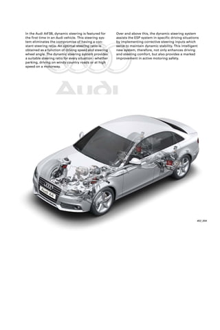
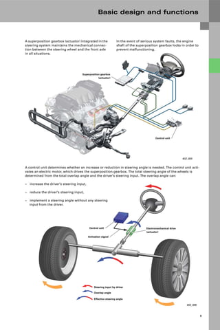
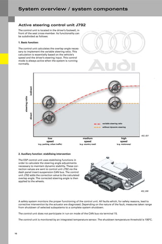
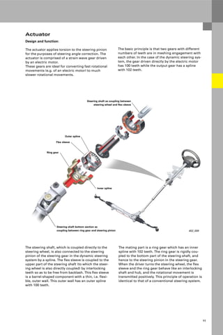
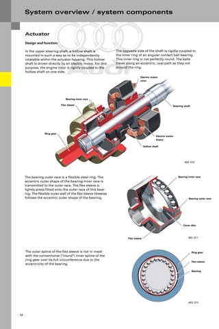
SlideShare a Scribd company logo
1 of 32
Download to read offline
Protected by copyright. Copying for private or commercial purposes, in part or in whole, is not
permitted unless authorised by AUDI AG. AUDI AG does not guarantee or accept any liability
with respect to the correctness of information in this document. Copyright by AUDI AG.
402
All rights reserved. Technical
specifications subject to
change without notice.
Copyright
AUDI AG
I/VK-35
Service.training@audi.de
Fax +49-841/89-36367
AUDI AG
D-85045 Ingolstadt
Technical status: 08/07
Printed in Germany
A07.5S00.39.20
Dynamic Steering in the Audi A4’08
Self-Study Programme 402
Vorsprung durch Technik www.audi.de Service Training
Protected by copyright. Copying for private or commercial purposes, in part or in whole, is not
permitted unless authorised by AUDI AG. AUDI AG does not guarantee or accept any liability
with respect to the correctness of information in this document. Copyright by AUDI AG.
402_004
Over and above this, the dynamic steering system
assists the ESP system in specific driving situations
by implementing corrective steering inputs which
serve to maintain dynamic stability. This intelligent
new system, therefore, not only enhances driving
and steering comfort, but also provides a marked
improvement in active motoring safety.
In the Audi A4’08, dynamic steering is featured for
the first time in an Audi vehicle. This steering sys-
tem eliminates the compromise of having a con-
stant steering ratio. An optimal steering ratio is
obtained as a function of driving speed and steering
wheel angle. The dynamic steering system provides
a suitable steering ratio for every situation - whether
parking, driving on windy country roads or at high
speed on a motorway.
Protected by copyright. Copying for private or commercial purposes, in part or in whole, is not
permitted unless authorised by AUDI AG. AUDI AG does not guarantee or accept any liability
with respect to the correctness of information in this document. Copyright by AUDI AG.
Note
Reference
The self-study programme teaches the design and function of new vehicle models,
new automotive parts or new technologies.
The self-study programme is not a repair manual!
All values given are intended as a guideline only and refer to the software version valid at the time of prepara-
tion of the SSP.
For maintenance and repair work, always refer to the current technical literature.
Contents
Basic design and functions
System overview / system components
Active steering control unit J792 . . . . . . . . . . . . . . . . . . . . . . . . . . . . . . . . . . . . . . . 10
Actuator . . . . . . . . . . . . . . . . . . . . . . . . . . . . . . . . . . . . . . . . . . . . . . . . . . . . . . . . . . . . . 11
Electric motor . . . . . . . . . . . . . . . . . . . . . . . . . . . . . . . . . . . . . . . . . . . . . . . . . . . . . . . . 14
Dynamic steering lock. . . . . . . . . . . . . . . . . . . . . . . . . . . . . . . . . . . . . . . . . . . . . . . . . 15
Sensors . . . . . . . . . . . . . . . . . . . . . . . . . . . . . . . . . . . . . . . . . . . . . . . . . . . . . . . . . . . . . 16
System overview . . . . . . . . . . . . . . . . . . . . . . . . . . . . . . . . . . . . . . . . . . . . . . . . . . . . . 18
Function diagram / CAN data interchange
Introduction
Operation and driver information
Special system functions
Steering ratio selection. . . . . . . . . . . . . . . . . . . . . . . . . . . . . . . . . . . . . . . . . . . . . . . . 22
Functions of the ESP button E256 . . . . . . . . . . . . . . . . . . . . . . . . . . . . . . . . . . . . . . 22
Function and fault indication . . . . . . . . . . . . . . . . . . . . . . . . . . . . . . . . . . . . . . . . . . 23
Steering pump with ECO function
Initialisation. . . . . . . . . . . . . . . . . . . . . . . . . . . . . . . . . . . . . . . . . . . . . . . . . . . . . . . . . . 24
Initialisation after a fault. . . . . . . . . . . . . . . . . . . . . . . . . . . . . . . . . . . . . . . . . . . . . . . 25
Overview . . . . . . . . . . . . . . . . . . . . . . . . . . . . . . . . . . . . . . . . . . . . . . . . . . . . . . . . . . . . 28
Design and function . . . . . . . . . . . . . . . . . . . . . . . . . . . . . . . . . . . . . . . . . . . . . . . . . . 29
System response in the event of a fault . . . . . . . . . . . . . . . . . . . . . . . . . . . . . . . . . 30
Servicing
Protected by copyright. Copying for private or commercial purposes, in part or in whole, is not
permitted unless authorised by AUDI AG. AUDI AG does not guarantee or accept any liability
with respect to the correctness of information in this document. Copyright by AUDI AG.
4
Introduction
Nevertheless, only one ratio can be implemented in
a vehicle at a time. The selection of suitable ratios
always represents a best possible compromise
between different and at times conflicting require-
ments. The ratio characteristic curve of the conven-
tional power steering system of the Audi A4 without
dynamic steering is shown in yellow in the diagram.
402_001
low
speed
(e.g. parking, urban traffic)
medium
speed
(e.g. country road)
high
speed
(e.g. motorway)
steering
ratio
indirect
direct
Dynamic set-up
Comfort set-up
without dynamic steering
In conventional steering systems there is a direct
mechanical connection between the steering wheel
and the steering gear. This also means there is a
given relationship between the steering wheel angle
and the lock angle of the steered wheels. The geo-
metric configuration of the interlocking teeth of the
steering gear rack and the steering pinion rack
allows different ratios to be obtained.
For the Audi A4, the dynamic steering system gener-
ally implements two variable curves with comforta-
ble and sporty characteristics (red characteristic
curves in the diagram). Drivers can select the char-
acteristic curve which suits their preferences (refer
to chapter "Operation and driver information"). The
dependency of steering ratio on vehicle speed is
clearly recognisable.
The key requirements can only be met optimally by
a variable ratio characteristic curve. Such a charac-
teristic curve varies the actual steering angle of the
wheels according to driving speed and steering
angle.
Protected by copyright. Copying for private or commercial purposes, in part or in whole, is not
permitted unless authorised by AUDI AG. AUDI AG does not guarantee or accept any liability
with respect to the correctness of information in this document. Copyright by AUDI AG.
5
The variable characteristic curve is implemented by
an additional electromechanical drive steering pin-
ion, which is superimposed on the driver's steering
input.
402_002
Steering gear
Steering pinion
Electronic control unit
Electromechanical drive
Activation signal
In an emergency, i.e. in case of failure of this drive,
the steering system functions in exactly the same
way as a conventional steering system.
Secondly, in less critical driving situations braking
can be dispensed with either partially or even com-
pletely, thereby allowing the vehicle to be stabilised
more harmoniously and comfortably. By reducing
the number of corrective braking inputs, particularly
on road surfaces with a low friction coefficient (e.g.
snow-covered roads), the vehicle moves with much
greater agility than a vehicle stabilised by braking
only while achieving the same level of driving stabil-
ity.
ESP utilises the dynamic steering function in both
oversteer and understeer situations, as well as
under braking on road surfaces with different fric-
tion coefficients (μ-split).
However, the advantages of the dynamic steering
system go far beyond that. Working in conjunction
with the ESP system and associated sensors, the
system also activates when critical driving situa-
tions are imminent.
The dynamic steering system assists the ESP at the
dynamic stability limit through controlled adjust-
ment of the front-wheel steering angle.
This has two key advantages. Firstly, the overall sta-
bility of the vehicle is improved through simultane-
ous corrective braking and steering inputs, i.e.
active safety is significantly enhanced. This is espe-
cially true at high speeds (>100 kph), since at these
speeds the dynamic steering system can take full
advantage of its very quick reaction times.
Protected by copyright. Copying for private or commercial purposes, in part or in whole, is
permitted unless authorised by AUDI AG. AUDI AG does not guarantee or accept any liab
with respect to the correctness of information in this document. Copyright by AUDI AG.
6
Introduction
402_044
Wheel steering angle
Steering wheel angle
Stabilisation angle
Brake pressure, front left
Brake pressure, front right
Brake
pressure
Steering
angle
Time
When steering back on the new lane, particularly at
high speeds, the rear end may begin to slide side-
ways (fishtail). The driver is often too late applying
the necessary counter-steer, or fail to do so at all.
Heavy corrective braking by the ESP system is the
consequence.
402_045
Brake
pressure
Steering
angle
Time
Wheel steering angle
Steering wheel angle
Stabilisation angle
Brake pressure, front left
Brake pressure, front right
Stabilising counter-steer by
dynamic steering system
With the dynamic steering system, stabilising coun-
ter-steer is applied automatically, without the driver
noticing anything. This significantly reduces the
steering effort required on the part of the driver.
The driver need only apply the steering angle that
would be necessary in a similar, stable driving situa-
tion.
There is also much less need for corrective braking
by the ESP system.
This translates to improved vehicle stability when
changing lanes and higher lane-changing speeds.
Oversteering vehicle
In an oversteer situation, ESP stabilises the vehicle
by integrating the dynamic steering system, which
applies a controlled amount of counter-steer in
order to prevent the rear end of the vehicle from
"fishtailing".
A typical situation which can easily cause the vehicle
to oversteer is changing lanes quickly.
Protected by copyright. Copying for private or commercial purposes, in part or in whole, is not
permitted unless authorised by AUDI AG. AUDI AG does not guarantee or accept any liability
with respect to the correctness of information in this document. Copyright by AUDI AG.
7
402_003
Lateral
force
Slip angle
Vehicle 2
Vehicle 1
Increase in lateral force due to
understeer stabilisation angle of
dynamic steering system
Understeering vehicle
In an understeer situation, the vehicle veers towards
the outside of the road when the front wheels are
turned.
This driving state is characterised by decreasing lat-
eral traction with increasing steering angle, with the
result that the cornering radius becomes larger.
Lateral traction is thereby preserved, and the vehicle
travels along the shortest physically possible curve
radius.
If this is insufficient, the ESP system applies correc-
tive braking preferably to the wheels on the inside
of the curve. Additional stabilising counter-torque is
thereby produced about the vehicle's vertical axis.
The vehicle is thus braked and steered back onto the
desired trajectory.
Most drivers react to this situation by applying more
steering lock (vehicle 1). That has the effect of
reducing the available lateral traction, with the
result that the static friction between the tyres and
the road surface becomes sliding friction, causing
the vehicle to lose control and leave the road. In this
situation, corrective intervention by the ESP system
will often be of no use.
The dynamic steering system takes corrective action
before this happens. The dynamic steering system
"countersteers" the vehicle (vehicle 2). The actual
angle which the wheels turn is less than the angle
set by the driver via the steering wheel.
Protected by copyright. Copying for private or commercial purposes, in part or in whole, is not
permitted unless authorised by AUDI AG. AUDI AG does not guarantee or accept any liability
with respect to the correctness of information in this document. Copyright by AUDI AG.
8
So-called μ-split surfaces are characterised in that
the road surface has a high friction coefficient on
one side of the vehicle (e.g. dry tarmac) and a low
friction coefficient on the other side (e.g. water or
ice). This is the case for example when snow-cov-
ered or icy road surfaces are partially thawed or
when wet leaves is lying on an otherwise dry road.
Under braking, the vehicle "pulls" towards the side
of the road with the higher friction coefficient where
braking force is stronger.
To be able to maintain a straight line in a vehicle
without dynamic steering, the driver must apply
enough steering lock to compensate for the pull
effect. In a vehicle with dynamic steering, the steer-
ing angle is automatically controlled by the ESP and
dynamic steering systems. The driver does not
notice anything and the steering wheel remains in
the position corresponding to the desired direction
of travel. Since ESP and dynamic steering are able
to set the required steering angle more quickly and
accurately than the driver, the additional use of
dynamic steering in this driving situation provides,
on average, shorter stopping distances than in vehi-
cles without dynamic steering .
402_046
Wheel steering angle
Steering wheel angle
Stabilisation angle
Brake pressure, front left/rear left
Brake pressure, front right/rear right
Brake
pressure
Steering
angle
Time
Braking on road surfaces with different friction coefficients (μ-split)
Protected by copyright. Copying for private or commercial purposes, in part or in whole, is not
permitted unless authorised by AUDI AG. AUDI AG does not guarantee or accept any liability
with respect to the correctness of information in this document. Copyright by AUDI AG.
9
Basic design and functions
402_005
Superposition gearbox
(actuator)
Control unit
402_006
Steering input by driver
Overlap angle
Effective steering angle
Control unit Electromechanical drive
(actuator)
Activation signal
A superposition gearbox (actuator) integrated in the
steering system maintains the mechanical connec-
tion between the steering wheel and the front axle
in all situations.
In the event of serious system faults, the engine
shaft of the superposition gearbox locks in order to
prevent malfunctioning.
A control unit determines whether an increase or reduction in steering angle is needed. The control unit acti-
vates an electric motor, which drives the superposition gearbox. The total steering angle of the wheels is
determined from the total overlap angle and the driver's steering input. The overlap angle can:
– increase the driver's steering input,
– reduce the driver's steering input,
– implement a steering angle without any steering
input from the driver.
Protected by copyright. Copying for private or commercial purposes, in part or in whole, is not
permitted unless authorised by AUDI AG. AUDI AG does not guarantee or accept any liability
with respect to the correctness of information in this document. Copyright by AUDI AG.
10
System overview / system components
402_007
low
speed
(e.g. parking, urban traffic)
medium
speed
(e.g. country road)
high
speed
(e.g. motorway)
steering
ratio
indirect
direct
variable steering ratio
without dynamic steering
402_008
2. Auxiliary function: stabilising intervention
The ESP control unit uses stabilising functions in
order to calculate the steering angle adjustments
necessary to maintain dynamic stability. These cor-
rection values are sent to control unit J792 via the
dash panel insert-suspension CAN bus. The control
unit J792 adds the correction value to the calculated
overlap angle. The corrected steering angle is then
applied to the wheels.
The control unit is located in the driver's footwell, in
front of the seat cross-member. Its functionality can
be subdivided as follows:
1. Basic function:
The control unit calculates the overlap angle neces-
sary to implement the variable steering ratio. This
calculation is essentially based on the vehicle's
speed and the driver's steering input. This control
mode is always active when the system is running
normally.
Active steering control unit J792
A safety system monitors the proper functioning of the control unit. All faults which, for safety reasons, lead to
corrective intervention by the actuator are diagnosed. Depending on the nature of the fault, measures taken range
from shutdown of selected subsystems to a complete system shutdown.
The control unit does not participate in run-on mode of the CAN bus via terminal 15.
The control unit is monitored by an integrated temperature sensor. The shutdown temperature threshold is 100°C.
Protected by copyright. Copying for private or commercial purposes, in part or in whole, is not
permitted unless authorised by AUDI AG. AUDI AG does not guarantee or accept any liability
with respect to the correctness of information in this document. Copyright by AUDI AG.
11
402_009
Flex sleeve
Steering shaft as coupling between
steering wheel and flex sleeve
Ring gear
Steering shaft bottom section as
coupling between ring gear and steering pinion
Outer spline
Inner spline
Actuator
The basic principle is that two gears with different
numbers of teeth are in meshing engagement with
each other. In the case of the dynamic steering sys-
tem, the gear driven directly by the electric motor
has 100 teeth while the output gear has a spline
with 102 teeth.
The steering shaft, which is coupled directly to the
steering wheel, is also connected to the steering
pinion of the steering gear in the dynamic steering
system by a spline. The flex sleeve is coupled to the
upper part of the steering shaft (to which the steer-
ing wheel is also directly coupled) by interlocking
teeth so as to be free from backlash. This flex sleeve
is a barrel-shaped component with a thin, i.e. flexi-
ble, outer wall. This outer wall has an outer spline
with 100 teeth.
The mating part is a ring gear which has an inner
spline with 102 teeth. The ring gear is rigidly cou-
pled to the bottom part of the steering shaft, and
hence to the steering pinion in the steering gear.
When the driver turns the steering wheel, the flex
sleeve and the ring gear behave like an interlocking
shaft and hub, and the rotational movement is
transmitted positively. This principle of operation is
identical to that of a conventional steering system.
Design and function:
The actuator applies torsion to the steering pinion
for the purposes of steering angle correction. The
actuator is comprised of a strain wave gear driven
by an electric motor.
These gears are ideal for converting fast rotational
movements (e.g. of an electric motor) to much
slower rotational movements.
Protected by copyright. Copying for private or commercial purposes, in part or in whole, is not
permitted unless authorised by AUDI AG. AUDI AG does not guarantee or accept any liability
with respect to the correctness of information in this document. Copyright by AUDI AG.
12
System overview / system components
The opposite side of the shaft is rigidly coupled to
the inner ring of an angular contact ball bearing.
This inner ring is not perfectly round. The balls
travel along an eccentric, oval path as they roll
around the ring.
402_010
Bearing inner race
Electric motor
rotor
Steering shaft
Electric motor
Stator
Hollow shaft
Flex sleeve
Ring gear
402_011
Bearing inner race
Bearing outer race
Flex sleeve
Cover disc
The bearing outer race is a flexible steel ring. The
eccentric outer shape of the bearing inner race is
transmitted to the outer race. The flex sleeve is
lightly press fitted onto the outer race of this bear-
ing. The flexible outer wall of the flex sleeve likewise
follows the eccentric outer shape of the bearing.
The outer spline of the flex sleeve is not in mesh
with the conventional ("round") inner spline of the
ring gear over its full circumference due to the
eccentricity of the bearing.
402_012
Ring gear
Flex sleeve
Bearing
Actuator
Design and function:
In the upper steering shaft, a hollow shaft is
mounted in such a way as to be independently
rotatable within the actuator housing. This hollow
shaft is driven directly by an electric motor. For this
purpose, the engine rotor is rigidly coupled to the
hollow shaft on one side.
Protected by copyright. Copying for private or commercial purposes, in part or in whole, is not
permitted unless authorised by AUDI AG. AUDI AG does not guarantee or accept any liability
with respect to the correctness of information in this document. Copyright by AUDI AG.
13
402_013
Eccentricity
When the electric motor is actuated, the hollow
shaft is driven. The inner ring of the angular contact
ball bearings rotates, causing the eccentricity to
rotate as well. Due to the different numbers of teeth
on the flex sleeve spline and on the ring gear spline,
the teeth on the flex sleeve do not mesh exactly
with the teeth on the ring gear. The teeth on the flex
sleeve engage the tooth flanks of the ring gear in a
laterally offset manner.
The resultant force acting on this tooth flank pro-
duces a minimal rotational movement of the ring
gear. All the teeth on the circumference of the
spline mesh in a time-shifted manner due to the
"rotation" of the eccentricity under motor drive. This
produces a continuous rotational movement of the
ring gear and the steering pinion coupled to it. The
steering angle of the wheels changes. The reduction
ratio from the motor to the steering pinion is
approximately 50:1.
402_014
L = 0°
H = +0°
L = 90°
H = +0.88°
L = 180°
H = +1.76°
L = 270°
H = +2.65°
L = 360°
H = +3.53°
Inner bearing ring (L)
Ring gear (H)
Protected by copyright. Copying for private or commercial purposes, in part or in whole, is not
permitted unless authorised by AUDI AG. AUDI AG does not guarantee or accept any liability
with respect to the correctness of information in this document. Copyright by AUDI AG.
14
System overview / system components
402_017
Hollow shaft
Rotor
The motor is activated by three phase-offset AC volt-
ages, which produce a rotating magnetic field
around the stationary coils. The force action of this
alternating magnetic field on the permanent mag-
net of the rotor mounted on the hollow shaft
induces a rotational movement of the rotor.
The principal advantage of this type of electric
motor is that it has a quick response, which is essen-
tial for making corrective steering inputs to stabilise
the vehicle.
The stator consists of six pairs of coils. The coils are
arranged inside the actuator housing and activated
by the control unit. The shielded supply lead is con-
nected to the actuator housing.
Electric motor
A permanently excited synchronous motor is
deployed. The rotor rigidly coupled to the hollow
shaft is comprised of eight permanent magnets
with alternating polarity.
402_018
Stator
Protected by copyright. Copying for private or commercial purposes, in part or in whole, is not
permitted unless authorised by AUDI AG. AUDI AG does not guarantee or accept any liability
with respect to the correctness of information in this document. Copyright by AUDI AG.
15
402_019
Locking ring
Plunger
Hollow shaft
Shift lock solenoid
402_020
Magnetic coil
Plunger Locking ring
Compression
spring
FF = spring force
Dynamic steering lock
To represent a safe fallback mode in the event of a
system fault or failure, the dynamic steering gear
can be locked (disabled) mechanically. During nor-
mal operation, the lock is engaged whenever the
internal combustion engine is shut off.
402_021
FM = magnetic force
A ring with multiple outer recesses is attached to
the electric motor driven hollow shaft. The cylindri-
cal plunger of the solenoid engages these recesses.
The hollow shaft is thereby locked, and the eccen-
tric bearing can no longer be driven by the electric
motor.
The plunger locks the dynamic steering gear with-
out electrical current, and is held in its limit stop
position by a compression spring.
If the magnetic coil is activated via the discrete from
control unit J792, the plunger is moved towards the
magnetic coil against the pressure of the spring.
The plunger is thereby disengaged releasing the
hollow shaft and the dynamic steering gear.
When the engine is started, the dynamic steering
system is unlocked, as indicated by an audible
"click" noise.
Locking is provided by a solenoid bolted onto the
gearbox housing.
Protected by copyright. Copying for private or commercial purposes, in part or in whole, is not
permitted unless authorised by AUDI AG. AUDI AG does not guarantee or accept any liability
with respect to the correctness of information in this document. Copyright by AUDI AG.
16
System overview / system components
Sensors
Motor position sensor
The position of the hollow shaft, i.e. the eccentricity
of the bearing, is measured by a motor position
sensor. A magnetic ring on the hollow shaft acts as
a sender. The magnetic ring is comprised of eight
poles. The magnetic field is measured by a sensor
with three Hall elements. A signal is generated for
every 15-degree revolution of the motor (equivalent
to 0.3 degrees at the steering wheel) and sent
through discrete wiring to control unit J792. The
actual position is stored in control unit J792 when
the ignition is turned off. In the event of a sudden
loss of terminal 30, the zero position is identified by
the index sensor (refer to "Initialisation" on page
24).
402_022
402_023
The motor position sensor and index sensor
are installed in a common housing.
402_024
Index sensor recess
Index sensor
The index sensor outputs one signal per turn of the
steering wheel or per revolution of the actuator out-
put shaft. This signal is used to determine the cen-
tre position of the steering gear and for initialising
the control unit after a fault (refer to "Initialisation
after a fault"). A magnetically preloaded Hall sensor
is used. The sensor is installed together with the
motor position sensor in a common housing. A
recess on the outside of the output-end ring gear
serves as a sender. This recess produces a square-
wave signal at the Hall sensor of the index sensor.
Protected by copyright. Copying for private or commercial purposes, in part or in whole, is not
permitted unless authorised by AUDI AG. AUDI AG does not guarantee or accept any liability
with respect to the correctness of information in this document. Copyright by AUDI AG.
17
Two sensor units (G419 and G536) are used on vehi-
cles with dynamic steering. The sensor units are
functionally identical and, when intact, deliver iden-
tical signals for yaw rate and transverse accelera-
tion. The sensor units can be distinguished
externally by their connectors.
The dual-sensor configuration provides security
against malfunctions, which can be caused by faulty
sensor signals. The signals from both sensors are
checked to ensure they have the same wave form.
402_025
402_026
Steering angle sender G85
A key input signal is that of momentary steering
angle. This signal is required both for calculating
the overlap angle required to obtain the variable
steering ratio and for calculating the overlap angle
necessary to stabilise the vehicle.
For this reason, the information is read in by both
control units (J104 and J792).
The steering angle sender is configured for redun-
dancy.
It outputs prepared measured data to the dash
panel insert-suspension CAN bus.
The sensor units are connected to the ESP control
unit J104 and the active steering control unit J792
by sensor-CAN. The ESP control unit requires the
signals of both sensor units in order to calculate the
steering overlap angle necessary to stabilise the
vehicle.
The sensor units are located below the driver seat.
ESP sensor unit G419 and ESP sensor unit 2 G536
Protected by copyright. Copying for private or commercial purposes, in part or in whole, is not
permitted unless authorised by AUDI AG. AUDI AG does not guarantee or accept any liability
with respect to the correctness of information in this document. Copyright by AUDI AG.
18
Actuator
Dynamic steering
Steering angle sender G85
Control unit
ABS/ESP J104
System overview / system components
System overview
Protected by copyright. Copying for private or commercial purposes, in part or in whole, is not
permitted unless authorised by AUDI AG. AUDI AG does not guarantee or accept any liability
with respect to the correctness of information in this document. Copyright by AUDI AG.
19
402_026a
ESP sensor unit G419
ESP sensor unit 2 G536
Index sensor
Motor position sensor
Dynamic steering lock
Active steering control
unit J792
Protected by copyright. Copying for private or commercial purposes, in part or in whole, is not
permitted unless authorised by AUDI AG. AUDI AG does not guarantee or accept any liability
with respect to the correctness of information in this document. Copyright by AUDI AG.
20
Function diagram / CAN data interchange
Function diagram
402_030
Steering pump ECO
valve
Electric motor Index sensor Motor
position sensor
Lock
J792 Active steering control unit
Positive
Ground
Output signal
Input signal
Dash panel insert - suspension CAN
Sensor-CAN to ESP control unit J104
Protected by copyright. Copying for private or commercial purposes, in part or in whole, is not
permitted unless authorised by AUDI AG. AUDI AG does not guarantee or accept any liability
with respect to the correctness of information in this document. Copyright by AUDI AG.
21
CAN data interchange
J792 Active steering control unit
System status (4,9)
Total overlap angle (4)
Direction of total overlap angle (4)
Dynamic reserve* (4)
Warning lamp activation (6)
Warnings (6)
Current driving program (9)
Changeover request recognition (9)
J533 Data bus diagnostic interface (1)
Time
Date
Mileage (km)
J220 Motronic control unit (2)
System status
Normal operation
Engine speed
J393 Central convenience electronics con-
trol unit (3)
Vehicle identification number
*: indicates, in degrees, the steering angle and speed which can be set by activating the electric motor;
J104 ESP control unit (4)
System status
Direction of travel
Road speed
Wheels speeds
Steering angle request
G85 Steering angle sender (5)
Steering angle
Turning direction
Steering angle speed
J285 Control unit with display in dash
panel insert (6)
Receiver only
G419 ESP sensor unit (7)
System status
Lateral acceleration
Yaw rate
G536 ESP sensor unit 2 (8)
System status
Lateral acceleration
Yaw rate
J519 Onboard power supply control
unit (9)
Status of Audi drive select system
Driving program request from Audi
drive select
Information sent by control unit J792 The number in brackets
denotes the bus users to which the information is sent
Information received and evaluated
by control unit J792
Powertrain CAN bus
Dash panel insert-suspension CAN
Convenience CAN
Sensor-CAN
402_031
Protected by copyright. Copying for private or commercial purposes, in part or in whole, is not
permitted unless authorised by AUDI AG. AUDI AG does not guarantee or accept any liability
with respect to the correctness of information in this document. Copyright by AUDI AG.
22
Operation and driver information
Functions of the ESP button E256
Pressing the button for longer than 3 s deactivates
the ESP function.
The stabilising functions of the dynamic steering
system are also deactivated in understeer and overs-
teer situations.
However, the stabilising function of the dynamic
steering system continues to be fully available under
braking on
road surfaces with different friction coefficients.
This function cannot be deactivated by the driver.
402_027
Switch position in vehicles with MMI
402_028
Switch position in vehicles without MMI
Briefly pressing the button (<3 s) deactivates the
TCS function.
However, the stabilising function of the dynamic
steering system continues to be fully available.
The ESP function remains active, but the braking is
reduced.
This mode is designed specifically for "freeing" the
vehicle when it is stuck in loose surfaces or snow,
for example.
Pressing the button for longer than 10 s reactivates
all functions. The ESP function cannot be deacti-
vated again until the ignition is turned off and back
on.
Steering ratio selection
With Audi drive select, drivers can select a steering
ratio to suit their preferences (Dynamic or Comfort).
For detailed information regarding Audi drive
select, please refer to Self-Study Programme 409.
Protected by copyright. Copying for private or commercial purposes, in part or in whole, is not
permitted unless authorised by AUDI AG. AUDI AG does not guarantee or accept any liability
with respect to the correctness of information in this document. Copyright by AUDI AG.
23
If a system fault occurs, this is indicated on the cen-
tre display of the dash panel insert and by the warn-
ing lamp.
System response varies according to fault severity.
The control unit is designed in such a way that the
system can continue to operate with a minimum of
limitations.
Each possible and diagnosable fault is assigned to
an explicitly defined system limitation (="fallback
mode").
The following deviations in system response can
occur:
– The vehicle's steering response has been modi-
fied. When driving at low speeds, more steering
input may be necessary. At high speeds, the
vehicle may respond more sensitively to steering
inputs.
– The stabilising functions of the dynamic steering
system are no longer are available.
– The steering wheel may be at an angle when driv-
ing in a straight line.
In the event of serious system faults, all functions of
the dynamic steering system are disabled.
402_034
Dynamic steering:
system fault
8224 km
+ 13.5°c
91.7
A warning lamp integrated in the rev counter serves
the dynamic steering system as a function and fault
indicator.
Texts are also shown on the centre display.
The diagnostic warning lamp is checked when the
ignition is turned on. The warning lamp remains
activated until the engine is started. When the
engine is running, the dynamic steering system is
activated by releasing the lock.
Function and fault indication
402_029
Protected by copyright. Copying for private or commercial purposes, in part or in whole, is not
permitted unless authorised by AUDI AG. AUDI AG does not guarantee or accept any liability
with respect to the correctness of information in this document. Copyright by AUDI AG.
24
Note
The steering wheel may move without any
action by the driver during the stationary initial-
isation routine.
On account of current statutory requirements, the
dynamic steering system is designed in such a way
that, despite the possibility for electromechanical
adjustment, a permanent mechanical connection
exists between the steering wheel and the steering
pinion. Even when dynamic steering is off, it is pos-
sible to steer the wheels with the steering wheel
(e.g. to carry out repairs with the vehicle raised on
the lift). Such a steering operation is executed with-
out steering angle overlap by the dynamic steering
system, i.e. without implementing the variable char-
acteristic curve.
Initialisation
The next time the system starts, i.e. when the inter-
nal combustion engine is started, the steering
angle of the front wheels will no longer match the
steering angle defined by the variable characteristic
curve at the corresponding steering wheel angle.
The task of the initialisation routine now is to deter-
mine this deviation from the nominal value and to
implement the necessary steering angle overlap in
order to restore the correct steering angle at the
front wheels.
This process is indicated on the display by flashing
of the warning lamp and by the text "Initialisation"
when the engine starts.
If the vehicle is set in motion during this initialisa-
tion routine, the display remains active until the ini-
tialisation procedure is complete. In this case, the
initialisation procedure takes place "in the back-
ground" and is virtually unnoticed by the driver.
The initialisation is implemented with the signals
generated by the motor position sensor and the
steering angle sensor. The steering angle sensor
indicates to the control unit the momentary posi-
tion of the steering wheel. The motor position sen-
sor signals the position of the hollow shaft, and
hence the eccentricity of the bearing. The control
unit calculates the difference between the nominal
and actual motor positions and makes the neces-
sary correction by activating the motor.
If this difference is greater than a steering wheel
angle of 8°, the correction is made when the vehicle
is stationary. If the vehicle is driven away immedi-
ately, the correction is aborted and substituted by a
correction during the steering input. If minor devia-
tions occur, a correction is generally made during
the next driver steering input.
402_032
Dynamic steering:
Initialisation
8222 km 90.3
+ 13.5°c
Special system functions
Protected by copyright. Copying for private or commercial purposes, in part or in whole, is not
permitted unless authorised by AUDI AG. AUDI AG does not guarantee or accept any liability
with respect to the correctness of information in this document. Copyright by AUDI AG.
25
402_033
1 2
3
4
1 : steering angle (steering wheel position)
2 : motor position (position of eccentricity)
3 : index pulse (steering gear pinion position)
4 : activation of electric motor
If the active steering control unit J792 is not capa-
ble of reliably saving the signal from the motor
position sensor when the ignition is turned off, due
to a serious fault, a special initialisation routine is
started. This procedure requires the index sensor,
which outputs a signal when the steering gear is in
its centre position.
From the basic setting procedure (refer to "Service
work"), the active steering control unit knows the
assignments of the measured data generated by the
steering angle sender (=steering wheel position),
the motor position sensor
(position of eccentricity) and the index sensor
(steering gear pinion position).
Initialisation after a fault
The motor position sensor can now be reinitialised
by the pulse generated by the index sensor and
from the position of the steering angle sensor. The
"normal" initialisation routine synchronises the
steering wheel if it is at an angle.
Protected by copyright. Copying for private or commercial purposes, in part or in whole, is not
permitted unless authorised by AUDI AG. AUDI AG does not guarantee or accept any liability
with respect to the correctness of information in this document. Copyright by AUDI AG.
26
Servicing
The dynamic steering system has the address 1B.
The functions shown in the figure can be selected in
the Guided Fault Finding menu under "Function and
component selection".
402_035
+ Suspension system (Rep.Gr.01; 40 - 49)
+ Active steering (Rep Gr..48)
+ 01 - Self-diagnosable systems
+ 1B Active steering I J792
+ 1B - Functions of the active steering system J792
1B - General description of system (Rep.Gr.48)
1B - Installation locations of components (Rep.Gr.48)
1B - Encode control unit (Rep.Gr.48)
1B - Replace control unit (Rep.Gr.48)
1B - Read data block (Rep.Gr.48)
1B - Basic setting (Rep.Gr.48)
Encoding the active steering control unit J792
The control unit is encoded online via SVM (Soft-
ware Version Management).
402_008
Basic setting of the dynamic steering system
The basic setting procedure teaches the active
steering control unit, once only, the assignments of
the measured values of the steering angle sender
(=steering wheel position), of the motor position
sensor (position of the eccentricity) and the index
sensor (position of the steering gear pinion). In the
case of new vehicles, the individual sensor signals
are assigned to each other at the factory. These
assignments are, therefore, a basic requirement for
the initialisation and also for ensuring that the
steering wheel is aligned straight when driving in a
straight line on a level road surface. This procedure
must be carried out with utmost care.
The basic setting procedure must be performed in
the service workshop after:
– installing a new / different active steering control
unit J792
– installing a new / different steering column
– installing a new / different steering angle sender
G85 or after recalibrating the steering angle
sender
– changing the wheel alignment values
402_037
Protected by copyright. Copying for private or commercial purposes, in part or in whole, is not
permitted unless authorised by AUDI AG. AUDI AG does not guarantee or accept any liability
with respect to the correctness of information in this document. Copyright by AUDI AG.
27
Basic setting of the dynamic steering system
When the "Basic setting" function is selected in the
Guided Fault Finding menu of the diagnostic tester,
the steering angle sender is calibrated before start-
ing the actual basic setting procedure. The calibra-
tion is done using the new special tool, steering
wheel balance VAS 6458.
This calibration procedure must be carried out with
utmost care.
After the calibration, control unit J792 knows the
steering angle at which the steering wheel is
aligned perfectly straight.
A wheel alignment rig is required for the following
basic setting procedure. The front wheels are
moved into the position defined by "identical indi-
vidual toe values relative to geometric drive axis". In
this position, the control unit J792 utilises the
motor position sensor to determine the momentary
steering angle, as well as the position of the
dynamic steering system's electric motor (and
hence the eccentricity).
The position of the index sensor relative to the asso-
ciated steering angles is determined by subsequent
steering wheel movements about the centre posi-
tion.
The difference between the steering angles is deter-
mined for identical individual toe values relative to
the geometric drive axis and steering angle when
the steering wheel is aligned straight. The steering
wheel angle is then corrected automatically by con-
trol unit J79 via activation of the electric motor. This
ensures that the steering wheel is aligned straight
when driving in a straight line.
A prerequisite for basic setting is an encoded con-
trol unit J792.
Protected by copyright. Copying for private or commercial purposes, in part or in whole, is not
permitted unless authorised by AUDI AG. AUDI AG does not guarantee or accept any liability
with respect to the correctness of information in this document. Copyright by AUDI AG.
28
The dynamic steering system is capable of very
quick steering wheel movements. A high perform-
ance steering pump is required in order to achieve
this. However, there is relatively little need for very
fast steering inputs. If a conventional steering pump
was to be used, the pump would permanently pro-
duce a high hydraulic fluid flow rate, even though
this is not needed in most situations. For this rea-
son, a steering pump with a special closed-loop con-
trol system is used in the V6 and V8 petrol engined
versions of the Audi A4`08 with dynamic steering.
Overview
Design and function
The central actuator in the system is an electrically
activated hydraulic valve, or ECO valve. This valve
provides a demand driven hydraulic fluid flow
within the steering system.
402_040
Cooler
Steering angle sensor
Vehicle speed signal
CAN bus
Battery
Steering gear
Steering pump
Expansion hose
Reservoir
Steering valve
ECO valve
Control unit J792
This control system has the following advantages
over conventional systems:
– Reduction in system temperature of approx. 15 to
20°C
– Reduction in fuel consumption of approx. 0.1 to
0.2 litres per 100 km
– Approx. 35% reduction in pump power consump-
tion
It is activated electrically by control unit J792, which
utilises a PWM signalas a function of steering speed
and driving speed.
Steering pump with ECO (Electronically Controlled Orifice) function
Protected by copyright. Copying for private or commercial purposes, in part or in whole, is not
permitted unless authorised by AUDI AG. AUDI AG does not guarantee or accept any liability
with respect to the correctness of information in this document. Copyright by AUDI AG.
29
Design and function
If the valve has a small port cross-section, a high
back-pressure develops at the inlet end of the valve.
This back-pressure acts upon the pressure control
valve gate. A line allowing the hydraulic fluid to flow
from the pressure side of the pump to the intake
side of the pump opens when a defined back-pres-
sure level is exceeded. The resistance against which
the pump must work is thereby reduced, resulting
in the above-mentioned advantages.
Quick steering inputs and low driving speeds pro-
duce a large valve port cross-section. A low back
pressure develops on the inlet side of the valve. The
pressure control valve gate is not moved far enough
in order to open the line leading to the intake side
of the pump.
402_041
Gate
Valve
Suction side
Pressure side
402_042
Suction side
Pressure side
Activation by J792
Protected by copyright. Copying for private or commercial purposes, in part or in whole, is not
permitted unless authorised by AUDI AG. AUDI AG does not guarantee or accept any liability
with respect to the correctness of information in this document. Copyright by AUDI AG.
30
All steering pumps with ECO valves must pass a
function test prior to installation. Their mechanical
functioning is not monitored.
Safety-critical situations cannot occur in the event
that the steering pump malfunctions mechanically
or electrically. If this happens, the valve is opened
with a defined cross-section. The volumetric flow
rate available for operation of the steering system is
sufficient for all driving situations. The necessary
steering effort is, however, slightly higher, particu-
larly with rapid steering inputs.
402_043
Servicing work
The ECO valve is an integral part of the steering
pump and is not accessible from the exterior. In the
event of a fault, the complete steering pump must
be replaced in a service workshop. A fault indicator
is steering movements when the vehicle is station-
ary. The required steering effort will then be much
greater than in an intact system.
Steering pump with ECO (Electronically Controlled Orifice) function
System response in the event of a fault
Protected by copyright. Copying for private or commercial purposes, in part or in whole, is not
permitted unless authorised by AUDI AG. AUDI AG does not guarantee or accept any liability
with respect to the correctness of information in this document. Copyright by AUDI AG.
31
Protected by copyright. Copying for private or commercial purposes, in part or in whole, is not
permitted unless authorised by AUDI AG. AUDI AG does not guarantee or accept any liability
with respect to the correctness of information in this document. Copyright by AUDI AG.
402
All rights reserved. Technical
specifications subject to
change without notice.
Copyright
AUDI AG
I/VK-35
Service.training@audi.de
Fax +49-841/89-36367
AUDI AG
D-85045 Ingolstadt
Technical status: 08/07
Printed in Germany
A07.5S00.39.20
Dynamic Steering in the Audi A4’08
Self-Study Programme 402
Vorsprung durch Technik www.audi.de Service Training

More Related Content

Similar to A075S00392V-Nr_402__Dynamic_Steering_in_the_Audi_A4’08.pdf

2003 Mitsubishi Pajero Pinin Service Repair Manual
2003 Mitsubishi Pajero Pinin Service Repair Manual2003 Mitsubishi Pajero Pinin Service Repair Manual
2003 Mitsubishi Pajero Pinin Service Repair Manualhjskekdmm
 
2001 Mitsubishi Pajero Pinin Service Repair Manual
2001 Mitsubishi Pajero Pinin Service Repair Manual2001 Mitsubishi Pajero Pinin Service Repair Manual
2001 Mitsubishi Pajero Pinin Service Repair Manualhjjskemmdmm
 
1997 mitsubishi galant service repair manual
1997 mitsubishi galant service repair manual1997 mitsubishi galant service repair manual
1997 mitsubishi galant service repair manualfjksekmdme
 
1994 Mitsubishi Galant Service Repair Manual
1994 Mitsubishi Galant Service Repair Manual1994 Mitsubishi Galant Service Repair Manual
1994 Mitsubishi Galant Service Repair Manualfujdjfjskekmmd
 
2000 Mitsubishi Galant Service Repair Manual
2000 Mitsubishi Galant Service Repair Manual2000 Mitsubishi Galant Service Repair Manual
2000 Mitsubishi Galant Service Repair Manualjdksmemd
 
1995 Mitsubishi Galant Service Repair Manual
1995 Mitsubishi Galant Service Repair Manual1995 Mitsubishi Galant Service Repair Manual
1995 Mitsubishi Galant Service Repair Manualjfjjsefkkemmde
 
259 ephs – electrically powered hydraulic steering
259 ephs – electrically powered hydraulic steering259 ephs – electrically powered hydraulic steering
259 ephs – electrically powered hydraulic steeringSayed Abbas
 
Wiring diagram fm (euro5)
Wiring diagram fm (euro5)Wiring diagram fm (euro5)
Wiring diagram fm (euro5)Oleg Kur'yan
 
2011 Buick Regal Toledo Owners Manual
2011 Buick Regal Toledo Owners Manual2011 Buick Regal Toledo Owners Manual
2011 Buick Regal Toledo Owners ManualBallas Buick GMC
 
2011 Buick Regal Toledo Owner Manual
2011 Buick Regal Toledo Owner Manual2011 Buick Regal Toledo Owner Manual
2011 Buick Regal Toledo Owner ManualBallas Buick GMC
 
2011 Buick Lacrosse Toldeo Owners Manual
2011 Buick Lacrosse Toldeo Owners Manual2011 Buick Lacrosse Toldeo Owners Manual
2011 Buick Lacrosse Toldeo Owners ManualBallas Buick GMC
 
Bobcat s185 skid steer loader service repair manual (sn a3 lh11001 and above)
Bobcat s185 skid steer loader service repair manual (sn a3 lh11001 and above)Bobcat s185 skid steer loader service repair manual (sn a3 lh11001 and above)
Bobcat s185 skid steer loader service repair manual (sn a3 lh11001 and above)fujsekfkksmemxs
 
Bobcat s185 skid steer loader service repair manual (sn a3 lh11001 and above)
Bobcat s185 skid steer loader service repair manual (sn a3 lh11001 and above)Bobcat s185 skid steer loader service repair manual (sn a3 lh11001 and above)
Bobcat s185 skid steer loader service repair manual (sn a3 lh11001 and above)ufjjsejfkskemme
 
Bobcat s185 skid steer loader service repair manual (sn a3 lh11001 and above)
Bobcat s185 skid steer loader service repair manual (sn a3 lh11001 and above)Bobcat s185 skid steer loader service repair manual (sn a3 lh11001 and above)
Bobcat s185 skid steer loader service repair manual (sn a3 lh11001 and above)yfhjsjefkksemme
 
Bobcat e35 compact excavator service repair manual (sn b3 y211001 and above)
Bobcat e35 compact excavator service repair manual (sn b3 y211001 and above)Bobcat e35 compact excavator service repair manual (sn b3 y211001 and above)
Bobcat e35 compact excavator service repair manual (sn b3 y211001 and above)fjsjjefkskekm
 

Similar to A075S00392V-Nr_402__Dynamic_Steering_in_the_Audi_A4’08.pdf (20)

2003 Mitsubishi Pajero Pinin Service Repair Manual
2003 Mitsubishi Pajero Pinin Service Repair Manual2003 Mitsubishi Pajero Pinin Service Repair Manual
2003 Mitsubishi Pajero Pinin Service Repair Manual
 
2001 Mitsubishi Pajero Pinin Service Repair Manual
2001 Mitsubishi Pajero Pinin Service Repair Manual2001 Mitsubishi Pajero Pinin Service Repair Manual
2001 Mitsubishi Pajero Pinin Service Repair Manual
 
1997 mitsubishi galant service repair manual
1997 mitsubishi galant service repair manual1997 mitsubishi galant service repair manual
1997 mitsubishi galant service repair manual
 
1994 Mitsubishi Galant Service Repair Manual
1994 Mitsubishi Galant Service Repair Manual1994 Mitsubishi Galant Service Repair Manual
1994 Mitsubishi Galant Service Repair Manual
 
2000 Mitsubishi Galant Service Repair Manual
2000 Mitsubishi Galant Service Repair Manual2000 Mitsubishi Galant Service Repair Manual
2000 Mitsubishi Galant Service Repair Manual
 
1995 Mitsubishi Galant Service Repair Manual
1995 Mitsubishi Galant Service Repair Manual1995 Mitsubishi Galant Service Repair Manual
1995 Mitsubishi Galant Service Repair Manual
 
259 ephs – electrically powered hydraulic steering
259 ephs – electrically powered hydraulic steering259 ephs – electrically powered hydraulic steering
259 ephs – electrically powered hydraulic steering
 
Wiring diagram fm (euro5)
Wiring diagram fm (euro5)Wiring diagram fm (euro5)
Wiring diagram fm (euro5)
 
Mazda AIR BAG.pdf
Mazda AIR BAG.pdfMazda AIR BAG.pdf
Mazda AIR BAG.pdf
 
Audi a4 2008_owner_s_manual
Audi a4 2008_owner_s_manualAudi a4 2008_owner_s_manual
Audi a4 2008_owner_s_manual
 
2011 Buick Regal Toledo Owners Manual
2011 Buick Regal Toledo Owners Manual2011 Buick Regal Toledo Owners Manual
2011 Buick Regal Toledo Owners Manual
 
2011 Buick Regal Toledo Owner Manual
2011 Buick Regal Toledo Owner Manual2011 Buick Regal Toledo Owner Manual
2011 Buick Regal Toledo Owner Manual
 
CEBD010100.PDF
CEBD010100.PDFCEBD010100.PDF
CEBD010100.PDF
 
Manual de taller 830 e ac(ingles)
Manual de taller 830 e ac(ingles)Manual de taller 830 e ac(ingles)
Manual de taller 830 e ac(ingles)
 
2011 Buick Lacrosse Toldeo Owners Manual
2011 Buick Lacrosse Toldeo Owners Manual2011 Buick Lacrosse Toldeo Owners Manual
2011 Buick Lacrosse Toldeo Owners Manual
 
2010 chevrolet aveo_owners
2010 chevrolet aveo_owners2010 chevrolet aveo_owners
2010 chevrolet aveo_owners
 
Bobcat s185 skid steer loader service repair manual (sn a3 lh11001 and above)
Bobcat s185 skid steer loader service repair manual (sn a3 lh11001 and above)Bobcat s185 skid steer loader service repair manual (sn a3 lh11001 and above)
Bobcat s185 skid steer loader service repair manual (sn a3 lh11001 and above)
 
Bobcat s185 skid steer loader service repair manual (sn a3 lh11001 and above)
Bobcat s185 skid steer loader service repair manual (sn a3 lh11001 and above)Bobcat s185 skid steer loader service repair manual (sn a3 lh11001 and above)
Bobcat s185 skid steer loader service repair manual (sn a3 lh11001 and above)
 
Bobcat e35 compact excavator service repair manual (sn b3 y211001 and above)
Bobcat e35 compact excavator service repair manual (sn b3 y211001 and above)Bobcat e35 compact excavator service repair manual (sn b3 y211001 and above)
Bobcat e35 compact excavator service repair manual (sn b3 y211001 and above)
 

Recently uploaded

Microscope of ppt for botany major this is a project
Microscope of ppt for botany major this is a projectMicroscope of ppt for botany major this is a project
Microscope of ppt for botany major this is a projectarpitakhairwar123
 
How Do I Know If My Volvo Has Throttle Position Sensor Problems
How Do I Know If My Volvo Has Throttle Position Sensor ProblemsHow Do I Know If My Volvo Has Throttle Position Sensor Problems
How Do I Know If My Volvo Has Throttle Position Sensor ProblemsHeynneman European
 
EV Charging Resources and Technical Assistance for Rural Communities and Trib...
EV Charging Resources and Technical Assistance for Rural Communities and Trib...EV Charging Resources and Technical Assistance for Rural Communities and Trib...
EV Charging Resources and Technical Assistance for Rural Communities and Trib...Forth
 
What Might Be Behind Your Mercedes' Inoperative Cruise Control
What Might Be Behind Your Mercedes' Inoperative Cruise ControlWhat Might Be Behind Your Mercedes' Inoperative Cruise Control
What Might Be Behind Your Mercedes' Inoperative Cruise ControlM Service Inc
 
mechanical vibrations pebbles.pptbbbbbbbbx
mechanical vibrations pebbles.pptbbbbbbbbxmechanical vibrations pebbles.pptbbbbbbbbx
mechanical vibrations pebbles.pptbbbbbbbbxjoshuaclack73
 
快速办理澳洲昆士兰科技大学毕业证教育部学历认证书一模一样
快速办理澳洲昆士兰科技大学毕业证教育部学历认证书一模一样快速办理澳洲昆士兰科技大学毕业证教育部学历认证书一模一样
快速办理澳洲昆士兰科技大学毕业证教育部学历认证书一模一样kthcah
 
Exploring the Heart of Alberta: A Journey from Calgary to Edmonton
Exploring the Heart of Alberta: A Journey from Calgary to EdmontonExploring the Heart of Alberta: A Journey from Calgary to Edmonton
Exploring the Heart of Alberta: A Journey from Calgary to EdmontonTheCanada BUS
 
Auto Glass Repair in Redwood City What to Do When Disaster Strikes.pdf
Auto Glass Repair in Redwood City What to Do When Disaster Strikes.pdfAuto Glass Repair in Redwood City What to Do When Disaster Strikes.pdf
Auto Glass Repair in Redwood City What to Do When Disaster Strikes.pdfDuran's Auto Glass
 
What Causes The BMW X7 Power Supply Warning To Illuminate
What Causes The BMW X7 Power Supply Warning To IlluminateWhat Causes The BMW X7 Power Supply Warning To Illuminate
What Causes The BMW X7 Power Supply Warning To IlluminateMedway Imports
 
Things that make the new Nissan Z unique
Things that make the new Nissan Z uniqueThings that make the new Nissan Z unique
Things that make the new Nissan Z uniquejennifermiller8137
 
John Deere 990 Compact Utility Tractor Shop Manual.pdf
John Deere 990 Compact Utility Tractor Shop Manual.pdfJohn Deere 990 Compact Utility Tractor Shop Manual.pdf
John Deere 990 Compact Utility Tractor Shop Manual.pdfExcavator
 
Why Won't My Mercedes Key Fob Function After A Battery Swap
Why Won't My Mercedes Key Fob Function After A Battery SwapWhy Won't My Mercedes Key Fob Function After A Battery Swap
Why Won't My Mercedes Key Fob Function After A Battery SwapDreamcars Auto Repair
 
Charging Forward: Bringing Electric Vehicle Charging Infrastructure to Rural ...
Charging Forward: Bringing Electric Vehicle Charging Infrastructure to Rural ...Charging Forward: Bringing Electric Vehicle Charging Infrastructure to Rural ...
Charging Forward: Bringing Electric Vehicle Charging Infrastructure to Rural ...Forth
 
Why Is The Glow Plug Light Flashing In My VW & What Does It Indicate
Why Is The Glow Plug Light Flashing In My VW & What Does It IndicateWhy Is The Glow Plug Light Flashing In My VW & What Does It Indicate
Why Is The Glow Plug Light Flashing In My VW & What Does It IndicateWoodinville Sports Cars
 
Benefits of Load Planning in Fleet Management
Benefits of Load Planning in Fleet ManagementBenefits of Load Planning in Fleet Management
Benefits of Load Planning in Fleet Managementjennifermiller8137
 
一比一原版(Auburn毕业证书)奥本大学毕业证原件一模一样
一比一原版(Auburn毕业证书)奥本大学毕业证原件一模一样一比一原版(Auburn毕业证书)奥本大学毕业证原件一模一样
一比一原版(Auburn毕业证书)奥本大学毕业证原件一模一样AS
 
What Could Cause Your Audi To Keep Cutting Out
What Could Cause Your Audi To Keep Cutting OutWhat Could Cause Your Audi To Keep Cutting Out
What Could Cause Your Audi To Keep Cutting OutEuroautomotive
 
Access to Rural Charging by David Skakel
Access to Rural Charging by David SkakelAccess to Rural Charging by David Skakel
Access to Rural Charging by David SkakelForth
 
一比一原版(Rutgers毕业证书)罗格斯大学毕业证成绩单原件一模一样
一比一原版(Rutgers毕业证书)罗格斯大学毕业证成绩单原件一模一样一比一原版(Rutgers毕业证书)罗格斯大学毕业证成绩单原件一模一样
一比一原版(Rutgers毕业证书)罗格斯大学毕业证成绩单原件一模一样A
 

Recently uploaded (20)

Microscope of ppt for botany major this is a project
Microscope of ppt for botany major this is a projectMicroscope of ppt for botany major this is a project
Microscope of ppt for botany major this is a project
 
AI for Smart Vehicles - A quick overview
AI for Smart Vehicles - A quick overviewAI for Smart Vehicles - A quick overview
AI for Smart Vehicles - A quick overview
 
How Do I Know If My Volvo Has Throttle Position Sensor Problems
How Do I Know If My Volvo Has Throttle Position Sensor ProblemsHow Do I Know If My Volvo Has Throttle Position Sensor Problems
How Do I Know If My Volvo Has Throttle Position Sensor Problems
 
EV Charging Resources and Technical Assistance for Rural Communities and Trib...
EV Charging Resources and Technical Assistance for Rural Communities and Trib...EV Charging Resources and Technical Assistance for Rural Communities and Trib...
EV Charging Resources and Technical Assistance for Rural Communities and Trib...
 
What Might Be Behind Your Mercedes' Inoperative Cruise Control
What Might Be Behind Your Mercedes' Inoperative Cruise ControlWhat Might Be Behind Your Mercedes' Inoperative Cruise Control
What Might Be Behind Your Mercedes' Inoperative Cruise Control
 
mechanical vibrations pebbles.pptbbbbbbbbx
mechanical vibrations pebbles.pptbbbbbbbbxmechanical vibrations pebbles.pptbbbbbbbbx
mechanical vibrations pebbles.pptbbbbbbbbx
 
快速办理澳洲昆士兰科技大学毕业证教育部学历认证书一模一样
快速办理澳洲昆士兰科技大学毕业证教育部学历认证书一模一样快速办理澳洲昆士兰科技大学毕业证教育部学历认证书一模一样
快速办理澳洲昆士兰科技大学毕业证教育部学历认证书一模一样
 
Exploring the Heart of Alberta: A Journey from Calgary to Edmonton
Exploring the Heart of Alberta: A Journey from Calgary to EdmontonExploring the Heart of Alberta: A Journey from Calgary to Edmonton
Exploring the Heart of Alberta: A Journey from Calgary to Edmonton
 
Auto Glass Repair in Redwood City What to Do When Disaster Strikes.pdf
Auto Glass Repair in Redwood City What to Do When Disaster Strikes.pdfAuto Glass Repair in Redwood City What to Do When Disaster Strikes.pdf
Auto Glass Repair in Redwood City What to Do When Disaster Strikes.pdf
 
What Causes The BMW X7 Power Supply Warning To Illuminate
What Causes The BMW X7 Power Supply Warning To IlluminateWhat Causes The BMW X7 Power Supply Warning To Illuminate
What Causes The BMW X7 Power Supply Warning To Illuminate
 
Things that make the new Nissan Z unique
Things that make the new Nissan Z uniqueThings that make the new Nissan Z unique
Things that make the new Nissan Z unique
 
John Deere 990 Compact Utility Tractor Shop Manual.pdf
John Deere 990 Compact Utility Tractor Shop Manual.pdfJohn Deere 990 Compact Utility Tractor Shop Manual.pdf
John Deere 990 Compact Utility Tractor Shop Manual.pdf
 
Why Won't My Mercedes Key Fob Function After A Battery Swap
Why Won't My Mercedes Key Fob Function After A Battery SwapWhy Won't My Mercedes Key Fob Function After A Battery Swap
Why Won't My Mercedes Key Fob Function After A Battery Swap
 
Charging Forward: Bringing Electric Vehicle Charging Infrastructure to Rural ...
Charging Forward: Bringing Electric Vehicle Charging Infrastructure to Rural ...Charging Forward: Bringing Electric Vehicle Charging Infrastructure to Rural ...
Charging Forward: Bringing Electric Vehicle Charging Infrastructure to Rural ...
 
Why Is The Glow Plug Light Flashing In My VW & What Does It Indicate
Why Is The Glow Plug Light Flashing In My VW & What Does It IndicateWhy Is The Glow Plug Light Flashing In My VW & What Does It Indicate
Why Is The Glow Plug Light Flashing In My VW & What Does It Indicate
 
Benefits of Load Planning in Fleet Management
Benefits of Load Planning in Fleet ManagementBenefits of Load Planning in Fleet Management
Benefits of Load Planning in Fleet Management
 
一比一原版(Auburn毕业证书)奥本大学毕业证原件一模一样
一比一原版(Auburn毕业证书)奥本大学毕业证原件一模一样一比一原版(Auburn毕业证书)奥本大学毕业证原件一模一样
一比一原版(Auburn毕业证书)奥本大学毕业证原件一模一样
 
What Could Cause Your Audi To Keep Cutting Out
What Could Cause Your Audi To Keep Cutting OutWhat Could Cause Your Audi To Keep Cutting Out
What Could Cause Your Audi To Keep Cutting Out
 
Access to Rural Charging by David Skakel
Access to Rural Charging by David SkakelAccess to Rural Charging by David Skakel
Access to Rural Charging by David Skakel
 
一比一原版(Rutgers毕业证书)罗格斯大学毕业证成绩单原件一模一样
一比一原版(Rutgers毕业证书)罗格斯大学毕业证成绩单原件一模一样一比一原版(Rutgers毕业证书)罗格斯大学毕业证成绩单原件一模一样
一比一原版(Rutgers毕业证书)罗格斯大学毕业证成绩单原件一模一样
 

A075S00392V-Nr_402__Dynamic_Steering_in_the_Audi_A4’08.pdf

  • 1. Protected by copyright. Copying for private or commercial purposes, in part or in whole, is not permitted unless authorised by AUDI AG. AUDI AG does not guarantee or accept any liability with respect to the correctness of information in this document. Copyright by AUDI AG. 402 All rights reserved. Technical specifications subject to change without notice. Copyright AUDI AG I/VK-35 Service.training@audi.de Fax +49-841/89-36367 AUDI AG D-85045 Ingolstadt Technical status: 08/07 Printed in Germany A07.5S00.39.20 Dynamic Steering in the Audi A4’08 Self-Study Programme 402 Vorsprung durch Technik www.audi.de Service Training
  • 2. Protected by copyright. Copying for private or commercial purposes, in part or in whole, is not permitted unless authorised by AUDI AG. AUDI AG does not guarantee or accept any liability with respect to the correctness of information in this document. Copyright by AUDI AG. 402_004 Over and above this, the dynamic steering system assists the ESP system in specific driving situations by implementing corrective steering inputs which serve to maintain dynamic stability. This intelligent new system, therefore, not only enhances driving and steering comfort, but also provides a marked improvement in active motoring safety. In the Audi A4’08, dynamic steering is featured for the first time in an Audi vehicle. This steering sys- tem eliminates the compromise of having a con- stant steering ratio. An optimal steering ratio is obtained as a function of driving speed and steering wheel angle. The dynamic steering system provides a suitable steering ratio for every situation - whether parking, driving on windy country roads or at high speed on a motorway.
  • 3. Protected by copyright. Copying for private or commercial purposes, in part or in whole, is not permitted unless authorised by AUDI AG. AUDI AG does not guarantee or accept any liability with respect to the correctness of information in this document. Copyright by AUDI AG. Note Reference The self-study programme teaches the design and function of new vehicle models, new automotive parts or new technologies. The self-study programme is not a repair manual! All values given are intended as a guideline only and refer to the software version valid at the time of prepara- tion of the SSP. For maintenance and repair work, always refer to the current technical literature. Contents Basic design and functions System overview / system components Active steering control unit J792 . . . . . . . . . . . . . . . . . . . . . . . . . . . . . . . . . . . . . . . 10 Actuator . . . . . . . . . . . . . . . . . . . . . . . . . . . . . . . . . . . . . . . . . . . . . . . . . . . . . . . . . . . . . 11 Electric motor . . . . . . . . . . . . . . . . . . . . . . . . . . . . . . . . . . . . . . . . . . . . . . . . . . . . . . . . 14 Dynamic steering lock. . . . . . . . . . . . . . . . . . . . . . . . . . . . . . . . . . . . . . . . . . . . . . . . . 15 Sensors . . . . . . . . . . . . . . . . . . . . . . . . . . . . . . . . . . . . . . . . . . . . . . . . . . . . . . . . . . . . . 16 System overview . . . . . . . . . . . . . . . . . . . . . . . . . . . . . . . . . . . . . . . . . . . . . . . . . . . . . 18 Function diagram / CAN data interchange Introduction Operation and driver information Special system functions Steering ratio selection. . . . . . . . . . . . . . . . . . . . . . . . . . . . . . . . . . . . . . . . . . . . . . . . 22 Functions of the ESP button E256 . . . . . . . . . . . . . . . . . . . . . . . . . . . . . . . . . . . . . . 22 Function and fault indication . . . . . . . . . . . . . . . . . . . . . . . . . . . . . . . . . . . . . . . . . . 23 Steering pump with ECO function Initialisation. . . . . . . . . . . . . . . . . . . . . . . . . . . . . . . . . . . . . . . . . . . . . . . . . . . . . . . . . . 24 Initialisation after a fault. . . . . . . . . . . . . . . . . . . . . . . . . . . . . . . . . . . . . . . . . . . . . . . 25 Overview . . . . . . . . . . . . . . . . . . . . . . . . . . . . . . . . . . . . . . . . . . . . . . . . . . . . . . . . . . . . 28 Design and function . . . . . . . . . . . . . . . . . . . . . . . . . . . . . . . . . . . . . . . . . . . . . . . . . . 29 System response in the event of a fault . . . . . . . . . . . . . . . . . . . . . . . . . . . . . . . . . 30 Servicing
  • 4. Protected by copyright. Copying for private or commercial purposes, in part or in whole, is not permitted unless authorised by AUDI AG. AUDI AG does not guarantee or accept any liability with respect to the correctness of information in this document. Copyright by AUDI AG. 4 Introduction Nevertheless, only one ratio can be implemented in a vehicle at a time. The selection of suitable ratios always represents a best possible compromise between different and at times conflicting require- ments. The ratio characteristic curve of the conven- tional power steering system of the Audi A4 without dynamic steering is shown in yellow in the diagram. 402_001 low speed (e.g. parking, urban traffic) medium speed (e.g. country road) high speed (e.g. motorway) steering ratio indirect direct Dynamic set-up Comfort set-up without dynamic steering In conventional steering systems there is a direct mechanical connection between the steering wheel and the steering gear. This also means there is a given relationship between the steering wheel angle and the lock angle of the steered wheels. The geo- metric configuration of the interlocking teeth of the steering gear rack and the steering pinion rack allows different ratios to be obtained. For the Audi A4, the dynamic steering system gener- ally implements two variable curves with comforta- ble and sporty characteristics (red characteristic curves in the diagram). Drivers can select the char- acteristic curve which suits their preferences (refer to chapter "Operation and driver information"). The dependency of steering ratio on vehicle speed is clearly recognisable. The key requirements can only be met optimally by a variable ratio characteristic curve. Such a charac- teristic curve varies the actual steering angle of the wheels according to driving speed and steering angle.
  • 5. Protected by copyright. Copying for private or commercial purposes, in part or in whole, is not permitted unless authorised by AUDI AG. AUDI AG does not guarantee or accept any liability with respect to the correctness of information in this document. Copyright by AUDI AG. 5 The variable characteristic curve is implemented by an additional electromechanical drive steering pin- ion, which is superimposed on the driver's steering input. 402_002 Steering gear Steering pinion Electronic control unit Electromechanical drive Activation signal In an emergency, i.e. in case of failure of this drive, the steering system functions in exactly the same way as a conventional steering system. Secondly, in less critical driving situations braking can be dispensed with either partially or even com- pletely, thereby allowing the vehicle to be stabilised more harmoniously and comfortably. By reducing the number of corrective braking inputs, particularly on road surfaces with a low friction coefficient (e.g. snow-covered roads), the vehicle moves with much greater agility than a vehicle stabilised by braking only while achieving the same level of driving stabil- ity. ESP utilises the dynamic steering function in both oversteer and understeer situations, as well as under braking on road surfaces with different fric- tion coefficients (μ-split). However, the advantages of the dynamic steering system go far beyond that. Working in conjunction with the ESP system and associated sensors, the system also activates when critical driving situa- tions are imminent. The dynamic steering system assists the ESP at the dynamic stability limit through controlled adjust- ment of the front-wheel steering angle. This has two key advantages. Firstly, the overall sta- bility of the vehicle is improved through simultane- ous corrective braking and steering inputs, i.e. active safety is significantly enhanced. This is espe- cially true at high speeds (>100 kph), since at these speeds the dynamic steering system can take full advantage of its very quick reaction times.
  • 6. Protected by copyright. Copying for private or commercial purposes, in part or in whole, is permitted unless authorised by AUDI AG. AUDI AG does not guarantee or accept any liab with respect to the correctness of information in this document. Copyright by AUDI AG. 6 Introduction 402_044 Wheel steering angle Steering wheel angle Stabilisation angle Brake pressure, front left Brake pressure, front right Brake pressure Steering angle Time When steering back on the new lane, particularly at high speeds, the rear end may begin to slide side- ways (fishtail). The driver is often too late applying the necessary counter-steer, or fail to do so at all. Heavy corrective braking by the ESP system is the consequence. 402_045 Brake pressure Steering angle Time Wheel steering angle Steering wheel angle Stabilisation angle Brake pressure, front left Brake pressure, front right Stabilising counter-steer by dynamic steering system With the dynamic steering system, stabilising coun- ter-steer is applied automatically, without the driver noticing anything. This significantly reduces the steering effort required on the part of the driver. The driver need only apply the steering angle that would be necessary in a similar, stable driving situa- tion. There is also much less need for corrective braking by the ESP system. This translates to improved vehicle stability when changing lanes and higher lane-changing speeds. Oversteering vehicle In an oversteer situation, ESP stabilises the vehicle by integrating the dynamic steering system, which applies a controlled amount of counter-steer in order to prevent the rear end of the vehicle from "fishtailing". A typical situation which can easily cause the vehicle to oversteer is changing lanes quickly.
  • 7. Protected by copyright. Copying for private or commercial purposes, in part or in whole, is not permitted unless authorised by AUDI AG. AUDI AG does not guarantee or accept any liability with respect to the correctness of information in this document. Copyright by AUDI AG. 7 402_003 Lateral force Slip angle Vehicle 2 Vehicle 1 Increase in lateral force due to understeer stabilisation angle of dynamic steering system Understeering vehicle In an understeer situation, the vehicle veers towards the outside of the road when the front wheels are turned. This driving state is characterised by decreasing lat- eral traction with increasing steering angle, with the result that the cornering radius becomes larger. Lateral traction is thereby preserved, and the vehicle travels along the shortest physically possible curve radius. If this is insufficient, the ESP system applies correc- tive braking preferably to the wheels on the inside of the curve. Additional stabilising counter-torque is thereby produced about the vehicle's vertical axis. The vehicle is thus braked and steered back onto the desired trajectory. Most drivers react to this situation by applying more steering lock (vehicle 1). That has the effect of reducing the available lateral traction, with the result that the static friction between the tyres and the road surface becomes sliding friction, causing the vehicle to lose control and leave the road. In this situation, corrective intervention by the ESP system will often be of no use. The dynamic steering system takes corrective action before this happens. The dynamic steering system "countersteers" the vehicle (vehicle 2). The actual angle which the wheels turn is less than the angle set by the driver via the steering wheel.
  • 8. Protected by copyright. Copying for private or commercial purposes, in part or in whole, is not permitted unless authorised by AUDI AG. AUDI AG does not guarantee or accept any liability with respect to the correctness of information in this document. Copyright by AUDI AG. 8 So-called μ-split surfaces are characterised in that the road surface has a high friction coefficient on one side of the vehicle (e.g. dry tarmac) and a low friction coefficient on the other side (e.g. water or ice). This is the case for example when snow-cov- ered or icy road surfaces are partially thawed or when wet leaves is lying on an otherwise dry road. Under braking, the vehicle "pulls" towards the side of the road with the higher friction coefficient where braking force is stronger. To be able to maintain a straight line in a vehicle without dynamic steering, the driver must apply enough steering lock to compensate for the pull effect. In a vehicle with dynamic steering, the steer- ing angle is automatically controlled by the ESP and dynamic steering systems. The driver does not notice anything and the steering wheel remains in the position corresponding to the desired direction of travel. Since ESP and dynamic steering are able to set the required steering angle more quickly and accurately than the driver, the additional use of dynamic steering in this driving situation provides, on average, shorter stopping distances than in vehi- cles without dynamic steering . 402_046 Wheel steering angle Steering wheel angle Stabilisation angle Brake pressure, front left/rear left Brake pressure, front right/rear right Brake pressure Steering angle Time Braking on road surfaces with different friction coefficients (μ-split)
  • 9. Protected by copyright. Copying for private or commercial purposes, in part or in whole, is not permitted unless authorised by AUDI AG. AUDI AG does not guarantee or accept any liability with respect to the correctness of information in this document. Copyright by AUDI AG. 9 Basic design and functions 402_005 Superposition gearbox (actuator) Control unit 402_006 Steering input by driver Overlap angle Effective steering angle Control unit Electromechanical drive (actuator) Activation signal A superposition gearbox (actuator) integrated in the steering system maintains the mechanical connec- tion between the steering wheel and the front axle in all situations. In the event of serious system faults, the engine shaft of the superposition gearbox locks in order to prevent malfunctioning. A control unit determines whether an increase or reduction in steering angle is needed. The control unit acti- vates an electric motor, which drives the superposition gearbox. The total steering angle of the wheels is determined from the total overlap angle and the driver's steering input. The overlap angle can: – increase the driver's steering input, – reduce the driver's steering input, – implement a steering angle without any steering input from the driver.
  • 10. Protected by copyright. Copying for private or commercial purposes, in part or in whole, is not permitted unless authorised by AUDI AG. AUDI AG does not guarantee or accept any liability with respect to the correctness of information in this document. Copyright by AUDI AG. 10 System overview / system components 402_007 low speed (e.g. parking, urban traffic) medium speed (e.g. country road) high speed (e.g. motorway) steering ratio indirect direct variable steering ratio without dynamic steering 402_008 2. Auxiliary function: stabilising intervention The ESP control unit uses stabilising functions in order to calculate the steering angle adjustments necessary to maintain dynamic stability. These cor- rection values are sent to control unit J792 via the dash panel insert-suspension CAN bus. The control unit J792 adds the correction value to the calculated overlap angle. The corrected steering angle is then applied to the wheels. The control unit is located in the driver's footwell, in front of the seat cross-member. Its functionality can be subdivided as follows: 1. Basic function: The control unit calculates the overlap angle neces- sary to implement the variable steering ratio. This calculation is essentially based on the vehicle's speed and the driver's steering input. This control mode is always active when the system is running normally. Active steering control unit J792 A safety system monitors the proper functioning of the control unit. All faults which, for safety reasons, lead to corrective intervention by the actuator are diagnosed. Depending on the nature of the fault, measures taken range from shutdown of selected subsystems to a complete system shutdown. The control unit does not participate in run-on mode of the CAN bus via terminal 15. The control unit is monitored by an integrated temperature sensor. The shutdown temperature threshold is 100°C.
  • 11. Protected by copyright. Copying for private or commercial purposes, in part or in whole, is not permitted unless authorised by AUDI AG. AUDI AG does not guarantee or accept any liability with respect to the correctness of information in this document. Copyright by AUDI AG. 11 402_009 Flex sleeve Steering shaft as coupling between steering wheel and flex sleeve Ring gear Steering shaft bottom section as coupling between ring gear and steering pinion Outer spline Inner spline Actuator The basic principle is that two gears with different numbers of teeth are in meshing engagement with each other. In the case of the dynamic steering sys- tem, the gear driven directly by the electric motor has 100 teeth while the output gear has a spline with 102 teeth. The steering shaft, which is coupled directly to the steering wheel, is also connected to the steering pinion of the steering gear in the dynamic steering system by a spline. The flex sleeve is coupled to the upper part of the steering shaft (to which the steer- ing wheel is also directly coupled) by interlocking teeth so as to be free from backlash. This flex sleeve is a barrel-shaped component with a thin, i.e. flexi- ble, outer wall. This outer wall has an outer spline with 100 teeth. The mating part is a ring gear which has an inner spline with 102 teeth. The ring gear is rigidly cou- pled to the bottom part of the steering shaft, and hence to the steering pinion in the steering gear. When the driver turns the steering wheel, the flex sleeve and the ring gear behave like an interlocking shaft and hub, and the rotational movement is transmitted positively. This principle of operation is identical to that of a conventional steering system. Design and function: The actuator applies torsion to the steering pinion for the purposes of steering angle correction. The actuator is comprised of a strain wave gear driven by an electric motor. These gears are ideal for converting fast rotational movements (e.g. of an electric motor) to much slower rotational movements.
  • 12. Protected by copyright. Copying for private or commercial purposes, in part or in whole, is not permitted unless authorised by AUDI AG. AUDI AG does not guarantee or accept any liability with respect to the correctness of information in this document. Copyright by AUDI AG. 12 System overview / system components The opposite side of the shaft is rigidly coupled to the inner ring of an angular contact ball bearing. This inner ring is not perfectly round. The balls travel along an eccentric, oval path as they roll around the ring. 402_010 Bearing inner race Electric motor rotor Steering shaft Electric motor Stator Hollow shaft Flex sleeve Ring gear 402_011 Bearing inner race Bearing outer race Flex sleeve Cover disc The bearing outer race is a flexible steel ring. The eccentric outer shape of the bearing inner race is transmitted to the outer race. The flex sleeve is lightly press fitted onto the outer race of this bear- ing. The flexible outer wall of the flex sleeve likewise follows the eccentric outer shape of the bearing. The outer spline of the flex sleeve is not in mesh with the conventional ("round") inner spline of the ring gear over its full circumference due to the eccentricity of the bearing. 402_012 Ring gear Flex sleeve Bearing Actuator Design and function: In the upper steering shaft, a hollow shaft is mounted in such a way as to be independently rotatable within the actuator housing. This hollow shaft is driven directly by an electric motor. For this purpose, the engine rotor is rigidly coupled to the hollow shaft on one side.
  • 13. Protected by copyright. Copying for private or commercial purposes, in part or in whole, is not permitted unless authorised by AUDI AG. AUDI AG does not guarantee or accept any liability with respect to the correctness of information in this document. Copyright by AUDI AG. 13 402_013 Eccentricity When the electric motor is actuated, the hollow shaft is driven. The inner ring of the angular contact ball bearings rotates, causing the eccentricity to rotate as well. Due to the different numbers of teeth on the flex sleeve spline and on the ring gear spline, the teeth on the flex sleeve do not mesh exactly with the teeth on the ring gear. The teeth on the flex sleeve engage the tooth flanks of the ring gear in a laterally offset manner. The resultant force acting on this tooth flank pro- duces a minimal rotational movement of the ring gear. All the teeth on the circumference of the spline mesh in a time-shifted manner due to the "rotation" of the eccentricity under motor drive. This produces a continuous rotational movement of the ring gear and the steering pinion coupled to it. The steering angle of the wheels changes. The reduction ratio from the motor to the steering pinion is approximately 50:1. 402_014 L = 0° H = +0° L = 90° H = +0.88° L = 180° H = +1.76° L = 270° H = +2.65° L = 360° H = +3.53° Inner bearing ring (L) Ring gear (H)
  • 14. Protected by copyright. Copying for private or commercial purposes, in part or in whole, is not permitted unless authorised by AUDI AG. AUDI AG does not guarantee or accept any liability with respect to the correctness of information in this document. Copyright by AUDI AG. 14 System overview / system components 402_017 Hollow shaft Rotor The motor is activated by three phase-offset AC volt- ages, which produce a rotating magnetic field around the stationary coils. The force action of this alternating magnetic field on the permanent mag- net of the rotor mounted on the hollow shaft induces a rotational movement of the rotor. The principal advantage of this type of electric motor is that it has a quick response, which is essen- tial for making corrective steering inputs to stabilise the vehicle. The stator consists of six pairs of coils. The coils are arranged inside the actuator housing and activated by the control unit. The shielded supply lead is con- nected to the actuator housing. Electric motor A permanently excited synchronous motor is deployed. The rotor rigidly coupled to the hollow shaft is comprised of eight permanent magnets with alternating polarity. 402_018 Stator
  • 15. Protected by copyright. Copying for private or commercial purposes, in part or in whole, is not permitted unless authorised by AUDI AG. AUDI AG does not guarantee or accept any liability with respect to the correctness of information in this document. Copyright by AUDI AG. 15 402_019 Locking ring Plunger Hollow shaft Shift lock solenoid 402_020 Magnetic coil Plunger Locking ring Compression spring FF = spring force Dynamic steering lock To represent a safe fallback mode in the event of a system fault or failure, the dynamic steering gear can be locked (disabled) mechanically. During nor- mal operation, the lock is engaged whenever the internal combustion engine is shut off. 402_021 FM = magnetic force A ring with multiple outer recesses is attached to the electric motor driven hollow shaft. The cylindri- cal plunger of the solenoid engages these recesses. The hollow shaft is thereby locked, and the eccen- tric bearing can no longer be driven by the electric motor. The plunger locks the dynamic steering gear with- out electrical current, and is held in its limit stop position by a compression spring. If the magnetic coil is activated via the discrete from control unit J792, the plunger is moved towards the magnetic coil against the pressure of the spring. The plunger is thereby disengaged releasing the hollow shaft and the dynamic steering gear. When the engine is started, the dynamic steering system is unlocked, as indicated by an audible "click" noise. Locking is provided by a solenoid bolted onto the gearbox housing.
  • 16. Protected by copyright. Copying for private or commercial purposes, in part or in whole, is not permitted unless authorised by AUDI AG. AUDI AG does not guarantee or accept any liability with respect to the correctness of information in this document. Copyright by AUDI AG. 16 System overview / system components Sensors Motor position sensor The position of the hollow shaft, i.e. the eccentricity of the bearing, is measured by a motor position sensor. A magnetic ring on the hollow shaft acts as a sender. The magnetic ring is comprised of eight poles. The magnetic field is measured by a sensor with three Hall elements. A signal is generated for every 15-degree revolution of the motor (equivalent to 0.3 degrees at the steering wheel) and sent through discrete wiring to control unit J792. The actual position is stored in control unit J792 when the ignition is turned off. In the event of a sudden loss of terminal 30, the zero position is identified by the index sensor (refer to "Initialisation" on page 24). 402_022 402_023 The motor position sensor and index sensor are installed in a common housing. 402_024 Index sensor recess Index sensor The index sensor outputs one signal per turn of the steering wheel or per revolution of the actuator out- put shaft. This signal is used to determine the cen- tre position of the steering gear and for initialising the control unit after a fault (refer to "Initialisation after a fault"). A magnetically preloaded Hall sensor is used. The sensor is installed together with the motor position sensor in a common housing. A recess on the outside of the output-end ring gear serves as a sender. This recess produces a square- wave signal at the Hall sensor of the index sensor.
  • 17. Protected by copyright. Copying for private or commercial purposes, in part or in whole, is not permitted unless authorised by AUDI AG. AUDI AG does not guarantee or accept any liability with respect to the correctness of information in this document. Copyright by AUDI AG. 17 Two sensor units (G419 and G536) are used on vehi- cles with dynamic steering. The sensor units are functionally identical and, when intact, deliver iden- tical signals for yaw rate and transverse accelera- tion. The sensor units can be distinguished externally by their connectors. The dual-sensor configuration provides security against malfunctions, which can be caused by faulty sensor signals. The signals from both sensors are checked to ensure they have the same wave form. 402_025 402_026 Steering angle sender G85 A key input signal is that of momentary steering angle. This signal is required both for calculating the overlap angle required to obtain the variable steering ratio and for calculating the overlap angle necessary to stabilise the vehicle. For this reason, the information is read in by both control units (J104 and J792). The steering angle sender is configured for redun- dancy. It outputs prepared measured data to the dash panel insert-suspension CAN bus. The sensor units are connected to the ESP control unit J104 and the active steering control unit J792 by sensor-CAN. The ESP control unit requires the signals of both sensor units in order to calculate the steering overlap angle necessary to stabilise the vehicle. The sensor units are located below the driver seat. ESP sensor unit G419 and ESP sensor unit 2 G536
  • 18. Protected by copyright. Copying for private or commercial purposes, in part or in whole, is not permitted unless authorised by AUDI AG. AUDI AG does not guarantee or accept any liability with respect to the correctness of information in this document. Copyright by AUDI AG. 18 Actuator Dynamic steering Steering angle sender G85 Control unit ABS/ESP J104 System overview / system components System overview
  • 19. Protected by copyright. Copying for private or commercial purposes, in part or in whole, is not permitted unless authorised by AUDI AG. AUDI AG does not guarantee or accept any liability with respect to the correctness of information in this document. Copyright by AUDI AG. 19 402_026a ESP sensor unit G419 ESP sensor unit 2 G536 Index sensor Motor position sensor Dynamic steering lock Active steering control unit J792
  • 20. Protected by copyright. Copying for private or commercial purposes, in part or in whole, is not permitted unless authorised by AUDI AG. AUDI AG does not guarantee or accept any liability with respect to the correctness of information in this document. Copyright by AUDI AG. 20 Function diagram / CAN data interchange Function diagram 402_030 Steering pump ECO valve Electric motor Index sensor Motor position sensor Lock J792 Active steering control unit Positive Ground Output signal Input signal Dash panel insert - suspension CAN Sensor-CAN to ESP control unit J104
  • 21. Protected by copyright. Copying for private or commercial purposes, in part or in whole, is not permitted unless authorised by AUDI AG. AUDI AG does not guarantee or accept any liability with respect to the correctness of information in this document. Copyright by AUDI AG. 21 CAN data interchange J792 Active steering control unit System status (4,9) Total overlap angle (4) Direction of total overlap angle (4) Dynamic reserve* (4) Warning lamp activation (6) Warnings (6) Current driving program (9) Changeover request recognition (9) J533 Data bus diagnostic interface (1) Time Date Mileage (km) J220 Motronic control unit (2) System status Normal operation Engine speed J393 Central convenience electronics con- trol unit (3) Vehicle identification number *: indicates, in degrees, the steering angle and speed which can be set by activating the electric motor; J104 ESP control unit (4) System status Direction of travel Road speed Wheels speeds Steering angle request G85 Steering angle sender (5) Steering angle Turning direction Steering angle speed J285 Control unit with display in dash panel insert (6) Receiver only G419 ESP sensor unit (7) System status Lateral acceleration Yaw rate G536 ESP sensor unit 2 (8) System status Lateral acceleration Yaw rate J519 Onboard power supply control unit (9) Status of Audi drive select system Driving program request from Audi drive select Information sent by control unit J792 The number in brackets denotes the bus users to which the information is sent Information received and evaluated by control unit J792 Powertrain CAN bus Dash panel insert-suspension CAN Convenience CAN Sensor-CAN 402_031
  • 22. Protected by copyright. Copying for private or commercial purposes, in part or in whole, is not permitted unless authorised by AUDI AG. AUDI AG does not guarantee or accept any liability with respect to the correctness of information in this document. Copyright by AUDI AG. 22 Operation and driver information Functions of the ESP button E256 Pressing the button for longer than 3 s deactivates the ESP function. The stabilising functions of the dynamic steering system are also deactivated in understeer and overs- teer situations. However, the stabilising function of the dynamic steering system continues to be fully available under braking on road surfaces with different friction coefficients. This function cannot be deactivated by the driver. 402_027 Switch position in vehicles with MMI 402_028 Switch position in vehicles without MMI Briefly pressing the button (<3 s) deactivates the TCS function. However, the stabilising function of the dynamic steering system continues to be fully available. The ESP function remains active, but the braking is reduced. This mode is designed specifically for "freeing" the vehicle when it is stuck in loose surfaces or snow, for example. Pressing the button for longer than 10 s reactivates all functions. The ESP function cannot be deacti- vated again until the ignition is turned off and back on. Steering ratio selection With Audi drive select, drivers can select a steering ratio to suit their preferences (Dynamic or Comfort). For detailed information regarding Audi drive select, please refer to Self-Study Programme 409.
  • 23. Protected by copyright. Copying for private or commercial purposes, in part or in whole, is not permitted unless authorised by AUDI AG. AUDI AG does not guarantee or accept any liability with respect to the correctness of information in this document. Copyright by AUDI AG. 23 If a system fault occurs, this is indicated on the cen- tre display of the dash panel insert and by the warn- ing lamp. System response varies according to fault severity. The control unit is designed in such a way that the system can continue to operate with a minimum of limitations. Each possible and diagnosable fault is assigned to an explicitly defined system limitation (="fallback mode"). The following deviations in system response can occur: – The vehicle's steering response has been modi- fied. When driving at low speeds, more steering input may be necessary. At high speeds, the vehicle may respond more sensitively to steering inputs. – The stabilising functions of the dynamic steering system are no longer are available. – The steering wheel may be at an angle when driv- ing in a straight line. In the event of serious system faults, all functions of the dynamic steering system are disabled. 402_034 Dynamic steering: system fault 8224 km + 13.5°c 91.7 A warning lamp integrated in the rev counter serves the dynamic steering system as a function and fault indicator. Texts are also shown on the centre display. The diagnostic warning lamp is checked when the ignition is turned on. The warning lamp remains activated until the engine is started. When the engine is running, the dynamic steering system is activated by releasing the lock. Function and fault indication 402_029
  • 24. Protected by copyright. Copying for private or commercial purposes, in part or in whole, is not permitted unless authorised by AUDI AG. AUDI AG does not guarantee or accept any liability with respect to the correctness of information in this document. Copyright by AUDI AG. 24 Note The steering wheel may move without any action by the driver during the stationary initial- isation routine. On account of current statutory requirements, the dynamic steering system is designed in such a way that, despite the possibility for electromechanical adjustment, a permanent mechanical connection exists between the steering wheel and the steering pinion. Even when dynamic steering is off, it is pos- sible to steer the wheels with the steering wheel (e.g. to carry out repairs with the vehicle raised on the lift). Such a steering operation is executed with- out steering angle overlap by the dynamic steering system, i.e. without implementing the variable char- acteristic curve. Initialisation The next time the system starts, i.e. when the inter- nal combustion engine is started, the steering angle of the front wheels will no longer match the steering angle defined by the variable characteristic curve at the corresponding steering wheel angle. The task of the initialisation routine now is to deter- mine this deviation from the nominal value and to implement the necessary steering angle overlap in order to restore the correct steering angle at the front wheels. This process is indicated on the display by flashing of the warning lamp and by the text "Initialisation" when the engine starts. If the vehicle is set in motion during this initialisa- tion routine, the display remains active until the ini- tialisation procedure is complete. In this case, the initialisation procedure takes place "in the back- ground" and is virtually unnoticed by the driver. The initialisation is implemented with the signals generated by the motor position sensor and the steering angle sensor. The steering angle sensor indicates to the control unit the momentary posi- tion of the steering wheel. The motor position sen- sor signals the position of the hollow shaft, and hence the eccentricity of the bearing. The control unit calculates the difference between the nominal and actual motor positions and makes the neces- sary correction by activating the motor. If this difference is greater than a steering wheel angle of 8°, the correction is made when the vehicle is stationary. If the vehicle is driven away immedi- ately, the correction is aborted and substituted by a correction during the steering input. If minor devia- tions occur, a correction is generally made during the next driver steering input. 402_032 Dynamic steering: Initialisation 8222 km 90.3 + 13.5°c Special system functions
  • 25. Protected by copyright. Copying for private or commercial purposes, in part or in whole, is not permitted unless authorised by AUDI AG. AUDI AG does not guarantee or accept any liability with respect to the correctness of information in this document. Copyright by AUDI AG. 25 402_033 1 2 3 4 1 : steering angle (steering wheel position) 2 : motor position (position of eccentricity) 3 : index pulse (steering gear pinion position) 4 : activation of electric motor If the active steering control unit J792 is not capa- ble of reliably saving the signal from the motor position sensor when the ignition is turned off, due to a serious fault, a special initialisation routine is started. This procedure requires the index sensor, which outputs a signal when the steering gear is in its centre position. From the basic setting procedure (refer to "Service work"), the active steering control unit knows the assignments of the measured data generated by the steering angle sender (=steering wheel position), the motor position sensor (position of eccentricity) and the index sensor (steering gear pinion position). Initialisation after a fault The motor position sensor can now be reinitialised by the pulse generated by the index sensor and from the position of the steering angle sensor. The "normal" initialisation routine synchronises the steering wheel if it is at an angle.
  • 26. Protected by copyright. Copying for private or commercial purposes, in part or in whole, is not permitted unless authorised by AUDI AG. AUDI AG does not guarantee or accept any liability with respect to the correctness of information in this document. Copyright by AUDI AG. 26 Servicing The dynamic steering system has the address 1B. The functions shown in the figure can be selected in the Guided Fault Finding menu under "Function and component selection". 402_035 + Suspension system (Rep.Gr.01; 40 - 49) + Active steering (Rep Gr..48) + 01 - Self-diagnosable systems + 1B Active steering I J792 + 1B - Functions of the active steering system J792 1B - General description of system (Rep.Gr.48) 1B - Installation locations of components (Rep.Gr.48) 1B - Encode control unit (Rep.Gr.48) 1B - Replace control unit (Rep.Gr.48) 1B - Read data block (Rep.Gr.48) 1B - Basic setting (Rep.Gr.48) Encoding the active steering control unit J792 The control unit is encoded online via SVM (Soft- ware Version Management). 402_008 Basic setting of the dynamic steering system The basic setting procedure teaches the active steering control unit, once only, the assignments of the measured values of the steering angle sender (=steering wheel position), of the motor position sensor (position of the eccentricity) and the index sensor (position of the steering gear pinion). In the case of new vehicles, the individual sensor signals are assigned to each other at the factory. These assignments are, therefore, a basic requirement for the initialisation and also for ensuring that the steering wheel is aligned straight when driving in a straight line on a level road surface. This procedure must be carried out with utmost care. The basic setting procedure must be performed in the service workshop after: – installing a new / different active steering control unit J792 – installing a new / different steering column – installing a new / different steering angle sender G85 or after recalibrating the steering angle sender – changing the wheel alignment values 402_037
  • 27. Protected by copyright. Copying for private or commercial purposes, in part or in whole, is not permitted unless authorised by AUDI AG. AUDI AG does not guarantee or accept any liability with respect to the correctness of information in this document. Copyright by AUDI AG. 27 Basic setting of the dynamic steering system When the "Basic setting" function is selected in the Guided Fault Finding menu of the diagnostic tester, the steering angle sender is calibrated before start- ing the actual basic setting procedure. The calibra- tion is done using the new special tool, steering wheel balance VAS 6458. This calibration procedure must be carried out with utmost care. After the calibration, control unit J792 knows the steering angle at which the steering wheel is aligned perfectly straight. A wheel alignment rig is required for the following basic setting procedure. The front wheels are moved into the position defined by "identical indi- vidual toe values relative to geometric drive axis". In this position, the control unit J792 utilises the motor position sensor to determine the momentary steering angle, as well as the position of the dynamic steering system's electric motor (and hence the eccentricity). The position of the index sensor relative to the asso- ciated steering angles is determined by subsequent steering wheel movements about the centre posi- tion. The difference between the steering angles is deter- mined for identical individual toe values relative to the geometric drive axis and steering angle when the steering wheel is aligned straight. The steering wheel angle is then corrected automatically by con- trol unit J79 via activation of the electric motor. This ensures that the steering wheel is aligned straight when driving in a straight line. A prerequisite for basic setting is an encoded con- trol unit J792.
  • 28. Protected by copyright. Copying for private or commercial purposes, in part or in whole, is not permitted unless authorised by AUDI AG. AUDI AG does not guarantee or accept any liability with respect to the correctness of information in this document. Copyright by AUDI AG. 28 The dynamic steering system is capable of very quick steering wheel movements. A high perform- ance steering pump is required in order to achieve this. However, there is relatively little need for very fast steering inputs. If a conventional steering pump was to be used, the pump would permanently pro- duce a high hydraulic fluid flow rate, even though this is not needed in most situations. For this rea- son, a steering pump with a special closed-loop con- trol system is used in the V6 and V8 petrol engined versions of the Audi A4`08 with dynamic steering. Overview Design and function The central actuator in the system is an electrically activated hydraulic valve, or ECO valve. This valve provides a demand driven hydraulic fluid flow within the steering system. 402_040 Cooler Steering angle sensor Vehicle speed signal CAN bus Battery Steering gear Steering pump Expansion hose Reservoir Steering valve ECO valve Control unit J792 This control system has the following advantages over conventional systems: – Reduction in system temperature of approx. 15 to 20°C – Reduction in fuel consumption of approx. 0.1 to 0.2 litres per 100 km – Approx. 35% reduction in pump power consump- tion It is activated electrically by control unit J792, which utilises a PWM signalas a function of steering speed and driving speed. Steering pump with ECO (Electronically Controlled Orifice) function
  • 29. Protected by copyright. Copying for private or commercial purposes, in part or in whole, is not permitted unless authorised by AUDI AG. AUDI AG does not guarantee or accept any liability with respect to the correctness of information in this document. Copyright by AUDI AG. 29 Design and function If the valve has a small port cross-section, a high back-pressure develops at the inlet end of the valve. This back-pressure acts upon the pressure control valve gate. A line allowing the hydraulic fluid to flow from the pressure side of the pump to the intake side of the pump opens when a defined back-pres- sure level is exceeded. The resistance against which the pump must work is thereby reduced, resulting in the above-mentioned advantages. Quick steering inputs and low driving speeds pro- duce a large valve port cross-section. A low back pressure develops on the inlet side of the valve. The pressure control valve gate is not moved far enough in order to open the line leading to the intake side of the pump. 402_041 Gate Valve Suction side Pressure side 402_042 Suction side Pressure side Activation by J792
  • 30. Protected by copyright. Copying for private or commercial purposes, in part or in whole, is not permitted unless authorised by AUDI AG. AUDI AG does not guarantee or accept any liability with respect to the correctness of information in this document. Copyright by AUDI AG. 30 All steering pumps with ECO valves must pass a function test prior to installation. Their mechanical functioning is not monitored. Safety-critical situations cannot occur in the event that the steering pump malfunctions mechanically or electrically. If this happens, the valve is opened with a defined cross-section. The volumetric flow rate available for operation of the steering system is sufficient for all driving situations. The necessary steering effort is, however, slightly higher, particu- larly with rapid steering inputs. 402_043 Servicing work The ECO valve is an integral part of the steering pump and is not accessible from the exterior. In the event of a fault, the complete steering pump must be replaced in a service workshop. A fault indicator is steering movements when the vehicle is station- ary. The required steering effort will then be much greater than in an intact system. Steering pump with ECO (Electronically Controlled Orifice) function System response in the event of a fault
  • 31. Protected by copyright. Copying for private or commercial purposes, in part or in whole, is not permitted unless authorised by AUDI AG. AUDI AG does not guarantee or accept any liability with respect to the correctness of information in this document. Copyright by AUDI AG. 31
  • 32. Protected by copyright. Copying for private or commercial purposes, in part or in whole, is not permitted unless authorised by AUDI AG. AUDI AG does not guarantee or accept any liability with respect to the correctness of information in this document. Copyright by AUDI AG. 402 All rights reserved. Technical specifications subject to change without notice. Copyright AUDI AG I/VK-35 Service.training@audi.de Fax +49-841/89-36367 AUDI AG D-85045 Ingolstadt Technical status: 08/07 Printed in Germany A07.5S00.39.20 Dynamic Steering in the Audi A4’08 Self-Study Programme 402 Vorsprung durch Technik www.audi.de Service Training