SlideShare a Scribd company logo
1 of 4
Download to read offline
Department of Technology and the Arts Glenforest Secondary School
Computer Engineering Technology TEE2O0
Pin 1
Fig. 1: DIP Package
14 13 12 11 10 9 8
1 2 3 4 5 5 7
A1 B1 Y1 A2 B2 Y2 GND
Vcc B4 A4 Y4 B3 A3 Y3
74LS00
Quad 2-Input
NAND Gate
Fig. 2
Integrated Circuit Logic Gates
Objective: Students will be able to construct Logic Circuits using Integrated Circuits.
In this activity you will use integrated circuit logic chips to
build networks of logic gates.
The chips you will use are from the 74xxx series of chips.
These chips come in a package known as DIP (Dual In-line
Package) because the plastic container has two parallel rows
of pins to connect the inner circuits to a circuit board. Inside
the package are networks of transistors designed to perform
a wide variety of functions. Each chip is labeled with a number which indicates what the function of the chip is.
Pin 1 is marked by a small circular indent or a U-shaped indent atone end of the chip; the remaining pins are
numbered counterclockwise around the chip.
The 7400 chip, for example, contains four 2-input NAND gates, but chips are available with all types of logic
gates, timers, counters, adders and subtractors, encoders and decoders, and memory, to name a few. In fact in
the late sixties and early seventies, entire computers were built by soldering thousands of these chips together on
circuit boards. They are still in use today in electronic devices where the power of a complete microprocessor is
not needed.
The 74xxx series of chips use bipolar transistors in a type of circuit known as Transistor-Transistor Logic
(TTL). While MOS and CMOS technologies are more compact and energy efficient than TTL, they are easily
damaged by static electricity. TTL circuits operate with 5 Volts DC power. Each chip must have the common or
negative connected to the Ground (GND) pin, and +5 volts connected to the pin marked Vcc (Common
Collector Voltage).
The numbers on the chips also provide other information about the contents of the package: The number is
usually in the format MM74TTXX in which MM is the Manufacturer’s code, TT is the type of circuit and XX is
the function of the chip. LS for example stands for a type of circuit known as Low Power Schottky, which uses
Schottky diodes to improve the performance of the circuitry.
The diagram at right is the logic
diagram for the 7400 chip which
contains four 2-input NAND gates.
Note the power connections on
pins 7 and 14. Pins 1 and 2 are the
inputs for the first NAND gate, and
the output is on pin 3. Logical 0 is
represented by a voltage at or near
0V, while logical 1 is represented by
a voltage close to 5 volts ( a
minimum of 2.7 volts). In this
activity, you will monitor the state
of the outputs by connecting a resistor and an LED to the output of the gate. When the light is on it indicates that
the output is high, and when it is off the output is low.
Department of Technology and the Arts Glenforest Secondary School
Computer Engineering Technology TEE2O0
4
5
6
8
10
9
¼ 74LS00
¼ 74LS00
Fig. 4
Procedure
1. To protect the TTL circuits, the voltage must be limited to 5 volts. Install a Voltage Regulator chip (7805) in
the breadboard and connect the red lead (+) from the battery clip to pin 1 and connect the black lead (-) to
pin 2. Connect a wire from pin 3 on the regulator to the positive rail on the breadboard, and connect another
wire from pin 2 to the negative (or ground) rail. Fig. 3 shows what your circuit should look like.
2. Plug the 74LS00 IC into the board so that it straddles the centre divider. Plugging it in anywhere else on the
board will short-circuit the opposite pins.
3. Insert two wires so that pin 7 is connected to the negative rail, and pin 14 is connected to the positive rail.
4. Connect a 220 ohm resistor from pin 6 on the 7400 chip to the anode of the LED. The cathode of the LED
must be connected to ground to complete the circuit.
5. Ground both pin 4 and pin 5.
6. Connect a 9 volt battery to the battery clip and observe the results. If everything is connected correctly, you
should see the LED light up.
7. Move the wires on pins 4 and 5 to the positive rail and observe the change in the output.
8. By moving the wires on pins 4 and 5 between the positive and negative rails, observe the results for all
possible combinations of high and low inputs. Record the results in the form of a truth table on the answer
sheet. Does the truth table correspond to the NAND gate?
9. Disconnect the battery and add wires to the
circuit to produce the circuit shown in Fig 4.
Following the same procedure as above, construct
a truth table for this combination of gates, in
which the inputs are on pins 9 and 10 and the
output is still connected to pin 6. Record the
results on the answer sheet and identify the gate
which this circuit mimics.
1
14
74LS00
- +9V
Fig. 3
Department of Technology and the Arts Glenforest Secondary School
Computer Engineering Technology TEE2O0
4
5
6
8
10
9
1
2
3
¼ 74LS00
¼ 74LS00
¼ 74LS00
Fig 5
10. Being sure to disconnect the power before you
change the circuit, add more wires to produce
the circuit shown in Fig 5. Following the same
procedure as above, construct a truth table for
this combination of gates, in which one inputs is
on pin 9 or10, the second input is on pin 1 or 2
and the output is still connected to pin 6.
Record the results on the answer sheet and
identify the gate represented by this circuit.
11. The next circuit requires the use of all the gates available on the 74LS00 IC. Once again, observe the output
of the circuit with all possible combinations of inputs, and record the results on the answer sheet.
12. The final circuit requires the addition of another IC, the 74LS04. This chip is described as a Hex Inverter IC
because it contains six NOT gates. Plug the new chip into the board so that it straddles the centre divider.
Once again, power must be connected to pins 7 and 14. The pin numbers for the inputs and outputs of the
required inverters are shown on the diagram. As before, construct a truth table and identify the gate.
Fig. 6
4
5
6
8
10
9
1
2
3
11
12
13
4
5
6
8
10
9
1
2
3
¼ 74LS00
¼ 74LS00
¼ 74LS00
¼ 74LS00
Fig. 7
4
5
6
8
10
9
1
2
3
4
5
6
8
10
9
1
2
3
¼ 74LS00
¼ 74LS00
1/6 74LS04
1/6 74LS04
¼ 74LS00
1 2
3 4
Department of Technology and the Arts Glenforest Secondary School
Computer Engineering Technology TEE2O0
4
5
6
8
10
9
¼ 74LS00
¼ 74LS00
Fig. 4
4
5
6
8
10
9
1
2
3
¼ 74LS00
¼ 74LS00
¼ 74LS00
Fig 5
Answer Sheet: IC Logic Gates
8. Gate: ________________
A B y
L L
L H
H L
H H
9. Gate: ________________
A B y
L L
L H
H L
H H
10. Gate: ________________
A B y
0 0
0 1
1 0
1 1
11. Gate: ________________
A B y
0 0
0 1
1 0
1 1
12. Gate: ________________
A B y
0 0
0 1
1 0
1 1
Fig. 6
4
5
6
8
10
9
1
2
3
11
12
13
4
5
6
8
10
9
1
2
3
¼ 74LS00
¼ 74LS00
¼ 74LS00
¼ 74LS00
4
5
6
¼ 74LS00
Fig. 7
4
5
6
8
10
9
1
2
3
4
5
6
8
10
9
1
2
3
¼ 74LS00
¼ 74LS00
1/6 74LS04
1/6 74LS04
¼ 74LS00
1 2
3 4

More Related Content

What's hot

Ic tester of 555 and 741 ICs
Ic tester of 555 and 741 ICsIc tester of 555 and 741 ICs
Ic tester of 555 and 741 ICsAkshay Bhagwat
 
Programmable asic i/o cells
Programmable asic i/o cellsProgrammable asic i/o cells
Programmable asic i/o cellsYalagoud Patil
 
Stanley a Meyers analysis and test results of gated pulse frequency generator...
Stanley a Meyers analysis and test results of gated pulse frequency generator...Stanley a Meyers analysis and test results of gated pulse frequency generator...
Stanley a Meyers analysis and test results of gated pulse frequency generator...Daniel Donatelli
 
Automated alarm circuits
Automated alarm circuitsAutomated alarm circuits
Automated alarm circuitsviv3ksharma
 
Min bec pb5004
Min bec pb5004Min bec pb5004
Min bec pb5004sdshobby
 
encoder & decorder
encoder & decorderencoder & decorder
encoder & decorderMehedi Hasan
 
Remotely Secured Device Automation using Infrared
Remotely Secured Device Automation using InfraredRemotely Secured Device Automation using Infrared
Remotely Secured Device Automation using Infraredijsrd.com
 
Atmel avr isp dongle
Atmel avr isp dongleAtmel avr isp dongle
Atmel avr isp dongleviv3ksharma
 
Combinational circuit (7-Segment display)
Combinational circuit (7-Segment display)Combinational circuit (7-Segment display)
Combinational circuit (7-Segment display)ali9753
 
Electronics schematic circuits for the hobbyist
Electronics schematic circuits for the hobbyistElectronics schematic circuits for the hobbyist
Electronics schematic circuits for the hobbyistben kamau
 

What's hot (11)

Ic tester of 555 and 741 ICs
Ic tester of 555 and 741 ICsIc tester of 555 and 741 ICs
Ic tester of 555 and 741 ICs
 
Programmable asic i/o cells
Programmable asic i/o cellsProgrammable asic i/o cells
Programmable asic i/o cells
 
Stanley a Meyers analysis and test results of gated pulse frequency generator...
Stanley a Meyers analysis and test results of gated pulse frequency generator...Stanley a Meyers analysis and test results of gated pulse frequency generator...
Stanley a Meyers analysis and test results of gated pulse frequency generator...
 
INN3166.pdf
INN3166.pdfINN3166.pdf
INN3166.pdf
 
Automated alarm circuits
Automated alarm circuitsAutomated alarm circuits
Automated alarm circuits
 
Min bec pb5004
Min bec pb5004Min bec pb5004
Min bec pb5004
 
encoder & decorder
encoder & decorderencoder & decorder
encoder & decorder
 
Remotely Secured Device Automation using Infrared
Remotely Secured Device Automation using InfraredRemotely Secured Device Automation using Infrared
Remotely Secured Device Automation using Infrared
 
Atmel avr isp dongle
Atmel avr isp dongleAtmel avr isp dongle
Atmel avr isp dongle
 
Combinational circuit (7-Segment display)
Combinational circuit (7-Segment display)Combinational circuit (7-Segment display)
Combinational circuit (7-Segment display)
 
Electronics schematic circuits for the hobbyist
Electronics schematic circuits for the hobbyistElectronics schematic circuits for the hobbyist
Electronics schematic circuits for the hobbyist
 

Similar to Nand gate breadboardtask

Chapter 11 - Laboratory Experiments with Standard ICs and FPGAs.pdf
Chapter 11 - Laboratory Experiments with Standard ICs and FPGAs.pdfChapter 11 - Laboratory Experiments with Standard ICs and FPGAs.pdf
Chapter 11 - Laboratory Experiments with Standard ICs and FPGAs.pdfGABRIELFRANCISCESARI
 
Ppt on interfacing led and 7 segment with 8951
Ppt on interfacing led and 7 segment with 8951 Ppt on interfacing led and 7 segment with 8951
Ppt on interfacing led and 7 segment with 8951 pooja jaiswal
 
Ppt on interfacing led and 7 segmentwith 8951
Ppt on interfacing led  and 7 segmentwith 8951Ppt on interfacing led  and 7 segmentwith 8951
Ppt on interfacing led and 7 segmentwith 8951pooja jaiswal
 
FPGA Implementation with Digital Devices
FPGA Implementation with Digital Devices FPGA Implementation with Digital Devices
FPGA Implementation with Digital Devices Sachin Mehta
 
Logic gate tester for IC's ( Digital Electronics and Logic deisgn EE3114 )
Logic gate tester for IC's ( Digital Electronics and Logic deisgn EE3114 )Logic gate tester for IC's ( Digital Electronics and Logic deisgn EE3114 )
Logic gate tester for IC's ( Digital Electronics and Logic deisgn EE3114 )Jikrul Sayeed
 
04 Unit IV DTE.pptx
04 Unit IV DTE.pptx04 Unit IV DTE.pptx
04 Unit IV DTE.pptxHarsheye
 
Design, Construction and Operation of a 4-Bit Counting Circuit
Design, Construction and Operation of a 4-Bit Counting CircuitDesign, Construction and Operation of a 4-Bit Counting Circuit
Design, Construction and Operation of a 4-Bit Counting CircuitIOSR Journals
 
Bidirectional visitor counter & home automation by Jitendra Dhaka
Bidirectional visitor counter & home automation by Jitendra DhakaBidirectional visitor counter & home automation by Jitendra Dhaka
Bidirectional visitor counter & home automation by Jitendra DhakaNIT srinagar
 
Embedded Systems Project Based Training|Engineering Projects,Summer Training
Embedded Systems Project Based Training|Engineering Projects,Summer TrainingEmbedded Systems Project Based Training|Engineering Projects,Summer Training
Embedded Systems Project Based Training|Engineering Projects,Summer TrainingTechnogroovy
 

Similar to Nand gate breadboardtask (20)

Assignment#4b
Assignment#4bAssignment#4b
Assignment#4b
 
Assignment#7b
Assignment#7bAssignment#7b
Assignment#7b
 
LAB MANUAL
LAB MANUALLAB MANUAL
LAB MANUAL
 
Chapter 11 - Laboratory Experiments with Standard ICs and FPGAs.pdf
Chapter 11 - Laboratory Experiments with Standard ICs and FPGAs.pdfChapter 11 - Laboratory Experiments with Standard ICs and FPGAs.pdf
Chapter 11 - Laboratory Experiments with Standard ICs and FPGAs.pdf
 
Ppt on interfacing led and 7 segment with 8951
Ppt on interfacing led and 7 segment with 8951 Ppt on interfacing led and 7 segment with 8951
Ppt on interfacing led and 7 segment with 8951
 
Ppt on interfacing led and 7 segmentwith 8951
Ppt on interfacing led  and 7 segmentwith 8951Ppt on interfacing led  and 7 segmentwith 8951
Ppt on interfacing led and 7 segmentwith 8951
 
FPGA Implementation with Digital Devices
FPGA Implementation with Digital Devices FPGA Implementation with Digital Devices
FPGA Implementation with Digital Devices
 
Logic gate tester for IC's ( Digital Electronics and Logic deisgn EE3114 )
Logic gate tester for IC's ( Digital Electronics and Logic deisgn EE3114 )Logic gate tester for IC's ( Digital Electronics and Logic deisgn EE3114 )
Logic gate tester for IC's ( Digital Electronics and Logic deisgn EE3114 )
 
Experimentdsd[1]
Experimentdsd[1]Experimentdsd[1]
Experimentdsd[1]
 
2th year iv sem de lab manual
2th year iv sem de lab manual2th year iv sem de lab manual
2th year iv sem de lab manual
 
04 Unit IV DTE.pptx
04 Unit IV DTE.pptx04 Unit IV DTE.pptx
04 Unit IV DTE.pptx
 
PROJECT ENGINEERIING (1)
PROJECT ENGINEERIING (1)PROJECT ENGINEERIING (1)
PROJECT ENGINEERIING (1)
 
Lab no 4
Lab no 4Lab no 4
Lab no 4
 
project 3 full report
project 3 full reportproject 3 full report
project 3 full report
 
Design, Construction and Operation of a 4-Bit Counting Circuit
Design, Construction and Operation of a 4-Bit Counting CircuitDesign, Construction and Operation of a 4-Bit Counting Circuit
Design, Construction and Operation of a 4-Bit Counting Circuit
 
K010137378
K010137378K010137378
K010137378
 
5 FINAL PROJECT REPORT
5 FINAL PROJECT REPORT5 FINAL PROJECT REPORT
5 FINAL PROJECT REPORT
 
Sintetizador 4093
Sintetizador 4093Sintetizador 4093
Sintetizador 4093
 
Bidirectional visitor counter & home automation by Jitendra Dhaka
Bidirectional visitor counter & home automation by Jitendra DhakaBidirectional visitor counter & home automation by Jitendra Dhaka
Bidirectional visitor counter & home automation by Jitendra Dhaka
 
Embedded Systems Project Based Training|Engineering Projects,Summer Training
Embedded Systems Project Based Training|Engineering Projects,Summer TrainingEmbedded Systems Project Based Training|Engineering Projects,Summer Training
Embedded Systems Project Based Training|Engineering Projects,Summer Training
 

Recently uploaded

Unleash Your Potential - Namagunga Girls Coding Club
Unleash Your Potential - Namagunga Girls Coding ClubUnleash Your Potential - Namagunga Girls Coding Club
Unleash Your Potential - Namagunga Girls Coding ClubKalema Edgar
 
Bun (KitWorks Team Study 노별마루 발표 2024.4.22)
Bun (KitWorks Team Study 노별마루 발표 2024.4.22)Bun (KitWorks Team Study 노별마루 발표 2024.4.22)
Bun (KitWorks Team Study 노별마루 발표 2024.4.22)Wonjun Hwang
 
Benefits Of Flutter Compared To Other Frameworks
Benefits Of Flutter Compared To Other FrameworksBenefits Of Flutter Compared To Other Frameworks
Benefits Of Flutter Compared To Other FrameworksSoftradix Technologies
 
Kotlin Multiplatform & Compose Multiplatform - Starter kit for pragmatics
Kotlin Multiplatform & Compose Multiplatform - Starter kit for pragmaticsKotlin Multiplatform & Compose Multiplatform - Starter kit for pragmatics
Kotlin Multiplatform & Compose Multiplatform - Starter kit for pragmaticsAndrey Dotsenko
 
Snow Chain-Integrated Tire for a Safe Drive on Winter Roads
Snow Chain-Integrated Tire for a Safe Drive on Winter RoadsSnow Chain-Integrated Tire for a Safe Drive on Winter Roads
Snow Chain-Integrated Tire for a Safe Drive on Winter RoadsHyundai Motor Group
 
"Federated learning: out of reach no matter how close",Oleksandr Lapshyn
"Federated learning: out of reach no matter how close",Oleksandr Lapshyn"Federated learning: out of reach no matter how close",Oleksandr Lapshyn
"Federated learning: out of reach no matter how close",Oleksandr LapshynFwdays
 
Streamlining Python Development: A Guide to a Modern Project Setup
Streamlining Python Development: A Guide to a Modern Project SetupStreamlining Python Development: A Guide to a Modern Project Setup
Streamlining Python Development: A Guide to a Modern Project SetupFlorian Wilhelm
 
Transcript: New from BookNet Canada for 2024: BNC BiblioShare - Tech Forum 2024
Transcript: New from BookNet Canada for 2024: BNC BiblioShare - Tech Forum 2024Transcript: New from BookNet Canada for 2024: BNC BiblioShare - Tech Forum 2024
Transcript: New from BookNet Canada for 2024: BNC BiblioShare - Tech Forum 2024BookNet Canada
 
Tech-Forward - Achieving Business Readiness For Copilot in Microsoft 365
Tech-Forward - Achieving Business Readiness For Copilot in Microsoft 365Tech-Forward - Achieving Business Readiness For Copilot in Microsoft 365
Tech-Forward - Achieving Business Readiness For Copilot in Microsoft 3652toLead Limited
 
Pigging Solutions in Pet Food Manufacturing
Pigging Solutions in Pet Food ManufacturingPigging Solutions in Pet Food Manufacturing
Pigging Solutions in Pet Food ManufacturingPigging Solutions
 
Pigging Solutions Piggable Sweeping Elbows
Pigging Solutions Piggable Sweeping ElbowsPigging Solutions Piggable Sweeping Elbows
Pigging Solutions Piggable Sweeping ElbowsPigging Solutions
 
Build your next Gen AI Breakthrough - April 2024
Build your next Gen AI Breakthrough - April 2024Build your next Gen AI Breakthrough - April 2024
Build your next Gen AI Breakthrough - April 2024Neo4j
 
Human Factors of XR: Using Human Factors to Design XR Systems
Human Factors of XR: Using Human Factors to Design XR SystemsHuman Factors of XR: Using Human Factors to Design XR Systems
Human Factors of XR: Using Human Factors to Design XR SystemsMark Billinghurst
 
Advanced Test Driven-Development @ php[tek] 2024
Advanced Test Driven-Development @ php[tek] 2024Advanced Test Driven-Development @ php[tek] 2024
Advanced Test Driven-Development @ php[tek] 2024Scott Keck-Warren
 
Automating Business Process via MuleSoft Composer | Bangalore MuleSoft Meetup...
Automating Business Process via MuleSoft Composer | Bangalore MuleSoft Meetup...Automating Business Process via MuleSoft Composer | Bangalore MuleSoft Meetup...
Automating Business Process via MuleSoft Composer | Bangalore MuleSoft Meetup...shyamraj55
 
AI as an Interface for Commercial Buildings
AI as an Interface for Commercial BuildingsAI as an Interface for Commercial Buildings
AI as an Interface for Commercial BuildingsMemoori
 
SQL Database Design For Developers at php[tek] 2024
SQL Database Design For Developers at php[tek] 2024SQL Database Design For Developers at php[tek] 2024
SQL Database Design For Developers at php[tek] 2024Scott Keck-Warren
 
CloudStudio User manual (basic edition):
CloudStudio User manual (basic edition):CloudStudio User manual (basic edition):
CloudStudio User manual (basic edition):comworks
 

Recently uploaded (20)

Unleash Your Potential - Namagunga Girls Coding Club
Unleash Your Potential - Namagunga Girls Coding ClubUnleash Your Potential - Namagunga Girls Coding Club
Unleash Your Potential - Namagunga Girls Coding Club
 
Bun (KitWorks Team Study 노별마루 발표 2024.4.22)
Bun (KitWorks Team Study 노별마루 발표 2024.4.22)Bun (KitWorks Team Study 노별마루 발표 2024.4.22)
Bun (KitWorks Team Study 노별마루 발표 2024.4.22)
 
Benefits Of Flutter Compared To Other Frameworks
Benefits Of Flutter Compared To Other FrameworksBenefits Of Flutter Compared To Other Frameworks
Benefits Of Flutter Compared To Other Frameworks
 
Kotlin Multiplatform & Compose Multiplatform - Starter kit for pragmatics
Kotlin Multiplatform & Compose Multiplatform - Starter kit for pragmaticsKotlin Multiplatform & Compose Multiplatform - Starter kit for pragmatics
Kotlin Multiplatform & Compose Multiplatform - Starter kit for pragmatics
 
Snow Chain-Integrated Tire for a Safe Drive on Winter Roads
Snow Chain-Integrated Tire for a Safe Drive on Winter RoadsSnow Chain-Integrated Tire for a Safe Drive on Winter Roads
Snow Chain-Integrated Tire for a Safe Drive on Winter Roads
 
DMCC Future of Trade Web3 - Special Edition
DMCC Future of Trade Web3 - Special EditionDMCC Future of Trade Web3 - Special Edition
DMCC Future of Trade Web3 - Special Edition
 
"Federated learning: out of reach no matter how close",Oleksandr Lapshyn
"Federated learning: out of reach no matter how close",Oleksandr Lapshyn"Federated learning: out of reach no matter how close",Oleksandr Lapshyn
"Federated learning: out of reach no matter how close",Oleksandr Lapshyn
 
Streamlining Python Development: A Guide to a Modern Project Setup
Streamlining Python Development: A Guide to a Modern Project SetupStreamlining Python Development: A Guide to a Modern Project Setup
Streamlining Python Development: A Guide to a Modern Project Setup
 
Transcript: New from BookNet Canada for 2024: BNC BiblioShare - Tech Forum 2024
Transcript: New from BookNet Canada for 2024: BNC BiblioShare - Tech Forum 2024Transcript: New from BookNet Canada for 2024: BNC BiblioShare - Tech Forum 2024
Transcript: New from BookNet Canada for 2024: BNC BiblioShare - Tech Forum 2024
 
Tech-Forward - Achieving Business Readiness For Copilot in Microsoft 365
Tech-Forward - Achieving Business Readiness For Copilot in Microsoft 365Tech-Forward - Achieving Business Readiness For Copilot in Microsoft 365
Tech-Forward - Achieving Business Readiness For Copilot in Microsoft 365
 
Pigging Solutions in Pet Food Manufacturing
Pigging Solutions in Pet Food ManufacturingPigging Solutions in Pet Food Manufacturing
Pigging Solutions in Pet Food Manufacturing
 
Pigging Solutions Piggable Sweeping Elbows
Pigging Solutions Piggable Sweeping ElbowsPigging Solutions Piggable Sweeping Elbows
Pigging Solutions Piggable Sweeping Elbows
 
Build your next Gen AI Breakthrough - April 2024
Build your next Gen AI Breakthrough - April 2024Build your next Gen AI Breakthrough - April 2024
Build your next Gen AI Breakthrough - April 2024
 
Human Factors of XR: Using Human Factors to Design XR Systems
Human Factors of XR: Using Human Factors to Design XR SystemsHuman Factors of XR: Using Human Factors to Design XR Systems
Human Factors of XR: Using Human Factors to Design XR Systems
 
Hot Sexy call girls in Panjabi Bagh 🔝 9953056974 🔝 Delhi escort Service
Hot Sexy call girls in Panjabi Bagh 🔝 9953056974 🔝 Delhi escort ServiceHot Sexy call girls in Panjabi Bagh 🔝 9953056974 🔝 Delhi escort Service
Hot Sexy call girls in Panjabi Bagh 🔝 9953056974 🔝 Delhi escort Service
 
Advanced Test Driven-Development @ php[tek] 2024
Advanced Test Driven-Development @ php[tek] 2024Advanced Test Driven-Development @ php[tek] 2024
Advanced Test Driven-Development @ php[tek] 2024
 
Automating Business Process via MuleSoft Composer | Bangalore MuleSoft Meetup...
Automating Business Process via MuleSoft Composer | Bangalore MuleSoft Meetup...Automating Business Process via MuleSoft Composer | Bangalore MuleSoft Meetup...
Automating Business Process via MuleSoft Composer | Bangalore MuleSoft Meetup...
 
AI as an Interface for Commercial Buildings
AI as an Interface for Commercial BuildingsAI as an Interface for Commercial Buildings
AI as an Interface for Commercial Buildings
 
SQL Database Design For Developers at php[tek] 2024
SQL Database Design For Developers at php[tek] 2024SQL Database Design For Developers at php[tek] 2024
SQL Database Design For Developers at php[tek] 2024
 
CloudStudio User manual (basic edition):
CloudStudio User manual (basic edition):CloudStudio User manual (basic edition):
CloudStudio User manual (basic edition):
 

Nand gate breadboardtask

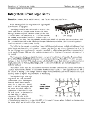
  • 1. Department of Technology and the Arts Glenforest Secondary School Computer Engineering Technology TEE2O0 Pin 1 Fig. 1: DIP Package 14 13 12 11 10 9 8 1 2 3 4 5 5 7 A1 B1 Y1 A2 B2 Y2 GND Vcc B4 A4 Y4 B3 A3 Y3 74LS00 Quad 2-Input NAND Gate Fig. 2 Integrated Circuit Logic Gates Objective: Students will be able to construct Logic Circuits using Integrated Circuits. In this activity you will use integrated circuit logic chips to build networks of logic gates. The chips you will use are from the 74xxx series of chips. These chips come in a package known as DIP (Dual In-line Package) because the plastic container has two parallel rows of pins to connect the inner circuits to a circuit board. Inside the package are networks of transistors designed to perform a wide variety of functions. Each chip is labeled with a number which indicates what the function of the chip is. Pin 1 is marked by a small circular indent or a U-shaped indent atone end of the chip; the remaining pins are numbered counterclockwise around the chip. The 7400 chip, for example, contains four 2-input NAND gates, but chips are available with all types of logic gates, timers, counters, adders and subtractors, encoders and decoders, and memory, to name a few. In fact in the late sixties and early seventies, entire computers were built by soldering thousands of these chips together on circuit boards. They are still in use today in electronic devices where the power of a complete microprocessor is not needed. The 74xxx series of chips use bipolar transistors in a type of circuit known as Transistor-Transistor Logic (TTL). While MOS and CMOS technologies are more compact and energy efficient than TTL, they are easily damaged by static electricity. TTL circuits operate with 5 Volts DC power. Each chip must have the common or negative connected to the Ground (GND) pin, and +5 volts connected to the pin marked Vcc (Common Collector Voltage). The numbers on the chips also provide other information about the contents of the package: The number is usually in the format MM74TTXX in which MM is the Manufacturer’s code, TT is the type of circuit and XX is the function of the chip. LS for example stands for a type of circuit known as Low Power Schottky, which uses Schottky diodes to improve the performance of the circuitry. The diagram at right is the logic diagram for the 7400 chip which contains four 2-input NAND gates. Note the power connections on pins 7 and 14. Pins 1 and 2 are the inputs for the first NAND gate, and the output is on pin 3. Logical 0 is represented by a voltage at or near 0V, while logical 1 is represented by a voltage close to 5 volts ( a minimum of 2.7 volts). In this activity, you will monitor the state of the outputs by connecting a resistor and an LED to the output of the gate. When the light is on it indicates that the output is high, and when it is off the output is low.
  • 2. Department of Technology and the Arts Glenforest Secondary School Computer Engineering Technology TEE2O0 4 5 6 8 10 9 ¼ 74LS00 ¼ 74LS00 Fig. 4 Procedure 1. To protect the TTL circuits, the voltage must be limited to 5 volts. Install a Voltage Regulator chip (7805) in the breadboard and connect the red lead (+) from the battery clip to pin 1 and connect the black lead (-) to pin 2. Connect a wire from pin 3 on the regulator to the positive rail on the breadboard, and connect another wire from pin 2 to the negative (or ground) rail. Fig. 3 shows what your circuit should look like. 2. Plug the 74LS00 IC into the board so that it straddles the centre divider. Plugging it in anywhere else on the board will short-circuit the opposite pins. 3. Insert two wires so that pin 7 is connected to the negative rail, and pin 14 is connected to the positive rail. 4. Connect a 220 ohm resistor from pin 6 on the 7400 chip to the anode of the LED. The cathode of the LED must be connected to ground to complete the circuit. 5. Ground both pin 4 and pin 5. 6. Connect a 9 volt battery to the battery clip and observe the results. If everything is connected correctly, you should see the LED light up. 7. Move the wires on pins 4 and 5 to the positive rail and observe the change in the output. 8. By moving the wires on pins 4 and 5 between the positive and negative rails, observe the results for all possible combinations of high and low inputs. Record the results in the form of a truth table on the answer sheet. Does the truth table correspond to the NAND gate? 9. Disconnect the battery and add wires to the circuit to produce the circuit shown in Fig 4. Following the same procedure as above, construct a truth table for this combination of gates, in which the inputs are on pins 9 and 10 and the output is still connected to pin 6. Record the results on the answer sheet and identify the gate which this circuit mimics. 1 14 74LS00 - +9V Fig. 3
  • 3. Department of Technology and the Arts Glenforest Secondary School Computer Engineering Technology TEE2O0 4 5 6 8 10 9 1 2 3 ¼ 74LS00 ¼ 74LS00 ¼ 74LS00 Fig 5 10. Being sure to disconnect the power before you change the circuit, add more wires to produce the circuit shown in Fig 5. Following the same procedure as above, construct a truth table for this combination of gates, in which one inputs is on pin 9 or10, the second input is on pin 1 or 2 and the output is still connected to pin 6. Record the results on the answer sheet and identify the gate represented by this circuit. 11. The next circuit requires the use of all the gates available on the 74LS00 IC. Once again, observe the output of the circuit with all possible combinations of inputs, and record the results on the answer sheet. 12. The final circuit requires the addition of another IC, the 74LS04. This chip is described as a Hex Inverter IC because it contains six NOT gates. Plug the new chip into the board so that it straddles the centre divider. Once again, power must be connected to pins 7 and 14. The pin numbers for the inputs and outputs of the required inverters are shown on the diagram. As before, construct a truth table and identify the gate. Fig. 6 4 5 6 8 10 9 1 2 3 11 12 13 4 5 6 8 10 9 1 2 3 ¼ 74LS00 ¼ 74LS00 ¼ 74LS00 ¼ 74LS00 Fig. 7 4 5 6 8 10 9 1 2 3 4 5 6 8 10 9 1 2 3 ¼ 74LS00 ¼ 74LS00 1/6 74LS04 1/6 74LS04 ¼ 74LS00 1 2 3 4
  • 4. Department of Technology and the Arts Glenforest Secondary School Computer Engineering Technology TEE2O0 4 5 6 8 10 9 ¼ 74LS00 ¼ 74LS00 Fig. 4 4 5 6 8 10 9 1 2 3 ¼ 74LS00 ¼ 74LS00 ¼ 74LS00 Fig 5 Answer Sheet: IC Logic Gates 8. Gate: ________________ A B y L L L H H L H H 9. Gate: ________________ A B y L L L H H L H H 10. Gate: ________________ A B y 0 0 0 1 1 0 1 1 11. Gate: ________________ A B y 0 0 0 1 1 0 1 1 12. Gate: ________________ A B y 0 0 0 1 1 0 1 1 Fig. 6 4 5 6 8 10 9 1 2 3 11 12 13 4 5 6 8 10 9 1 2 3 ¼ 74LS00 ¼ 74LS00 ¼ 74LS00 ¼ 74LS00 4 5 6 ¼ 74LS00 Fig. 7 4 5 6 8 10 9 1 2 3 4 5 6 8 10 9 1 2 3 ¼ 74LS00 ¼ 74LS00 1/6 74LS04 1/6 74LS04 ¼ 74LS00 1 2 3 4