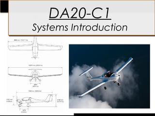
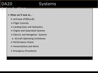
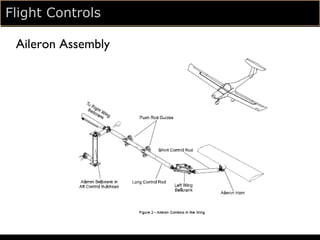
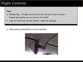
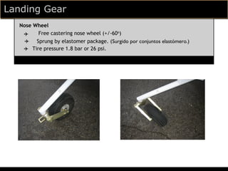
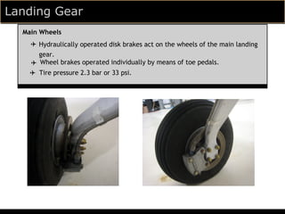
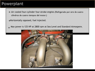
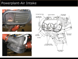
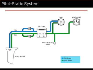
DA20-C1
Systems Introduction
DA20                              Systems
Introduction
   ✈ What we’ll look at...
     ✈ Airframe (FUSELAJE)
     ✈ Flight Controls
     ✈ Landing Gear and Hydraulics
     ✈ Engine and Associated Systems
     ✈ Electric and Navigation Systems
      ✈ Aircraft Operating Limitations
     ✈ Performance Charts
     ✈ Annunciations and Alerts

     ✈ Emergency Procedures
DA20 Airframe
  Construction Materials
      ✈ Composite aircraft; constructed mostly of Glass Fibre Reinforced
         Plastic (GFRP), although Carbon Fibre (CFRP) is used to
         strengthen (FORTALECER) where needed.
  Fuselage

          ✈ Semi-monocoque molded construction.
            Fire-resistant matting on cabin side of firewall; stainless steel
          ✈
             cladding on engine side. (revestimiento de acero inoxidable en el lado del motor).

  Wings

         ✈ Front and rear spar; top shell and bottom shell. (Delantera y trasera larguero; carcasa
  superior y la cubierta inferior).
        ✈
             Principally sandwiched construction

      ✈
   Empennage
      ✈
         T-tail design.
         Semi-monocoque sandwiche contruction
Flight Controls
   ✈ Ailerons
   ✈ Flaps
   ✈ Elevator
   ✈ Trim System
   ✈ Rudder
Flight Controls
  Ailerons
  ✈ 4 hinges (BISAGRAS).
  ✈ Aileron Balancing Weight is located at the outboard edge of aileron

  ✈   The lock nut has varnish applied (called a torque seal) which indicates changes to factory adjustment; if the varnish
      has been disturbed, flight safety may be compromised. (La tuerca de seguridad tiene el barniz aplicada (llamado un sello de
      par) lo que indica cambios en el ajuste de fábrica, si el barniz se ha alterado, la seguridad del vuelo puede verse comprometida)
Flight Controls

 Aileron Assembly


              INSERT PICTURE HERE
Flight Controls

   Flaps
   ✈ Slotted flap , 4 hinges secured by a nut and bolt (Tapa ranurada, 4
     bisagras garantizadas por una tuerca y un tornillo)
   ✈ Lock nut with lock varnish (CAPA) ; check for damage.


  ✈ Flap system protected by a circuit breaker.
Flight Controls
   Flap Settings

   ✈ Flaps electrically operated - 3 settings: cruise (UP), takeoff - 15o (T/O),
     landing - 45o (LDG).
  ✈   Note: when instrument lights are turned on, the flap indicator lights are
      dimmed (ATENUADO)
Flight Controls

  Flap Assembly
Flight Controls
  Elevator
   ✈ Steel pushrods.(VARILLAS DE ACERO)
   ✈ The bellcrank is visible next to the lower hinge of the rudder, as well as the
     elevator horn and its bearings. (La palanca acodada es visible al lado de
     la bisagra inferior del timón, así como la bocina elevador y sus cojinetes.)
Flight Controls

Elevator Assembly
Flight Controls

Trim System Assembly
Flight Controls
  Rudder
  ✈ An upper hinge and a lower hinge with rubber stops; lower hinge is available
    for visual inspection. (Una bisagra superior y la bisagra inferior con topes de
    goma, la bisagra inferior está disponible para la inspección visual.)

  ✈   Connected by cables to the rudder pedals.(Conectado por cables a los
      pedales del timón.)
Flight Controls
   ✈ Ailerons
   ✈ Flaps
   ✈ Elevator
   ✈ Trim System
   ✈ Rudder
Landing Gear
  ✈ Nose Gear
  ✈ Main Gear
  ✈ Hydraulic System
Landing Gear
  Nose Wheel
   ✈    Free castering nose wheel (+/-60o)
    ✈ Sprung by elastomer package. (Surgido por conjuntos elastómero.)
   ✈ Tire pressure 1.8 bar or 26 psi.
Landing Gear

Nose Gear Assembly
Landing Gear
  Main Wheels
    ✈ Hydraulically operated disk brakes act on the wheels of the main landing
      gear.
    ✈ Wheel brakes operated individually by means of toe pedals.
    ✈ Tire pressure 2.3 bar or 33 psi.
Hydraulic System
Landing Gear

  ✈ Nose Gear
  ✈ Main Gear
  ✈ Hydraulic System
Engine and Associated
Systems
   ✈ Engine
   ✈ Fuel System
   ✈ Lubrication System
Powerplant
   ✈ Air cooled four-cylinder four-stroke engine.(Refrigerado por aire de cuatro
     cilindros de cuatro tiempos del motor.)

   ✈Horizontally opposed, fuel injected.


   ✈ Max power is 125 HP at 2800 rpm at Sea Level and Standard Atmospere.
Powerplant-Air Intake
Fuel System
  Fuel Pumps
  ✈ Equipped with both a mechanical and a 2 speed electric fuel pump.
  ✈ Mechanical pump used for fuel supply during normal operation.
  ✈ Electric pump is pilot controlled via the FUEL PUMP switch and should be on at
    engine start, during takeoff and landing, and during low throttle operations.

  Fuel Prime
  ✈ High speed setting of electric pump, used for engine start.
Fuel System
  Fuel Tank

  ✈ Located behind seats under baggage compartment.

  ✈ Two drains must be checked during the preflight inspection.
Fuel System
Lubrication System
Oil System
   ✈ During the first 50 hours of operation of a new or overhauled engine,
     mineral oil should be used.
   ✈ Oil Quantity:
                Minimum 4 Quarts.
                 Maximum 6 Quarts.
   ✈ Oil Temperature:
               Maximum 240 F.
Engine and Associated
Systems
   ✈ Engine
   ✈ Fuel System
   ✈ Lubrication System
Electrical System

   ✈ Storage
     Power is stored in a12 V 10 amp-hour or more lead-acid battery, mounted
     on the left hand side of the engine compartment.
Electrical System
Electrical System
   Power Generation
   ✈
   ✈ Power is generated by a 40 ampere alternator, mounted on the front of the
     engine.
Ignition System
   During Start
  ✈ System powered by ‘SlickSTART’ electric start boost system.
  ✈ Delivers a shower of sparks during the engine start sequence to provide better
    ignition characteristics.
   After Start
   ✈ Uses a conventional magneto system.
Electrical System
  ✈ Battery/Storage
  ✈ Alternator/Generator
  ✈ Ignition
The Pitot Static System
  The Air Data Computer
  ✈ With respect to the G500, pitot static measurements are performed by the
    Air Data Computer.
   ✈ The airspeed and altimeter back-up instruments work on the same principle
     as standard pitot static instruments.
Pitot-Static System

Sistemas

  • 1.
  • 2.
    DA20 Systems Introduction ✈ What we’ll look at... ✈ Airframe (FUSELAJE) ✈ Flight Controls ✈ Landing Gear and Hydraulics ✈ Engine and Associated Systems ✈ Electric and Navigation Systems ✈ Aircraft Operating Limitations ✈ Performance Charts ✈ Annunciations and Alerts ✈ Emergency Procedures
  • 3.
    DA20 Airframe Construction Materials ✈ Composite aircraft; constructed mostly of Glass Fibre Reinforced Plastic (GFRP), although Carbon Fibre (CFRP) is used to strengthen (FORTALECER) where needed. Fuselage ✈ Semi-monocoque molded construction. Fire-resistant matting on cabin side of firewall; stainless steel ✈ cladding on engine side. (revestimiento de acero inoxidable en el lado del motor). Wings ✈ Front and rear spar; top shell and bottom shell. (Delantera y trasera larguero; carcasa superior y la cubierta inferior). ✈ Principally sandwiched construction ✈ Empennage ✈ T-tail design. Semi-monocoque sandwiche contruction
  • 4.
    Flight Controls ✈ Ailerons ✈ Flaps ✈ Elevator ✈ Trim System ✈ Rudder
  • 5.
    Flight Controls Ailerons ✈ 4 hinges (BISAGRAS). ✈ Aileron Balancing Weight is located at the outboard edge of aileron ✈ The lock nut has varnish applied (called a torque seal) which indicates changes to factory adjustment; if the varnish has been disturbed, flight safety may be compromised. (La tuerca de seguridad tiene el barniz aplicada (llamado un sello de par) lo que indica cambios en el ajuste de fábrica, si el barniz se ha alterado, la seguridad del vuelo puede verse comprometida)
  • 6.
    Flight Controls AileronAssembly INSERT PICTURE HERE
  • 7.
    Flight Controls Flaps ✈ Slotted flap , 4 hinges secured by a nut and bolt (Tapa ranurada, 4 bisagras garantizadas por una tuerca y un tornillo) ✈ Lock nut with lock varnish (CAPA) ; check for damage. ✈ Flap system protected by a circuit breaker.
  • 8.
    Flight Controls Flap Settings ✈ Flaps electrically operated - 3 settings: cruise (UP), takeoff - 15o (T/O), landing - 45o (LDG). ✈ Note: when instrument lights are turned on, the flap indicator lights are dimmed (ATENUADO)
  • 9.
    Flight Controls Flap Assembly
  • 10.
    Flight Controls Elevator ✈ Steel pushrods.(VARILLAS DE ACERO) ✈ The bellcrank is visible next to the lower hinge of the rudder, as well as the elevator horn and its bearings. (La palanca acodada es visible al lado de la bisagra inferior del timón, así como la bocina elevador y sus cojinetes.)
  • 11.
  • 12.
  • 13.
    Flight Controls Rudder ✈ An upper hinge and a lower hinge with rubber stops; lower hinge is available for visual inspection. (Una bisagra superior y la bisagra inferior con topes de goma, la bisagra inferior está disponible para la inspección visual.) ✈ Connected by cables to the rudder pedals.(Conectado por cables a los pedales del timón.)
  • 14.
    Flight Controls ✈ Ailerons ✈ Flaps ✈ Elevator ✈ Trim System ✈ Rudder
  • 15.
    Landing Gear ✈ Nose Gear ✈ Main Gear ✈ Hydraulic System
  • 16.
    Landing Gear Nose Wheel ✈ Free castering nose wheel (+/-60o) ✈ Sprung by elastomer package. (Surgido por conjuntos elastómero.) ✈ Tire pressure 1.8 bar or 26 psi.
  • 17.
  • 18.
    Landing Gear Main Wheels ✈ Hydraulically operated disk brakes act on the wheels of the main landing gear. ✈ Wheel brakes operated individually by means of toe pedals. ✈ Tire pressure 2.3 bar or 33 psi.
  • 19.
  • 20.
    Landing Gear ✈ Nose Gear ✈ Main Gear ✈ Hydraulic System
  • 21.
    Engine and Associated Systems ✈ Engine ✈ Fuel System ✈ Lubrication System
  • 22.
    Powerplant ✈ Air cooled four-cylinder four-stroke engine.(Refrigerado por aire de cuatro cilindros de cuatro tiempos del motor.) ✈Horizontally opposed, fuel injected. ✈ Max power is 125 HP at 2800 rpm at Sea Level and Standard Atmospere.
  • 23.
  • 24.
    Fuel System Fuel Pumps ✈ Equipped with both a mechanical and a 2 speed electric fuel pump. ✈ Mechanical pump used for fuel supply during normal operation. ✈ Electric pump is pilot controlled via the FUEL PUMP switch and should be on at engine start, during takeoff and landing, and during low throttle operations. Fuel Prime ✈ High speed setting of electric pump, used for engine start.
  • 25.
    Fuel System Fuel Tank ✈ Located behind seats under baggage compartment. ✈ Two drains must be checked during the preflight inspection.
  • 26.
  • 27.
  • 28.
    Oil System ✈ During the first 50 hours of operation of a new or overhauled engine, mineral oil should be used. ✈ Oil Quantity: Minimum 4 Quarts. Maximum 6 Quarts. ✈ Oil Temperature: Maximum 240 F.
  • 29.
    Engine and Associated Systems ✈ Engine ✈ Fuel System ✈ Lubrication System
  • 30.
    Electrical System ✈ Storage Power is stored in a12 V 10 amp-hour or more lead-acid battery, mounted on the left hand side of the engine compartment.
  • 31.
  • 32.
    Electrical System Power Generation ✈ ✈ Power is generated by a 40 ampere alternator, mounted on the front of the engine.
  • 33.
    Ignition System During Start ✈ System powered by ‘SlickSTART’ electric start boost system. ✈ Delivers a shower of sparks during the engine start sequence to provide better ignition characteristics. After Start ✈ Uses a conventional magneto system.
  • 34.
    Electrical System ✈ Battery/Storage ✈ Alternator/Generator ✈ Ignition
  • 35.
    The Pitot StaticSystem The Air Data Computer ✈ With respect to the G500, pitot static measurements are performed by the Air Data Computer. ✈ The airspeed and altimeter back-up instruments work on the same principle as standard pitot static instruments.
  • 36.

Editor's Notes

  • #4 Strengthen where needed – the spar, main bulkhead, ailerons and flaps.
  • #6 pictures/movies: control linkages throughout airplane? hinges/roll pins/varnish
  • #7 pictures/movies: control linkages throughout airplane? hinges/roll pins/varnish
  • #8 videos/movies; flaps extending/retracting w/ lights (needs to be dark) circuit breaker NEW FLAPS MOVIE
  • #9 videos/movies; flaps extending/retracting w/ lights (needs to be dark) circuit breaker NEW FLAPS MOVIE
  • #10 videos/movies; flaps extending/retracting w/ lights (needs to be dark) circuit breaker NEW FLAPS MOVIE
  • #11 videos/movies; bellcranks/bearings elevator moving up and down
  • #12 videos/movies; bellcranks/bearings elevator moving up and down
  • #13 videos/movies; bellcranks/bearings elevator moving up and down
  • #20 - operate parking brake; pull lever down until it catches, pump brakes several times to build up pressure. -if copilot’s brakes fail, pilot’s are still operational; if pilot’s fail, both fail. -check for leaks around main wheels as part of every walkaround.
  • #25 -equipped with both a mechanical and an electric fuel pump; mechanical for normal fuel supply, electrical pilot controlled -electrical for emergency and backup; turned on via FUEL PUMP switch during engine start, takeoff, and landing, as well as when switching tanks FUEL PUMP SWITCH PICTURE/FUEL SELECTOR PICTURE DO WE WANT ANYTHING ON FUEL TANKS OR THE FUEL QUANTITY MEASURING DEVICE?