Download as PDF, PPTX


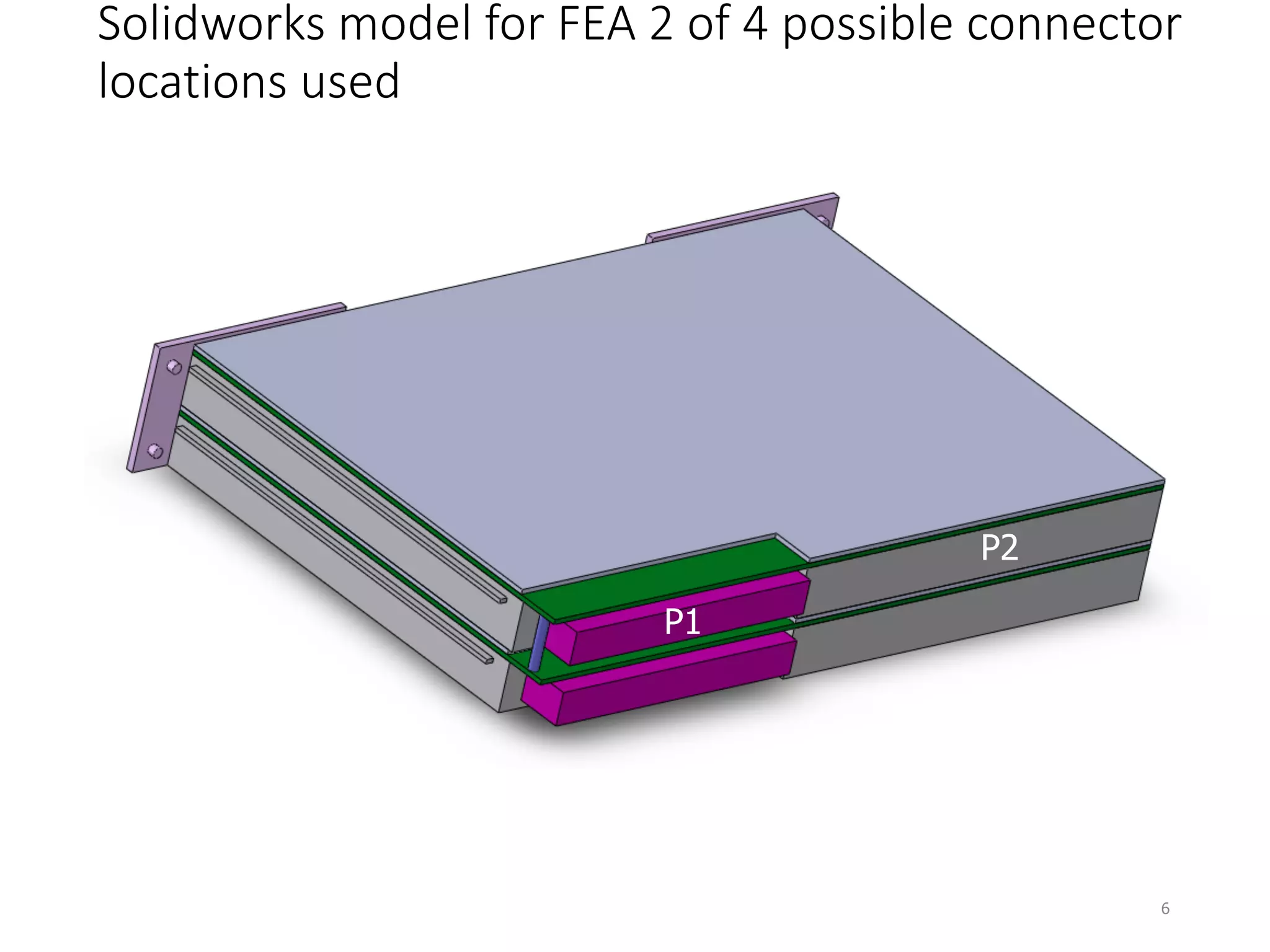
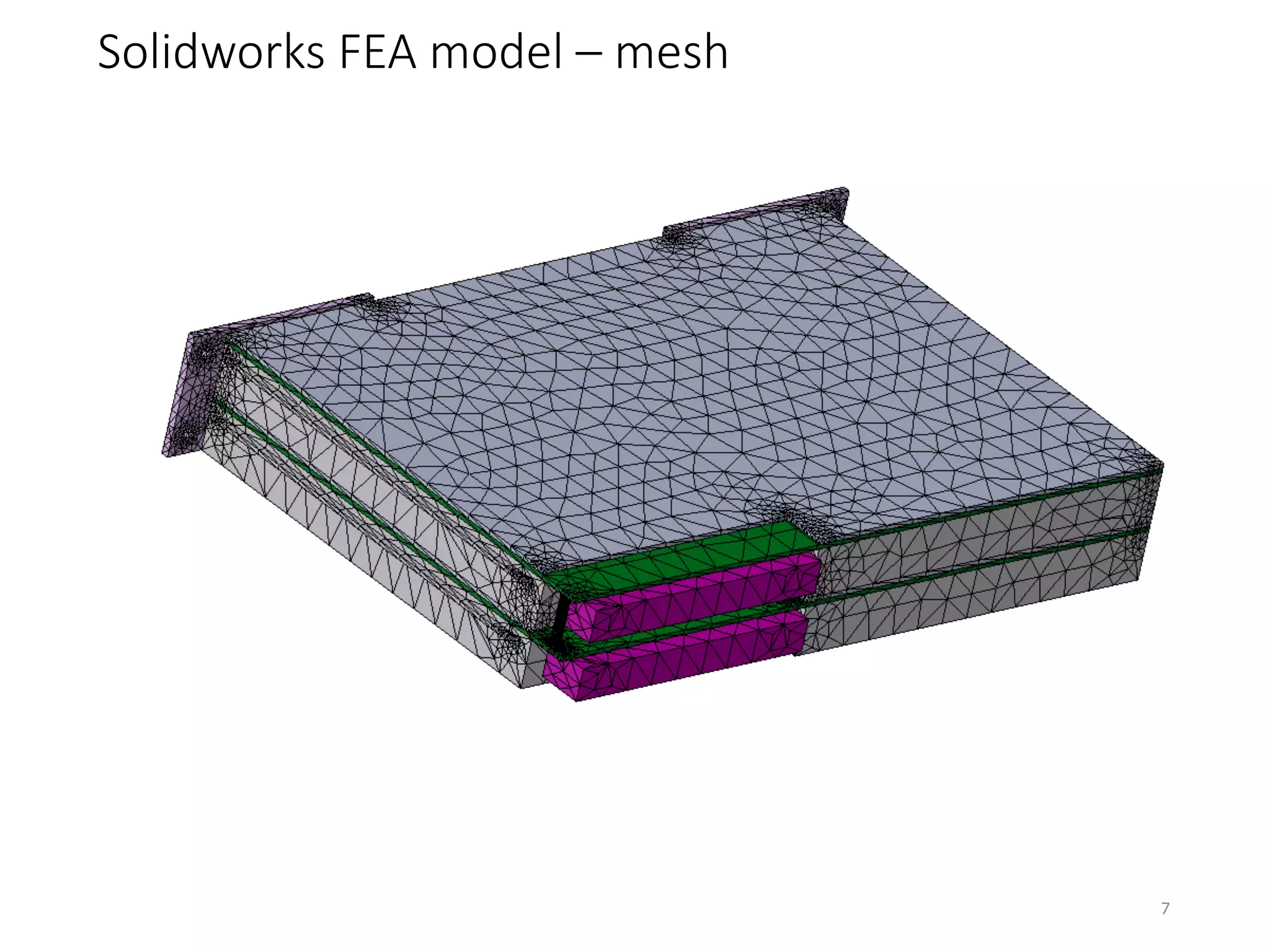


The document evaluates the vibration response of a 6u electronics assembly at the crystal oscillator location using SolidWorks FEA, subjecting it to random vibration levels of 0.04 gsq/hz within a frequency range of 20-2000 Hz. The maximum response at the crystal location is approximately 105 g's under z-axis vibration. Recommendations for reducing peak g levels include relocating the crystal toward the front panel and supporting the module at specific connector locations.