Download as PDF, PPTX
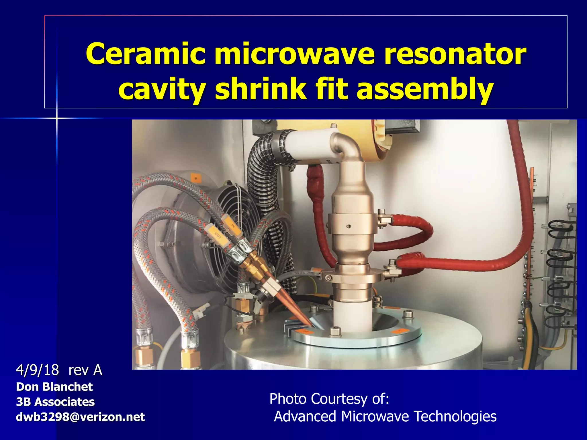


This document summarizes the assembly process for a ceramic microwave resonator cavity using a shrink fit technique. Key steps include heating the aluminum housing to expand it, inserting the ceramic puck using an alignment fixture, and allowing the assembly to cool which causes the housing to contract around the puck, holding it firmly in place through compression. Finite element analysis confirms the ceramic is held safely in compression while the housing experiences some permanent plastic deformation within its yield strength to form an interference fit.


