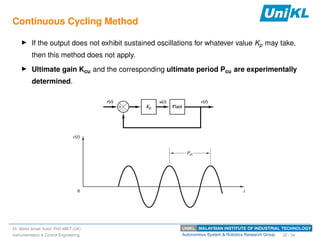
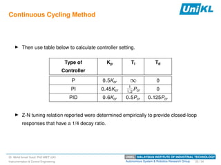
UNIKL MALAYSIAN INSTITUTE OF INDUSTRIAL TECHNOLOGY
Autonomous System & Robotics Research Group
Recaps
I In the previous lesson, we learnt on process dynamic.
I In general, process can be categorised (1) non-integrating, (2) integrating.
I Common control strategy
I feedback control;
I feedforward control;
I cascade;
I ratio control;
I selector control;
I More advance control strategy
I Linear Quadratic Regulator;
I Fuzzy Logic Controller;
I Model Predictive Controller;
Dr. Mohd Ismail Yusof, PhD MIET (UK)
Instrumentation & Control Engineering 3 / 34
Motivation
UNIKL MALAYSIAN INSTITUTE OF INDUSTRIAL TECHNOLOGY
Autonomous System & Robotics Research Group
Control Block Scheme
Assume a heat-exchanger control loop example. It is non-integrating (self-regulate) process
with time-delay.
Dr. Mohd Ismail Yusof, PhD MIET (UK)
Instrumentation & Control Engineering 5 / 34
UNIKL MALAYSIAN INSTITUTE OF INDUSTRIAL TECHNOLOGY
Autonomous System & Robotics Research Group
Control Block Scheme (cont)
1. Sense. Measure the current condition of the process using a sensor, which can be a
thermocouple or RTD transmitter.
2. Compare. Evaluate the measurement of the current condition against the set point
using an electronic PID controller.
3. Respond. Reacts to any error that may exist between the measured temperature
value and the temperature set point by generating a corrective pneumatic signal.
4. Affect. Actuate the control valve that will produce a change in the process variable.
Dr. Mohd Ismail Yusof, PhD MIET (UK)
Instrumentation & Control Engineering 6 / 34
UNIKL MALAYSIAN INSTITUTE OF INDUSTRIAL TECHNOLOGY
Autonomous System & Robotics Research Group
Control Block Scheme (cont)
The simplified P&ID for heat-exchanger.
Dr. Mohd Ismail Yusof, PhD MIET (UK)
Instrumentation & Control Engineering 7 / 34
UNIKL MALAYSIAN INSTITUTE OF INDUSTRIAL TECHNOLOGY
Autonomous System & Robotics Research Group
Control Block Scheme (cont)
Control system block diagram visualisation,
Dr. Mohd Ismail Yusof, PhD MIET (UK)
Instrumentation & Control Engineering 8 / 34
Proportional-Integral-Derivative Controller
UNIKL MALAYSIAN INSTITUTE OF INDUSTRIAL TECHNOLOGY
Autonomous System & Robotics Research Group
PID Controller
I PID (Proportional-Integral-Derivative) is a type of
controller that is widely used in manufacturing
industry.
I Conventional PID controller is an electronic
devices. Usually it is installed at control panel
near field.
I PID control algorithm can also be programmed in
PLC and DCS software.
I PID controller (or algorithm) give some sort of
transient and dynamics that we wanted it to be
rather than transient response that it naturally
have.
Dr. Mohd Ismail Yusof, PhD MIET (UK)
Instrumentation & Control Engineering 10 / 34
UNIKL MALAYSIAN INSTITUTE OF INDUSTRIAL TECHNOLOGY
Autonomous System & Robotics Research Group
PID Form
Three Common PID Forms
I Parallel Form.
I Standard, aka ISA Form.
I Series, aka Classical Form.
DeltaV has choice
I Standard (Default)
I Series
Dr. Mohd Ismail Yusof, PhD MIET (UK)
Instrumentation & Control Engineering 11 / 34
UNIKL MALAYSIAN INSTITUTE OF INDUSTRIAL TECHNOLOGY
Autonomous System & Robotics Research Group
PID Controller Function-Effect on Proportional gain only
I The use of proportional control alone has a large drawback – offset
I As long as the liquid flow remains constant, the liquid temperature will
remain at its set point.
I But, if the operator should increase/decrease the liquid flow, the liquid
temperature will begin to change due to the changes of liquid flow.
I While the liquid temperature change, the error increases and our
proportional controller increases the controller output proportional to this
error.
I Consequently, the valve controlling the flow into the tank opens wider and
more steam flows into the shell.
I As the temperature continues to decrease, the valve continues to open
until it gets to a point where the measured temperature again matches
the setpoint.
I At this point the liquid temperature (and error) will remain constant.
Because the error remains constant our P-controller will keep its output
constant and the control valve will hold its position.
I The system now remains at balance, but the liquid temperature remains
below its set point. This residual sustained error is called Offset.
Dr. Mohd Ismail Yusof, PhD MIET (UK)
Instrumentation & Control Engineering 12 / 34
UNIKL MALAYSIAN INSTITUTE OF INDUSTRIAL TECHNOLOGY
Autonomous System & Robotics Research Group
PID Controller Function-Proportional action summary
Features
I Proportional mode responds only to change in error.
I Proportional mode alone will not return the PV to SP.
Advantages
I Simple.
Disadvantages
I Offset.
Dr. Mohd Ismail Yusof, PhD MIET (UK)
Instrumentation & Control Engineering 13 / 34
UNIKL MALAYSIAN INSTITUTE OF INDUSTRIAL TECHNOLOGY
Autonomous System & Robotics Research Group
PID Controller Function-P+I action summary
Features
I Output is repeat of the proportional action as long as error exists.
I The units are in terms of repeats per minute
Advantages
I Eliminates error.
Disadvantages
I Reset windup and possible overshoot.
Dr. Mohd Ismail Yusof, PhD MIET (UK)
Instrumentation & Control Engineering 14 / 34
UNIKL MALAYSIAN INSTITUTE OF INDUSTRIAL TECHNOLOGY
Autonomous System & Robotics Research Group
PID Controller Function-P+D action summary
Features
I A function of the speed of change of the error.
I The units are minutes.
Advantages
I Rapid output reduces the time that is required to return PV to SP in slow process.
Disadvantages
I Dramatically amplify noisy signals, can cause cycling in fast process.
Dr. Mohd Ismail Yusof, PhD MIET (UK)
Instrumentation & Control Engineering 15 / 34
UNIKL MALAYSIAN INSTITUTE OF INDUSTRIAL TECHNOLOGY
Autonomous System & Robotics Research Group
Selection of Control Mode
I Not every process requires a full PID control strategy.
I If a small offset has no impact on the process, then P control alone may be sufficient.
I PI control is used where no offset can be tolerated, where noise may be present, and
where excessive dead time is not a problem.
I In processes where no offset can be tolerated, no noise is present, and where dead
time is an issue, customers ca use full PID control.
Dr. Mohd Ismail Yusof, PhD MIET (UK)
Instrumentation & Control Engineering 16 / 34
Fundamental of PID Control Parameter
Tuning
UNIKL MALAYSIAN INSTITUTE OF INDUSTRIAL TECHNOLOGY
Autonomous System & Robotics Research Group
Online Controller Tuning
I The control systems for modern industrial plants typically include thousands of
individual control loops.
I During control system design, preliminary controller settings are specified based on
process knowledge, control objectives, and prior experience.
I After a controller is installed, the preliminary settings often prove to be satisfactory.
I But for critical control loops, the preliminary settings may have to be adjusted in order
to achieve satisfactory control.
Dr. Mohd Ismail Yusof, PhD MIET (UK)
Instrumentation & Control Engineering 18 / 34
UNIKL MALAYSIAN INSTITUTE OF INDUSTRIAL TECHNOLOGY
Autonomous System & Robotics Research Group
Online Controller Tuning
From previous knowledge, several observations made:
I Controller tuning inevitably involves a tradeoff between performance and robustness.
I Controller settings do not have to be precisely determined.
I For most plants, it is not feasible to manually tune each controller.
I Diagnostic techniques for monitoring control system performance are available.
Dr. Mohd Ismail Yusof, PhD MIET (UK)
Instrumentation & Control Engineering 19 / 34
UNIKL MALAYSIAN INSTITUTE OF INDUSTRIAL TECHNOLOGY
Autonomous System & Robotics Research Group
Continuous Cycling Method
I Ziegler and Nichols (1942) published a classic paper that introduced the continuous
cycling method for controller tuning.
I Z-N tuning relation have enormous impact on both process control research and
practice.
I Despite serious shortcoming, the Z-N relations and (various modifications) have been
widely used as a benchmark in comparisons of tuning relations.
Dr. Mohd Ismail Yusof, PhD MIET (UK)
Instrumentation & Control Engineering 20 / 34
UNIKL MALAYSIAN INSTITUTE OF INDUSTRIAL TECHNOLOGY
Autonomous System & Robotics Research Group
Continuous Cycling Method
Step for Z-N tuning relation is given as:
I After process has reached steady-state, introduce proportional only control.
I First set ⌧I = 1 and ⌧D = 0. i.e, using proportional control action only.
I Introduce a small, momentary set-point change so that controlled variable moves away
from the set-point.
I Increase Kc from 0 to a critical value Kcu at which the output first exhibits
sustained oscillations.
Dr. Mohd Ismail Yusof, PhD MIET (UK)
Instrumentation & Control Engineering 21 / 34
UNIKL MALAYSIAN INSTITUTE OF INDUSTRIAL TECHNOLOGY
Autonomous System & Robotics Research Group
Continuous Cycling Method
I If the output does not exhibit sustained oscillations for whatever value Kp may take,
then this method does not apply.
I Ultimate gain Kcu and the corresponding ultimate period Pcu are experimentally
determined.
Dr. Mohd Ismail Yusof, PhD MIET (UK)
Instrumentation & Control Engineering 22 / 34
UNIKL MALAYSIAN INSTITUTE OF INDUSTRIAL TECHNOLOGY
Autonomous System & Robotics Research Group
Continuous Cycling Method
I Then use table below to calculate controller setting.
Type of
Controller
Kp Ti Td
P 0.5Kcr 1 0
PI 0.45Kcr
1
1.2
Pcr 0
PID 0.6Kcr 0.5Pcr 0.125Pcr
I Z-N tuning relation reported were determined empirically to provide closed-loop
responses that have a 1/4 decay ratio.
Dr. Mohd Ismail Yusof, PhD MIET (UK)
Instrumentation & Control Engineering 23 / 34
UNIKL MALAYSIAN INSTITUTE OF INDUSTRIAL TECHNOLOGY
Autonomous System & Robotics Research Group
Example
Example 1
Find PID controller setting
using Z-N setting with
Kcu = 7.88 and
Pcu = 11.66
Dr. Mohd Ismail Yusof, PhD MIET (UK)
Instrumentation & Control Engineering 24 / 34
UNIKL MALAYSIAN INSTITUTE OF INDUSTRIAL TECHNOLOGY
Autonomous System & Robotics Research Group
Continuous Cycling Method
Major disadvantages of Z-N continuous cycling method:
1. The trial-and-error determination of Kcu and Pcu can be quite time consuming if the
process dynamics are slow.
2. For many applications, continuous cycling method is objectionable because the
process is pushed to stability limit. Consequently, if external disturbances or process
changes occur duirng the test, unstable operation or a hazardous situation could
result.
3. This tuning procedure is not applicable to integrating or open-loop unstable processes,
because their control loops typically are unstable at both high and low values of Kc,
while being stable for intermediate values.
Dr. Mohd Ismail Yusof, PhD MIET (UK)
Instrumentation & Control Engineering 25 / 34
UNIKL MALAYSIAN INSTITUTE OF INDUSTRIAL TECHNOLOGY
Autonomous System & Robotics Research Group
Step Test Method
I Simple experimental procedure for online tuning method.
I Experiment is done in open loop mode.
I After process has reached steady-state, the controller is placed in the manual mode.
I Then introduced small step change in the controller output.
Dr. Mohd Ismail Yusof, PhD MIET (UK)
Instrumentation & Control Engineering 26 / 34
UNIKL MALAYSIAN INSTITUTE OF INDUSTRIAL TECHNOLOGY
Autonomous System & Robotics Research Group
Step Test Method
I Obtained output response from unit step input response via experiment.
I Unit step input exhibits S-shaped curve output if the plant involves neither
integrator(s) nor dominant complex-conjugate poles.
I The S-shaped curve characterised by 2 constants, (i) time delay ✓ (or td, L ), and (ii)
time constant ⌧ (or T).
I These constants are determined by drawing a tangent line at the inflection point of
S-shaped curve.
Dr. Mohd Ismail Yusof, PhD MIET (UK)
Instrumentation & Control Engineering 27 / 34
UNIKL MALAYSIAN INSTITUTE OF INDUSTRIAL TECHNOLOGY
Autonomous System & Robotics Research Group
Step Test Method
I Intersection of tangent line to time axis (i.e., y = 0) indicate t0.
I Intersection of tangent line to steady-state output line (c (t) = K) indicate t1.
I TF can be approximated by first-order system with transport lag,
C (s)
R (s)
=
Ke td s
⌧s + 1
.
Dr. Mohd Ismail Yusof, PhD MIET (UK)
Instrumentation & Control Engineering 28 / 34
UNIKL MALAYSIAN INSTITUTE OF INDUSTRIAL TECHNOLOGY
Autonomous System & Robotics Research Group
Step Test Method
Dr. Mohd Ismail Yusof, PhD MIET (UK)
Instrumentation & Control Engineering 29 / 34
UNIKL MALAYSIAN INSTITUTE OF INDUSTRIAL TECHNOLOGY
Autonomous System & Robotics Research Group
Step Test Method
Type of
Controller
Kp ⌧I Td
P
⌧
✓ 1 0
PI 0.9
⌧
✓
✓
0.3
0
PID 1.2
⌧
✓ 2✓ 0.5✓
Dr. Mohd Ismail Yusof, PhD MIET (UK)
Instrumentation & Control Engineering 30 / 34
UNIKL MALAYSIAN INSTITUTE OF INDUSTRIAL TECHNOLOGY
Autonomous System & Robotics Research Group
Example
Example 2
Parameter for heat exchanger process denoted by,
I Tin is the inlet temperature,
I Tout is the exit temperature,
I Tout_mea is the temperature measurement in mA , and
I Ps is steam pressure.
During an open-loop experimental test, the steam pressure, Ps, was suddenly changed from
18 to 20 psig and the step response output, Tout_mea, shown in Figure 2. At the nominal
conditions, the control valve and current-to-pressure transducers have gains of
KV = 0.9 psi/psi and KIP = 0.75 psi/mA, respectively. Determine appropriate PID
controller settings using process reaction curve method.
Dr. Mohd Ismail Yusof, PhD MIET (UK)
Instrumentation & Control Engineering 31 / 34
UNIKL MALAYSIAN INSTITUTE OF INDUSTRIAL TECHNOLOGY
Autonomous System & Robotics Research Group
Example
Example 2
Figure 1: Heat exchanger process.
Dr. Mohd Ismail Yusof, PhD MIET (UK)
Instrumentation & Control Engineering 32 / 34
UNIKL MALAYSIAN INSTITUTE OF INDUSTRIAL TECHNOLOGY
Autonomous System & Robotics Research Group
Example
Example 2
Figure 2: Step response output.
Dr. Mohd Ismail Yusof, PhD MIET (UK)
Instrumentation & Control Engineering 33 / 34

6_P-I-D_Controller.pdf

  • 1.
    UNIKL MALAYSIAN INSTITUTEOF INDUSTRIAL TECHNOLOGY Autonomous System & Robotics Research Group Recaps I In the previous lesson, we learnt on process dynamic. I In general, process can be categorised (1) non-integrating, (2) integrating. I Common control strategy I feedback control; I feedforward control; I cascade; I ratio control; I selector control; I More advance control strategy I Linear Quadratic Regulator; I Fuzzy Logic Controller; I Model Predictive Controller; Dr. Mohd Ismail Yusof, PhD MIET (UK) Instrumentation & Control Engineering 3 / 34
  • 2.
  • 3.
    UNIKL MALAYSIAN INSTITUTEOF INDUSTRIAL TECHNOLOGY Autonomous System & Robotics Research Group Control Block Scheme Assume a heat-exchanger control loop example. It is non-integrating (self-regulate) process with time-delay. Dr. Mohd Ismail Yusof, PhD MIET (UK) Instrumentation & Control Engineering 5 / 34
  • 4.
    UNIKL MALAYSIAN INSTITUTEOF INDUSTRIAL TECHNOLOGY Autonomous System & Robotics Research Group Control Block Scheme (cont) 1. Sense. Measure the current condition of the process using a sensor, which can be a thermocouple or RTD transmitter. 2. Compare. Evaluate the measurement of the current condition against the set point using an electronic PID controller. 3. Respond. Reacts to any error that may exist between the measured temperature value and the temperature set point by generating a corrective pneumatic signal. 4. Affect. Actuate the control valve that will produce a change in the process variable. Dr. Mohd Ismail Yusof, PhD MIET (UK) Instrumentation & Control Engineering 6 / 34
  • 5.
    UNIKL MALAYSIAN INSTITUTEOF INDUSTRIAL TECHNOLOGY Autonomous System & Robotics Research Group Control Block Scheme (cont) The simplified P&ID for heat-exchanger. Dr. Mohd Ismail Yusof, PhD MIET (UK) Instrumentation & Control Engineering 7 / 34
  • 6.
    UNIKL MALAYSIAN INSTITUTEOF INDUSTRIAL TECHNOLOGY Autonomous System & Robotics Research Group Control Block Scheme (cont) Control system block diagram visualisation, Dr. Mohd Ismail Yusof, PhD MIET (UK) Instrumentation & Control Engineering 8 / 34
  • 7.
  • 8.
    UNIKL MALAYSIAN INSTITUTEOF INDUSTRIAL TECHNOLOGY Autonomous System & Robotics Research Group PID Controller I PID (Proportional-Integral-Derivative) is a type of controller that is widely used in manufacturing industry. I Conventional PID controller is an electronic devices. Usually it is installed at control panel near field. I PID control algorithm can also be programmed in PLC and DCS software. I PID controller (or algorithm) give some sort of transient and dynamics that we wanted it to be rather than transient response that it naturally have. Dr. Mohd Ismail Yusof, PhD MIET (UK) Instrumentation & Control Engineering 10 / 34
  • 9.
    UNIKL MALAYSIAN INSTITUTEOF INDUSTRIAL TECHNOLOGY Autonomous System & Robotics Research Group PID Form Three Common PID Forms I Parallel Form. I Standard, aka ISA Form. I Series, aka Classical Form. DeltaV has choice I Standard (Default) I Series Dr. Mohd Ismail Yusof, PhD MIET (UK) Instrumentation & Control Engineering 11 / 34
  • 10.
    UNIKL MALAYSIAN INSTITUTEOF INDUSTRIAL TECHNOLOGY Autonomous System & Robotics Research Group PID Controller Function-Effect on Proportional gain only I The use of proportional control alone has a large drawback – offset I As long as the liquid flow remains constant, the liquid temperature will remain at its set point. I But, if the operator should increase/decrease the liquid flow, the liquid temperature will begin to change due to the changes of liquid flow. I While the liquid temperature change, the error increases and our proportional controller increases the controller output proportional to this error. I Consequently, the valve controlling the flow into the tank opens wider and more steam flows into the shell. I As the temperature continues to decrease, the valve continues to open until it gets to a point where the measured temperature again matches the setpoint. I At this point the liquid temperature (and error) will remain constant. Because the error remains constant our P-controller will keep its output constant and the control valve will hold its position. I The system now remains at balance, but the liquid temperature remains below its set point. This residual sustained error is called Offset. Dr. Mohd Ismail Yusof, PhD MIET (UK) Instrumentation & Control Engineering 12 / 34
  • 11.
    UNIKL MALAYSIAN INSTITUTEOF INDUSTRIAL TECHNOLOGY Autonomous System & Robotics Research Group PID Controller Function-Proportional action summary Features I Proportional mode responds only to change in error. I Proportional mode alone will not return the PV to SP. Advantages I Simple. Disadvantages I Offset. Dr. Mohd Ismail Yusof, PhD MIET (UK) Instrumentation & Control Engineering 13 / 34
  • 12.
    UNIKL MALAYSIAN INSTITUTEOF INDUSTRIAL TECHNOLOGY Autonomous System & Robotics Research Group PID Controller Function-P+I action summary Features I Output is repeat of the proportional action as long as error exists. I The units are in terms of repeats per minute Advantages I Eliminates error. Disadvantages I Reset windup and possible overshoot. Dr. Mohd Ismail Yusof, PhD MIET (UK) Instrumentation & Control Engineering 14 / 34
  • 13.
    UNIKL MALAYSIAN INSTITUTEOF INDUSTRIAL TECHNOLOGY Autonomous System & Robotics Research Group PID Controller Function-P+D action summary Features I A function of the speed of change of the error. I The units are minutes. Advantages I Rapid output reduces the time that is required to return PV to SP in slow process. Disadvantages I Dramatically amplify noisy signals, can cause cycling in fast process. Dr. Mohd Ismail Yusof, PhD MIET (UK) Instrumentation & Control Engineering 15 / 34
  • 14.
    UNIKL MALAYSIAN INSTITUTEOF INDUSTRIAL TECHNOLOGY Autonomous System & Robotics Research Group Selection of Control Mode I Not every process requires a full PID control strategy. I If a small offset has no impact on the process, then P control alone may be sufficient. I PI control is used where no offset can be tolerated, where noise may be present, and where excessive dead time is not a problem. I In processes where no offset can be tolerated, no noise is present, and where dead time is an issue, customers ca use full PID control. Dr. Mohd Ismail Yusof, PhD MIET (UK) Instrumentation & Control Engineering 16 / 34
  • 15.
    Fundamental of PIDControl Parameter Tuning
  • 16.
    UNIKL MALAYSIAN INSTITUTEOF INDUSTRIAL TECHNOLOGY Autonomous System & Robotics Research Group Online Controller Tuning I The control systems for modern industrial plants typically include thousands of individual control loops. I During control system design, preliminary controller settings are specified based on process knowledge, control objectives, and prior experience. I After a controller is installed, the preliminary settings often prove to be satisfactory. I But for critical control loops, the preliminary settings may have to be adjusted in order to achieve satisfactory control. Dr. Mohd Ismail Yusof, PhD MIET (UK) Instrumentation & Control Engineering 18 / 34
  • 17.
    UNIKL MALAYSIAN INSTITUTEOF INDUSTRIAL TECHNOLOGY Autonomous System & Robotics Research Group Online Controller Tuning From previous knowledge, several observations made: I Controller tuning inevitably involves a tradeoff between performance and robustness. I Controller settings do not have to be precisely determined. I For most plants, it is not feasible to manually tune each controller. I Diagnostic techniques for monitoring control system performance are available. Dr. Mohd Ismail Yusof, PhD MIET (UK) Instrumentation & Control Engineering 19 / 34
  • 18.
    UNIKL MALAYSIAN INSTITUTEOF INDUSTRIAL TECHNOLOGY Autonomous System & Robotics Research Group Continuous Cycling Method I Ziegler and Nichols (1942) published a classic paper that introduced the continuous cycling method for controller tuning. I Z-N tuning relation have enormous impact on both process control research and practice. I Despite serious shortcoming, the Z-N relations and (various modifications) have been widely used as a benchmark in comparisons of tuning relations. Dr. Mohd Ismail Yusof, PhD MIET (UK) Instrumentation & Control Engineering 20 / 34
  • 19.
    UNIKL MALAYSIAN INSTITUTEOF INDUSTRIAL TECHNOLOGY Autonomous System & Robotics Research Group Continuous Cycling Method Step for Z-N tuning relation is given as: I After process has reached steady-state, introduce proportional only control. I First set ⌧I = 1 and ⌧D = 0. i.e, using proportional control action only. I Introduce a small, momentary set-point change so that controlled variable moves away from the set-point. I Increase Kc from 0 to a critical value Kcu at which the output first exhibits sustained oscillations. Dr. Mohd Ismail Yusof, PhD MIET (UK) Instrumentation & Control Engineering 21 / 34
  • 20.
    UNIKL MALAYSIAN INSTITUTEOF INDUSTRIAL TECHNOLOGY Autonomous System & Robotics Research Group Continuous Cycling Method I If the output does not exhibit sustained oscillations for whatever value Kp may take, then this method does not apply. I Ultimate gain Kcu and the corresponding ultimate period Pcu are experimentally determined. Dr. Mohd Ismail Yusof, PhD MIET (UK) Instrumentation & Control Engineering 22 / 34
  • 21.
    UNIKL MALAYSIAN INSTITUTEOF INDUSTRIAL TECHNOLOGY Autonomous System & Robotics Research Group Continuous Cycling Method I Then use table below to calculate controller setting. Type of Controller Kp Ti Td P 0.5Kcr 1 0 PI 0.45Kcr 1 1.2 Pcr 0 PID 0.6Kcr 0.5Pcr 0.125Pcr I Z-N tuning relation reported were determined empirically to provide closed-loop responses that have a 1/4 decay ratio. Dr. Mohd Ismail Yusof, PhD MIET (UK) Instrumentation & Control Engineering 23 / 34
  • 22.
    UNIKL MALAYSIAN INSTITUTEOF INDUSTRIAL TECHNOLOGY Autonomous System & Robotics Research Group Example Example 1 Find PID controller setting using Z-N setting with Kcu = 7.88 and Pcu = 11.66 Dr. Mohd Ismail Yusof, PhD MIET (UK) Instrumentation & Control Engineering 24 / 34
  • 23.
    UNIKL MALAYSIAN INSTITUTEOF INDUSTRIAL TECHNOLOGY Autonomous System & Robotics Research Group Continuous Cycling Method Major disadvantages of Z-N continuous cycling method: 1. The trial-and-error determination of Kcu and Pcu can be quite time consuming if the process dynamics are slow. 2. For many applications, continuous cycling method is objectionable because the process is pushed to stability limit. Consequently, if external disturbances or process changes occur duirng the test, unstable operation or a hazardous situation could result. 3. This tuning procedure is not applicable to integrating or open-loop unstable processes, because their control loops typically are unstable at both high and low values of Kc, while being stable for intermediate values. Dr. Mohd Ismail Yusof, PhD MIET (UK) Instrumentation & Control Engineering 25 / 34
  • 24.
    UNIKL MALAYSIAN INSTITUTEOF INDUSTRIAL TECHNOLOGY Autonomous System & Robotics Research Group Step Test Method I Simple experimental procedure for online tuning method. I Experiment is done in open loop mode. I After process has reached steady-state, the controller is placed in the manual mode. I Then introduced small step change in the controller output. Dr. Mohd Ismail Yusof, PhD MIET (UK) Instrumentation & Control Engineering 26 / 34
  • 25.
    UNIKL MALAYSIAN INSTITUTEOF INDUSTRIAL TECHNOLOGY Autonomous System & Robotics Research Group Step Test Method I Obtained output response from unit step input response via experiment. I Unit step input exhibits S-shaped curve output if the plant involves neither integrator(s) nor dominant complex-conjugate poles. I The S-shaped curve characterised by 2 constants, (i) time delay ✓ (or td, L ), and (ii) time constant ⌧ (or T). I These constants are determined by drawing a tangent line at the inflection point of S-shaped curve. Dr. Mohd Ismail Yusof, PhD MIET (UK) Instrumentation & Control Engineering 27 / 34
  • 26.
    UNIKL MALAYSIAN INSTITUTEOF INDUSTRIAL TECHNOLOGY Autonomous System & Robotics Research Group Step Test Method I Intersection of tangent line to time axis (i.e., y = 0) indicate t0. I Intersection of tangent line to steady-state output line (c (t) = K) indicate t1. I TF can be approximated by first-order system with transport lag, C (s) R (s) = Ke td s ⌧s + 1 . Dr. Mohd Ismail Yusof, PhD MIET (UK) Instrumentation & Control Engineering 28 / 34
  • 27.
    UNIKL MALAYSIAN INSTITUTEOF INDUSTRIAL TECHNOLOGY Autonomous System & Robotics Research Group Step Test Method Dr. Mohd Ismail Yusof, PhD MIET (UK) Instrumentation & Control Engineering 29 / 34
  • 28.
    UNIKL MALAYSIAN INSTITUTEOF INDUSTRIAL TECHNOLOGY Autonomous System & Robotics Research Group Step Test Method Type of Controller Kp ⌧I Td P ⌧ ✓ 1 0 PI 0.9 ⌧ ✓ ✓ 0.3 0 PID 1.2 ⌧ ✓ 2✓ 0.5✓ Dr. Mohd Ismail Yusof, PhD MIET (UK) Instrumentation & Control Engineering 30 / 34
  • 29.
    UNIKL MALAYSIAN INSTITUTEOF INDUSTRIAL TECHNOLOGY Autonomous System & Robotics Research Group Example Example 2 Parameter for heat exchanger process denoted by, I Tin is the inlet temperature, I Tout is the exit temperature, I Tout_mea is the temperature measurement in mA , and I Ps is steam pressure. During an open-loop experimental test, the steam pressure, Ps, was suddenly changed from 18 to 20 psig and the step response output, Tout_mea, shown in Figure 2. At the nominal conditions, the control valve and current-to-pressure transducers have gains of KV = 0.9 psi/psi and KIP = 0.75 psi/mA, respectively. Determine appropriate PID controller settings using process reaction curve method. Dr. Mohd Ismail Yusof, PhD MIET (UK) Instrumentation & Control Engineering 31 / 34
  • 30.
    UNIKL MALAYSIAN INSTITUTEOF INDUSTRIAL TECHNOLOGY Autonomous System & Robotics Research Group Example Example 2 Figure 1: Heat exchanger process. Dr. Mohd Ismail Yusof, PhD MIET (UK) Instrumentation & Control Engineering 32 / 34
  • 31.
    UNIKL MALAYSIAN INSTITUTEOF INDUSTRIAL TECHNOLOGY Autonomous System & Robotics Research Group Example Example 2 Figure 2: Step response output. Dr. Mohd Ismail Yusof, PhD MIET (UK) Instrumentation & Control Engineering 33 / 34