Fire Fighting Robot
Chapter1 – Introduction
In this paper, a firefighting robot is proposed. The main function of this robot
is to become an unmanned support vehicle, developed to search and extinguish
fire. There are several existing types of vehicles for firefighting at home and
extinguish forest fires. There are robots which is able to work on its own or be
controlled remotely. By using such robots, fire identification and rescue
activities can be done with higher security without placing fire fighters at high
risk and dangerous conditions. In other words, robots can reduce the need for
fire fighters to get into dangerous situations. Additionally, having a compact
size and automatic control also allows the robot to be used when fire occurs in
small and narrow spaces with hazardous environments such as tunnels or
chemical factories
Thermite and FireRob are two current available fire fighter robots that have
been used widely in industry. Thermite is a firefighting robot that uses a remote
control and can operate as far as 400 m. It can deliver up to 1200 gpm of water
or 150 psi of foam. This robot work using a diesel engine. The main component
in the design of this robot are multi-directional nozzle that is backed by a pump
that can deliver 600 gpm (2271.25 l/min). This robot is designed for use in
extreme danger areas, such as planes fires, processing factories, chemical plants
or nuclear reactors. FireRob is a fire-fighting vehicle controlled by a single
operator. via remote control. It extinguishes fire without intervention of fire
fighters with a high pressure on a hydraulic arm that pumps water up to 55 m
away. It also can carry 1800 liter of water and 600 liter of foam in its two on
board tanks. The coating on FireRob allows it to withstand critical temperature
of 250ºC and thermal radiation of 23 kW/m for a period of 30 minutes.
In this study, a compact and small firefighter robot has been developed. This
robot is named QRob, which is short form of Rescue Robot. This robot can
evade obstacles, search and extinguish fire. Furthermore, this robot can increase
the productivity, safety, efficiency and quality of the task given. QRob is more
compact and more flexible compared to Thermite and FireRob robot. Another
advantage of QRob is in its ability to enter location with small entrance or
narrow space.
Instrumentation Engineering, GPTC Koratty
2.
Fire Fighting Robot
Chapter2 – Methodology
The methodology is divided into three parts. The first part is on the
mechanicals schematics, followed by hardware description and the finally on
the programming design.
Mechanical Design and Structure
Hardware Implementation
Control Programming
2.1- Mechanical design and structure
For the main structure of the robot, to get the preferred movement and speed,
robot have two wheels at rear side and two wheels at front side. The wheels
have the ability to stabilize the robot and make rotation until 360 degrees. The
body of the robot is made from acrylic plate. It is a transparent plastic material
with outstanding strength, stiffness, and optical clarity. They are easy to
fabricate bond well with adhesives and solvents, and is easy to thermoform. It
has superior weathering properties compared to any other transparent plastics.
The body of acrylic chassis contains holes that make it easier to mounting of
various type of sensors and other mechanical components.
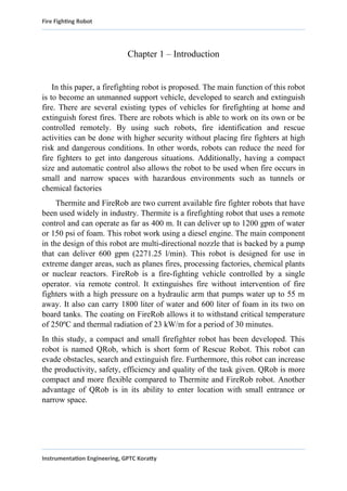
The Flame sensor were installed at front and sides of the robot to detect the
fire respectively. In addition, mini camera was installed in front side of the
robot to monitor the way and condition of the location and is linked to the smart
phone. The structure of fire fighting robot is shown in Fig. 1
Instrumentation Engineering, GPTC Koratty
3.
Fire Fighting Robot
Fig.13D structure of firefighting robot
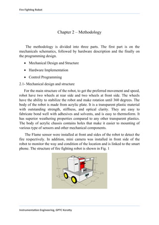
2.2 – Hardware Implementation
The electronic part is one of the vital part in the development of a robot. It
includes sensors, microcontrollers, DC motor with wheel, server motor, motor
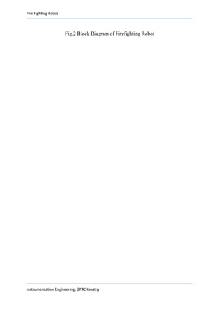
drive and water pump. Fig. 2 shows the block diagram of the firefighting robot
operation which consist of flame sensor as input of the system. Arduino Uno is
used as a microcontroller that is connected with other devices. Motor driver
(L293D) is used to activate moving of the gear motor. Water is pump after the
flame sensor detects flames.
Instrumentation Engineering, GPTC Koratty
4.
Fire Fighting Robot
Fig.2Block Diagram of Firefighting Robot
Instrumentation Engineering, GPTC Koratty
5.
Fire Fighting Robot
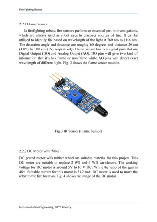
2.2.1Flame Sensor
In firefighting robots, fire sensors perform an essential part in investigations,
which are always used as robot eyes to discover sources of fire. It can be
utilized to identify fire based on wavelength of the light at 760 nm to 1100 nm.
The detection angle and distance are roughly 60 degrees and distance 20 cm
(4.8V) to 100 cm (1V) respectively. Flame sensor has two signal pins that are
Digital Output (DO) and Analog Output (AO). DO pins will give two kind of
information that it’s has flame or non-flame while AO pins will detect exact
wavelength of different light. Fig. 3 shows the flame sensor module.
Fig.3 IR Sensor (Flame Sensor)
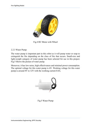
2.2.2 DC Motor with Wheel
DC geared motor with rubber wheel are suitable material for this project. This
DC motor are suitable to replace 2 WD and 4 WD car chassis. The working
voltage for DC motor is around 5V to 10 V DC. While the ratio of the gear is
48:1. Suitable current for this motor is 73.2 mA. DC motor is used to move the
robot to the fire location. Fig. 4 shows the image of the DC motor
Instrumentation Engineering, GPTC Koratty
6.
Fire Fighting Robot
Fig.4DC Motor with Wheel
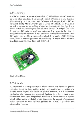
2.2.3 Water Pump
The water pump is important part in this robot as it will pump water or soap to
extinguish the fire depending on the class of fire that occurs. Small-size and
light-weight category of water pump has been selected for use in this project.
Fig.5 Shows the picture of water pump.
Moreover, it has low noise, high effectiveness and minimal power consumption.
The optimal voltage for this water pump is 6V. Working voltage for this water
pump is around 4V to 12V with the working current 0.8A.
Fig.5 Water Pump
Instrumentation Engineering, GPTC Koratty
7.
Fire Fighting Robot
2.2.4Motor Driver
L293D is a typical 16 bit-pin Motor driver IC which allows the DC motor to
drive on either direction. It can control a set of DC motors in any direction
simultaneously i.e. it can control two DC motor with a single IC of L293D by
the dual H-Bridge Motor Driver Integrated Circuit (IC). This IC can drive small
as well as big motors. Its working is based on the concept of H-bridge. It is a
circuit that allows the voltage to flow on either direction. H-bridge IC are ideal
for driving a DC motor, as you know voltage need to change its direction for
being able to rotate the motor in both clockwise anticlockwise directions. Two
DC motors can be able to rotate independently by a single L289D IC. It is
widely used in robotic application for controlling DC motor due to its small
size. Fig.6 show the motor driver with IC L293D
Fig.6 Motor Driver
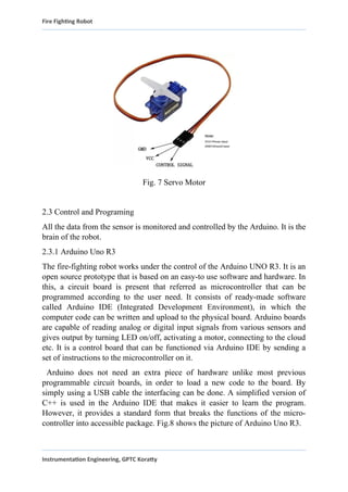
2.2.5 Servo Motor
A servomotor is a rotary actuator or linear actuator that allows for precise
control of angular or linear position, velocity and acceleration. It consists of a
suitable motor coupled to a sensor for position feedback. It is a closed-loop
mechanism that incorporates positional feedback in order to control the
rotational or linear speed and position. The motor is controlled with an electric
signal, either analog or digital, which determines the amount of movement
which represents the final command position for the shaft. Fig.7 shows the
picture of servo motor.
Instrumentation Engineering, GPTC Koratty
8.
Fire Fighting Robot
Fig.7 Servo Motor
2.3 Control and Programing
All the data from the sensor is monitored and controlled by the Arduino. It is the
brain of the robot.
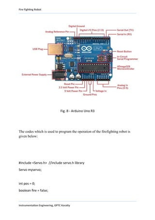
2.3.1 Arduino Uno R3
The fire-fighting robot works under the control of the Arduino UNO R3. It is an
open source prototype that is based on an easy-to use software and hardware. In
this, a circuit board is present that referred as microcontroller that can be
programmed according to the user need. It consists of ready-made software
called Arduino IDE (Integrated Development Environment), in which the
computer code can be written and upload to the physical board. Arduino boards
are capable of reading analog or digital input signals from various sensors and
gives output by turning LED on/off, activating a motor, connecting to the cloud
etc. It is a control board that can be functioned via Arduino IDE by sending a
set of instructions to the microcontroller on it.
Arduino does not need an extra piece of hardware unlike most previous
programmable circuit boards, in order to load a new code to the board. By
simply using a USB cable the interfacing can be done. A simplified version of
C++ is used in the Arduino IDE that makes it easier to learn the program.
However, it provides a standard form that breaks the functions of the micro-
controller into accessible package. Fig.8 shows the picture of Arduino Uno R3.
Instrumentation Engineering, GPTC Koratty
9.
Fire Fighting Robot
Fig.8 - Arduino Uno R3
The codes which is used to program the operation of the firefighting robot is
given below:
#include <Servo.h> //include servo.h library
Servo myservo;
int pos = 0;
boolean fire = false;
Instrumentation Engineering, GPTC Koratty
10.
Fire Fighting Robot
#defineLeft 9 // left sensor
#define Right 10 // right sensor
#define Forward 8 //front sensor
#define LM1 2 // left motor
#define LM2 3 // left motor
#define RM1 4 // right motor
#define RM2 5 // right motor
#define pump 6
void setup()
{
pinMode(Left, INPUT);
pinMode(Right, INPUT);
pinMode(Forward, INPUT);
pinMode(LM1, OUTPUT);
pinMode(LM2, OUTPUT);
pinMode(RM1, OUTPUT);
pinMode(RM2, OUTPUT);
pinMode(pump, OUTPUT);
myservo.attach(11);
myservo.write(90);
}
Instrumentation Engineering, GPTC Koratty
Fire Fighting Robot
elseif (digitalRead(Left) ==0)
{
digitalWrite(LM1, HIGH);
digitalWrite(LM2, LOW);
digitalWrite(RM1, HIGH);
digitalWrite(RM2, HIGH);
}
else if (digitalRead(Right) ==0)
{
digitalWrite(LM1, HIGH);
digitalWrite(LM2, HIGH);
digitalWrite(RM1, HIGH);
digitalWrite(RM2, LOW);
}
delay(300);//change this value to increase the distance
while (fire == true)
{
put_off_fire();
}
}
Instrumentation Engineering, GPTC Koratty
14.
Fire Fighting Robot
Chapter3 – CIRCUIT DIAGRAM
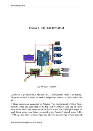
Fig. 9 Circuit Diagram
As shown in given circuit, a Arduino UNO is connected to 18650 li-ion battery.
Negative terminal is connected to Gnd and positive terminal is connected to Vin
pin.
3 flame sensors are connected to Arduino. The Gnd terminal of three flame
sensors sorted and connected to the the Gnd of Arduino. And vcc of flame
sensors are sorted and connected to the 5-volt power pin. And digital output of
each flame sensors are being connected to the Arduino's digital inputs (~10,
~9,8). A servo motor is connected. Gnd of servo is connected to Gnd pin and
Instrumentation Engineering, GPTC Koratty
15.
Fire Fighting Robot
controlsignal terminal is connected to digital pin (~11). And vcc is connected to
the 5-volt power pin. Two L293D motor driver is connected to Arduino. They
are directly connected to power supply and first l293d motor drivers B1, B2
pins are connected to Arduino's 7,5 pins and a water pump is connected at 1MA
2. And the second L293D's A1, A2 pins are connected to digital pins 5,4 of
Arduino. And B1, B2 pins are connected to digital pins ~3,2 of Arduino. And
two dc motors are connected at 2 MB1, 1MA2 PORTS
Chapter 4 – FLOWCHART
Instrumentation Engineering, GPTC Koratty
16.
Fire Fighting Robot
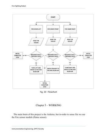
Fig.10 - Flowchart
Chapter 5 – WORKING
The main brain of this project is the Arduino, but in-order to sense fire we use
the Fire sensor module (flame sensor).
Instrumentation Engineering, GPTC Koratty
17.
Fire Fighting Robot
Asyou can see these sensors have an IR Receiver (Photodiode) which is used
to detect the fire. When fire burns it emits a small amount of Infra-red light, this
light will be received by the IR receiver on the sensor module. Then we use an
Op-Amp to check for change in voltage across the IR Receiver, so that if a fire
is detected the output pin (DO) will give 0V(LOW) and if the is no fire the
output pin will be 5V(HIGH). So, we place three such sensors in three
directions of the robot to sense on which direction the fire is burning.
We detect the direction of the fire we can use the motors to move near the fire
by driving our motors through the L293D module. When near a fire we have to
put it out using water. Using a small container, we can carry water, a 5V pump
is also placed in the container and the whole container is placed on top of a
servo motor so that we can control the direction in which the water has to be
sprayed.
Chapter 6 - Application
Can be used in record maintaining rooms where fire can cause lose of
valuable data.
Can be used in sever rooms for the immediate action in the case of fire.
Can be used in extinguishing fire where probability of explosion is high.
Every working environment requiring permanent operator’s attention.
-at power plant control rooms.
-at captain bridges.
-at flight control centers.
Chapter 7 – Future Scope
Instrumentation Engineering, GPTC Koratty
18.
Fire Fighting Robot
Theproject has been motivated by the desire to design a system that can
detect fires and take appropriate action, without any human intervention. The
development of sensor networks and the maturity of robotics suggests that
we can use mobile agents for tasks that involve perception of an
external stimulus and reacting to the stimulus, even when the
reaction involves a significant amount of mechanical actions. This provides
us the opportunity to pass on to robot’s tasks that traditionally humans had to
do but were inherently life-threatening. Fire-fighting is an obvious candidate
for such automation. Given the number of lives lost regularly in fire-fighting,
the system we envision is crying for adoption. Our experience suggests that
designing a fire-fighting system with sensors and robots is within the reach
of the current sensor network and mobile agent technologies. Furthermore,
we believe that the techniques developed in this work will carry over to other
areas involving sensing and reacting to stimulus, where we desire to replace
the human with an automated mobile agent.
Of course, this project has only scratched the surface. As in the design
simplifications and the implementation constraints in suggest, our project is
very much a proof-of-concept. In particular, a practical autonomous fire-
fighting system must include a collection of robots, communicating and
cooperating in the mission; furthermore, such a system requires facilities for
going through obstacles in the presence of fire, and ability to receive
instructions on-the-fly during an operation. All such concerns were outside
the scope of this project. However, there has been research on many of these
pieces in different contexts, e.g., coordination among mobile agents,
techniques for detecting and avoiding obstacles, on-the-fly communication
between humans and mobile agents, etc. It will be both interesting and
challenging to put all this together into a practical, autonomous fire-fighting
service.
Chapter 8 – RESULT
Instrumentation Engineering, GPTC Koratty
19.
Fire Fighting Robot
Firefightingrobot has been developed to find the location of fire and
extinguish it. It has an ability to find the location by using flame sensor. The
flame sensor is functioning to sense the location of fire around the robot. the
sensors are connected to Arduino Uno, which controlled the movement of DC
motor.
When flame sensor found the fire, the DC motor will stop at 10 cm from the
fire. The robot will be extinguishing the fire using water pump.
Chapter 9 – CONCLUSION
Overall, a fire-fighting robot that can work automatically has been successfully
developed. It has advantageous features such as ability to detect location of fire
automatically besides having a compact body and lightweight structure. This
robot can be used at a place that has a small entrance or in small spaces because
it has a compact structure. From the experimental results, the robot can sense
smokes and fire accurately in a short time. As a conclusion, the project entitled
“Fire Fighting Robot” has achieved its aim and objective successfully.
Instrumentation Engineering, GPTC Koratty
![Fire Fighting Robot
References
[1] Mr. Harsh Jain, “video presentation on QRobo”
Instrumentation Engineering, GPTC Koratty](https://image.slidesharecdn.com/519209623-fire-fighting-robot-mini-project1-250613190938-73ff67f0/85/519209623-FIRE-FIGHTING-ROBOT-mini-project-1-pdf-20-320.jpg)
![Fire Fighting Robot
[2]
Instrumentation Engineering, GPTC Koratty](https://image.slidesharecdn.com/519209623-fire-fighting-robot-mini-project1-250613190938-73ff67f0/85/519209623-FIRE-FIGHTING-ROBOT-mini-project-1-pdf-21-320.jpg)