The document discusses the design methodology for slender reinforced concrete columns based on Eurocode 2 (EC2), highlighting the significance of slenderness effects on structural performance. It defines slender columns, differentiating them from short columns, and outlines the impact of lateral deformations and bending moments on their load-carrying capacity. Additionally, the paper presents equations and design approaches for calculating design moments, emphasizing the need for considering second-order effects in slender columns.
![2nd
International Balkans Conference on Challenges of Civil Engineering, BCCCE, 23-25 May 2013, Epoka University, Tirana, Albania.
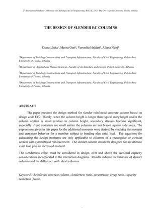
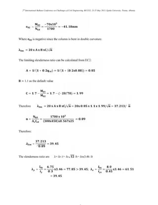
Fig. 2
The accidental eccentricity ei is given by the equation:
= ν (3.4)
l0 is the effective column height about the axis considered, which depends on the length l, and
on the boundary conditions of the column.
=
√
>
L IS THE HEIGHT OF THE COLUMN IN METERS. A CONSERVATIVE ESTIMATE
OF CAN BE GIVEN BY:
= = =
The nominal second order moment M2 = NEd e2
The second order eccentricity or the deflection e2 is calculated as:
e2= 0 [ ∗
⁄ ] = 0 [ ² ∗
⁄ ]= 0 [10 ∗
⁄ ] (3.5)
= ² ≈ 10 is a factor depending on the curvature distribution,](https://image.slidesharecdn.com/shortslendercolumns-240528120612-515e7efc/85/description-and-difference-between-short-slender-columns-5-320.jpg)
![2nd
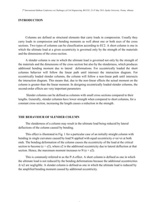
International Balkans Conference on Challenges of Civil Engineering, BCCCE, 23-25 May 2013, Epoka University, Tirana, Albania.
1/r is the curvature: = ∗ ∗ (3.6)
The basic value of the curvature is:
=
/
. ∗
= .
(3.7)
Es is the elastic modulus of steel, d = (h/2) + is and is is the radius of gyration of the total
reinforcement area.
The second-order eccentricity is an estimate of the deflection of the column at failure and is
given by the equation:
e2=
∗ ∗ ∗
. ²
(3.8)
Kr is a correction factor depending on axial load
Kr = (nu - n) / (nu - nbal) ≤ 1 (3.9)
n = NEd / (Ac fcd) is the relative axial force; NEd is the design value of axial force
nu = 1 + ω, where ω = As fyd / (Ac fcd)
nbal is the value of n at maximum moment resistance; the value 0,4 may be used (EC2)
Ac is the gross area of the concrete section
As is the area of longitudinal reinforcement
Kr=[1+ - ]/[1+ -0.4]≤1 (3.10)](https://image.slidesharecdn.com/shortslendercolumns-240528120612-515e7efc/85/description-and-difference-between-short-slender-columns-6-320.jpg)
![2nd
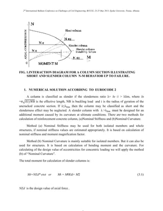
International Balkans Conference on Challenges of Civil Engineering, BCCCE, 23-25 May 2013, Epoka University, Tirana, Albania.
The column is slender and is critical.
Equivalent eccentricity = . + . ≥ .
. + . = . . + . (− . ) =
. = . . = .
The equivalent eccentricity =
The accidental eccentricity is: = ⁄ = ⁄ = .
The second-order eccentricity is
=
where : = { + . + − ; }
= { + . + − . . = . ; }
= [ ] [ ]
⁄ = [ ] [
⁄ ]
= .
with = 1.0 for the initial value.
For the first iteration the total eccentricity is
= + + = + . + . = .](https://image.slidesharecdn.com/shortslendercolumns-240528120612-515e7efc/85/description-and-difference-between-short-slender-columns-12-320.jpg)
![2nd
International Balkans Conference on Challenges of Civil Engineering, BCCCE, 23-25 May 2013, Epoka University, Tirana, Albania.
CONCLUSION
A slender column must be design for an additional moment caused by its curvature at
ultimate condition. The expressions given in EC2 for the additional moments were derived by
studying the moment/curvature behavior for a member subject to bending plus axial load. The
equations for calculating the design moments are only applicable to columns of a rectangular or
circular section with symmetrical reinforcement.
There are four different approaches to designing slender columns accoding to EC2:
A general method based on a non-linear analysis of the structure and allowing for second-
order effects that necessitates the use of computer analysis.
A second-order analysis based on nominal stiffness values of the beams and columns
requires computer analysis using a process of iterative analysis.
The method of Nominal Stiffness may be used for both isolated members and whole
structures. It is based on calculation of nominal stiffness and moment magnification factor.
The method of Nominal Curvature is mainly suitable for isolated members but it can also
be used for whole structures. It is based on calculation of bending moment and the curvature.
These second-order moments are added to the first-order moments to give the total column
design moment.
3. REFERENCES
[1] Eurocode 2 (2004), „Design of concrete structures – Part 1-1: General rules and rules for
buildings”, EN 1992-1-1.
[2] Design of Concrete Structures, A. Nilson, D. Darwin, Ch. Dolan, New York, NY (2010).
[3] ACI 318-08, Building Code Requirements for Structural Concrete and Commentary, (2007).
[4] Design of Reinforcement Concrete, J.C.McComac, J.K.Nelson. Seventh Edition, (2004),
USA.
[5] Nonlinear Mechanics of Reinforcement Concrete, Makeawa, Pimanmas and Okamura, Spon
Press, London and New York (2003).](https://image.slidesharecdn.com/shortslendercolumns-240528120612-515e7efc/85/description-and-difference-between-short-slender-columns-16-320.jpg)


