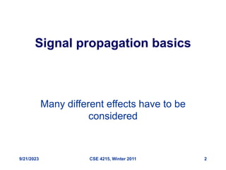
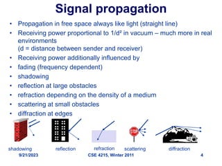
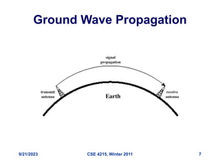
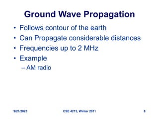
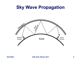
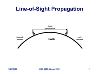
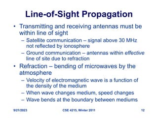
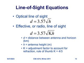
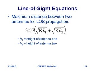
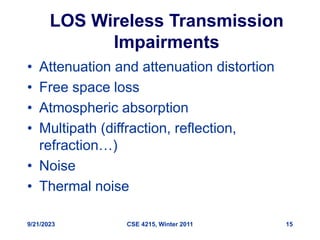
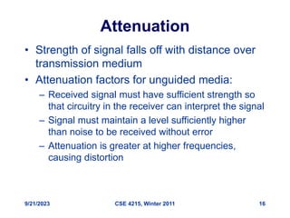
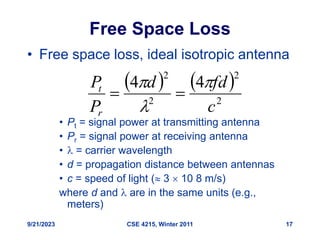
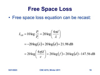
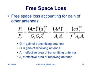
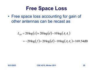
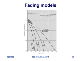
9/21/2023 CSE 4215, Winter 2011 1
CSE 4215/5431:
Mobile Communications
Winter 2011
Suprakash Datta
datta@cs.yorku.ca
Office: CSEB 3043
Phone: 416-736-2100 ext 77875
Course page: http://www.cs.yorku.ca/course/4215
Some slides are adapted from the book website
9/21/2023 CSE 4215, Winter 2011 2
Signal propagation basics
Many different effects have to be
considered
9/21/2023 CSE 4215, Winter 2011 3
Signal propagation ranges
• Transmission range
– communication possible
– low error rate
• Detection range
– detection of the signal
possible
– no communication
possible
• Interference range
– signal may not be
detected
– signal adds to the
background noise
distance
sender
transmission
detection
interference
9/21/2023 CSE 4215, Winter 2011 4
Signal propagation
• Propagation in free space always like light (straight line)
• Receiving power proportional to 1/d² in vacuum – much more in real
environments
(d = distance between sender and receiver)
• Receiving power additionally influenced by
• fading (frequency dependent)
• shadowing
• reflection at large obstacles
• refraction depending on the density of a medium
• scattering at small obstacles
• diffraction at edges
reflection scattering diffraction
shadowing refraction
9/21/2023 CSE 4215, Winter 2011 5
Real world example
9/21/2023 CSE 4215, Winter 2011 6
Propagation Modes
• Ground-wave propagation
• Sky-wave propagation
• Line-of-sight propagation
9/21/2023 CSE 4215, Winter 2011 7
Ground Wave Propagation
9/21/2023 CSE 4215, Winter 2011 8
Ground Wave Propagation
• Follows contour of the earth
• Can Propagate considerable distances
• Frequencies up to 2 MHz
• Example
– AM radio
9/21/2023 CSE 4215, Winter 2011 9
Sky Wave Propagation
9/21/2023 CSE 4215, Winter 2011 10
Sky Wave Propagation
• Signal reflected from ionized layer of
atmosphere back down to earth
• Signal can travel a number of hops,
back and forth between ionosphere and
earth’s surface
• Reflection effect caused by refraction
• Examples
– Amateur radio
– CB radio
9/21/2023 CSE 4215, Winter 2011 11
Line-of-Sight Propagation
9/21/2023 CSE 4215, Winter 2011 12
Line-of-Sight Propagation
• Transmitting and receiving antennas must be
within line of sight
– Satellite communication – signal above 30 MHz
not reflected by ionosphere
– Ground communication – antennas within effective
line of site due to refraction
• Refraction – bending of microwaves by the
atmosphere
– Velocity of electromagnetic wave is a function of
the density of the medium
– When wave changes medium, speed changes
– Wave bends at the boundary between mediums
9/21/2023 CSE 4215, Winter 2011 13
Line-of-Sight Equations
• Optical line of sight
• Effective, or radio, line of sight
• d = distance between antenna and horizon
(km)
• h = antenna height (m)
• K = adjustment factor to account for
refraction, rule of thumb K = 4/3
h
d 57
.
3

h
d 
 57
.
3
9/21/2023 CSE 4215, Winter 2011 14
Line-of-Sight Equations
• Maximum distance between two
antennas for LOS propagation:
• h1 = height of antenna one
• h2 = height of antenna two
 
2
1
57
.
3 h
h 


9/21/2023 CSE 4215, Winter 2011 15
LOS Wireless Transmission
Impairments
• Attenuation and attenuation distortion
• Free space loss
• Atmospheric absorption
• Multipath (diffraction, reflection,
refraction…)
• Noise
• Thermal noise
9/21/2023 CSE 4215, Winter 2011 16
Attenuation
• Strength of signal falls off with distance over
transmission medium
• Attenuation factors for unguided media:
– Received signal must have sufficient strength so
that circuitry in the receiver can interpret the signal
– Signal must maintain a level sufficiently higher
than noise to be received without error
– Attenuation is greater at higher frequencies,
causing distortion
9/21/2023 CSE 4215, Winter 2011 17
Free Space Loss
• Free space loss, ideal isotropic antenna
• Pt = signal power at transmitting antenna
• Pr = signal power at receiving antenna
•  = carrier wavelength
• d = propagation distance between antennas
• c = speed of light ( 3  10 8 m/s)
where d and  are in the same units (e.g.,
meters)
   
2
2
2
2
4
4
c
fd
d
P
P
r
t 




9/21/2023 CSE 4215, Winter 2011 18
Free Space Loss
• Free space loss equation can be recast:









d
P
P
L
r
t
dB
4
log
20
log
10
    dB
98
.
21
log
20
log
20 


 d

    dB
56
.
147
log
20
log
20
4
log
20 








 d
f
c
fd

9/21/2023 CSE 4215, Winter 2011 19
Free Space Loss
• Free space loss accounting for gain of
other antennas
• Gt = gain of transmitting antenna
• Gr = gain of receiving antenna
• At = effective area of transmitting antenna
• Ar = effective area of receiving antenna
       
t
r
t
r
t
r
r
t
A
A
f
cd
A
A
d
G
G
d
P
P
2
2
2
2
2
2
4






9/21/2023 CSE 4215, Winter 2011 20
Free Space Loss
• Free space loss accounting for gain of
other antennas can be recast as
     
r
t
dB A
A
d
L log
10
log
20
log
20 

 
      dB
54
.
169
log
10
log
20
log
20 



 r
t A
A
d
f
Multipath Propagation
9/21/2023 CSE 4215, Winter 2011 22
Multipath propagation
• Signal can take many different paths between sender
and receiver due to reflection, scattering, diffraction
• Time dispersion: signal is dispersed over time
– interference with “neighbor” symbols, Inter Symbol
Interference (ISI)
• The signal reaches a receiver directly and phase
shifted
– distorted signal depending on the phases of the different
parts
signal at sender
signal at receiver
LOS pulses
multipath
pulses
9/21/2023 CSE 4215, Winter 2011 23
Atmospheric absorption
• Water vapor and oxygen contribute
most
• Water vapor: peak attenuation near
22GHz, low below 15Ghz
• Oxygen: absorption peak near 60GHz,
lower below 30 GHz.
• Rain and fog may scatter (thus
attenuate) radio waves.
• Low frequency band usage helps…
9/21/2023 CSE 4215, Winter 2011 24
Effects of mobility
• Channel characteristics change over time and
location
– signal paths change
– different delay variations of different signal parts
– different phases of signal parts
–  quick changes in the power received (short term
fading)
• Additional changes in
– distance to sender
– obstacles further away
–  slow changes in the average
power received (long term fading)
short term fading
long term
fading
t
power
9/21/2023 CSE 4215, Winter 2011 25
Fading channels
• Fading: Time variation of received
signal power
• Mobility makes the problem of modeling
fading difficult
• Multipath propagation is a key reason
• Most challenging technical problem for
Mobile Communications
9/21/2023 CSE 4215, Winter 2011 26
Types of Fading
• Short term (fast) fading
• Long term (slow) fading
• Flat fading – across all frequencies
• Selective fading – only in some frequencies
• Rayleigh fading – no LOS path, many other
paths
• Rician fading – LOS path plus many other
paths
9/21/2023 CSE 4215, Winter 2011 27
Fading models
9/21/2023 CSE 4215, Winter 2011 28
Dealing with fading channels
• Error correction
• Adaptive equalization
– attempts to increase signal power as needed
– can be done with analog circuits or DSP

4215L3-Signal propagation basics

  • 1.
    9/21/2023 CSE 4215,Winter 2011 1 CSE 4215/5431: Mobile Communications Winter 2011 Suprakash Datta datta@cs.yorku.ca Office: CSEB 3043 Phone: 416-736-2100 ext 77875 Course page: http://www.cs.yorku.ca/course/4215 Some slides are adapted from the book website
  • 2.
    9/21/2023 CSE 4215,Winter 2011 2 Signal propagation basics Many different effects have to be considered
  • 3.
    9/21/2023 CSE 4215,Winter 2011 3 Signal propagation ranges • Transmission range – communication possible – low error rate • Detection range – detection of the signal possible – no communication possible • Interference range – signal may not be detected – signal adds to the background noise distance sender transmission detection interference
  • 4.
    9/21/2023 CSE 4215,Winter 2011 4 Signal propagation • Propagation in free space always like light (straight line) • Receiving power proportional to 1/d² in vacuum – much more in real environments (d = distance between sender and receiver) • Receiving power additionally influenced by • fading (frequency dependent) • shadowing • reflection at large obstacles • refraction depending on the density of a medium • scattering at small obstacles • diffraction at edges reflection scattering diffraction shadowing refraction
  • 5.
    9/21/2023 CSE 4215,Winter 2011 5 Real world example
  • 6.
    9/21/2023 CSE 4215,Winter 2011 6 Propagation Modes • Ground-wave propagation • Sky-wave propagation • Line-of-sight propagation
  • 7.
    9/21/2023 CSE 4215,Winter 2011 7 Ground Wave Propagation
  • 8.
    9/21/2023 CSE 4215,Winter 2011 8 Ground Wave Propagation • Follows contour of the earth • Can Propagate considerable distances • Frequencies up to 2 MHz • Example – AM radio
  • 9.
    9/21/2023 CSE 4215,Winter 2011 9 Sky Wave Propagation
  • 10.
    9/21/2023 CSE 4215,Winter 2011 10 Sky Wave Propagation • Signal reflected from ionized layer of atmosphere back down to earth • Signal can travel a number of hops, back and forth between ionosphere and earth’s surface • Reflection effect caused by refraction • Examples – Amateur radio – CB radio
  • 11.
    9/21/2023 CSE 4215,Winter 2011 11 Line-of-Sight Propagation
  • 12.
    9/21/2023 CSE 4215,Winter 2011 12 Line-of-Sight Propagation • Transmitting and receiving antennas must be within line of sight – Satellite communication – signal above 30 MHz not reflected by ionosphere – Ground communication – antennas within effective line of site due to refraction • Refraction – bending of microwaves by the atmosphere – Velocity of electromagnetic wave is a function of the density of the medium – When wave changes medium, speed changes – Wave bends at the boundary between mediums
  • 13.
    9/21/2023 CSE 4215,Winter 2011 13 Line-of-Sight Equations • Optical line of sight • Effective, or radio, line of sight • d = distance between antenna and horizon (km) • h = antenna height (m) • K = adjustment factor to account for refraction, rule of thumb K = 4/3 h d 57 . 3  h d   57 . 3
  • 14.
    9/21/2023 CSE 4215,Winter 2011 14 Line-of-Sight Equations • Maximum distance between two antennas for LOS propagation: • h1 = height of antenna one • h2 = height of antenna two   2 1 57 . 3 h h   
  • 15.
    9/21/2023 CSE 4215,Winter 2011 15 LOS Wireless Transmission Impairments • Attenuation and attenuation distortion • Free space loss • Atmospheric absorption • Multipath (diffraction, reflection, refraction…) • Noise • Thermal noise
  • 16.
    9/21/2023 CSE 4215,Winter 2011 16 Attenuation • Strength of signal falls off with distance over transmission medium • Attenuation factors for unguided media: – Received signal must have sufficient strength so that circuitry in the receiver can interpret the signal – Signal must maintain a level sufficiently higher than noise to be received without error – Attenuation is greater at higher frequencies, causing distortion
  • 17.
    9/21/2023 CSE 4215,Winter 2011 17 Free Space Loss • Free space loss, ideal isotropic antenna • Pt = signal power at transmitting antenna • Pr = signal power at receiving antenna •  = carrier wavelength • d = propagation distance between antennas • c = speed of light ( 3  10 8 m/s) where d and  are in the same units (e.g., meters)     2 2 2 2 4 4 c fd d P P r t     
  • 18.
    9/21/2023 CSE 4215,Winter 2011 18 Free Space Loss • Free space loss equation can be recast:          d P P L r t dB 4 log 20 log 10     dB 98 . 21 log 20 log 20     d      dB 56 . 147 log 20 log 20 4 log 20           d f c fd 
  • 19.
    9/21/2023 CSE 4215,Winter 2011 19 Free Space Loss • Free space loss accounting for gain of other antennas • Gt = gain of transmitting antenna • Gr = gain of receiving antenna • At = effective area of transmitting antenna • Ar = effective area of receiving antenna         t r t r t r r t A A f cd A A d G G d P P 2 2 2 2 2 2 4      
  • 20.
    9/21/2023 CSE 4215,Winter 2011 20 Free Space Loss • Free space loss accounting for gain of other antennas can be recast as       r t dB A A d L log 10 log 20 log 20           dB 54 . 169 log 10 log 20 log 20      r t A A d f
  • 21.
  • 22.
    9/21/2023 CSE 4215,Winter 2011 22 Multipath propagation • Signal can take many different paths between sender and receiver due to reflection, scattering, diffraction • Time dispersion: signal is dispersed over time – interference with “neighbor” symbols, Inter Symbol Interference (ISI) • The signal reaches a receiver directly and phase shifted – distorted signal depending on the phases of the different parts signal at sender signal at receiver LOS pulses multipath pulses
  • 23.
    9/21/2023 CSE 4215,Winter 2011 23 Atmospheric absorption • Water vapor and oxygen contribute most • Water vapor: peak attenuation near 22GHz, low below 15Ghz • Oxygen: absorption peak near 60GHz, lower below 30 GHz. • Rain and fog may scatter (thus attenuate) radio waves. • Low frequency band usage helps…
  • 24.
    9/21/2023 CSE 4215,Winter 2011 24 Effects of mobility • Channel characteristics change over time and location – signal paths change – different delay variations of different signal parts – different phases of signal parts –  quick changes in the power received (short term fading) • Additional changes in – distance to sender – obstacles further away –  slow changes in the average power received (long term fading) short term fading long term fading t power
  • 25.
    9/21/2023 CSE 4215,Winter 2011 25 Fading channels • Fading: Time variation of received signal power • Mobility makes the problem of modeling fading difficult • Multipath propagation is a key reason • Most challenging technical problem for Mobile Communications
  • 26.
    9/21/2023 CSE 4215,Winter 2011 26 Types of Fading • Short term (fast) fading • Long term (slow) fading • Flat fading – across all frequencies • Selective fading – only in some frequencies • Rayleigh fading – no LOS path, many other paths • Rician fading – LOS path plus many other paths
  • 27.
    9/21/2023 CSE 4215,Winter 2011 27 Fading models
  • 28.
    9/21/2023 CSE 4215,Winter 2011 28 Dealing with fading channels • Error correction • Adaptive equalization – attempts to increase signal power as needed – can be done with analog circuits or DSP