
Recommended
More Related Content
Similar to 3439.full
Similar to 3439.full (20)
Recently uploaded
Recently uploaded (20)
3439.full
- 1. The first appearance of winged insects is shrouded in the past, but they probably took to the air almost 350 million years ago (Wootton, 1981; Ellington, 1991a). Wingspans of the early fossils ranged from 10 to 710 mm, and the form of the wings suggests a variety of adaptations in flight style. The Protodonata, which were the ancestors of dragonflies, were among the early fliers; their wings were similar enough to modern forms to suggest comparable flight capabilities, although perhaps with less refinement. Through natural selection, the insects have been experimenting successfully with wings, kinematics, aerodynamics, control and sensory systems for hundreds of millions of years. Much more recently, interest has developed in small autonomous flying vehicles, largely motived by the need for aerial reconnaissance robots inside buildings and confined spaces. Industry, commerce and the military have all identified potential roles for such micro-air vehicles (MAVs). Research on MAVs is primarily conducted by aerodynamic and robotic engineers who are attempting to improve the performance at small sizes of conventional fixed wings and rotary wings. However, there already exists a very successful design for intelligent MAVs with much better aerodynamic performance than conventional wings and rotors: the insects. When contemplating the design of small flying machines, therefore, we would be well advised to consider them. There are some general, simplifying trends in insect evolution. For example, early insects had two pairs of wings, but most modern forms have either lost one pair or coupled the fore- and hindwings together into a single functional pair. This simplification is in stark contrast to the elaborate and idiosyncratic wing designs found in some insects: e.g. wing ornamentation and special motions for courtship and mating displays; thickening of the forewings into hard protective shells; modification of the hindwings of flies into distinctive sensory organs, the halteres. Such aerodynamic oddities are of little interest here. Small flying machines are in their infancy, and the purpose of this paper is to identify general- purpose designs that have survived the testbed of insect evolution. Furthermore, these designs should be reduced to their simplest features, such as only one pair of wings. Scaling The smallest flying insects that have been studied weigh 20–30µg and the largest approximately 2–3 g. Over this 100000-fold size range, the design is very close to isometric: wing area is proportional to m2/3 on average, where m is body mass. Wingbeat frequency increases as size decreases, scaling as m−1/4 (Dudley, 2000). There is very considerable scatter in such scaling relationships; individual species can compensate for a relatively small wing area, for example, by a higher 3439The Journal of Experimental Biology 202, 3439–3448 (1999) Printed in Great Britain © The Company of Biologists Limited 1999 JEB2214 The wing motion in free flight has been described for insects ranging from 1 to 100mm in wingspan. To support the body weight, the wings typically produce 2–3 times more lift than can be accounted for by conventional aerodynamics. Some insects use the fling mechanism: the wings are clapped together and then flung open before the start of the downstroke, creating a lift-enhancing vortex around each wing. Most insects, however, rely on a leading- edge vortex (LEV) created by dynamic stall during flapping; a strong spanwise flow is also generated by the pressure gradients on the flapping wing, causing the LEV to spiral out to the wingtip. Technical applications of the fling are limited by the mechanical damage that accompanies repeated clapping of the wings, but the spiral LEV can be used to augment the lift production of propellers, rotors and micro-air vehicles (MAVs). Design characteristics of insect-based flying machines are presented, along with estimates of the mass supported, the mechanical power requirement and maximum flight speeds over a wide range of sizes and frequencies. To support a given mass, larger machines need less power, but smaller ones operating at higher frequencies will reach faster speeds. Key words: insect, flight, aerodynamics, flapping flight, micro-air vehicle. Summary Introduction THE NOVEL AERODYNAMICS OF INSECT FLIGHT: APPLICATIONS TO MICRO-AIR VEHICLES C. P. ELLINGTON* Department of Zoology, University of Cambridge, Downing Street, Cambridge CB2 3EJ, UK *e-mail: c.ellington@zoo.cam.ac.uk Accepted 15 September; published on WWW 16 November 1999
- 2. 3440 wingbeat frequency. However, the general trends confirm that the insects do follow a basic pattern. The aerodynamics of insect flight is affected by the scaling of the Reynolds number Re, which is the ratio of inertial to viscous forces in a fluid. Re is defined as the product of a characteristic length and velocity divided by the kinematic viscosity ν of the fluid. For comparative purposes, we can conveniently ignore the forward velocity and define a mean Re for hovering flight based on the mean chord c¯ (=2R/AR) and the mean wingtip velocity U – t (=2ΦnR): where AR is the aspect ratio, n is the wingbeat frequency, R is the wing length and Φ is the wingbeat amplitude (peak-to- peak, in rad). Given geometric similarity and the scaling of frequency, Re increases as m0.42. For large insects, Re lies between 5000 and 10000, but it approaches 10 for the smallest ones. In all cases, the airflow is in the laminar regime, but viscous effects become progressively more important as size decreases. Kinematics of ‘normal’ insect flight The wing motion in free flight has been described for insects with wingspans from approximately 1 to 100 mm, covering the wide range of Re discussed above. Most of the wing motions are rather similar and constitute a picture of ‘normal’ flight that is probably a good starting point for the design of insect-based flying machines. Other wing motions offer special advantages that might prove useful for some purposes. In general, the flapping motion is approximately confined to a ‘stroke plane’, which is at a nearly constant orientation with respect to the body for most insects. Studies on bumblebees offer one of the most complete kinematic descriptions of free flight (Dudley and Ellington, 1990a,b; Cooper, 1993) and will be used to illustrate the main points of this section. Bumblebees vary considerably in size; I shall refer to an individual with a mass of 0.175g, a wing length R of 13.2mm, a wingbeat frequency n of 149Hz and a wingbeat amplitude Φ of 114°. Recent work on the large hawkmoth Manduca sexta provides an interesting comparison (Willmott and Ellington, 1997a,b); the individuals were more uniform in size, with masses of 1.6–2.0 g, R=51mm, N=25–26Hz and Φ ranging from approximately 115–120 ° during hovering to 100–105 ° at top speeds. Although much larger, the hawkmoth has disproportionately longer wings and hence a lower wing loading: 9 Nm−2 compared with 36 Nm−2 for bumblebee queens. Both species use what might be called ‘normal’ flight. Wingtip paths Fig. 1 shows the path of the wing tip through the air for a bumblebee worker hovering and at speeds up to 4.5ms−1, which is close to the maximum flight speed of 5–6ms−1. The wingtip path would look much the same for an insect with twice the flapping velocity flying twice as fast, so it is more useful for comparative purposes to introduce a dimensionless measure of speed: the flight velocity divided by the flapping velocity. By analogy to propeller theory, we call this the advance ratio J. The flapping velocity varies linearly along the wing, and some representative value must be chosen to calculate an advance ratio. Again, we choose the mean wingtip flapping velocity, and the advance ratio J is then: where V is the flight velocity. The advance ratio is zero during hovering and rises to approximately 0.6 for bumblebees at high speed. It may be useful to think of J as the forward speed in wing lengths per wingbeat (=V/nR) divided by 2Φ. The wingtip path is determined by the vector sum of the flight, flapping and downwash velocities; the all-important velocity of the wing relative to the air is given by the tangent to the path. Lift and drag are therefore perpendicular and parallel to the path, respectively, and the resultant force vectors are drawn to scale for each half-stroke in Fig. 1. During hovering, the stroke plane is horizontal, and the wingtip path is determined only by the flapping velocity and the downwash. The downstroke and upstroke are nearly symmetrical, providing weight support but no net horizontal thrust. The wing rotates through approximately 120° between the half- strokes, so the leading edge always leads, and the anatomical lower surface of the wing becomes the aerodynamic upper surface on the upstroke. In effect, the wing oscillates between positive and negative angles of attack, 90° out of phase with the flapping motion. As flight speed and advance ratio increase, the body tilts nose-down, and finally becomes horizontal; body drag is therefore minimised at high speeds, where it is increasingly important. The stroke plane rotates with the body orientation and eventually reaches an inclination of approximately 40 ° to the horizontal. As advance ratio increases, the downstroke increasingly dominates the force balance; the downstroke path becomes relatively longer, indicating a higher velocity and thus larger forces. At high J, the asymmetry is very pronounced, with the powerful downstroke responsible for weight support and some thrust, but the direction of the feeble upstroke force is suitable for thrust only. The required thrust is never very large for insect flight, and even at high speeds it is only some 10–20% of the weight. The net aerodynamic force is therefore nearly vertical, tilted forwards by less than approximately 10°. Between hovering and fast flight, the stroke plane tilts by almost 40° for the bumblebee, but the net force vector tilts by only 8°. The geometry of the wingtip path is of paramount importance; it fixes the direction and relative magnitude of the wing forces on the downstroke and upstroke. This geometry is determined mainly by the advance ratio, then by the stroke plane angle, and finally to a small extent by the relative (2)J = , V 2ΦnR (1)Re = = , c¯U – t ν 4ΦnR2 νAR C. P. ELLINGTON
- 3. 3441Insect flight and micro-air vehicles magnitude of the downwash. The advance ratio fixes both the relative wavelength of the wingpath (=V/nR) and, through Φ, its baseline amplitude. The stroke plane angle then controls the symmetry of the half-strokes and the inclination of their respective paths. Fig. 1 shows clearly that, as advance ratio increases, the tilt of the stroke plane ensures that the inclination of the downstroke path changes but little over the forward speed range. For a given downstroke lift-to-drag ratio, which will presumably be at some optimal value, the stroke plane angle must be such that the inclination of the downstroke path produces the almost vertical net aerodynamic force. At lower advance ratios, the geometry is not so constrained and the downstroke path can be somewhat less inclined, because the increasing upstroke forces will cancel the slightly backwards direction of the downstroke forces. Maximum flight speeds seem to be reached at the advance ratio and stroke plane angle combination giving a nearly vertical upstroke path and a downstroke path inclination consistent with the lift-to-drag ratio. For bumblebees over a large size range (Dudley and Ellington, 1990a; Cooper, 1993) and for hawkmoths (Willmott and Ellington, 1997b), this corresponds to J around 0.6–0.9. Hawkmoths seem able to exceed this limit slightly by not reversing the angle of attack on the upstroke at the highest speeds. The upstroke therefore provides some weight support but a negative thrust, and the insect struggles to produce a net positive thrust over the cycle. This is a highly unusual kinematic adaptation, however, and needs further study. Advance ratios in excess of 1 have also been reported for some butterflies and a day-flying moth (Betts and Wootton, 1988; Dudley, 1990; Dudley and DeVries, 1990). It is not yet known whether these slightly higher values are correlated with their low aspect-ratio wings and low wingbeat frequencies. An upper limit to the advance ratio of around unity determines the maximum flight speed for a given flapping velocity. Dreams of very high speed insect-based micro-air vehicles (MAVs) will simply not be realised; top speeds are limited by the advance ratio, just as with propellers. Kinematic changes with speed The most obvious kinematic changes with increasing speed can be seen with the naked eye: the concomitant tilting of the body and stroke plane. The relationship is approximately linear with speed. At top speed, the body is close to horizontal, and the stroke plane angle reaches approximately 40 ° for the bumblebee and 50–60 ° for the hawkmoth. For both insects, the wingbeat frequency is rather constant, although with large sample sizes Cooper (1993) found a shallow U-shaped relationship between wingbeat frequency and speed for bumblebees. Wingbeat amplitude Φ tends to decrease with speed: by 20–30° for bumblebees (Cooper, 1993) and by approximately 15° for hawkmoths (Willmott and Ellington, 1997a). Results for other insects either support this trend or else suggest that amplitude remains constant. Bumblebees and the hawkmoth are the only insects in which angle of attack has been measured over the entire speed range. It has already been stated that the angle is reversed on the downstroke and upstroke, except for the hawkmoth at the highest speeds. The geometric angle of attack α relative to the stroke plane varies with speed, with the end result that the effective angle of attack αr relative to the wingtip path remains fairly constant at around 30° during most of the downstroke. The negative αr on the upstroke is of similar magnitude for the bumblebee, but smaller for the hawkmoth. It would be reasonable to assume that the changes in geometrical angle of attack, particularly on the more important downstroke, ensure that the wings are always operating close to some optimal angle relative to the airflow. At 30 °, αr seems very high compared with that of conventional wings, but it is quite characteristic of insect wings at their lower Re. The wings are also twisted by 10–20 ° along their length, rather like propellers, with a higher angle of attack at the wing base than at the tip. Fruit-fly wings, however, show a negligible twist; these small wings appear relatively stiffer than those of larger insects and hence more resistant to torsional twisting (Vogel, 1967; Weis-Fogh, 1972; Ellington, 1984b). Hover J=0 1ms-1 J=0.13 2.5ms-1 J=0.32 4.5ms-1 J=0.58 Fig. 1. A two-dimensional view of the wingtip path for a bumblebee Bombus terrestris at different flight speeds. Resultant aerodynamic forces are shown for representative downstrokes and upstrokes. The anatomical lower wing surface is marked by a triangle at the leading edge. Wingbeat frequency and stroke amplitude did not vary significantly with speed, and values of the advance ratio J are calculated using their means. Adapted from Ellington (1995).
- 4. 3442 Control and stability Many insects are capable of remarkable controlled manoeuvres. High-speed films of them flying slowly inside chambers sometimes reveal horizontal thrusts up to five times their weight (Ellington, 1984b). More gentle manoeuvres, however, are simply controlled by tilting the stroke plane, as for a helicopter. Horizontal changes in flight direction and velocity are always preceded by a tilt of the stroke plane: the tilt is increased as the insects accelerate forward, and decreased, usually becoming negative, as they decelerate or begin backward flight. Similarly, accelerations in lateral directions are accompanied by a roll of the stroke plane. Roll can be effected by increasing the flapping amplitude and/or angle of attack of the outside wing. Pitching results from a fore/aft shift of the centre of lift, which pitches the body and hence the stroke plane. The shift can be realised by changing the fore/aft extent of the flapping motion and/or the angle of attack over a half-stroke. Studies on bumblebees and the hawkmoth suggest that a backward shift of the flapping motion is partly responsible for the increasing tilt of the stroke plane with forward speed (Dudley and Ellington, 1990b; Willmott and Ellington, 1997a). A nose-down pitching moment from body lift, which is typically less than 10 % of the weight and thus a small component in the force balance, also contributes significantly to the body and stroke plane inclination at forward speeds. Changes in angle of attack have been observed to initiate accelerations at low speeds (Ellington, 1984b). To accelerate into forward or backward flight, insects increase the angle of attack to large values on the upstroke or downstroke, respectively, and use the increased drag to initiate acceleration. The angle of attack on the drag-producing half-stroke often approaches 90 ° and provides large horizontal accelerations. This ‘paddling’ or ‘rowing’ motion also rotates the body (and the stroke plane) in the correct direction because the drag force is applied above the centre of mass. As the stroke plane tilts, the increased drag would detract from weight support, and the insects revert to more normal angles of attack after only one or two wingbeats. During hovering and slow flight, the body hangs below the wing bases, and the insect benefits from passive pendulum stability. The centre of mass typically lies close to the junction between the thorax and abdomen, and this will produce a nose- up pitching moment even at the large body angles observed for slow flight. The wings must therefore produce a compensatory nose-down pitching moment about their bases, and this is accomplished by locating the centre of lift aft of the body; the mean flapping angle of the wings in the stroke plane is typically directed 20–30 ° backwards during hovering (Ellington, 1984b). Thus, the insects can control the mean pitching moment, and hence the mean body angle, simply by changing the mean flapping angle of the wings. Whether passive pendulum stability applies to faster flight speeds has not been addressed. I suspect that the flight becomes unstable to some extent, but it is difficult to investigate experimentally. Indeed, it is likely that we will learn more about the stability of flapping flight from future work on machines than on insects. Tilting the stroke plane offers a very simple method of control. It is not suitable for brisk manoeuvres, however, when coupled with pendulum stability. With a fixed orientation of the stroke plane relative to the body, the body’s moment of inertia will prevent rapid changes in attitude and hence in the stroke plane tilt. The sluggishness of the response is particularly evident for bumblebees, whose large pendulum- like body can be seen swinging around as they manoeuvre. Highly manoeuvrable insects such as hoverflies circumvent this problem in two ways (Ellington, 1984a,b). Their centre of mass is closer to the wingbases, reducing their moment of inertia. In addition, they can hover and fly at low speeds with the body horizontal and the stroke plane inclined (Fig. 2). This requires very large downstroke forces to support the weight, because the direction of the upstroke path makes it suitable only for horizontal forces. The inclined downstroke path is necessary for its resultant aerodynamic force to be nearly vertical, and the weight-supporting role of the upstroke is sacrified to provide large thrusts when needed. Because the body is already horizontal, the hoverfly can then accelerate rapidly without waiting for the body angle to tilt. Other flies (Ennos, 1989) can also vary the relative lift on the half-strokes, tilting the net force vector without tilting the stroke plane for rapid manoeuvres. Hovering with an inclined stroke plane has been suggested for dragonflies (Weis-Fogh, 1973), but recent studies have shown that they can hover and manoeuvre much like other insects (Wakeling and Ellington, 1997b,c). Yaw control has received little attention for insects in free flight. In some of my high-speed films of slow flight, yawing motion is caused by a large drag force on one wing operating at a very high angle of attack; in effect, the insect paddles on C. P. ELLINGTON Fig. 2. Wing motion of the hoverfly Episyrphus balteatus hovering with the stroke plane inclined 32 ° to the horizontal. The wingtip path forms a slight loop ventrally, with the upstroke above the downstroke. Wing profiles and angles of attack, from visual estimation, are drawn on the path. After Ellington (1984b).
- 5. 3443Insect flight and micro-air vehicles one side. At higher flight speeds, tethered locusts are known to use ruddering – lateral deflections of the abdomen – during steering and yaw control (Dugard, 1967; Camhi, 1970). Tiny insects The flight of tiny insects, with wingspans of less than approximately 1mm, deserves special mention because of interest in micro-robots. At a Reynolds number of the order of 10, the wings of these insects should have lift-to-drag ratios of unity or less. Horridge (1956) suggested ‘that they have abandoned altogether the aerofoil action and that they literally ‘swim’ in the air.’ However, Weis-Fogh (1973) later discovered that the parasitic wasp Encarsia formosa indeed relies on lift, and not drag: its mass is 25µg, its wingspan 1.5mm and its wingbeat frequency 400Hz. Its wing motion is broadly similar to that of most insects, except that the left and right wings come together at the dorsal end of the wingbeat. They ‘clap’ together at the end of the upstroke and ‘fling’ apart for the beginning of the downstroke. The fling motion is of great conceptual interest. As the wings fling open, air is sucked over their upper surfaces into the widening gap, creating a vortex around each wing (Fig. 3). The vortex functions as a ‘bound vortex’ when the downstroke motion begins, increasing the air velocity over the upper surface and decreasing it over the lower surface, respectively. This velocity difference causes a pressure difference across the wing by Bernoulli’s theorem and thus generates lift. A ‘bound vortex’ exists for any wing that produces lift; it is simply a description of the velocity difference over the wing. The strength of the vortex is called its circulation, and it is directly proportional to the lift force. During normal translational or flapping motion, a wing creates a bound vortex by shedding a ‘starting vortex’ of equal but opposite strength from its trailing edge. The secret of the fling mechanism is that the bound vortex of each wing acts as the starting vortex for the other and that the circulation is determined by the rotational motion. With a high angular velocity of rotation, the fling circulation can be larger than the wing would normally experience, and thus the downstroke lift can be larger than expected. The other tiny insects that have been filmed to date rely on the fling mechanism for enhanced lift production: the greenhouse white-fly Trialeurodes vaporariorum (Weis-Fogh, 1975b) and thrips (Ellington, 1984b). On a slightly larger scale, the fling is observed for the fruit-fly during tethered flight (Götz, 1987; Zanker, 1990) and occasionally during hovering (Ellington, 1984b; Ennos, 1989). The fling is also found in some medium/large insects, most notably in butterflies and moths, and typically produces some 25 % more lift than ‘normal’ wing motions (Marden, 1987). The fling mechanism of lift generation provides an important lesson in the aerodynamics of flapping flight: wing performance can be better than the Re might suggest. The Reynolds number is a steady-state characterisation of the flow regime, but it takes time for thick, viscous boundary layers to develop. Rapid changes in the wing velocity during the flapping cycle should keep boundary layers thinner and effectively raise the Reynolds number above steady-state considerations. Creation of the bound vortex by the rotational motion also illustrates that novel lift mechanisms might apply and that the lift predicted by steady motion may not be appropriate to flapping flight. Although many insects take advantage of the circulation created by the fling, most seem to shun the mechanism in spite of the aerodynamic benefits. If nothing else, there must be significant mechanical wear and damage to the wings caused by repeated clapping. A fling motion might be thought advantageous for micro-robots, because all tiny insects seem to have converged on it, but it is likely to prove impractical. Extra lift can be gained instead by relatively larger wings or by a higher wingbeat frequency. Aerodynamics The usual aerodynamic treatment of insect flight is based on the blade-element theory of propellers, modified by Osborne (1951) for flapping flight. The fundamental unit of the analysis is the blade element, or wing element, which is that portion of a wing between the radial distances r and r+dr from the wing base. The aerodynamic force F′ per unit span on a wing A B C D Fig. 3. The clap and fling of the tiny wasp Encarsia formosa. The wings clap together at the end of the upstroke (A), and then fling apart (B,C) before the start of the downstroke (D). The fling creates a bound vortex for each wing, and the subsequent downstroke lift can exceed conventional limits. After Weis-Fogh (1975a).
- 6. 3444 element can be resolved into a lift component L′ normal to the relative velocity and a profile drag component D′pro parallel to it; profile drag consists of the skin friction and pressure drag on the wing. The force components for a wing section per unit span are: L′ = GρcUr 2CL , (3) D′pro = GρcUr 2CD,pro , (4) where ρ is the mass density of air, c is the wing chord and Ur is the relative velocity component perpendicular to the longitudinal wing axis. Ur is determined by the flight, flapping and downwash velocities; any spanwise component of the relative velocity is assumed to have no effect on the forces. CL and CD,pro are lift and profile drag coefficients, which can be defined for unsteady as well as steady motions. Equations 3 and 4 are resolved into vertical and horizontal components, integrated along the wing length and averaged over a cycle. The net force balance then requires the mean vertical force to equal the weight, and the mean horizontal force to balance the body drag. One method of applying the blade-element analysis rests on successive stepwise solutions of equations 3 and 4. Complete kinematic data are necessary for this approach: the motion of the longitudinal wing axis, the geometric angle of attack and the section profile must all be known as functions of time and radial position. Combined with an estimate of the downwash, the effective angle of attack can then be calculated, and appropriate values of CL and CD,pro selected from experimental results. However, this approach is very prone to error: angles of attack and profile sections cannot be measured with great accuracy, and the downwash estimate is crude at best. The ‘mean coefficients method’ is normally used instead. By treating the force coefficients as constants over a half-stroke, they can be removed from the double integrals resulting from manipulations of the equations, and mean values found that satisfy the net force balance. The kinematic detail required for this method is greatly reduced since only the motion of the longitudinal wing axis is needed. The mean lift coeffient is particularly interesting because it is also the minimum value compatible with flight; if CL varies during the wingbeat, then some instantaneous values must exceed the mean. Maximum lift coefficients for insect wings in steady airflow in a windtunnel are typically 0.6–0.9 (reviewed in Willmott and Ellington, 1997b), although dragonflies show values up to 1.15 (Wakeling and Ellington, 1997a). Most modern applications of the mean coefficients method have concluded than the mean CL required for weight support exceeds the maximum for steady flow, sometimes by factors of 2 or 3 (for reviews, see Ellington, 1995; Wakeling and Ellington, 1997c; Willmott and Ellington, 1997b). These results show that insects cannot fly according to the conventional laws of aerodynamics and that unsteady high-lift mechanisms are employed instead. The fling is one such mechanism, but it is not widely used. Recently, flow visualization studies on the hawkmoth and a 10× scale mechanical model – the flapper – have identified dynamic stall as the high-lift mechanism used by most insects (Ellington et al., 1996; van den Berg and Ellington, 1997a,b; Willmott et al., 1997). During the downstroke, air swirls around the leading edge and rolls up into an intense leading- edge vortex, LEV (Fig. 4). A LEV is to be expected at these Re for thin wings with sharp leading edges operating at high angles of attack. The circulation of the LEV augments the bound vortex and hence the lift. This is an example of dynamic stall, whereby a wing can travel at high angles of attack for a brief period, generating extra lift before it stalls. Dynamic stall has long been a candidate for explaining the extra lift of insect wings, but two-dimensional aerodynamic studies showed that the lift enhancement is limited to approximately 3–4 chord lengths of travel (Dickinson and Götz, 1993); the LEV grows until it becomes unstable at that distance and breaks away from the wing, causing a deep stall. The wings of hawkmoths and bumblebees travel twice that far during the downstroke at high speeds, which should rule out dynamic stall as the high-lift mechanism. However, a strong spanwise flow in the LEV was discovered for the hawkmoth and the flapper; when combined with the swirl motion, it results in a spiral LEV with a pitch angle of 46°. The spanwise flow convects vorticity out towards the wing tip, where it joins with the tip vortex and prevents the LEV from growing so large that it breaks away. The spanwise flow therefore stabilises the LEV, prolonging the benefits of dynamic stall for the entire downstroke. The spiral LEV is a new aerodynamic phenomenon for rotary and flapping wings, and the exact conditions for establishing spanwise flow in the LEV are not yet understood. However, the mechanism appears to be robust to kinematic changes, and it generates sufficient lift for weight support. Designs for flapping machines The picture of normal insect flight presented in this paper provides a minimal design for flapping machines capable of controlled flight over a range of speeds. In this section, we summarise the kinematics necessary for the design and then calculate the load-lifting capacity, power requirement and top speed for machines over a wide size range. C. P. ELLINGTON Fig. 4. Flow visualization of the leading-edge vortex over a wing of the flapper during the middle of the downstroke. Smoke was released from the leading edge. The camera view is parallel to the wing surface. After van den Berg and Ellington (1997a).
- 7. 3445Insect flight and micro-air vehicles Kinematic features The simplest implementation of the design is likely to need independent adjustment of the flapping amplitude and mean flapping angle for each wing. Furthermore, the angle of attack must change with forward speed for the wings to operate at an optimal angle relative to the wing path. Angles of attack could also be varied for manoeuvres, but it might be easier to control them with amplitude and mean flapping angle adjustments. The wing design should incorporate a twist from base to tip, like a propeller, but this twist must reverse between the half-strokes. There has not been time in this paper to consider the mechanical design of insect wings, but Wootton (1990) provides an excellent introduction to the subject. Insect wings are elegant essays in small-scale engineering. They are deformable aerofoils whose shape is actively controlled by the wingbase articulation while the wing area is subject to inertial, elastic and aerodynamic forces. For the first generation of flapping machines, however, a simple sail-like construction will probably suffice: a stiff leading edge supporting a membrane, further braced by a boom at the base. Movement of the boom will control the angle of attack at the wing base, and billowing of the sail will provide the necessary twist along the span. The fan-like hindwings of some insects, such as locusts, provide a more sophisticated variant on the sail design that might prove useful (Wootton, 1995). The wingbeat frequency is normally constrained within fairly tight limits for insects, and studies with small sample sizes usually conclude that there is no significant variation. Small but significant changes have been found for bumblebees with large sample sizes (Cooper, 1993); frequency increases by up to 15 % with loading and at top flight speeds. The flight system of insects is a damped resonator (Greenewalt, 1960), so the frequency cannot change greatly. The stiffness of the system can be changed somewhat by the action of small accessory muscles in the thorax (Nachtigall and Wilson, 1967; Josephson, 1981), and this can facilitate small changes in the resonant frequency. The ‘quality’ Q of an oscillator in the neighbourhood of resonance is conventionally defined as: From published analyses of the mechanics of flight (e.g. Dudley and Ellington, 1990b; Willmott and Ellington, 1997b; Dickinson and Lighton, 1995), we can obtain values for the kinetic energy of the oscillating wings and their aerodynamic added mass, and for the aerodynamic work that must be dissipated per cycle. The value of Q is then approximately 6.5 for the fruit-fly, 10 for the hawkmoth and 19 for the bumblebee. Such high Q values are impressive for biological systems and, for a constant driving force, the amplitude of the motion would decline dramatically with changes in frequency. Flapping machines should also be designed as resonant systems, so large changes in frequency will similarly be ruled out for them. Lift and power requirements How much weight can be supported by the wings of an insect-based flapping machine, and how much power is needed? For five reasons, I shall use hovering flight as a convenient benchmark for these calculations. First, the lift and power equations are particularly simple because the added complication of the flight speed is absent. Second, as with insects, hovering flight will be easier to study for flapping machines, providing a practical testbed for designs. Third, pendulum stability will minimise control problems. Fourth, lift coefficients decline with increasing speed, showing a maximum somewhere between hovering and approximately 2ms−1 (Dudley and Ellington, 1990b; Cooper, 1993; Willmott and Ellington, 1997b). And fifth, the power requirement of hovering is also adequate for flight at speeds approaching the maximum speed (Dudley and Ellington, 1990b; Ellington et al., 1990; Cooper, 1993; Willmott and Ellington, 1997b). Thus, if we can design an insect-based machine that hovers, it will also be able to support its weight and power the wings over virtually the entire speed range. The maximum flight speed can even be estimated from the flapping velocity in hovering, using a maximum advance ratio of approximately unity. Full equations for the aerodynamic analysis of hovering flight are derived in Ellington (1984c). I shall simplify them here by incorporating minor variables into numerical constants to emphasize the important design parameters. For example, simple harmonic motion will be assumed for the flapping velocity. The centroid of wing area will be taken at half the wing length; the wing planform influences the calculations, but for a range of insects the mean position of the centroid is very close to 0.5R. Standard values for air density and gravitational acceleration are also absorbed into the constants. With these simplifications, the mass m that can be supported during hovering with a horizontal stroke plane is given by: with units m (kg), Φ (rad), n (Hz) and R (m). The induced power Pind needed to support that mass will obviously vary greatly over a wide size range, and it is convenient to divide it by the mass to give the mass-specific induced power P*ind in Wkg−1, or mWg−1. Induced power is typically 15% greater than the steady momentum jet estimate used in propeller theory and is given by (Ellington, 1984c): The mass-specific profile power P*pro needed to overcome pressure and skin friction drag on the wings is: Typical values are now assigned to some parameters. The stroke amplitude Φ is taken as 120°; this is a fairly (8)P*pro = 18.2ΦnR . CD,pro CL (7)P*ind = 14.0nR . ΦCL AR 1/2 (6)m = 0.387 , Φ2n2R4CL AR (5)Q = 2π . peak kinetic energy of oscillator energy dissipated per cycle
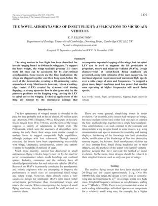
- 8. 3446 characteristic value for insects, and it offers a safe margin for increases with loading or manoeuvring. The aspect ratio AR ranges from approximately 5 to 12 for insects that do not use a clap-and-fling motion; 7 is a fairly typical value and will be used here. The mean lift coefficient CL in hovering and slow flight, with and without loads, is usually 2–3 or less (e.g. Ellington, 1984c; Ennos, 1989; Dudley and Ellington, 1990b; Cooper, 1993; Dudley, 1995; Willmott and Ellington, 1997b); a value of 2 will be used as a conservative upper limit. The steady-state profile drag coefficients for some insect wings have been measured at high angles of incidence in windtunnels. They scale with Reynolds number as (Ellington, 1984c): CD,pro = 7Re−1/2 , (9) where Re is given by equation 1. This relationship was derived from scant experimental data over the lower range of Re. It holds reasonably well for bumblebees and dragonflies at their higher Re (Dudley and Ellington, 1990b; Wakeling and Ellington, 1997a), but measurements on hawkmoth wings are significantly larger than the predicted values (Willmott and Ellington, 1997b). In all cases, the corresponding lift coefficients were much lower than those needed for weight support. Lacking studies that clarify this discrepancy and that compare steady-state values with unsteady results, we have had to persevere with equation 9 when estimating profile power. The recent discovery of the spiral LEV, however, has prompted J. R. Usherwood (personal communication) to suggest a much better alternative. Suction from the LEV causes a large normal force on the wing, with lift and drag components given by the cosine and sine of the effective angle of attack αr. C. P. ELLINGTON 1 2 5 10 20 50 100 200 1 2 5 10 20 50 100 Wing length (mm) Frequency(Hz) 10 ng 100 ng 100 g 10 g 1 g 100 mg 10 mg 1 mg 1 µg 10 µg 100 µµg 1 2 5 10 20 50 100 200 1 2 5 10 20 50 100 Wing length (mm) Frequency(Hz) 0.5 1 2 5 10 20 50 0.2 200 0.1 100 Fig. 5. Contours of the mass supported as functions of wingbeat frequency and wing length for a hovering insect-based flying machine. See text for values assigned to other parameters. Fig. 6. Contours of the mass-specific power (mWg−1) required for hovering as functions of wingbeat frequency and wing length. Fig. 7. Contours of maximum flight speed (ms−1) as functions of wingbeat frequency and wing length. Maximum speed is estimated from the flapping velocity during hovering and the advance ratio J=1. 1 2 5 10 20 50 100 200 1 2 5 10 20 50 100 Wing length (mm) Frequency(Hz) 0.01 0.1 1 10
- 9. 3447Insect flight and micro-air vehicles The LEV accounts for most of the wing force, so the lift-to- profile-drag ratio should simply be cotαr to a first approximation. Values of αr are typically approximately 30°, giving a ratio of 1.73; this is much lower than previous estimates but more realistic for such high-lift conditions. Equation 8 then reduces to: P*pro = 10.5ΦnR. (10) The lifting capacity, power requirement and predicted maximum speed are now just functions of wing length and frequency, as shown in Figs 5–7, respectively. The mass- specific aerodynamic power is the sum of the induced and profile powers and is equal to 32.8nR, given the selected values for Φ, CL and AR in equations 7 and 10. It is assumed that the kinetic energy of the flapping wings is stored elastically and that negligible power, other than aerodynamic, is required to sustain the oscillation. The first specification in a design study is probably the mass to be supported, and this is likely to prove a difficult target. Equation 6 shows that the mass is proportional to n2R4, so increases in R will be more effective in achieving the required mass than increases in n; e.g. doubling R will increase mass support 16-fold, whereas doubling n will increase it only fourfold. Therefore, within any limitations imposed by the design specifications, longer wings rather than higher frequencies offer a better route for mass support, as shown in Fig. 5. The aerodynamic power per unit mass is proportional to nR. To support the same target mass, R has to be increased much less than n, and hence the mass-specific power will be lower. The power saving can be very substantial, as shown in Figs 5 and 6: e.g. to support 200mg with R=10mm and n=200Hz requires an order of magnitude more power than with R=100mm and n=2Hz. Therefore, a given mass will be supported with less power by using a longer wing length and lower wingbeat frequency. The only disadvantage is that the maximum flight speed is 10 times lower for the larger design (Fig. 7). Flight speed is proportional to the flapping velocity and hence to nR. If mass support is achieved by small increases in R rather than larger ones in n, the speeds will necessarily be smaller. Mass, power and maximum speed are likely to be major design constraints for insect-based flapping machines. Small power plants with a high output per unit mass are a severe limitation at present, but internal combustion engines and lithium batteries can provide sufficient power for many of the examples given here. Longer wings are clearly advantageous for mass support and for power savings. Maximum speeds would be low but, because of their larger size, fabrication would be easier and they would offer a more convenient testbed for the development of control systems. This research is supported by the BBSRC and DARPA. References Betts, C. R. and Wootton, R. J. (1988). Wing shape and flight behaviour in butterflies (Lepidoptera: Papilionoidea and Hesperioidea): a preliminary analysis. J. Exp. Biol. 138, 271–288. Camhi, J. M. (1970). Yaw-correcting postural changes in locusts. J. Exp. Biol. 52, 519–531. Cooper, A. J. (1993). Limitations on bumblebee flight performance. PhD thesis, Cambridge University. Dickinson, M. H. and Götz, K. G. (1993). Unsteady aerodynamic performance of model wings at low Reynolds numbers. J. Exp. Biol. 174, 45–64. Dickinson, M. H. and Lighton, J. R. B. (1995). Muscle efficiency and elastic storage in the flight motor of Drosophila. Science 268, 87–90. Dudley, R. (1990). Biomechanics of flight in neotropical butterflies: morphometrics and kinematics. J. Exp. Biol. 150, 37–53. Dudley, R. (1995). Extraordinary flight performance of orchid bees (Apidae: Euglossini) hovering in heliox (80 % He/20% O2). J. Exp. Biol. 198, 1065–1070. Dudley, R. (2000). The Biomechanics of Insect Flight: Form, Function, Evolution. Princeton: University Press. Dudley, R. and DeVries, P. J. (1990). Flight physiology of migrating Urania fulgens (Uraniidae) moths: kinematics and aerodynamics of natural free flight. J. Comp. Physiol. A 167, 145–154. Dudley, R. and Ellington, C. P. (1990a). Mechanics of forward flight in bumblebees. I. Kinematics and morphology. J. Exp. Biol. 148, 19–52. Dudley, R. and Ellington, C. P. (1990b). Mechanics of forward flight in bumblebees. II. Quasi-steady lift and power requirements. J. Exp. Biol. 148, 53–88. Dugard, J. J. (1967). Directional changes in flying locusts. J. Insect Physiol. 13, 1055–1063. Ellington, C. P. (1984a). The aerodynamics of hovering insect flight. II. Morphological parameters. Phil. Trans. R. Soc. Lond. B 305, 17–40. Ellington, C. P. (1984b). The aerodynamics of hovering insect flight. III. Kinematics. Phil. Trans. R. Soc. Lond. B 305, 41–78. Ellington, C. P. (1984c). The aerodynamics of hovering insect flight. VI. Lift and power requirements. Phil. Trans. R. Soc. Lond. B 305, 145–181. Ellington, C. P. (1991a). Aerodynamics and the origin of insect flight. Adv. Insect Physiol. 23, 171–210. Ellington, C. P. (1991b). Limitations on animal flight performance. J. Exp. Biol. 160, 71–91. Ellington, C. P. (1995). Unsteady aerodynamics of insect flight. In Biological Fluid Dynamics (ed. C. P. Ellington and T. J. Pedley). Symp. Soc. Exp. Biol. 49, 109–129. Ellington, C. P., Machin, K. E. and Casey, T. M. (1990). Oxygen consumption of bumblebees in forward flight. Nature 347, 472–473. Ellington, C. P., van den Berg, C., Willmott, A. P. and Thomas, A. L. R. (1996). Leading-edge vortices in insect flight. Nature 384, 626–630. Ennos, A. R. (1989). The kinematics and aerodynamics of the free flight of some Diptera. J. Exp. Biol. 142, 49–85. Götz, K. G. (1987). Course-control, metabolism and wing interference during ultralong tethered flight in Drosophila melanogaster. J. Exp. Biol. 128, 35–46. Greenewalt, C. H. (1960). The wings of insects and birds as mechanical oscilllators. Proc. Am. Phil. Soc. 104, 605–611. Horridge, G. A. (1956). The flight of very small insects. Nature 178, 1334–1335. Josephson, R. K. (1981). Temperature and the mechanical
- 10. 3448 performance of insect muscle. In Insect Thermoregulation (ed. B. Heinrich), pp. 19–44. New York: John Wiley & Sons. Marden, J. H. (1987). Maximum lift production during takeoff in flying animals. J. Exp. Biol. 130, 235–258. Nachtigall, W. and Wilson, D. M. (1967). Neuromuscular control of dipteran flight. J. Exp. Biol. 47, 77–97. Osborne, M. F. M. (1951). Aerodynamics of flapping flight with application to insects. J. Exp. Biol. 28, 221–245. van den Berg, C. and Ellington, C. P. (1997a). The vortex wake of a ‘hovering’ model hawkmoth. Phil. Trans. R. Soc. Lond. B 352, 317–328. van den Berg, C. and Ellington, C. P. (1997b). The three- dimensional leading-edge vortex of a ‘hovering’ model hawkmoth. Phil. Trans. R. Soc. Lond. B 352, 329–340. Vogel, S. (1967). Flight in Drosophila. II. Variations in stroke parameters and wing contour. J. Exp. Biol. 46, 383–392. Wakeling, J. M. and Ellington, C. P. (1997a). Dragonfly flight. I. Gliding flight and steady-state aerodynamic forces. J. Exp. Biol. 200, 543–556. Wakeling, J. M. and Ellington, C. P. (1997b). Dragonfly flight. II. Velocities, accelerations and kinematics of flapping flight. J. Exp. Biol. 200, 557–582. Wakeling, J. M. and Ellington, C. P. (1997c). Dragonfly flight. III. Lift and power requirements. J. Exp. Biol. 200, 583–600. Weis-Fogh, T. (1972). Energetics of hovering flight in hummingbirds and in Drosophila. J. Exp. Biol. 56, 79–104. Weis-Fogh, T. (1973). Quick estimates of flight fitness in hovering animals, including novel mechanisms for lift production. J. Exp. Biol. 59, 169–230. Weis-Fogh, T. (1975a). Unusual mechanisms for the generation of lift in flying animals. Scient. Am. 233, 80–87. Weis-Fogh, T. (1975b). Flapping flight and power in birds and insects, conventional and novel mechanisms. In Swimming and Flying in Nature, vol. 2 (ed. T. Y. Wu, C. J. Brokaw and C. Brennen), pp. 729–762. New York: Plenum Press. Willmott, A. P. and Ellington, C. P. (1997a). The mechanics of flight in the hawkmoth Manduca sexta. I. Kinematics of hovering and forward flight. J. Exp. Biol. 200, 2705–2722. Willmott, A. P. and Ellington, C. P. (1997b). The mechanics of flight in the hawkmoth Manduca sexta. II. Aerodynamic consequences of kinematic and morphological variation. J. Exp. Biol. 200, 2723–2745. Willmott, A. P., Ellington, C. P. and Thomas, A. L. R. (1997). Flow visualization and unsteady aerodynamics in the flight of the hawkmoth Manduca sexta. Phil. Trans. R. Soc. Lond. B 352, 303–316. Wootton, R. J. (1981). Palaeozoic insects. Annu. Rev. Ent. 26, 319–344. Wootton, R. J. (1990). The mechanical design of insect wings. Scient. Am. 262, 114–120. Wootton, R. J. (1995). Geometry and mechanics of insect hindwing fans – a modeling approach. Proc. R. Soc. Lond. B 262, 181–187. Zanker, J. M. (1990). The wingbeat of Drosophila melanogaster. I. Kinematics. Phil. Trans. R. Soc. Lond. B 327, 1–18. C. P. ELLINGTON