This document discusses methods for estimating the propulsive power required to propel a ship at a given speed. It explains that the power estimate is needed to determine machinery masses and fuel consumption. The power can be estimated from tests of similar existing vessels or models. Scaling laws must be applied when estimating power for a different sized craft. The effective power required to drive the ship is less than the power delivered to the propulsion unit due to efficiency losses. Common propulsion systems include diesel, gas turbine, steam turbine and electric, each with their own advantages and limitations. The overall assessment requires knowledge of the required thrust at a given speed, available propulsion engines, and propulsor options.
Human: Thank you, that is


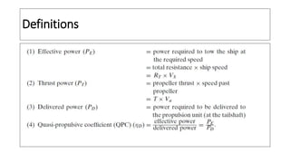
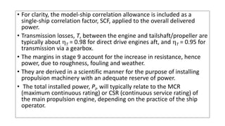
![• A fundamental requirement of any ship propulsion system is the
efficient conversion of the power (P) available from the main
propulsion engine(s) [prime mover] into useful thrust (T) to propel
the ship at the required speed (V),
• There are several forms of main propulsion engines including:
• Diesel.
• Gas turbine.
• Steam turbine.
• Electric.
• (And variants / combinations of these).](https://image.slidesharecdn.com/2-propulsivepower-220724115617-0328fa8c/85/2-Propulsive-Power-pptx-6-320.jpg)


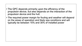

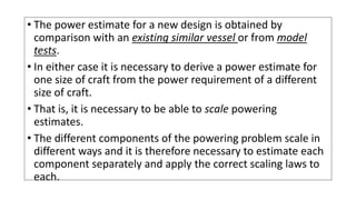
![propeller detail main engine
D(m) = 4.000 Pm(kW) = 1750 1750
Ratio= 7.200 Nm(RPM)= 900
Np(RPM)= 125 DUCTED PROPELLER
Vs Pe Pd Pbmin N Nmak
(knots) (kWs) (kWs) (kWs) (RPM) (RPM)
10.0 585 0.279 0.248 1.044 0.624 1.015 0.661 885 917 107 768
10.5 688 0.279 0.248 1.044 0.624 1.015 0.661 1041 1079 113 811
11.0 809 0.279 0.248 1.044 0.623 1.015 0.660 1226 1270 119 855
11.5 950 0.279 0.248 1.044 0.622 1.015 0.659 1442 1494 125 900
12.0 1114 0.279 0.248 1.044 0.620 1.015 0.657 1696 1758 132 948
12.5 1307 0.279 0.248 1.043 0.618 1.015 0.655 1997 2069 139 998
Not: %100 MCR ve deniz marjini olmaksızın asgari makina gücü Pbmin; h tr = 0.965 olarak hesaplanmıştır.
wt t H 0 r d
0
500
1000
1500
2000
2500
3000
3500
4000
7.0 8.0 9.0 10.011.012.013.014.015.0
Power
[kW]
Speed [knots]
Pe
Pbmin](https://image.slidesharecdn.com/2-propulsivepower-220724115617-0328fa8c/85/2-Propulsive-Power-pptx-18-320.jpg)


