2. ST
ARTING SYSTEM
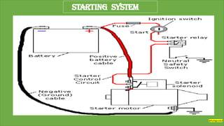
The starting system includes the battery, starter
motor,
solenoid, ignition switch, and in some cases, a starter relay.
A neutral safety switch is included in the starting system circuit to
prevent the vehicle from being accidentlystarted while in gear.
@Autogurukul
3. BATTERY
An electrochemical device for storing energy in chemical
form so that it can be released as electricity for cranking the engine and
powering the electrical load. Also a group of electric cells connected
together.
@Autogurukul
4. Starter motor
A starter is an electric motor that turns over or"cranks" the engine to startit.
A starter consists of the very powerful DC electric motor and the starter
solenoid that is usually attached to the motor
Inside, a typical starter motor has the electric windings (coils) attached to the starter motor
housing and the armature (the rotating part) that is connected through the carbon brushes in
series with the windings.
On the front end of the armature, there is a small gear that attached to the armature through an
overrunning clutch. This part is commonly known as theBendix.
@Autogurukul
5. STARTER MOTOR
A small, powerful electric motor that converts electrical
energy from the battery into mechanical energy to spin the crankshaft
and start theengine
@Autogurukul
6. SOLENOID
An electromechanical device which, when connected to an electrical source such as a
battery, produces a mechanicalmovement. The starter solenoid works as a powerful
electric relay -when activated, it closes the electric circuit and sends the battery
power to the starter motor.
At the same, the starter solenoid pushes the starter gear forward to mesh with
the engine flywheel.
A typical starter solenoid has one small connector for the control wire and two large
terminals: one for the positive battery cable and the other for the starter motor.
@Autogurukul
7. IGNITION SWITCH
The key-operated main power switch that opens and closes the circuit that supplies
current to theignition and other electrical systems
.
@Autogurukul
8. NEUTRAL SAFETY SWITCH
A switch wired into the ignition switch to prevent engine cranking unless the
transmission shift lever is in NEUTRAL.
@Autogurukul
9. STARTER RELAY
STARTER RELAY-An electrical device that opens or closes a circuit in response to a
voltage signal.
@Autogurukul
10. Battery cables
A starter motor requires a very high
current to crank the engine, that's why
it's connected tothe battery with thick
(large gauge) cables.
The negative (ground) cable connects
the"-"battery terminal to the engine
cylinder block close to the starter.
The positive cable connects the "+"
battery terminal tothe starter .solenoid.
@Autogurukul
11. To start the automobile engine, the crankshaft must turn fast enough for air-
fuel mixture to enter the cylinders.
An electric starter or starting motor does this job.
It converts electrical energy from the battery into mechanical energy that
rotates the crankshaft.
The starting system has 2 separated but related circuits
1.Low-current control circuit
2. High-current motor circuit
both operate on battery voltage.
(thin arrows)
(thick arrows)
@Autogurukul
12. When the driver turns the ignition key to START, the CONTROL CIRCUIT causes
heavy contacts to close in a starter relay or solenoid switch.
High current then flows from the battery insulated Cable through these contacts
to the starting motor.
A gear on the starting motor shaft moves into mesh with the ring gear
around the engine flywheel or drive plate.
As the starting-motor shaft turns, it spins the crankshaft fast enough to
start the engine.
@Autogurukul
13. • Describe how the cranking circuit works.
• Explain how to disassemble and reassemble a
starter motor and solenoid.
• Discuss how to test the cranking circuit.
• Describe how to perform cranking system testing
procedures.
OBJECTIVES:
@Autogurukul
14. ampere-turns • armature
bench testing • brush-end housing • brushes
commutator-end housing • commutator segments • compound
motor (compound-wound) • compression spring • counter-
electromotive force (CEMF) • cranking circuit
drive coil • drive-end (DE) housing • electromagnetic switch
field coils • field poles
KEY TERMS:
Continued
@Autogurukul
15. gear-reduction starters • ground brushes • growler tester
holding coil • hold-in winding • hot brushes
lap winding
main field housing • mesh spring • mica • movable pole shoe
neutral safety switch • overrunning clutch
permanent-magnet field • plunger lever • pole shoes • positive-
engagement starter • pull-in winding
KEY TERMS:
@Autogurukul
16. remote vehicle start (RVS)
series motor • shift fork lever • shunt motor • solenoid-operated
starter • starter drive
through bolts
undercut
voltage-drop testing
wave winding
KEY TERMS:
@Autogurukul
17. For any engine to start, it must first be rotated.
It is the purpose and function of the cranking circuit to create
the necessary power by converting electrical energy from the
battery into mechanical energy at the starter motor and rotate
the engine.
@Autogurukul
18. CRANKING CIRCUIT
The cranking circuit includes mechanical and electrical parts
required to crank the engine for starting. Early 1900s cranking
force was the driver’s arm. Modern cranking circuits include:
Continued
1. The Starter motor. The starter is normally a 0.5- to 2.6-
horsepower (0.4 to 2.0 kilowatts) electric motor that develops
nearly 8 horsepower
(6 kilowatts) for a very
short time when first
cranking a cold engine.
Figure 40–1
A typical solenoid-operated starter.
@Autogurukul
19. 2. The Battery. The battery must be of the correct capacity and
be at least 75% charged to provide the necessary current and
voltage for correct operation of the starter.
3. The Starter solenoid or relay. The high current required by
the starter must be able to be turned on and off. A large
switch would be required if the current were controlled by
the driver directly. Instead, a small current switch (ignition
switch) operates a solenoid or relay that controls the high
starter current.
4. The Starter drive. The starter drive uses a small gear that
contacts the engine flywheel gear and transmits starter motor
power to rotate the engine.
Continued
@Autogurukul
20. Figure 40–2 Some column-
mounted ignition switches act
directly on the contact points,
whereas others use a link from
lock cylinder to ignition switch.
Figure 40–3 A typical wiring diagram of a starter circuit.
5. The Ignition switch The ignition switch and safety control
switches control the starter motor operation.
Continued
The engine is cranked by an
electric motor controlled by a
key-operated ignition switch.
@Autogurukul
21. The ignition switch will not operate the starter unless the
transmission is in neutral or park. Many manufacturers a neutral
safety switch that opens the circuit between ignition switch and
starter to prevent operation unless the gear selector is in neutral or
park.
Neutral safety switches can be adjusted by loosening the hold-down
screws and moving the switch slightly to be certain the engine will
crank only with the transmission in the neutral and park positions.
Many manufacturers use a mechanical blocking device in the
steering column to prevent the driver from turning the key switch to
start unless the gear selector is in neutral or park. Many manual
transmission vehicles also use a safety switch to permit cranking
only if the clutch is depressed.
Continued
@Autogurukul
22. Whenever diagnosing any starter-related problem, open the door of the
vehicle and observe the brightness of the dome or interior light(s) while
attempting to crank the engine. Why?
Watch the Dome Light
• The brightness of any electrical lamp is proportional to the voltage.
• Normal operation of the starter results in a slight dimming of the dome
light.
• If the light remains bright, the problem is usually an open circuit in the
control circuit.
• If the light goes out or almost goes out, the problem is usually a
discharged or defective battery or a shorted or grounded armature of
field coils inside the starter.
@Autogurukul
23. COMPUTER-CONTROLLED STARTING
Some key-operated and most push-button-to-start ignition systems
use the computer to crank the engine. The ignition switch start
position on the push-to-start button is used as an input signal to
the power train control module (PCM).
The ignition key can be turned to the start position, released, and
the PCM cranks the engine until it senses that the engine has
started. The PCM can detect that the engine has started by looking
at the engine speed signal.
Normal cranking speed can vary between 100 and 250 rpm. If it
exceeds 400 rpm, the PCM determines the engine started and
opens the circuit to the “S” (start) terminal of the starter solenoid.
Continued
@Autogurukul
24. Some customers have complained that the engine cranks after they
release the ignition key and assume that there is a fault with the ignition
switch or starter circuit. If the vehicle is equipped with computer-controlled
starting, it is normal for the engine to crank until it starts and it may crank
longer than the customer thinks it should especially in cold weather.
Check That Extended Cranking May Be
Normal Operation
Computer-controlled starting is almost always part of the system if a push-
button start is used.
Before the PCM cranks the engine, the following conditions must be met:
The brake pedal is depressed.
The gear selector is in Park or Neutral.
The correct key fob (code) is present in the vehicle.
Continued
@Autogurukul
25. Figure 40–4 The top button on this key fob is the
remote start button.
Remote vehicle start (RVS) is a system that allows the driver to
start the engine of the vehicle from inside the house or building
from a distance of about 200 feet (65 meters).
The doors remain locked so the
possibility of theft is reduced.
This feature allows the heater or
air-conditioning system to start
before the driver arrives.
NOTE: Most remote start systems will turn off the engine after 10
minutes of run time unless reset by the use of the remote.
@Autogurukul
26. HOW THE STARTER MOTOR WORKS
A starter consists of a main field housing, one end of which is
called a commutator-end (or brush-end) housing and the other
end a drive-end housing.
The drive-end housing contains the drive pinion gear, which
meshes with the engine flywheel gear teeth to start the engine.
The commutator-end plate supports the end containing the starter
brushes. Through bolts hold the three components together.
See Figure 40–5.
Continued
@Autogurukul
27. Figure 40–5 A typical starter motor.
Continued
@Autogurukul
28. A starter uses electromagnetic principles to convert electrical energy
(up to 500 amps) to mechanical power [up to 8 hp (6 kw)] to crank
the engine.
The steel housing of the starter motor contains four electromagnets
that are connected directly to the positive post of the battery to
provide a strong magnetic field inside the starter. Current for the
starter is controlled by a solenoid or relay controlled by the driver-
operated ignition switch.
The electromagnets use heavy copper or aluminum wire wrapped
around a soft-iron core. The core is contoured to fit against the
rounded internal surface of the starter frame. The soft-iron cores are
called pole shoes.
Continued
@Autogurukul
29. Two of the four pole shoes are wrapped with copper wire in one
direction to create a north pole magnet, the others wrapped to create
a south pole.
When energized, these magnets create strong magnetic fields inside
the starter housing. They are called field coils. The soft-iron cores
(pole shoes) are called field poles.
Inside the field coils is an armature supported with bushings at
both ends, which permit it to rotate. It is constructed of thin, circular
disks of steel laminated together and wound lengthwise with heavy-
gauge insulated copper wire.
The laminated iron core supports the copper loops of wire and helps
concentrate the magnetic field produced by the coils.
Continued
@Autogurukul
30. The ends of the copper armature windings are soldered to the
commutator segments. Current passing through the field coils is
connected to the commutator of the armature by brushes that can
move over the segments of the rotating armature. They are made of
copper and carbon. Copper is a good conductor, and carbon added
to starter brushes helps provide graphite-type lubrication needed to
reduce wear of brushes and commutator segments.
The starter uses four brushes—two to transfer current from field
coils to armature, and two for the ground return path for current
flow through the armature. See Figure 40–6.
Two hot brushes are in holders, insulated from the housing. Two
ground brushes primarily use bare, stranded copper wire
connections to the brushes. The ground brush holders are not
insulated and attach directly to the field housing.
Continued
@Autogurukul
31. Figure 40–6 This series-wound electric motor shows the basic operation with only two
brushes: one hot brush and one ground brush. The current flows through both field coils, then
through the hot brush and through the loop winding of the armature before reaching ground
through the ground brush.
Current travels through
brushes into armature
windings, where other
magnetic fields are
created around each
copper wire loop in
the armature.
The two magnetic
fields created inside
the starter housing
create force that
rotates the armature.
@Autogurukul
32. HOW MAGNETIC FIELDS TURN AN ARMATURE
A magnetic field surrounds every conductor carrying a current.
Field strength is increased as current flow (in amps) is increased.
Inside the starter housing is a strong magnetic field created by the
field coil magnets. The armature, a conductor, is inside this strong
field, with little clearance between armature and field coils.
The two magnetic fields act together, and their lines of force
“bunch up” or are strong on one side of the armature loop wire
and become weak on the other side of the conductor.
This causes the conductor (armature) to move from the area of
strong magnetic field strength toward the area of weak magnetic
field strength. This causes the armature to rotate.
Continued
@Autogurukul
33. Figure 40–7 The interaction of the magnetic fields of the armature loops and field coils
creates a stronger magnetic field on the right side of the conductor, causing the armature
loop to move toward the left.
Continued
@Autogurukul
34. Figure 40–8 The armature loops rotate due to the difference in the strength of the magnetic
field. The loops move from a strong magnetic field strength toward a weaker magnetic field
strength.
This rotation force (torque) is increased as the current flowing
through the starter motor increases. The torque of a starter is
determined by the strength of the magnetic fields inside the starter.
Magnetic field strength is measured in ampere-turns.
Continued
@Autogurukul
35. Figure 40–9 Pole shoes and field
windings installed in the housing.
If the current or number of turns of wire are increased, magnetic
field strength is increased.
The pole shoes are
made of iron and are
attached to the frame
with large screws.
The magnetic field
of the starter motor
is provided by two
or more pole shoes
and field windings.
Continued
@Autogurukul
36. This shows paths of
magnetic flux lines
within a four-pole
motor.
The field windings
are usually made of
heavy copper ribbon
to increase current-
carrying capacity
and electromagnetic
field strength.
Figure 40–10
Magnetic lines of
force in a four-pole
motor.
Continued
@Autogurukul
37. Starter motors usually have four pole shoes and two to four field
windings to provide a strong magnetic field within the motor.
Pole shoes that do not have field windings are magnetized by flux
lines from the wound poles.
Figure 40–11 A
pole shoe and
field winding.
@Autogurukul
38. TYPES OF STARTER MOTORS
Starter motors provide high power at low starter motor speeds to
crank an automotive engine at all temperatures and at cranking
speed required for the engine to start (60 to 250 engine rpm).
Continued
Figure 40–12 This wiring diagram illustrates the construction of a series-wound electric
motor. All current flows through the field coils, then the armature (in series) before
reaching ground.
Electric motors are classified according to the internal electrical
motor connections. Many starter motors are series wound, which
means the current flows first through the field coils, then in series
through the armature, and finally through the ground brushes.
@Autogurukul
39. Series Motors A series motor develops maximum torque at initial
start (0 rpm) and less torque as speed increases. Commonly used for
an automotive starter motor because of high starting power
characteristics.
Less torque develops at high RPM because a current produced in
the starter itself acts against current from the battery. Called counter
electromotive force or CEMF, this current works against battery
voltage and is produced by electromagnetic induction in the
armature conductors. This induced voltage operates against applied
voltage supplied by the battery, reduces strength of the magnetic
field in the starter and current draw of the starter.
It is characteristic of series-wound motors to keep increasing in
speed under light loads, which could lead to destruction of the
starter motor unless controlled or prevented.
Continued
@Autogurukul
40. Shunt Motors Shunt-type electric motors have field coils in
parallel (or shunt) across the armature as shown here. A shunt
motor does not decrease in torque at higher motor rpm, because the
CEMF produced not decrease the field coil strength.
Continued
Figure 40–13 This wiring diagram illustrates construction of a shunt-type electric motor. Shunt
type electric motors have the field coils in parallel (or shunt) across the armature as shown.
Small electric motors used in blower motors, windshield wipers,
power windows, and power seats use permanent magnets.
A shunt motor, however, does not produce as high a starting torque
as that of a series-wound motor, and is not used for starters.
To compensate for the lack of
torque, all PM starters use
gear reduction to multiply
starter motor torque.
@Autogurukul
41. Compound Motors A compound-wound, or compound, motor
has operating characteristics of a series motor and a shunt-type
motor, because some of the field coils are connected to the armature
in series and some (usually only one) are connected directly to the
battery in parallel (shunt) with the armature.
Figure 40–14
A compound motor is a
combination of series and shunt
types, using part of the field
coils connected electrically in
series with the armature and
some in parallel (shunt).
Compound-wound starter motors are commonly used in Ford, GM
and Chrysler starters. The shunt-wound field coil is called a shunt
coil and is used to limit maximum speed of the starter.
@Autogurukul
42. ARMATURE AND COMMUTATOR ASSEMBLY
The motor armature shown has a laminated core. Insulation
between laminations helps reduce eddy currents. For reduced
resistance, armature conductors are made of a thick copper wire.
Continued
Figure 40–15 A typical starter motor armature.
@Autogurukul
43. Armatures are connected to the commutator in one of two ways. In a
lap winding, the two ends of each conductor are attached to two
adjacent commutator bars.
Figure 40–16 An armature
lap winding.
In a wave winding, the two ends
are attached to commutator bars
180 degrees apart (on opposite
sides of the commutator).
A lap-wound armature is more
commonly used because it offers
less resistance.
The commutator is made of
copper bars insulated from each
other by mica or some other
insulating material.
Continued
@Autogurukul
44. Figure 40–17 The pinion gear meshes with the fly wheel ring gear.
Armature core, windings, and
commutator are assembled on
a long armature shaft.
This shaft also carries the
pinion gear that meshes with
the engine flywheel ring gear.
The shaft is supported by
bearings or bushings in the
end housings.
To supply the proper current
to the armature, a four-pole
motor must have four brushes
which are held against the
commutator by spring force.
Continued
@Autogurukul
45. Figure 40–18 A cutaway of a typical starter motor.
@Autogurukul
46. PERMANENT MAGNET FIELDS
Permanent-magnet starter motors were developed by General
Motors for automotive use in the mid-1980s. The permanent
magnets used are an alloy of neodymium, iron, and boron.
Almost 10 times more powerful than permanent magnets used
previously, permanent-magnet, planetary-drive starter motors are
the first significant advance in starter design in decades. First
introduced on Chrysler and GM models.
Permanent magnets are used in place of the electromagnetic field
coils and pole shoes, eliminating the motor field circuit, which
eliminates wire-to-frame shorts, field coil welding, and other
problems. The motor has only an armature circuit.
@Autogurukul
47. Figure 40–19 This starter permanent-magnet field
housing was ruined when someone used a hammer on
the field housing in an attempt to “fix” a starter that
would not work. A total replacement is the only
solution in this case.
Most of today’s starters use permanent-magnet fields, and the
magnets can be easily broken if hit. A magnet that is broken
becomes two weaker magnets.
Some early PM starters used
magnets that were glued or
bonded to the field housing.
If struck with a heavy tool,
magnets could be broken,
with parts of the magnet
falling onto the armature
and into the bearing pockets,
making the starter impossible
to repair or rebuild.
@Autogurukul
48. In the past, it was common to see service technicians hitting a starter in
their effort to diagnose a no-crank condition. Often the shock of the blow to
the starter aligned or moved the brushes, armature, and bushings. Many
times, the starter functioned after being hit—even if only for a short time.
However, most of today’s starters use permanent-magnet fields, and the
magnets can be easily broken if hit. A magnet that is broken becomes two
weaker magnets. Some early PM starters used magnets that were glued or
bonded to the field housing. If struck with a heavy tool, the magnets could
be broken, with parts of the magnet falling onto the armature and into the
bearing pockets, making the starter impossible to repair or rebuild.
Don’t Hit That Starter!
@Autogurukul
49. GEAR REDUCTION STARTERS
Gear-reduction starters are used by many manufacturers. The
purpose of reduction (typically 2:1 to 4:1) is to increase speed of
the armature of the starter and provide the torque multiplication
necessary to crank an engine. See Figure 40–20.
A starter motor’s maximum torque occurs at zero rpm and torque
decreases with increasing rpm. A smaller starter using a gear-
reduction design can produce the necessary cranking power with
reduced starter amperage requirements.
Lower current requirements mean smaller battery cables can be
used. Permanent-magnet starters use a planetary gear set (a type of
gear reduction) to provide the necessary torque for starting.
Continued
@Autogurukul
50. Figure 40–20 Many gear-reduction starters use a planetary gear-reduction assembly similar to
that used in an automatic transmission.
@Autogurukul
51. STARTER DRIVES
A starter drive includes a small pinion gear that meshes with and
rotates the larger gear on the flywheel for starting.
Continued
The ends of the starter
pinion gear are tapered to
help the teeth mesh more
easily without damaging
the flywheel ring gear
teeth.
Figure 40–21
A cutaway of a typical starter drive.
@Autogurukul
52. The pinion gear must engage with the engine gear slightly before
the starter motor rotates, to prevent serious damage to either the
starter gear or the engine, but the pinion gear must be disengaged
after the engine starts.
The ratio of teeth on the engine gear to the number on the starter
pinion is between 15:1 and 20:1. A typical small starter pinion gear
has 9 teeth that turn an engine gear with 166 teeth. This provides an
18:1 gear reduction; thus, the starter motor is rotating approximately
18 times faster than the engine.
Continued
@Autogurukul
53. Figure 40–22 The ring gear to
pinion gear ratio is usually 15:1 to
20:1
Normal cranking speed for
the engine is 200 rpm. This
means that the starter motor
speed is 18 times faster, or
3600 starter rpm (200 × 18
= 3600).
If the engine started and
accelerated to 2000 rpm
(normal cold engine speed),
the starter would be
destroyed by the high
speed (36,000 rpm) if
not disengaged from the
engine.
@Autogurukul
54. Older-model starters often used a Bendix drive mechanism, which
used inertia to engage the starter pinion with the engine flywheel
gear. Inertia is the tendency of a stationary object to remain
stationary, because of its weight, unless forced to move.
On these older-model starters, the small starter pinion gear was
attached to a shaft with threads, and the weight of this gear caused it
to be spun along the threaded shaft and mesh with the flywheel
whenever the starter motor spun.
If the engine speed was greater than the starter speed, the pinion
gear was forced back along the threaded shaft and out of mesh with
the flywheel gear.
Continued
@Autogurukul
55. All starter drive mechanisms use a type of one-way clutch that
allows the starter to rotate the engine, but turns freely if engine
speed is greater than starter motor speed.
This clutch is called an overrunning clutch and protects the starter
motor from damage if the ignition switch is held in the start position
after engine start.
The overrunning clutch, which is built in as a part of the starter
drive unit, uses steel balls or rollers installed in tapered notches.
Whenever the engine rotates faster than the starter pinion, the balls
or rollers are forced out of the narrow tapered notch, allowing the
pinion gear to turn freely (overruns).
See Figure 40–23.
Continued
@Autogurukul
56. Figure 40–23 Operation of the overrunning clutch. (a) Starter motor is driving the starter pinion
and cranking the engine. The rollers are wedged against spring force into their slots. (b) The
engine has started and is rotating faster than the starter armature. Spring force pushes the
rollers so they can rotate freely.
(a) (b)
This taper forces the balls or rollers tightly into the notch, when
rotating in the direction necessary, to start the engine.
Continued
@Autogurukul
57. The spring between the drive tang or pulley and overrunning clutch
and pinion is called a mesh spring and it helps cushion and control
engagement of the starter drive pinion with the flywheel gear.
Figure 40–24
Cutaway of a solenoid-activated starter showing the solenoid, shift lever, and starter drive
assembly that includes the starter pinion and overrunning clutch with a mesh spring in one unit.
This spring is called a
compression spring
because the starter
solenoid or starter yoke
compresses the spring
and the spring tension
causes the starter pinion
to engage the engine
flywheel.
Continued
@Autogurukul
58. STARTER DRIVE OPERATION
The starter drive (pinion gear) must be moved into mesh with the
engine ring gear before the starter motor starts to spin. Most
starters use a solenoid or magnetic pull of the shunt coil in the
starter to engage the starter pinion.
A starter drive is generally dependable and does not require
replacement unless defective or worn. Major wear occurs in the
overrunning clutch section of the starter drive unit.
The steel balls or rollers wear and often do not wedge tightly into
the tapered notches as is necessary for engine cranking.
Continued
@Autogurukul
59. A worn starter drive can cause the starter motor to operate freely,
not rotate the engine, and makes “whining” noise. The whine
indicates the starter motor is operating and the starter drive is not
rotating the engine flywheel.
The entire starter drive is replaced as a unit. The overrunning clutch
section of the starter drive cannot be serviced or repaired separately
because the drive is a sealed unit.
Starter drives are most likely to fail intermittently at first, then more
frequently, until replacement becomes necessary. Intermittent starter
drive failure (starter whine) is often most noticeable during cold
weather.
@Autogurukul
60. Figure 40–25
A Ford movable-pole-shoe starter.
Positive-engagement starters,
used on some old Ford engines,
utilize the shunt coil winding
of the starter to engage the
starter drive.
High starting current is
controlled by an ignition
switch–operated starter
solenoid, usually mounted
near the positive battery post.
Continued
POSITIVE ENGAGEMENT STARTERS
@Autogurukul
61. When this control circuit is closed, current flows through a hollow
coil (called a drive coil) that attracts a movable pole shoe. The
movable metal pole shoe is attached to and engages the starter
drive with a lever (called the plunger lever).
When the starter drive has engaged the engine flywheel, a tang on
the movable pole shoe “opens” a set of contact points. The contact
points provide the ground return path for the drive coil operation.
The movable pole shoe is held down (which keeps the starter
drive engaged) by a smaller coil on the inside of the main drive
coil.
This coil is called the holding coil and it is strong enough to hold
the starter drive engaged while permitting the flow of the
maximum possible current to operate the starter.
Continued
@Autogurukul
62. If the grounding contact points are severely pitted, the starter may
not operate the starter drive or the starter motor because of the
resulting poor ground for the drive coil.
If the contact points are bent or damaged enough to prevent them
from opening, the starter will “clunk” the starter drive into
engagement but will not allow the starter motor to operate.
@Autogurukul
63. SOLENOID OPERATED STARTERS
A starter solenoid is an electromagnetic switch containing two
separate but connected electromagnetic windings. This switch is
used to engage the starter drive and to control the current from the
battery to the starter motor.
Continued
The two internal windings contain approximately the same number
of turns but are made from a different gauge wire. Together both
windings produce a strong magnetic field that pulls a metal plunger
into the solenoid.
The plunger is attached to the starter drive through a shift fork lever.
When the ignition switch is turned to the start position, the motion
of the plunger into the solenoid causes the starter drive to move into
mesh with the flywheel ring gear.
@Autogurukul
64. Figure 40–26 Wiring diagram of a typical starter solenoid. Notice that both the pull-in
winding and the hold-in winding are energized when the ignition switch is first turned to the
“start” position. As soon as the solenoid contact disk makes electrical contact with both B and
M terminals, the battery current is conducted to the starter motor and electrically neutralizes
the pull-in winding.
The heavier-gauge
winding (called the
pull-in winding) is
needed to draw the
plunger into the
solenoid.
The lighter-gauge
winding (called the
hold-in winding)
produces enough
magnetic force to
keep the plunger
in position.
@Autogurukul
65. The main purpose of using two separate windings is to permit as
much current as possible to operate the starter and yet provide the
magnetic field required to move the starter drive into engagement.
The instant the plunger is drawn into the solenoid enough to engage
the starter drive, the it makes contact with a metal disk that connects
the battery terminal post of the solenoid to the motor terminal.
This permits full battery current to flow through the solenoid to
operate the starter motor. The contact disk also electrically bypasses
the pull-in winding.
The solenoid has to work to supply current to the starter. If the
starter motor operates at all, the solenoid is working, even though it
may have high external resistance that could cause slow starter
motor operation.
@Autogurukul
66. STARTING SYSTEM TROUBLESHOOTING
Proper operation of the starting system depends on a good battery,
cables and connections, and good starter motor. Because a starting
problem can be caused by a defective component anywhere in the
starting circuit, it is important to check for the proper operation of
each part of the circuit to diagnose and repair the problem quickly.
Continued
@Autogurukul
67. VOLTAGE DROP TESTING
Voltage drop is the drop in voltage that occurs when current is
flowing through a resistance.
A voltage drop is the difference between voltage at the source and
voltage at the electrical device to which it is flowing. The higher
the voltage drop, the greater the resistance in the circuit.
Continued
NOTE: Before a difference in voltage (voltage drop) can be measured
between the ends of a battery cable, current must be flowing through the
cable. Resistance is not effective unless current is flowing. If the engine is
not being cranked, current is not flowing through the battery cables and
the voltage drop cannot be measured.
@Autogurukul
68. Many techs have asked, “Why measure voltage drop when resistance can
be easily measured using an ohmmeter?” Think of a battery cable with all
strands of the cable broken, except for one strand.
Voltage Drop is Resistance - Part 1
If an ohmmeter were used to measure the resistance of the cable, the reading
would be very low, probably less than 1 ohm. However, the cable is not
capable of conducting the amount of current necessary to crank the engine.
In less severe cases, several strands can be broken and can affect the
operation of the starter motor. While the resistance of the battery cable
will not indicate any increased resistance, the restriction to current flow
will cause heat and a decrease in the voltage available at the starter.
Since resistance is not effective until current flows, measuring the
voltage drop (differences in voltage between two points) is the most
accurate method of determining the true resistance in a circuit. How
much is too much?
@Autogurukul
69. According to Bosch Corporation, all electrical circuits should have a
maximum of 3% loss of the voltage of the circuit to resistance. Therefore,
in a 12-volt circuit, the maximum loss of voltage in cables and connections
should be 0.36 volt (12 X 0.03 = 0.36 volt.) The remaining 97% of the
circuit voltage (11.64 volts) is available to operate the electrical device
(load). Just remember:
Voltage Drop is Resistance - Part 2
• Low-voltage drop Low resistance
• High-voltage drop High resistance
@Autogurukul
70. Even though voltage-drop testing can be performed on any
electrical circuit, the most common areas of testing include the
cranking circuit and the charging circuit wiring and connections.
Continued
High-voltage drop (high resistance) in the cranking circuit wiring
can cause slow engine cranking with less than normal starter
amperage drain as a result of excessive circuit resistance.
If voltage drop is high enough, such as could be caused by dirty
battery terminals, the starter may not operate. A typical symptom of
high resistance in the cranking circuit is a “clicking” of the starter
solenoid.
Voltage-drop testing of the wire involves connecting any voltmeter
(on the low scale) to the suspected high-resistance cable ends and
cranking the engine. See Figures 40–27 through 40–29.
@Autogurukul
71. Figure 40–27 Voltmeter hookups for voltage-drop testing of a
cranking circuit.
Continued
@Autogurukul
72. Figure 40–28 Voltmeter hookups for voltage-drop testing of a
Ford-type cranking circuit.
Continued
@Autogurukul
73. Figure 40–29 To test the voltage drop
of the battery cable connection, place
one voltmeter lead on the battery
terminal and the other voltmeter lead
on the cable end and crank the engine.
The voltmeter will read the difference
in voltage between the two leads which
should not exceed 0.2 volt (200 mV).
NOTE: Before a difference in voltage (voltage drop) can be measured
between the ends of a battery cable, current must be flowing through the
cable. Resistance is not effective unless current is flowing. If the engine is
not being cranked, current is not flowing through the battery cables and
the voltage drop cannot be measured.
@Autogurukul
74. Crank the engine with a voltmeter connected to the battery and
record the reading, then again with the voltmeter connected across
the starter and record the reading. If the difference in the two
readings exceeds 0.5 volt, perform the following to determine the
exact location of the voltage drop.
Step #1 Connect the positive voltmeter test lead to the most-
positive end of the cable being tested. The most-positive end of a
cable is the end closest to the positive terminal of the battery.
Step #2 Connect the negative voltmeter test lead to the other end of
the cable being tested. With no current flowing through the cable,
the voltmeter should read zero because both ends of the cable have
the same voltage.
Continued
Voltage Drop Test
@Autogurukul
75. Step #3 Crank the engine; voltmeter should read less than 0.2 volt.
Step #4 Evaluate results. If the voltmeter reads zero, the cable
being tested has no resistance and is good. If the voltmeter reads
higher than 0.2 volt, the cable has excessive resistance and should
be replaced. Before replacing the cable, make certain connections at
both ends of the cable being tested are clean and tight.
Continued
If a cable or connection is hot to the touch, there is electrical resistance in
the cable or connection. The resistance changes electrical energy into heat
energy. Therefore, if a voltmeter is not available, carefully touch the battery
cables and connections while cranking the engine. If any cable or
connection is hot to the touch, it should be cleaned or replaced.
Heat Equals Resistance
@Autogurukul
76. When there is excessive current flow through the cable, battery cables can
overheat. The amount of current (in amperes) is determined by the power
required to operate the starter motor. A typical problem involved a vehicle
driven to Florida from Michigan.
Battery Cable Heat and Counter EMF
The battery cables overheated when the driver tried to start the vehicle. At a
service center, some technicians believed that the cause of the overheated
cables was an oversized battery, which is often used in vehicles from northern
climates.
Although it is true that a smaller battery can be used in warmer climates,
a large battery does absolutely no harm and, in fact, generally lasts
longer than a smaller battery. The cause of the problem was discovered
(by testing) to be a defective starter motor that rotated too slowly. The
too-slow rotation of the starter meant that the starter was not producing
the normal amount of counter EMF or CEMF. The overall result was a
tremendous increase in current being drawn from the battery, and it was
this extra current flow that heated the battery cables.
@Autogurukul
77. CONTROL CIRCUIT TESTING
The control circuit for starting includes the battery, ignition
switch, neutral or clutch safety switch, and starter solenoid.
Whenever the ignition switch is rotated to the start position,
current flows through the ignition switch and the neutral safety
switch and activates the solenoid.
Continued
An open or break anywhere in the control circuit will prevent
operation of the starter motor.
@Autogurukul
78. Figure 40–30 GM solenoid ohmmeter check. The reading between 1 and 3 (S terminal and
ground) should be 0.4 to 0.6 ohm (hold-in winding). The reading between 1 and 2 (S terminal
and M terminal) should be 0.2 to 0.4 ohm (pull-in winding).
If a starter is inoperative, check for voltage at the S (start) terminal
of the starter solenoid.
Some newer models with
antitheft controls use a
relay to open this control
circuit to prevent starter
operation.
See Figure 40–31 for a starter
system diagnostic chart.
Continued
@Autogurukul
80. Before performing a
starter amperage test,
be certain the battery
is sufficiently charged
(75% or more) and
capable of supplying
adequate starting
current.
SPECIFICATIONS FOR A STARTER
AMPERAGE TEST
Figure 40–32 Starter current
can be measured by using a
high-current clamp and a digital
multimeter or a specialized
starting and charging tester.
Continued
@Autogurukul
81. Continued
Four-cylinder engines: 150 to 185 amperes MAX
Six-cylinder engines: 160 to 200 amperes MAX
Eight-cylinder engines: 185 to 250 amperes MAX
1. Binding of starter armature as a result of worn bushings
2. Oil too thick (viscosity too high) for weather conditions
3. Shorted or grounded starter windings or cables
4. Tight or seized engine
5. High resistance in the starter motor
Excessive current draw may indicate one or more of the following:
A starter amperage test should be performed whenever the starter
fails to operate normally (is slow in cranking) or as part of a routine
electrical system inspection. If exact specs are not available, the
following can be used for testing a starter on the vehicle:
@Autogurukul
82. The Starter That Croaked and the Jumping
Battery Cables - Part 1
Once upon a time a vehicle would not start (crank). A technician at first hoped
that the problem was a simple case of loose or corroded battery terminal
connections; but after the technician cleaned the cables, the starter still made
no noise when the ignition switch was turned to the start position. The
technician opened the vehicle door and observed the dome (interior) light.
The light was bright, indicating that the battery voltage was relatively high and
that the battery should be adequately charged to crank the engine. However,
when the technician turned the ignition switch to the start position, the dome
light went out completely! This indicated that the battery voltage went down
considerably.
NOTE: It is normal for the dome light to dim during cranking as a result
of the lowered battery voltage during cranking. However, the voltage
should not drop below 9.6 volts, which normally will still provide
adequate voltage to light the dome light dimly.
@Autogurukul
83. The Starter That Croaked and the Jumping
Battery Cables - Part 2
The technician then arranged the two battery cables so that they were parallel
for a short distance and repeated the test. As soon as the ignition switch was
turned to the start position, the battery cables jumped toward each other. The
technician knew that the engine was seized or the starter had a shorted or
grounded field coil or armature.
This provided a direct path to ground for the starter current, which
resulted in a substantially greater amount of current (in amperes)
leaving the battery than would normally occur with a good starter. This
amount of current drain lowered the battery voltage so much that the
dome light did not light. Why did the battery cables jump? The battery
cables jumped because the high current flow created a strong magnetic
field around each cable. Because one cable is positive and the other
cable is negative, the magnetic fields were of opposite polarity and were
attracted toward each other.
@Autogurukul
84. STARTER REMOVAL
Most manufacturers recommend the following general steps:
Continued
Step #1 Disconnect the negative battery cable.
Step #2 Hoist the vehicle safely.
Step #3 Remove the starter retaining bolts and lower the starter to
gain access to the wire(s) connection(s) on the starter.
Step #4 Disconnect the wire(s) from the starter;remove the starter.
Step #5 Inspect the flywheel (flex plate) for ring gear damage.
Check that mounting holes and flange are clean and smooth.
See the procedure in Figures 40-33 through 40-38
@Autogurukul
85. Figure 40–33 Before disassembly of any starter, mark the location of the
through bolts on the field housing. This makes reassembly easier.
Continued
@Autogurukul
86. Figure 40–34 Removing the solenoid from the starter on a starter assembly.
Continued
@Autogurukul
87. Figure 40–35 Rotate the solenoid to remove it from the starter housing. ( Caution: The plunger
return spring exerts a force on the solenoid and may cause injury if not carefully released.
Continued
@Autogurukul
88. Figure 40–36 The brushes should be replaced if worn to less than 50% of their
original length. Replace if less than 1/2-inch long (13 millimeters).
Continued
@Autogurukul
89. Figure 40–37 An exploded view of a Motor starter.
Continued
@Autogurukul
90. Figure 40–38 To replace the starter drive unit, the retainer and clip must be removed from the
armature shaft. A box-end wrench and a hammer can pop the retainer off of the spring clip.
@Autogurukul
91. STARTER DISASSEMBLY
Starters are replaced as an assembly and are not disassembled. If
the starter is to be inspected or repaired, disassemble the starter
using the following steps:
Continued
Step #1 Remove the solenoid from the starter assembly if
equipped.
Step #2 Remove the through bolts and separate the drive-end
(DE) housing from the field frame.
Step #3 Remove the armature assembly.
@Autogurukul
92. Testing Starter Armatures After the starter drive has been
removed from the armature, it can be checked for run out using a
dial indicator and V-blocks as shown.
Figure 40–39 Measuring an armature
shaft for runout using
a dial indicator and V- blocks.
Because loops of copper wire are interconnected in the armature of
a starter, an armature can be accurately tested only by a growler.
A growler is a 110-volt
AC test unit that
generates an alternating
(60 hertz) magnetic field
around an armature.
When it is switched on, the moving magnetic field creates an
alternating current in the windings of the armature. Continued
@Autogurukul
93. Armature Service If the armature tests OK, the commutator
should be measured and machined on a lathe, if necessary, to be
certain that the surface is smooth and round.
Some manufacturers recommend that the insulation between the
segments of the armature (mica or hard plastic) be undercut, as
shown in Figure 40–40.
Mica is harder than copper and will form raised “bumps” as the
copper segments of the commutator wear. Undercutting the mica
permits a longer service life for this type of starter armature.
Continued
@Autogurukul
94. Figure 40–40 Replacement starter brushes should be installed so
the beveled edge matches the rotation of the commutator.
Continued
@Autogurukul
95. Testing Starter Motor Field Coils With the armature removed from the starter motor, the
field coils should be tested for opens and grounds
A powered test light or an ohmmeter can be used. To test for a grounded field coil, touch
one lead of the tester to a field brush (insulated or hot) and the other end to the starter field
housing.
The ohmmeter should indicate infinity (no continuity), and the test light should not light. If
there is continuity, replace the field coil housing assembly.
NOTE: Many starters use removable field coils, and these coils must be
rewound using the proper equipment and insulating materials. Usually, the
cost involved in replacing defective field coils exceeds the cost of a
replacement starter.
Continued
@Autogurukul
96. Starter Brush Inspection Starter brushes should be replaced if the
brush length is less than one-half of its original length (less than 1/2
inch [13 millimeters]).
On some models of starter motors, the field brushes are serviced
with the field coil assembly and the ground brushes with the brush
holder.
Many starters use brushes that are held in with screws and are easily
replaced, whereas other starters may require soldering to remove
and replace the brushes.
Continued
@Autogurukul
97. Bench Testing Every starter should be tested before installation in
a vehicle.
The usual method includes clamping the starter in a vise to prevent
rotation during operation and connecting heavy-gauge jumper wires
(minimum 4 gauge) to a battery known to be good and to the starter.
The starter motor should rotate as fast as specifications indicate and
not draw more than the free-spinning amperage permitted. A typical
amperage specification for a starter being tested on a bench (not
installed in a vehicle) usually ranges from 60 to 100 amperes.
Continued
@Autogurukul
98. STARTER INSTALLATION
After verifying the starter assembly is functioning correctly, the
following are the usual steps performed to install a starter.
Continued
Step #1 Check service information for the exact wiring
connections to the starter and/or solenoid.
Step #2 Verify that all electrical connections on the starter
motor and/or solenoid are correct for the vehicle and that they
are in good condition.
Step #3 Attach the power and control wires.
Step #4 Install the starter, and torque all the fasteners to factory
specifications.
@Autogurukul
99. Figure 40–41 A shim (or half shim) may be needed
to provide the proper clearance between the
flywheel teeth of the engine and the pinion teeth of
the starter.
Starter Drive-to-Flywheel Clearance For proper operation of the
starter and absence of abnormal starter noise, there must be a slight
clearance between the starter pinion
and the engine flywheel ring gear.
If clearance is too great, the starter
will produce a high-pitched whine
during cranking.
If the clearance is too small,
the starter will produce a high-
pitched whine after the engine
starts, just as the ignition key is
released.
@Autogurukul
100. Continued
Many starters use shims (thin metal strips) between the flywheel
and the engine block mounting pad to provide the proper
clearance.
NOTE: Be sure that the locking nuts for the studs are tight. Often the
retaining nut that holds the wire to the stud will be properly tightened,
but if the stud itself is loose, cranking problems can occur.
NOTE: Some manufacturers use shims under starter drive-end housings
during production. Other manufacturers grind the mounting pads at the
factory for proper starter pinion gear clearance. If any GM starter is
replaced, the starter pinion must be checked and corrected as necessary
to prevent starter damage and excessive noise.
@Autogurukul
101. To be sure the starter is shimmed correctly, use this procedure:
Step #1 Place the starter in position; finger tighten mounting bolts.
Step #2 Use an 1/8 inch diameter drill bit (or gauge tool) and insert
between the armature shaft and a tooth of the engine flywheel.
Step #3 If the gauge tool cannot be inserted, use a full-length shim
across both the holes, moving the starter away from the flywheel.
Step #4 If the gauge tool is loose between the shaft and the tooth of
the engine flywheel, remove a shim or shims.
Step #5 If no shims have been used and the fit of the gauge tool is
too loose, add a half shim to the outside pad only. This moves the
starter closer to the teeth of the engine flywheel.
Continued
@Autogurukul
102. CAUTION: Be sure to install all factory heat shields to help ensure proper
starter operation under all weather and driving conditions.
NOTE: The major cause of broken drive-end housings on starters is too
small a clearance. If the clearance cannot be measured, it is better to put
a shim between the engine block and the starter than to leave one out
and
risk breaking a drive-end housing.
103. Before installing a new or rebuilt starter in a vehicle, be sure that both the
positive cable and the negative cable are in good condition. The reason is
all electrical power must have a complete path from the power source,
through the electrical loads, and back to the power source. This rule is true
for all circuits, whether series, parallel, or series-parallel type
Ground Wire Current Flow - Part 1
As the current flows through resistances and loads (such as bulbs and
coils), its voltage decreases because of the resistance (electrical load) in the
circuit. Amperes is the unit of electricity that actually does the work in
a circuit. The greater the current flow, the more electrical power available.
Because current flow is actually a measure of the number of electrons
making the trip through a circuit, this same number of electrons also must
return to the power source. The electrical pressure (voltage) on the return
(ground) wires is low (almost zero), but the current in amperes must still
flow back to the battery. The battery ground cable must be just as large
as the positive cable because just as many amperes return as leave the
battery. Still not convinced?
@Autogurukul
104. Connect a starting-charging-testing unit to a vehicle. Instead of connecting
the ampere probe around the positive cable, connect it around the ground
cable (all cables should be within the ampere probe if more than one
ground cable is connected to the battery terminal). All ammeter readings
should be the same if taken on the positive or negative cables of the
battery.
Ground Wire Current Flow - Part 2
NOTE: Most starting-charging-testing units use an arrow on the ammeter
probe to show polarity. Reversing the direction in which the arrow points
is often necessary to read the correct polarity (positive or negative) on the
tester display.
@Autogurukul
105. Most General Motors starter motors use a pad mount and attach to the
engine with bolts through the drive-end (nose) housing. Many times when
a starter is replaced on a GM vehicle, the starter makes noise because of
improper starter pinion-to-engine flywheel ring gear clearance. Instead of
spending a lot of time shimming the new starter, simply remove the drive-
end housing from the original starter and install it on the replacement
starter.
Because the original starter did not produce excessive gear engagement
noise, the replacement starter should also be okay. Reuse any shims that
were used with the original starter. This method is better than having to
remove and reinstall the replacement starter several times until the proper
clearance is determined.
Reuse Drive-End Housings to Be Sure
@Autogurukul
130. SUMMARY
Continued
1. All starter motors use the principle of magnetic interaction
between the field coils attached to the housing and the
magnetic field of the armature.
2. Proper operation of the starter motor depends on the battery
being at least 75% charged and the battery cables being of the
correct size (gauge) and having no more than 0.2-volt drop.
3. Voltage-drop testing includes cranking the engine, measuring
the drop in voltage from the battery to the starter, and
measuring the drop in voltage from the negative terminal of
the battery to the engine block.
@Autogurukul
131. SUMMARY
4. The cranking circuit should be tested for proper amperage
draw.
5. An open in the control circuit can prevent starter motor
operation.
(cont.)
@Autogurukul