Download to read offline


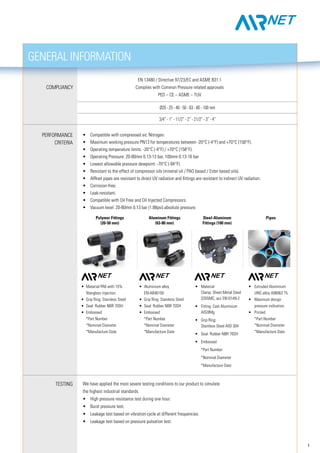
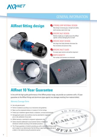
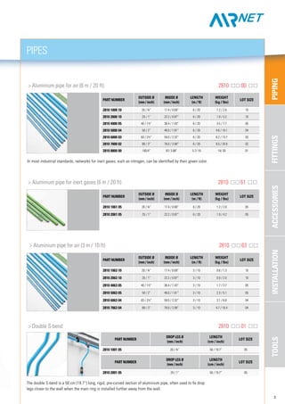
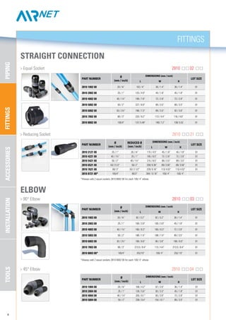
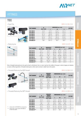
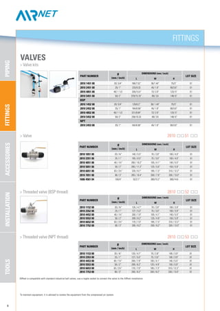
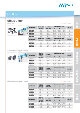
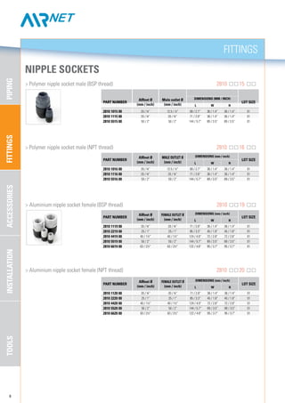
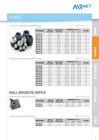
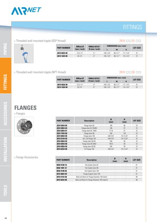
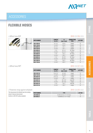


This document is a catalog listing piping, fittings, accessories, installation materials and tools from the company AIRnet-system. It includes: 1) Piping comes in aluminum, polymer coated aluminum, and green aluminum for inert gases, in sizes from 20-100mm. 2) Fittings include straight connectors, elbows, tees, valves, reducers, flanges and flexible hoses. 3) Accessories include end caps, hangers, gauges and unions. 4) Installation materials include brackets, clips and supports to install the piping system. 5) A range of tools and toolboxes are also listed for working on the piping system.


