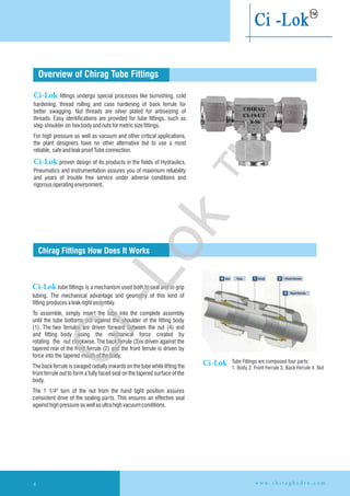
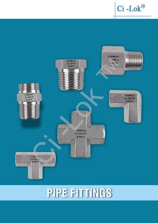
Tube Fittings
Needle Valves
Manifold Valves
Monoflange Valves
Ball Valves
Pipe Fittings
Master in Advance Technology to Control
(An ISO 9001:2008 Certified Company)
Needle Valves Screwed Bonnet
(Female X Female) . . . . . . . . . . . . . . . . . 42
Needle Valves Screwed Bonnet
(Male X Female) . . . . . . . . . . . . . . . . . . . 43
Panel Mount Needle Valves
Screwed Ends (Female X Female) . . . . . . 44
Needle Valves Screwed Bonnet Double
Ferrule Tube Ends (Tube X Tube) . . . . . . . 45
Needle Valves Screwed Bonnet
(Male X Male) . . . . . . . . . . . . . . . . . . . . . 46
Angle Needle Valve Screwed Bonnet
(Female X Female) . . . . . . . . . . . . . . . . . 47
Needle Valves Single Bonnet
(Female X Female) . . . . . . . . . . . . . . . . . 48
Needle Valves Single Bonnet
(Male X Female) . . . . . . . . . . . . . . . . . . . 49
Needle Valves 37
Two Valve Manifold
Multi-port Valve. . . . . . . . . . . . . . . . . . . . 53
Single Block & Bleed Valve . . . . . . . . . . . 54
Double Block & Bleed Valve. . . . . . . . . . . 55
Two Valve (three-way) Manifold
for Pressure Instruments. . . . . . . . . . . . . 56
Two Valve Manifold Remote Mount
(Pipe X Pipe) . . . . . . . . . . . . . . . . . . . . . 57
Two Valve “T” Type Manifold for
Pressure Instruments (Pipe X Flange) . . . 58
Three Valve Manifold
Three Valve Manifold Remote Mount
(Pipe X Pipe). . . . . . . . . . . . . . . . . . . . . . 60
Three Valve Manifold Bar Type
Direct Mount (Pipe X Flange) . . . . . . . . . 61
Three Valve Manifold Direct Mount
T Type (Pipe X Flange). . . . . . . . . . . . . . . 62
Three Valve Manifold Direct Mount
H Type (Flange X Flange). . . . . . . . . . . . . 63
Coplanar Mounting Three Valve Manifold
with Drain Plugs (Pipe X Flange) . . . . . . . 64
Five Valve Manifold
Five Valve Manifold Remote Mount
(Pipe X Pipe). . . . . . . . . . . . . . . . . . . . . . 65
Five Valve Manifold Bar Type Direct Mount
(Pipe X Flange) . . . . . . . . . . . . . . . . . . . . 67
Five Valve Manifold, Direct Mount
T Type (Pipe X Flange). . . . . . . . . . . . . . . 68
Five Valve Manifold Direct Mount
H Type (Flange X Flange). . . . . . . . . . . . . 69
Five Valve Manifold Coplanar Mount
(Pipe X Flange) . . . . . . . . . . . . . . . . . . . . 70
Manifold Valves 51
Monoflange Valves
Monoflange Single Isolation Valve. . . . 75
Monoflange Block & Bleed Valve . . . . 76
Monoflange DBB Valves . . . . . . . . . . . 77
Key Block DBB Valves . . . . . . . . . . . . 79-80
Gate Valves
Gate Valve (Socket Weld Ends). . . . . . 82
Gate Valve (Flange X Flange) . . . . . . . 83
Globe Valve (OS & Y Type) . . . . . . . . . 84
73Monoflange Valves
Mini Ball Valve . . . . . . . . . . . . . . . . . . 87
Round Body Ball Valve . . . . . . . . . . . . 88
Square Ball Valve . . . . . . . . . . . . . . . . 89
High Pressure Ball Valve . . . . . . . . . . . 90
Square Ball Valve High Pressure . . . . . 91
Panel Mount Ball Valve . . . . . . . . . . . . 92
2 Way Ball Valve. . . . . . . . . . . . . . . . . 93
3 Way Ball Valve. . . . . . . . . . . . . . . . . 94
5 Way Ball Valve. . . . . . . . . . . . . . . . . 95
85Ball Valves
Front Ferrule . . . . . . . . . . . . . . . . . . 13
Back Ferrule . . . . . . . . . . . . . . . . . . 13
Nuts . . . . . . . . . . . . . . . . . . . . . . . . 13
Male Connector . . . . . . . . . . . . . . . 14-15
Female Connector. . . . . . . . . . . . . . 16
Union . . . . . . . . . . . . . . . . . . . . . . . 17
Reducing Union . . . . . . . . . . . . . . . 18
Bulkhead Male Connector . . . . . . . . 19
Bulkhead Female Connector . . . . . . 20
Bulkhead Union. . . . . . . . . . . . . . . . 21
Bulkhead Reducing Union . . . . . . . . 22
Tube End Closure . . . . . . . . . . . . . . 22
Fitting End Closure . . . . . . . . . . . . . 23
Union Elbow . . . . . . . . . . . . . . . . . . 23
Male Elbow. . . . . . . . . . . . . . . . . . . 24-25
Female Elbow . . . . . . . . . . . . . . . . . 26
Male Adapter . . . . . . . . . . . . . . . . . 27
Union Cross . . . . . . . . . . . . . . . . . . 28
Union Tee . . . . . . . . . . . . . . . . . . . . 29
Reducing Union Tee . . . . . . . . . . . . 30
Bulkhead Elbow . . . . . . . . . . . . . . . 31
Male Run Tee . . . . . . . . . . . . . . . . . 32
Male Branch Tee . . . . . . . . . . . . . . . 33
Female Run Tee. . . . . . . . . . . . . . . . 34
Female Branch Tee . . . . . . . . . . . . . 35
Reducer . . . . . . . . . . . . . . . . . . . . . 36
11Double Ferrul Fittings
Plug . . . . . . . . . . . . . . . . . . . . . . . . . . 99
Bushing . . . . . . . . . . . . . . . . . . . . . . . 99
Nipple. . . . . . . . . . . . . . . . . . . . . . . . . 99
Cap . . . . . . . . . . . . . . . . . . . . . . . . . . 100
Coupling. . . . . . . . . . . . . . . . . . . . . . . 100
Adaptor . . . . . . . . . . . . . . . . . . . . . . . 100
Male Elbow. . . . . . . . . . . . . . . . . . . . . 101
Female Elbow . . . . . . . . . . . . . . . . . . . 101
Street Elbow. . . . . . . . . . . . . . . . . . . . 102
Male Tee. . . . . . . . . . . . . . . . . . . . . . . 102
Female Cross . . . . . . . . . . . . . . . . . . . 102
Female Tee . . . . . . . . . . . . . . . . . . . . . 103
Street Tee . . . . . . . . . . . . . . . . . . . . . . 104
Branch Tee . . . . . . . . . . . . . . . . . . . . . 104
97Pipe Fittings
Chirag Industries is an ISO 9001:2008 certified company, Involved in the manufacture of Valve Manifolds, Needle Valves,
Tube Fittings, Pipe Fittings, Ball Valves, Isolation Valves and Special Accessories used in Instrumentation, Hydraulics,
Pneumatics, which cater to oil & gas industries, petrochemicals, power generation, agro genic,
pharmaceuticals & vacuumapplications.
The company located in mumbai, started on a very small scale in 1995, is now having latest manufacturing & testing facilities. To
catertheengineersneedsoftheindustry..
About Us
Experience:
We offer a wide range of service to our clients, We are the one-stop for all your valves
& fittings solution; Our experience will help our customer to get the accurate desired
solutioneffectively.
Mission:
The mission of Chirag insdustries is committed to fulfill our customers
expectation by serving them appropriate products and very timely service.
Our vision is a long term commitment to the industry and our customers. which is
possible through our collective experience and our belief in honesty, integrity,
reliability, long- standingrelationshipsandtrust.
Vision:
The vision of company is based on its value of continuous innovation. undying
commitment and elaborate customer interaction. The company strives to provide the
best possible solution to the customer by listening and understanding the various
needsofthecustomer.
Quality:
Accredited with ISO 9001:2008 certification, Material are checked through approved
and authorised laboratories, with complete component tracebility and
documentation, following valve testing as per ANSI-B16.5 using test method by air,
hydrogenandhelium.
We have policy of continues improvement and are constantly focusing on ungrading
ourproductswithaviewtoenhancing theirperformance.
3w w w . c h i r a g h y d r o . c o m
Ci-Lok
™
Overview of Chirag Tube Fittings
Chirag Fittings How Does It Works
Ci-Lok tube fittings is a mechanism used both to seal and to grip
tubing. The mechanical advantage and geometry of this kind of
fitting producesaleak-tightassembly.
To assemble, simply insert the tube into the complete assembly
until the tube bottoms out against the shoulder of the fitting body
(1). The two ferrules are driven forward between the nut (4) and
and fitting body using the mechanical force created by
rotating the nut clockwise. The back ferrule (3)is driven against the
tapered rear of the front ferrule (2) and the front ferrule is driven by
force into the tapered mouthofthebody.
The back ferrule is swaged radially inwards on the tube while lifting the
front ferrule out to form a fully faced seal on the tapered surface of the
body.
The 1 1/4" turn of the nut from the hand tight position assures
consistent drive of the sealing parts. This ensures an effective seal
againsthighpressureaswellasultrahigh vacuumconditions.
Tube Fittings are composed four parts:
1. Body 2. Front Ferrule 3. Back Ferrule 4. Nut
Ci-Lok fittings undergo special processes like burnishing, cold
hardening, thread rolling and case hardening of back ferrule for
better swagging. Nut threads are silver plated for antiseizing of
threads. Easy identifications are provided for tube fittings, such as
step shoulder on hexbodyandnutsformetricsizefittings.
For high pressure as well as vacuum and other critical applications,
the plant designers have no other alternative but to use a most
reliable, safeandleakproofTubeconnection.
Ci-Lok proven design of its products in the fields of Hydraulics,
Pneumatics and Instrumentation assures you of maximum reliability
and years of trouble free service under adverse conditions and
rigorousoperatingenvironment.
CHIRAG
CI-19-UT
8-S6
w w w . c h i r a g h y d r o . c o m4
Ci-Lok
Ci-Lok
™
Chirag Fittings Installation Instructions
Before Installation
l UseaseamlessstainlesssteeltubewithbrightannealedfinishhavinghardnessofHv200orless.
l Usetubeasperrefer“tubing data”onpageNo-7.
l Forleakfreeconnectioncuttubewithtubecutter,thereshouldbenoscratchestill30mmonbothside.
l Iftubecutwithhacksawblate,itshouldberightangle.Removethesharpedgewithfileorgrander.
Insert the tube completely in to the Chirag fittings &
make sure that the front portion of the tube point
touch the shoulder of fitting body & nut is hand tight.
Make a mark on body of nut because that mark will help
as an indicator forstatingpoint.
Tighten the nut with the help of spanner as shown in fig.
(Image No. 2)
From the Figure A we can easily see that, for
the 11/4'' turn of the nut are required for 1/4''
(6 mm) and larger fittings.
From the Figure B we can see that, for
the 3/4'' turn of the nut is required for
3/16'' (4 mm ) and smaller fittings.
Reassembly Instruction
l Before reassembly the parts, ensure that there is no foreign particles on the sealing diagonal face of the fitting body and the front
ferrule.
l Insert the front ferrule until it reaches the body and then manually tighten the nut enough. With a wrench tighten the nut
approximately1/4turn.Assemblyiscomplete.
Notes: 1.Afterreassemblythefittingsbodyandnutshouldreturntotheiroriginalposition,orbetightened slightlyfurther.
2.Forfittingswithnominaldiameterbetween1.6mm(1/16''OD)and4mm,tighten thenut1/6turn.
3. For fittings with nominal diameter of 15.88 mm (5/8'' OD) or larger, it may occasionally be necessary to tighten the nut
1/4turnormore.
Figure A Figure B
Image No. 1 Image No. 2
5w w w . c h i r a g h y d r o . c o m
Ci-Lok
™
Physical Differences And Marking
Metric Fittings:
Tee & Elbow (see Fig.1)
Body marked: Shoulder
Straight Connectors: (see Fig. 2)
Body: Stepped shoulder
Marked: Chirag CI-14-UE-12m-S6
Nut: (see Figs.1 & 2) Stepped
shoulder Marked: Chirag SS316 12m
INCH FITTINGS:
Tee & Elbow: (see Fig.3)
Straight Fittings: (see Fig. 4)
Body: Shoulder
Marked: Chirag CI-14-UE-S6
Nut: (See Fig. 3 & 4) Shoulder
Marked: Chirag SS316
1/2"OD
Fig. 1 Front Side
Chirag SS316 12m
Fig. 2
Chirag
CI-6-UE
12m-S6
Chirag SS316 12m
Chirag
CI-14-UE
12m-S6
Stepped Shoulder
Fig. 3 Front side
Chirag SS316 1/2"OD
Fig. 4
Chirag
CI-6-U
8-S6
Chirag SS316 1/2" OD
Chirag
CI-14-UE
8-S6
CHIRAG
CI-14-UE
8-S6
CHIRAG
CI-14-UE
8-S6
w w w . c h i r a g h y d r o . c o m6
Ci-Lok
™
1.BS4368:PartIV,1984
2.IS10103:1982
7w w w . c h i r a g h y d r o . c o m
MaterialsStandards:
Fittings aremanufacturedinMaterials
316 Stainless ASTM A-276 ASME SA-479
Steel ASTM A-182 ASME SA-182
304 Stainless ASTM A-276 ASME SA-479
Steel ASTM A-182 ASME SA-182
Alloy 20 ASTM B-473 ASTM B-462
Alloy 400 ASTM B 164 ASME SB 164
ASTM B-564 ASME SB-564
Alloy C-276 ASTM B-574 ASTM B-564
Carbon Steel ASTM A-108 ASTM A-105
Materials Barstock Forgings
TubingSelection:
Selection of proper Tubing, their handling and installation is very
™
essential for use with Ci-Lok fittings. Proper selection of
Tubes based on the material, hardness, and wall thickness is
very important.
StainlessSteelTubing:
304 or 316 stainless steel tubing, cold-drawn seamless properly
annealed to ASTM A-269 or A-213 or equivalent based on Ultimate
Tensile strength of 75,000 psi and suitable for temperature between
20°Cto100°CShouldbeselected.
The hardness of the Tubes should normally be around RB 80-85
and preferably this should be in the range of RB 75-80. Tubes
should be suitable for bending and should be free from surface
defectsandimperfections.
MonelTubing:
Fully annealed Monel 400 seamless tubing to ASTM B-165 or
equivalent based on Ultimate Tensile strength of 70,000 psi and
suitablefortemperaturesbetween20°Cto90°Cshouldbeselected.
The hardness of the Tubes should normally be around RB 75 or less
Tube should be suitable for bending and should be free from surface
defectsandimperfections.
Technical Specificationsofthefittings:
There are no available standard specifications for Double ferrule
compression fittings. The following two standards which are
applicable to single compression fittings can be used for double
compressionfittingsalso
Dimensions:
# Dimensions, in inches (millimeters), are for reference
onlyandaresubjecttochange.
™
# Dimensionarewith Ci-lok Nutsfinger-tight.
Thread Specifications
NPT ASME 131.20.1, SAE AS,
71051
ISO/BSP(Parallel) ISO 228, BS 2779,
JIS B 0202
ISO/BSP(Tapered) ISO 7, BS 21,
JIS B 0203
ISO/BSP(Gauge) ISO 228, BS 2779,
Unified(SAE) ASME B1.1
Thread Type Ref. Specifications
ChiragModelNumberingandOrdering:
™
TheModelnumbersof Ci-Lok fittingsareestablishedasfollows:
Asmallletter‘m’followingthisnumberidentifiesthemmsize,e.g.4mdenotes4mmo/dsizeoftubes
If the first digit is not followed by ‘m’, the number denotes the o/d size in sixteenths of an inch,
e.g. 4 denotes 1 /4 "
th
Aswiththethreadsizesareexpressedin16 ofaninch,thusstudthreadsizesarebelow:
1/8"=2,1/4"=4,3/8"=6,1/2"=8
5/8"=10,3/4"=12,7/8"=14,1"=16
PleasestatewhetherNPT,BSPPorBSPTthreadsarerequired.
FororderinguseourModelNumbers.
A thread sealant or Teflon tape should always be used when
assemblingtaperedthreads.
All fitting components are cleaned to remove
machine oil grease and loose particles, using ultrasonic
clearing process. Specially made fittings are available in O2
Service.
Ci-lok
Ci-lok
Ci-Lok
™
PROOFPRESSURE TEST
Fitting assemblies are to be subjected to a pressure of 1.5 times the maximum working
pressure of the fittings applied at the rate of 200 Kg/cm² per minute and maintained at this
pressureforfiveminuteswithoutleak.
DISMANTLINGANDREASSEMBLETEST
Fitting assemblies successfully completing the Proof Pressure Test are dis-assembled
and assembled again twenty five times after which operation they must pass the Proof
PressureTest.
BURST PRESSURE TEST
Fitting assemblies are subjected to Hydraulic Pressure up to a maximum of four times
the working pressure at the rate not exceeding 200 Kg/cm² per minute and maintain for five
minuteswithoutleak.
STATICVACUUMTEST
Fitting assemblies satisfactorily Proof Pressure tested are subjected to negative pressure of
up to 700 mbar and then isolated from the vacuum source. The assemblies must maintain
the vacuum for 15 minutes. The fitting assemblies are to be suitably degreed before this test
andtotalexhaustedvolumeshouldnotexceed20%ofthetotalassemblyvolume.
IMPULSEVIBRATIONTEST
Test assemblies suitably proof pressure tested are connected to a Hydraulic Pressure
impulse and vibration test bench and subjected simultaneously to Pressure impulse at 30 to
100 cycles per minute and vibration in two mutually perpendicular planes at 1300 to 2820
O
cycles per minute for a minimum of 5x10 pressure impulses and 20x10 vibration cycles.
The method of choosing the displacement and the cycle is outlined in the above standards.
The only permissible retightening is allowed after the first 1,000 pressure impulses to allow
for bedding-in. When subjected to the test described, this coupling should not leak in the
assembly.Couplingsthatfailshallbeexaminedforsignsofcrackingduetofatiguestress.
PIPE END PRESSURE RATINGS
Pressure ratings for fittings that have both Tube fitting and Pipe thread ends are determined
by the end connections with the lowest Pressure rating. The Pipe End Pressure rating charts
lists the pressure rating for male and female pipe thread ends. For female and male pipe
threads to have the same pressure rating in the same nominal pipe size. The female thread
wouldrequireaheavierwall,resultinginafitting toolargeandbulkytobepractical.
O
These standards cover the basic test requirements for Fittings as indicated below:
w w w . c h i r a g h y d r o . c o m8
Ci-Lok
™
Tube Wall
Thickness than 0.012 than 0.014 than 0.016 than 0.020 than 0.028 than 0.035 than 0.049 than 0.065 than 0.083 than 0.095 than 0.109 than 0.120 0.120
mm inch
0.010-less 0.012-less 0.014-less 0.016-less 0.020-less 0.028-less 0.035-less 0.049-less 0.065-less 0.083-less 0.095-less 0.109-less
1/16" 5600 6860 8150 9480 12080
2 1/8" 8550 10950
3 3/16" 5500 7100 10300
6 1/4" 4100 5200 7600 10300
8 5/16" 4100 5900 8100
10 3/8" 3350 4850 6550
12 1/2" 2650 3750 5150 6750
16 5/8" 2950 4050 5250 6050
20 3/4" 2450 3350 4250 5250 5850
22 7/8" 2050 2850 3650 4250 4850
25 1" 2400 3100 3600 4200 4700
Table 1: Maximum allowable working pressure for wall thickness
Chirag Tubing Data
Table 2: Factors used to determine allowable working pressure at higher temperature
200 93 1
400 204 0.96
600 316 0.85
800 427 0.79
1000 538 0.76
1200 649 0.37
˚F ˚C A.I.S.I.316 To determine allowable pressure at higher temperatures,
multiply allowable working pressure from Table 1 by
factors shown in Table 2. For example: The allowable
pressure for Type 316 stainless steel, size 1/2" O.D. X
0.049" wall at 800˚F (427˚C) would be equivalent to
3750 psi X 0.79 = 2962.5 psi. Regarding min. nominal
wallthickness,pleaserefertoTable3.
Table 3: Gas Application Tubing
For gas applications, we recommend tubing with
a greater wall thickness. Table 3 shows the recommended
min.wallthicknessesforgreatersafetyandefficiency.
Tube OD Min. Nominal Tube OD Min. Nominal Wall
Wall Thickness Thickness
1/8" (3.17 mm) 0.028" (0.7 mm) 3 mm 0.8 mm
3/16" (4.76 mm) 0.028" (0.7 mm) 6 mm 0.8 mm
1/4" (6.35 mm) 0.028" (0.7 mm) 8 mm 1 mm
5/16" (7.93 mm) 0.035" (0.89 mm) 10 mm 1 mm
3/8" (9.52 mm) 0.035" (0.89 mm) 12 mm 1 mm
1/2" (12.7 mm) 0.049" (1.24 mm) 14 mm 1.2 mm
5/8" (15.87 mm) 0.065" (1.65 mm) 16 mm 1.5 mm
3/4" (19.05 mm) 0.065" (1.65 mm) 18 mm 1.5 mm
7/8" (22.22 mm) 0.083" (2.1 mm) 20 mm 1.8 mm
1" ( 25.4 mm) 0.083" (2.1 mm) 22 mm 2 mm
25 mm 2.2 mm
Note: 1) The value of Table 1 is a maximum allowable working pressure calculated from the tube thickness. The maximum
allowable working pressure of the fitting is limited from the value of this table according to the application regulations.
Pleaseuseit,afterconsideringtheapplicationregulationsandthestandardofusedequipment.
2)Thereisapossibilitythatthesealdecreasesremarkably,whenitisusedforalongtimeexceeding400˚C.
9w w w . c h i r a g h y d r o . c o m
Ci-Lok
™
Ci-Lok
™
TUBE FITTINGS
CHIRAG
CI-18-UC
8-S6
CHIRAG
CI-4-MC
8-8-S6-N
CHIRAG
CI-14-UE
8-S6
CHIRAG
CI-5-FC
8-8-S6-N
CHIRAG
CI-6-U
8-S6
CHIRAG
CI-10-BU
8-S6
CHIRAG
CI-19-UT
8-S6
Ci-Lok
™
Tube FittingsIndex
FRONT FERRULE BACK FERRULE NUTS
Page-15
UNION
Page-16
REDUCING UNION
TUBE END CLOSURE
Page-20
BULKHEAD REDUCING
UNION
Page-21
UNION ELBOW
Page-14
FEMALE CONNECTOR
Page-18
BULKHEAD FEMALE
CONNECTOR
Page-25
MALE ADAPTER
Page-28
REDUCING UNION TEE
Page-17
Page-24
FEMALE ELBOW
Page-19
BULKHEAD UNION
Page-20 Page-21
FITTING END CLOSURE
Page-27
UNION TEE
Page-29
BULKHEAD ELBOW
Page-11 Page-12 to 13
Page-32
FEMALE RUN TEE
Page-11 Page-11
BULKHEAD MALE
CONNECTOR
Page-22-23
MALE ELBOW
MALE CONNECTOR
UNION CROSS
Page-26
Page-31
MALE BRANCH TEE
Page-30
MALE RUN TEE
Page-33
FEMALE BRANCH TEE
w w w . c h i r a g h y d r o . c o m12
Page-34
Reducer
Ci-Lok
™
T
Front Ferrule
Back Ferrule
METRIC OD Tubes
Model No. T Tube OD
CI-3-N-3m
CI-3-N-6m 6
CI-3-N-8m 8
CI-3-N-10m 10
CI-3-N-12m 12
CI-3-N-14m 14
CI-3-N-15m 15
CI-3-N-16m 16
CI-3-N-18m 18
CI-3-N-20m 20
CI-3-N-22m 22
CI-3-N-25m 25
CI-3-N-28m 28
CI-3-N-30m 30
CI-3-N-32m 32
CI-3-N-38m 38
3
Model No. CI-1-FF
Model No. CI-2-BF
Model No. CI-3-N
INCH OD Tubes
Model No. T Tube OD
CI-1-FF-1
1/8
CI-1-FF-4 1/4
CI-1-FF-5 5/16
CI-1-FF-6 3/8
CI-1-FF-8 1/2
CI-1-FF-10 5/8
CI-1-FF-12 3/4
CI-1-FF-14 7/8
CI-1-FF-16 1
CI-1-FF-20 1.1/4
CI-1-FF-24 1.1/2
CI-1-FF-32 2
1/16
CI-1-FF-2
METRIC OD Tubes
Model No. T Tube OD
CI-1-FF-3m
CI-1-FF-6m 6
CI-1-FF-8m 8
CI-1-FF-10m 10
CI-1-FF-12m 12
CI-1-FF-14m 14
CI-1-FF-15m 15
CI-1-FF-16m 16
CI-1-FF-18m 18
CI-1-FF-20m 20
CI-1-FF-22m 22
CI-1-FF-25m 25
CI-1-FF-28m 28
CI-1-FF-30m 30
CI-1-FF-32m 32
CI-1-FF-38m 38
3
INCH OD Tubes
Model No. T Tube OD
CI-3-N-1
CI-3-N-2 1/8
CI-3-N-4 1/4
CI-3-N-5 5/16
CI-3-N-6 3/8
CI-3-N-8 1/2
CI-3-N-10 5/8
CI-3-N-12 3/4
CI-3-N-14 7/8
CI-3-N-16 1
CI-3-N-20 1.1/4
CI-3-N-24 1.1/2
CI-3-N-32 2
1/16
T
T
Note: All dimensions are subject to change without notice
All dimensions are in mm unless specified
Nut
INCH OD Tubes
Model No. T Tube OD
CI-2-BF- 1/16
CI-2-BF-2 1/8
CI-2-BF-4 1/4
CI-2-BF-5 5/16
CI-2-BF-6 3/8
CI-2-BF-8 1/2
CI-2-BF-10 5/8
CI-2-BF-12 3/4
CI-2-BF-14 7/8
CI-2-BF-16 1
CI-2-BF-20 1.1/4
CI-2-BF-24 1.1/2
CI-2-BF-32 2
1
METRIC OD Tubes
Model No. T Tube OD
3m 3
CI-2-BF-6m 6
CI-2-BF-8m 8
CI-2-BF-10m 10
CI-2-BF-12m 12
CI-2-BF-14m 14
CI-2-BF-15m 15
CI-2-BF-16m 16
CI-2-BF-18m 18
CI-2-BF-20m 20
CI-2-BF-22m 22
CI-2-BF-25m 25
CI-2-BF-28m 28
CI-2-BF-30m 30
CI-2-BF-32m 32
CI-2-BF-38m 38
CI-2-BF-
13w w w . c h i r a g h y d r o . c o m
Ci-Lok
™
1/16 1/16 23.9 9.6 11.0 8.6 1.3 8 8 20.0
CI-4-MC-1-2 1/16 1/8 26.2 9.6 11.0 8.6 1.3 11 8 22.4
CI-4-MC-2-2N 1/8 1/8 30.5 9.6 15.3 12.7 2.4 11 11 23.9
CI-4-MC-2-4N 1/8 1/4 35.6 14.3 15.3 12.7 2.4 14 11 29.0
CI-4-MC-4-2N 1/4 1/8 32.8 9.6 17.8 15.3 4.8 14 14 25.4
CI-4-MC-4-4N 1/4 1/4 37.8 14.3 17.8 15.3 4.8 14 14 30.5
CI-4-MC-4-6N 1/4 3/8 38.4 14.3 17.8 15.3 4.8 19 14 31.0
CI-4-MC-4-8N 1/4 1/2 44.7 19.1 17.8 15.3 4.8 22 14 37.4
CI-4-MC-5-4N 5/16 1/4 38.6 14.3 18.5 16.3 6.3 14 16 31.2
CI-4-MC-6-2N 3/8 1/8 35.3 9.6 19.3 16.8 4.8 16 17 27.9
CI-4-MC-6-4N 3/8 1/4 39.8 14.3 19.3 16.8 7.1 16 17 32.5
CI-4-MC-6-6N 3/8 3/8 39.8 14.3 19.3 16.8 7.1 19 17 32.5
CI-4-MC-6-8N 3/8 1/2 41.2 19.1 19.3 16.8 7.1 22 17 38.9
CI-4-MC-8-4N 1/2 1/4 43.4 14.3 21.8 22.9 7.1 22 22 33.3
CI-4-MC-8-6N 1/2 3/8 43.4 14.3 21.8 22.9 9.6 22 22 33.3
CI-4-MC-8-8N 1/2 1/2 49.0 19.1 21.8 22.9 10.4 22 22 38.9
CI-4-MC-8-12N 1/2 3/4 50.5 19.1 21.8 22.9 10.4 27 22 40.4
CI-4-MC-8-16N 1/2 1 57.1 23.8 21.8 22.9 10.4 35 22 47.0
CI-4-MC-10-6N 5/8 3/8 44.2 14.3 21.8 24.4 9.6 24 25 34.0
CI-4-MC-10-8N 5/8 1/2 49.0 19.1 21.8 24.4 10.4 24 25 38.9
CI-4-MC-12-8N 3/4 1/2 50.5 19.1 21.8 24.4 10.4 27 28.5 40.4
CI-4-MC-12-12N 3/4 3/4 50.5 19.1 21.8 24.4 15.8 27 28.5 40.4
CI-4-MC-12-16N 3/4 1 57.1 23.8 21.8 24.4 15.8 35 28.5 47.0
CI-4-MC-14-12N 7/8 3/4 50.5 19.1 21.8 26.0 15.8 30 32 40.4
CI-4-MC-16-8N 1 1/2 57.4 19.1 26.4 31.2 10.4 35 38 45.2
CI-4-MC-16-12N 1 3/4 57.4 19.1 26.4 31.2 15.8 35 38 45.2
CI-4-MC-16-16N 1 1 62.2 23.8 26.4 31.2 22.3 35 38 50.0
CI-4-MC-20-16N 1 1/4 1 77.2 23.8 38.9 41.2 22.3 46 50 55.2
CI-4-MC-20-20N 1 1/4 1 1/4 77.2 23.8 38.9 41.2 27.6 46 50 55.2
CI-4-MC-24-24N 1 1/2 1 1/2 88.9 26.2 45.2 50.0 34.0 55 57 61.7
CI-4-MC-32-32N 2 2 113.5 26.9 62.7 67.6 46.0 70 76 76.2
CI-4-MC-1-1N
N
T P
Model No. Tube NPT A B C D E F G H
OD Male min. A/F A/F
INCH OD Tubes X Male NPT Threads
Model No. CI-4-MCMale Connector
H
B
G
T
D
C
A
E
P
F
w w w . c h i r a g h y d r o . c o m14
Note: All dimensions are subject to change without notice
All dimensions are in mm unless specified
Ci-Lok
™
H
B
G
E
P
F
T
D
C
A
T P
Model No. Tube NPT A B C D E F G H
OD Male min. A/F A/F
3 1/8 30.5 9.6 15.3 12.9 2.4 11 11 23.9
3 1/4 35.6 14.3 15.3 12.9 2.4 14 11 29.0
CI-4-MC-6m-2N 6 1/8 32.8 9.6 17.7 15.3 4.8 14 14 25.4
CI-4-MC-6m-4N 6 1/4 37.9 14.3 17.7 15.3 4.8 14 14 30.5
CI-4-MC-6m-6N 6 3/8 38.4 14.3 17.7 15.3 4.8 19 14 31.0
CI-4-MC-6m-8N 6 1/2 44.7 19.1 17.7 15.3 4.8 22 14 37.3
CI-4-MC-8m-2N 8 1/8 34.2 9.6 18.6 16.2 4.8 14 16 26.7
CI-4-MC-8m-4N 8 1/4 38.7 14.3 18.6 16.2 6.3 14 16 31.2
CI-4-MC-8m-6N 8 3/8 39.3 14.3 18.6 16.2 6.3 19 16 31.8
CI-4-MC-8m-8N 8 1/2 45.6 19.1 18.6 16.2 6.3 22 16 38.1
CI-4-MC-10m-2N 10 1/8 36.3 9.6 19.5 17.2 4.8 17 19 28.7
CI-4-MC-10m-4N 10 1/4 40.9 14.3 19.5 17.2 7.9 19 19 33.3
CI-4-MC-10m-6N 10 3/8 40.9 14.3 19.5 17.2 7.9 19 19 33.3
CI-4-MC-10m-8N 10 1/2 46.5 19.1 19.5 17.2 7.9 22 19 38.9
CI-4-MC-12m-4N 12 1/4 43.4 14.3 22.0 22.8 7.1 22 22 33.3
CI-4-MC-12m-6N 12 3/8 43.4 14.3 22.0 22.8 9.5 22 22 33.3
CI-4-MC-12m-8N 12 1/2 49.0 19.1 22.0 22.8 9.5 22 22 38.9
CI-4-MC-12m-12N 12 3/4 50.5 19.1 22.0 22.8 9.5 27 22 40.4
CI-4-MC-12m-16N 12 1 57.1 23.8 22.0 22.8 9.5 35 22 47.0
CI-4-MC-14m-4N 14 1/4 44.1 14.3 22.0 24.4 7.1 24 25 34.0
CI-4-MC-14m-6N 14 3/8 44.1 14.3 22.0 24.4 9.5 24 25 34.0
CI-4-MC-14m-8N 14 1/2 49.0 19.1 22.0 24.4 11.1 24 25 38.9
CI-4-MC-15m-8N 15 1/2 49.0 19.1 22.0 24.4 11.9 24 25 38.9
CI-4-MC-16m-6N 16 3/8 44.1 14.3 22.0 24.4 9.5 24 25 34.0
CI-4-MC-16m-8N 16 1/2 49.0 19.1 22.0 24.4 11.9 24 25 38.9
CI-4-MC-16m-12N 16 3/4 50.5 19.1 22.0 24.4 12.7 27 25 40.4
CI-4-MC-18m-8N 18 1/2 50.5 19.1 22.0 24.4 11.9 27 30 40.4
CI-4-MC-18m-12N 18 3/4 50.5 19.1 22.0 24.4 15.1 27 30 40.4
CI-4-MC-20m-8N 20 1/2 52.3 19.1 22.0 26.0 11.9 30 32 42.2
CI-4-MC-20m-12N 20 3/4 52.3 19.1 22.0 26.0 15.9 30 32 42.2
CI-4-MC-22m-12N 22 3/4 52.3 19.1 22.0 26.0 15.9 30 32 42.2
CI-4-MC-22m-16N 22 1 57.1 23.8 22.0 26.0 18.3 35 32 47.0
CI-4-MC-25m-8N 25 1/2 57.5 19.1 26.5 31.3 11.9 35 38 45.2
CI-4-MC-25m-12N 25 3/4 57.5 19.1 26.5 31.3 15.8 35 38 4 5.2
CI-4-MC-25m-16N 25 1 62.3 23.8 26.5 31.3 21.8 35 38 50.0
CI-4-MC-28m-16N 28 1 72.4 23.8 36.6 36.6 21.8 41 46 51.6
CI-4-MC-28m-20N 28 1.1/4 73.1 23.8 36.6 36.6 21.8 46 46 52.3
CI-4-MC-30m-20N 30 1.1/4 77.2 23.8 39.2 39.6 26.2 46 50 55.6
CI-4-MC-32m-20N 32 1.1/4 79.6 23.8 41.6 42.0 28.6 46 50 56.6
CI-4-MC-38m-24N 38 1.1/2 96.6 26.2 47.9 49.4 33.7 55 57 64.0
CI-4-MC-3m-4N
CI-4-MC-3m-2N
METRIC OD Tubes x Male NPT Threads
Model No. CI-4-MCMale Connector
15w w w . c h i r a g h y d r o . c o m
Note: All dimensions are subject to change without notice
All dimensions are in mm unless specified
Ci-Lok
™
T P
Model No. Tube NPT A B C D E F G H
OD Female min. A/F A/F
INCH OD Tubes x Female NPT Threads
CI-5-FC-3m-4N 3 1 /4 35.3 12.9 15.3 12.9 2.4 20.5 1 1 28.7
CI-5-FC-6m-4N 6 1 /4 37.6 12.9 17.7 15.3 4.8 20.5 14 30.2
CI-5-FC-6m-6N 6 3/8 37.6 14.1 17.7 15.3 4.8 22 14 30.2
CI-5-FC-6m-8N 6 1 /2 43.5 18.9 17.7 15.3 4.8 25 14 36.1
CI-5-FC-8m-4N 8 1 /4 38.5 12.9 18.6 16.2 5.5 20.5 16 31.0
CI-5-FC-8m-6N 8 3/8 36.2 14.1 18.6 16.2 6.5 22 16 28.7
CI-5-FC-8m-8N 8 1 /2 41.0 18.9 18.6 16.2 7.1 25 16 33.5
CI-5-FC-10m-4N 10 1 /4 39.4 19.5 19.5 17.2 5.5 20.5 19 31.8
CI-5-FC-10m-6N 10 3/8 38.8 19.5 19.5 17.2 6.5 22 19 31.2
CI-5-FC-10m-8N 10 1 /2 42.1 19.5 19.5 17.2 7.1 25 19 34.5
CI-5-FC-12m-4N 12 1 /4 41.9 12.9 22.0 22.8 5.5 20.5 22 31.8
CI-5-FC-12m-6N 12 3/8 44.4 14.1 22.0 22.8 6.5 22 22 34.3
CI-5-FC-12m-8N 12 1 /2 48.2 18.9 22.0 22.8 7.1 25 22 38.1
T P
Model No. Tube NPT A B C D E F G H
OD Female min. A/F A/F A/F
METRIC OD Tubes x Female NPT Threads
Model No. CI-5-FCFemale Connector
1/16 1/16 23.6 9.9 11.0 8.6 1.3 11 8 19.8
CI-5-FC-1-2N 1/16 18 24.4 10.4 11.0 8.6 1.3 14 8 20.6
CI-5-FC-2-2N 1/8 1/8 28.7 10.4 15.3 12.7 2.4 14 11 22.1
CI-5-FC-2-4N 1/8 1/4 33.6 15.0 15.3 12.7 2.4 20.5 11 26.9
CI-5-FC-4-2N 1/4 1/8 31.2 9.9 17.8 15.3 4.8 14 14 23.9
CI-5-FC-4-4N 1/4 1/4 35.8 15.0 17.8 15.3 4.8 20.5 14 28.5
CI-5-FC-4-6N 1/4 3/8 37.6 15.0 17.8 15.3 4.8 22 14 30.2
CI-5-FC-4-8N 1/4 1/2 42.4 19.8 17.8 15.3 4.8 25 14 35.0
CI-5-FC-5-2N 5/16 1/8 32.0 10.4 18.5 16.3 6.3 14 16 24.6
CI-5-FC-5-4N 5/16 1/4 36.8 15.0 18.5 16.3 6.3 20.5 16 29.5
CI-5-FC-6-2N 3/8 1/8 32.8 10.4 19.3 16.8 7.1 16 17 25.4
CI-5-FC-6-4N 3/8 1/4 37.6 15.0 19.3 16.8 7.1 20.5 17 30.2
CI-5-FC-6-6N 3/8 3/8 39.1 15.0 19.3 16.8 7.1 22 17 31.8
CI-5-FC-6-8N 3/8 1/2 43.9 19.8 19.3 16.8 7.1 25 17 36.6
CI-5-FC-8-4N 1/2 1/4 40.4 15.0 21.8 22.9 10.4 20.5 22 30.2
CI-5-FC-8-6N 1/2 3/8 41.9 15.0 21.8 22.9 10.4 22 22 30.2
CI-5-FC-8-8N 1/2 1/2 46.7 19.8 21.8 22.9 10.4 25 22 36.6
CI-5-FC-8-12N 1/2 3/4 48.3 20.6 21.8 22.9 10.4 32 22 38.1
CI-5-FC-10-6N 5/8 3/8 41.9 15.0 21.8 24.4 12.7 22 25 31.8
CI-5-FC-10-8N 5/8 1/2 46.7 19.8 21.8 24.4 12.7 25 25 36.6
CI-5-FC-12-8N 3/4 1/2 46.7 19.8 21.8 24.4 15.8 25 28.5 36.6
CI-5-FC-12-12N 3/4 3/4 48.3 20.6 21.8 24.4 15.8 35 28.5 38.1
CI-5-FC-14-12N 7/8 3/4 49.8 20.6 21.8 25.9 18.3 35 32 39.6
CI-5-FC-16-12N 1 3/4 53.4 20.6 26.4 31.2 22.3 35 38 41.2
CI-5-FC-16-16N 1 1 62.3 25.4 26.4 31.2 22.3 41 38 50.0
CI-5-FC-20-20N 1 1/4 1 1/4 74.6 25.4 38.9 41.2 27.6 55 50 52.6
CI-5-FC-24-24N 1 1/2 1 1/2 83.3 27.6 45.2 50.0 34.0 60 60 56.2
CI-5-FC-1-1NH
B
G
T
E
P
F
D
C
A
w w w . c h i r a g h y d r o . c o m16
Note: All dimensions are subject to change without notice
All dimensions are in mm unless specified
Ci-Lok
™
1/16 25.1 11.0 8.6 1.3 8 8 17.5
CI-6-U-2 1/8 35.6 15.3 12.7 2.4 11 11 22.4
CI-6-U-4 1/4 40.9 17.8 15.3 4.8 14 14 26.2
CI-6-U-5 5/16 42.9 18.5 16.3 6.3 14 16 28.2
CI-6-U-6 3/8 45.0 19.3 16.8 7.1 16 17 30.2
CI-6-U-8 1/2 51.3 21.8 22.9 10.4 20.5 22 31.0
CI-6-U-10 5/8 52.0 21.8 24.4 12.7 24 25 31.8
CI-6-U-12 3/4 53.6 21.8 24.4 15.8 27 28.5 33.3
CI-6-U-14 7/8 55.2 21.8 25.9 18.2 30 32 34.8
CI-6-U-16 1 64.8 26.4 31.2 22.3 35 38 40.4
CI-6-U-20 1 1/4 92.2 38.9 41.2 27.6 46 50 48.0
CI-6-U-24 1 1/2 108.0 45.2 50.0 34.0 55 57 53.6
CI-6-U-32 2 149.4 62.7 67.6 46.0 70 76 74.7
CI-6-U-1
Union
INCH OD Tubes
T
Model No. Tube A C D E F G H
OD min. A/F A/F
METRIC OD Tubes
T
Model No. Tube A C D E F G H
OD min. A/F A/F
Model No. CI-6-U
3m 3 35.3 15.3 12.9 2.4 11 11 22.1
CI-6-U-6m 6 41.0 17.7 15.3 4.8 14 14 26.2
CI-6-U-8m 8 43.2 18.6 16.2 6.3 16 16 28.2
CI-6-U-10m 10 46.2 19.5 17.2 7.9 17 19 31.0
CI-6-U-12m 12 51.2 22.0 22.8 9.5 20.5 22 31.0
CI-6-U-14m 14 52.0 22.0 24.4 11.1 24 25 31.0
CI-6-U-15m 15 52.0 22.0 24.4 11.9 24 25 31.8
CI-6-U-16m 16 52.0 22.0 24.4 12.7 24 25 31.8
CI-6-U-18m 18 53.5 22.0 24.4 15.1 27 30 33.3
CI-6-U-20m 20 55.0 22.0 26.0 15.9 30 32 34.8
CI-6-U-22m 22 55.0 22.0 26.0 18.3 30 32 34.8
CI-6-U-25m 25 65.0 26.5 31.3 21.8 35 38 40.4
CI-6-U-28m 28 85.0 36.6 36.6 21.8 41 46 43.4
CI-6-U-30m 30 92.7 39.2 39.6 26.2 46 50 49.5
CI-6-U-32m 32 97.3 41.6 42.0 28.6 46 50 51.3
CI-6-U-38m 38 113.6 47.9 49.4 33.7 55 57 58.4
CI-6-U-
A
H
F
G E G
D
C
D
C
T
T
17w w w . c h i r a g h y d r o . c o m
Note: All dimensions are subject to change without notice
All dimensions are in mm unless specified
Ci-Lok
™
Reducing Union
1/4 1/8 38.6 17.8 15.3 15.3 12.7 2.4 14 14 11 24.6
CI-7-RU-5-2 5/1 1/8 39.6 18.6 15.3 16.3 12.7 2.4 14 16 11 25.7
CI-7-RU-5-4 5/16 1/4 42.2 18.6 17.8 16.3 15.3 4.8 14 16 14 27.5
CI-7-RU-6-2 3/ 8 1/8 40.9 19.3 15.3 16.8 12.7 2.4 16 17 11 26.9
CI-7-RU-6-4 3/ 8 1/4 43.2 19.3 17.8 16.8 15.3 4.8 16 17 14 28.5
CI-7-RU-8-2 1/ 2 1/8 45.2 21.8 15.3 22.9 12.7 2.4 20.5 22 11 28.5
CI-7-RU-8-4 1/ 2 1/4 47.0 1.8 17.8 22.9 15.3 4.8 20.5 22 14 29.5
CI-7-RU-8-6 1/ 2 3/8 48.5 21.8 19.3 22.9 16.8 7.1 20.5 22 17 31.0
CI-7-RU-10-6 5/8 3/8 49.3 21.8 19.3 24.4 16.8 7.1 24 25 17 31.8
CI-7-RU-10-8 5/ 8 1/2 52.0 21.8 21.8 24.4 22.9 10.4 24 25 22 31.8
CI-7-RU-12-4 3/ 4 1/4 49.3 21.8 17.8 24.4 15.3 4.8 27 28.5 14 31.8
CI-7-RU-12-6 3/ 4 3/8 50.8 21.8 19.3 24.4 16.8 7.1 27 28.5 17 33.3
CI-7-RU-12-8 3/ 4 1/2 53.6 21.8 21.8 24.4 22.9 10.4 27 28.5 22 33.3
CI-7-RU-16-8 1 1/2 60.5 26.5 21.8 31.2 22.9 10.4 35 38 22 38.1
CI-7-RU-16-12 1 3/4 60.5 26.5 21.8 31.2 24.4 15.8 35 38 28.5 38.1
CI-7-RU-20-16 1 1/4 1 92.2 38.9 26.4 41.2 3 1.2 22.3 45 50 38 48.0
CI-7-RU-24-20 1 1/2 1 1/4 60.5 26.5 21.8 31.2 24.4 15.8 55 57 50 53.6
CI-7-RU-4-2
6
T Tx
Model No. Tube Tube A C Cx D Dx E F G Gx H
OD OD min. A/F A/F A/F
T Tx
Model No. Tube Tube A C Cx D Dx E F G Gx H
OD OD min. A/F A/F A/F
METRIC OD Tubes
H
F
G
E
Tx
Gx
D
C
Dx
Cx
A
T
INCH OD Tubes
Model No. CI-7-RU
6 3 38.6 17.7 15.3 15.3 12.9 2.4 14 14 11 24.6
CI-7-RU-8m-6m 8 6 42.3 18.6 17.7 16.2 15.3 4.8 14 16 14 27.4
CI-7-RU-10m-6m 10 6 44.5 19.5 17.7 17.2 15.3 4.8 17 19 14 29.5
CI-7-RU-10m-8m 10 8 45.1 19.5 18.6 17.2 16.2 6.3 17 19 16 30.0
CI-7-RU-12m-6m 12 6 47.0 22.0 17.7 22.8 15.3 4.8 20.5 22 14 29.5
CI-7-RU-12m-8m 12 8 47.8 22.0 18.6 22.8 16.2 6.4 20.5 22 16 30.2
CI-7-RU-12m-10m 12 10 48.7 22.0 19.5 22.8 17.2 7.9 20.5 22 19 31.0
CI-7-RU-16m-10m 16 10 49.5 22.0 19.5 24.4 17.2 7.9 24 25 19 31.8
CI-7-RU-16m-12m 16 12 52.0 22.0 22.0 24.4 22.8 9.5 24 25 22 31.8
CI-7-RU-22m-18m 22 18 55.0 22.0 22.0 26.0 24.4 15.1 30 32 30 34.8
CI-7-RU-22m-20m 22 20 55.0 22.0 22.0 26.0 26.6 15.9 30 32 32 34.8
CI-7-RU-25m-12m 25 12 65.0 26.5 22.0 31.3 22.8 9.5 35 38 22 40.4
CI-7-RU-25m-20m 25 20 65.0 26.5 22.0 31.3 26.0 15.9 35 38 32 40.4
CI-7-RU-30m-20m 30 20 75.4 39.2 22.0 39.6 26.0 15.9 45 50 32 43.7
CI-7-RU-30m-25m 30 25 80.1 39.2 26.5 39.6 31.3 21.8 45 50 38 46.2
CI-7-RU-32m-20m 32 20 77.8 41.6 22.0 42.0 26.0 15.9 45 50 32 44.7
CI-7-RU-32m-25m 32 25 82.3 41.6 26.5 42.0 31.3 21.8 45 50 38 47.0
CI-7-RU-38m-20m 38 20 92.0 47.9 26.5 49.4 31.3 21.8 55 57 38 52.1
CI-7-RU-38m-25m 38 25 104.6 47.9 39.2 49.4 39.6 26.2 55 57 50 55.4
CI-7-RU-6m-3m
w w w . c h i r a g h y d r o . c o m18
Note: All dimensions are subject to change without notice
All dimensions are in mm unless specified
Ci-Lok
™
INCH OD Tubes x Male NPT Threads
METRIC OD Tubes x Male NPT Threads
Bulkhead Male Connector
CI-8-BMC-2-2N 1/8 1/8 46.4 31.2 9.6 12.7 2.4 14 11 39.8 24.6 8.3 12.7
CI-8-BMC-4-2N 1/4 1/8 49.5 33.5 9.6 15.3 4.8 16 14 42.2 26.2 11.5 10.2
CI-8-BMC-4-4N 1/4 1/4 54.1 33.5 14.3 15.3 4.8 16 14 46.7 26.2 11.5 10.2
CI-8-BMC-6-4N 3/8 1/4 57.4 36.8 14.3 16.8 7.1 19 17 50.0 29.5 14.7 11.2
CI-8-BMC-6-6N 3/8 3/8 57.4 36.8 14.3 16.8 7.1 19 17 50.0 29.5 14.7 11.2
CI-8-BMC-6-8N 3/8 1/2 63.7 36.8 19.1 16.8 7.1 22 17 56.5 29.5 14.7 11.2
CI-8-BMC-8-6N 1/2 3/8 63.3 41.9 14.3 22.9 9.6 24 22 53.0 31.8 19.5 12.7
CI-8-BMC-8-8N 1/2 1/2 68.8 41.9 19.1 22.9 10.4 24 22 58.8 31.8 19.5 12.7
CI-8-BMC-12-12N 3/4 3/4 76.2 47.5 19.1 24.4 15.8 30 28.5 66.9 37.4 25.8 16.8
CI-8-BMC-16-16N 1 1 93.2 57.4 23.9 31.2 22.3 41 38 81.0 45.2 33.7 19.0
CI- 8-BMC-20-20N 1 1/4 1 1/4 110.5 72.5 23.9 41.2 27.6 50 50 87.5 49.5 42.5 19.0
CI- 8-BMC-24-24N 1 1/2 1 1/2 122.8 79.1 26.2 50.0 34.0 60 57 95.5 51.5 50.5 19.0
T P Panel Max.
Model No. Tube NPT A Ax B D E F G H Hx Hole Panel
OD Male min. A/F A/F Drill Thick-
Size ness
Model No. CI-8-BMC
CI-8-BMC-3m-2N 3 1/8 46.4 31.2 9.6 12.9 2.4 11 11 39.8 24.6 8.3 12.7
CI-8-BMC-6m-2N 6 1/8 49.5 33.5 9.6 15.3 4.8 16 14 42.2 24.2 11.5 10.2
CI-8-BMC-10m-4N 10 1/4 57.4 36.8 14.3 17.2 7.1 19 17 50.0 29.5 14.7 11.2
CI-8-BMC-10m-4N 10 3/8 57.4 36.8 14.3 17.2 7.1 19 17 50.0 29.5 14.7 11.2
CI-8-BMC-12m-6N 12 3/8 63.3 41.9 14.3 22.0 9.6 24 22 53.0 31.8 19.5 12.7
CI-8-BMC-12m-8N 12 1/2 68.8 41.9 19.1 22.0 10.4 24 22 58.8 31.8 19.5 12.7
CI-8-BMC-16m-8N 16 1/2 69.6 42.6 19.1 24.4 11.9 27 25 59.5 32.5 22.8 12.7
CI-8-BMC-22m-12N 22 3/4 83.3 53.0 19.1 26.0 15.8 35 25 73.2 42.9 29.0 19.0
CI-8-BMC-25m-16N 25 1 93.2 57.4 23.9 31.3 22.3 41 38 81.0 45.2 33.7 19.0
CI- 8-BMC-32m-20N 32 1 1/4 110.5 72.5 23.9 42.0 28.6 50 50 87.5 49.5 42.5 19.0
CI- 8-BMC-38m-24N 38 1 1/2 122.8 79.1 26.2 49.4 33.7 60 57 95.5 51.5 50.5 19.0
T P Panel Max.
Model No. Tube NPT A Ax B D E F G H Hx Hole Panel
OD Male min. A/F A/F Drill Thick-
Size ness
H
HxB
G
T
Fx
E
P
F
D
Ax
A
19w w w . c h i r a g h y d r o . c o m
Note: All dimensions are subject to change without notice
All dimensions are in mm unless specified
Ci-Lok
™
Metric OD Tubes x Female NPT Threads
INCH OD Tubes x Female NPT Threads
Bulkhead Female Connector Model No. CI-9-BFC
CI-9-BFC-2-2N 1/8 1/8 44.7 31.2 10.4 12.7 2.4 14 11 38.1 24.6 8.3 12.7
CI-9-BFC-4-2N 1/4 1/8 47.0 33.5 10.4 15.3 4.8 16 14 39.7 26.2 11.5 10.2
CI-9-BFC-4-4N 1/4 1/4 51.5 33.5 15.0 15.3 4.8 20.5 14 44.2 26.2 11.5 10.2
CI-9-BFC-6-4N 3/8 1/4 54.8 36.8 15.0 16.8 7.1 20.5 17 47.5 29.5 14.7 11.2
CI-9-BFC-8-6N 1/2 3/8 61.7 41.9 15.0 22.9 10.4 22 22 51.6 31.0 19.5 12.7
CI-9-BFC-8-8N 1/2 1/2 66.7 41.9 19.8 22.9 10.4 25 22 56.6 31.0 19.5 12.7
CI-9-BFC-10-8N 5/8 1/2 67.6 42.7 19.8 22.9 12.7 25 25 57.4 32.5 22.6 12.7
CI-9-BFC-12-8N 3/4 1/2 72.4 47.5 19.8 24.4 16.0 35 28.5 62.3 37.4 25.8 16.8
CI-9-BFC-12-12N 3/4 3/4 74.7 47.5 20.6 24.4 16.0 35 28.5 64.3 37.4 25.8 16.8
CI-9-BFC-16-12N 1 3/4 84.3 57.4 20.6 31.2 16.0 35 38 72.1 45.2 33.7 19.0
CI-9-BFC-16-16N 1 1 93.2 57.4 25.4 31.2 22.2 35 38 81.0 45.2 33.7 19.0
CI-9-BFC-20-20N 1.1/4 1.1/4 105.7 69.9 25.4 41.2 27.6 50 50 83.5 47.7 41.6 19.0
CI-9-BFC-24-24N 1.1/2 1.1/2 144.5 76.4 27.6 50.0 34.0 60 57 87.4 49.3 49.6 19.0
T P Panel Max.
Model No. Tube NPT A Ax B D E F G H Hx Hole Panel
OD Female min. A/F A/F Drill Thick-
Size ness
3 1/8 44.7 31.2 10.4 12.9 2.4 14 11 38.1 24.6 8.3 12.7
CI-9-BFC-6m-4N 6 1/4 51.6 33.6 15.0 15.3 4.8 20.5 14 44.2 26.2 11.5 10.2
CI-9-BFC-10m-4N 10 3/8 56.8 37.0 15.0 17.2 7.9 22 19 49.2 29.4 16.3 11.2
CI-9-BFC-12m-6N 12 3/8 61.8 41.9 15.0 22.8 9.5 22 22 51.7 31.8 19.5 12.7
CI-9-BFC-12m-8N 12 1/2 66.7 41.9 19.8 22.8 9.5 25 22 56.6 31.8 19.5 12.7
CI-9-BFC-16m-8N 16 1/2 67.5 42.6 20.6 24.4 12.7 25 25 57.4 32.5 22.8 12.7
CI-9-BFC-22m-12N 22 3/4 79.9 53.0 20.6 26.0 15.8 35 35 69.8 42.9 29.0 19.0
CI-9-BFC-25m-12N 25 3/4 84.3 57.4 20.6 31.2 15.8 35 38 72.1 45.2 33.7 19.0
CI-9-BFC-25m-16N 25 1 93.2 57.4 25.4 31.2 22.3 35 38 81.0 45.2 33.7 19.0
CI-9-BFC-32m-20N 32 1.1/4 105.7 69.9 25.4 42.0 27.6 50 50 83.5 44.7 41.6 19.0
CI-9-BFC-38m-24N 38 1.1/2 114.5 76.4 27.6 49.4 33.7 60 57 87.4 49.3 49.6 19.0
T P Panel Max.
Model No. Tube NPT A Ax B D E F G H Hx Hole Panel
OD Female min. A/F A/F Drill Thick-
Size ness
CI-9-BFC-3m-2N
H
HxB
G
T
F
E
P
F
D
Ax
A
w w w . c h i r a g h y d r o . c o m20
Note: All dimensions are subject to change without notice
All dimensions are in mm unless specified
Ci-Lok
™
INCH OD Tubes
Bulkhead Union
METRIC OD Tubes
Model No. CI-10-BU
CI-10-BU-1 1/16 31.5 17.3 11.0 8.6 1.3 11 8 23.8 13.5 5.2 3.0
CI-10-BU-2 1/8 51.3 31.2 15.3 12.7 2.4 11 11 38.1 24.6 8.3 12.7
CI-10-BU-4 1/4 57.6 33.6 17.8 15.3 4.8 16 14 43.0 26.2 11.5 10.1
CI-10-BU-5 5/16 60.7 35.8 18.5 16.3 6.3 17 16 46.0 28.5 13.0 11.1
CI-10-BU-6 3/8 62.2 36.8 19.3 7.1 7.1 22 17 47.5 29.5 14.6 11.1
CI-10-BU-8 1/2 71.1 41.9 21.8 22.9 10.4 24 22 50.8 31.8 19.5 12.7
CI-10-BU-10 5/8 72.6 42.7 21.8 24.4 12.7 27 25 52.3 32.5 22.6 12.7
CI-10-BU-12 3/4 79.0 47.5 21.8 24.4 16.0 30 28.5 58.6 37.4 25.8 16.8
CI- 10-BU-16 1 95.6 57.4 26.4 31.2 22.3 35 38 71.3 45.2 33.7 19.0
CI-10-BU-20 1.1/4 123.2 69.9 38.9 41.2 27.6 50 50 79.0 47.7 41.6 19.0
CI-10-BU-24 1.1/2 139.2 76.4 45.2 50.0 34.0 60 57 84.8 49.3 49.6 19.0
CI- 10-BU-32 2 180.4 93.7 62.7 67.6 46.0 70 76 105.6 56.4 67.0 19.0
T Panel Max.
Model No. Tube A Ax C D E F G H Hx Hole Panel
OD min. A/F A/F Drill Thick-
Size ness
CI-10-BU-3m 3 51.3 31.2 15.3 12.9 2.4 14 11 38.1 24.6 8.3 12.7
CI-10-BU-6m 6 57.7 33.6 17.7 15.3 4.8 16 14 42.9 26.2 11.5 10.2
CI-10-BU-8m 8 61.0 36.1 18.6 16.2 6.3 17 16 46.0 28.6 13.1 11.2
CI-10-BU-10m 10 63.7 37.0 19.5 17.2 7.9 22 19 48.5 29.4 16.3 11.2
CI-10-BU-12m 12 71.0 41.9 22.0 22.8 9.5 20.5 22 50.8 31.8 19.5 12.7
CI-10-BU-14m 14 72.5 42.6 22.0 24.4 11.1 27 25 52.3 32.5 22.5 12.7
CI-10-BU-15m 15 72.5 42.6 22.0 24.4 11.9 27 25 52.3 32.5 22.8 12.7
CI-10-BU-16m 16 72.5 42.6 22.0 24.4 12.7 27 25 52.3 32.5 22.8 12.7
CI-10-BU-18m 18 78.9 47.4 22.0 24.4 15.1 30 30 58.7 37.3 26.0 16.8
CI-10-BU-20m 20 84.5 53.0 22.0 26.0 15.8 35 32 64.3 42.9 29.0 19.0
CI-10-BU-25m 25 95.6 57.4 26.4 31.2 22.3 35 38 71.3 45.2 33.7 19.0
CI-10-BU-30m 30 123.7 70.2 39.2 39.6 26.2 50 46 80.5 48.6 40.5 19.0
CI-10-BU-32m 32 128.3 72.5 41.6 42.0 27.6 50 50 82.3 49.5 42.5 19.0
CI-10-BU-38m 38 144.6 79.1 47.9 49.4 33.7 60 57 89.4 51.5 50.5 19.0
T Panel Max.
Model No. Tube A Ax C D E F G H Hx Hole Panel
OD min. A/F A/F Drill Thick-
Size ness
H
Hx
F
E
G
D
Ax
A
D
C
T
G
21w w w . c h i r a g h y d r o . c o m
Note: All dimensions are subject to change without notice
All dimensions are in mm unless specified
Ci-Lok
™
INCH OD Tubes
Bulkhead Reducing Union
H
Hx
T
F
E
Tx
Gx
D
Ax
Dx
Cx
A
G
Model No. CI-11-BRU
METRIC OD Tubes
Tube End Closure
INCH OD Tubes METRIC OD Tubes
T
Model No. Tube A C D F G H
OD A/F A/F
F
H
G
T
D
C
A
CI- 11-BRU-4-2 1/4 1/8 55.2 33.5 15.3 15.3 12.7 2.4 16 14 11 41.2 26.2 11.5 10.2
CI- 11-BRU-6-4 3/8 1/4 60.7 36.6 17.8 16.8 15.3 4.8 22 17 14 46.0 29.5 14.6 11.2
CI- 11-BRU-8-4 1/2 1/4 66.8 41.9 17.8 22.4 15.3 4.8 24 22 14 49.2 31.8 19.5 12.7
CI- 11-BRU-8-6 1/2 3/8 66.8 41.9 17.8 22.4 16.8 7.1 24 22 17 49.2 31.8 19.5 12.7
T T Panel Max.
Model No. Tube Tube A Ax Cx D Dx E F G Gx H Hx Hole Panel
OD OD min. A/F A/F A/F Drill Thick-
Size ness
3m 3 20.1 15.3 12.9 11 11 13.5
CI-12-TC-6m 6 23.1 17.7 15.3 14 14 15.7
CI-12-TC-8m 8 24.5 18.6 16.2 16 16 17.0
CI-12-TC-10m 10 26.6 19.5 17.2 17 19 19.0
CI-12-TC-12m 12 29.1 22.0 22.8 20.5 22 19.0
CI-12-TC-14m 14 29.9 22.0 24.4 24 25 19.8
CI-12-TC-15m 15 29.9 22.0 24.4 24 25 19.8
CI-12-TC-16m 16 29.9 22.0 24.4 24 25 19.8
CI-12-TC-18m 18 31.4 22.0 24.4 27 30 21.3
CI-12-TC-20m 20 34.0 22.0 26.0 32 32 23.9
CI-12-TC-22m 22 34.0 22.0 26.0 32 32 23.9
CI-12-TC-25m 25 38.5 26.5 31.3 35 38 26.2
CI-12-TC-28m 28 48.5 36.6 36.6 41 46 27.7
CI-12-TC-30m 30 53.4 39.2 39.6 46 50 31.8
CI-12-TC-32m 32 55.8 41.6 42.0 46 50 32.8
CI-12-TC-38m 38 65.4 47.9 49.4 55 57 37.8
CI-12-TC-1/16 13.0 11.0 8.6 11 8 11.2
CI-12-TC-2 1/8 20.0 15.3 12.7 11 11 13.5
CI-12-TC-4 1/4 23.4 17.8 15.3 14 14 16.0
CI-12-TC-5 5/16 24.4 18.5 16.3 16 16 17.0
CI-12-TC-6 3/8 25.7 19.3 16.8 17 17 18.3
CI-12-TC-8 1/2 29.2 21.8 22.9 22 22 19.0
CI-12-TC-10 5/8 30.0 21.8 24.4 24 25 19.8
CI-12-TC-12 3/4 31.5 21.8 24.4 27 28.5 21.4
CI-12-TC-14 7/8 34.0 21.8 25.9 35 32 23.9
CI-12-TC-16 1 38.4 26.4 31.2 35 38 26.2
CI-12-TC-20 1.1/4 53.3 38.9 41.2 46 50 31.2
CI-12-TC-24 1.1/2 64.5 45.2 50.0 55 57 37.4
CI-12-TC-32 2 68.0 62.7 67.6 70.0 76.0 49.3
CI-12-TC-1
Model No. CI-12-TC
T
Model No. Tube A C D F G H
OD A/F A/F
CI-11-BRU-6m-3m 6 3 56.0 33.6 17.7 15.3 12.9 2.4 16 14 11 41.2 26.2 11.5 10.2
CI-11-BRU-8m-6m 8 6 61.0 36.1 18.6 16.2 15.3 4.8 17 16 14 48.0 28.6 13.1 11.2
CI-11-BRU-10m-6m 10 6 63.7 37.0 19.5 17.2 15.3 4.8 22 19 14 48.5 29.4 16.3 11.2
CI-11-BRU-12m-6m 12 6 71.0 41.9 22.0 22.8 15.3 4.8 24 22 14 50.8 31.8 19.5 12.7
CI-11-BRU-12m-10m 12 10 71.0 41.9 22.0 22.8 17.2 7.9 24 22 17 50.8 31.8 19.5 12.7
T T Panel Max.
Model No. Tube Tube A Ax Cx D Dx E F G Gx H Hx Hole Panel
OD OD min. A/F A/F A/F Drill Thick-
Size ness
w w w . c h i r a g h y d r o . c o m22
CHIRAG
CI-12-TC-12m
Note: All dimensions are subject to change without notice
All dimensions are in mm unless specified
Ci-Lok
™
METRIC OD Tubes
G
T
T
Model No. Tube G
OD A/F
Fitting End Closure
INCH OD Tubes
T
Model No. Tube G
OD A/F
Model No. CI-13-TP
A
Hx F
G
T
E
D
C
Hx
A
TINCH OD Tubes
T
Model No. Tube A C D E F G Hx
OD min. A/F
METRIC OD Tubes
Union Elbow Model No. CI-14-UE
3 11
CI-13-TP- 6 14
CI-13-TP-8m 8 16
CI-13-TP-10m 10 19
CI-13-TP-12m 12 22
CI-13-TP-14m 14 25
CI-13-TP-15m 15 25
CI-13-TP-16m 16 25
CI-13-TP-18m 18 30
CI-13-TP-20m 20 32
CI-13-TP-22m 22 32
CI-13-TP-25m 25 38
CI-13-TP-28m 28 46
CI-13-TP-30m 30 50
CI-13-TP-32m 32 50
CI-13-TP-38m 38 57
CI-13-TP-
6m
3m1/16 8
CI-13-TP-2 1/8 11
CI-13-TP-4 1/4 14
CI-13-TP-5 5/16 16
CI-13-TP-6 3/8 17
CI-13-TP-8 1/2 22
CI-13-TP-10 5/8 25
CI-13-TP-12 3/4 28.5
CI-13-TP-14 7/8 32
CI-13-TP-16 1 38
CI-13-TP-20 1.1/4 50
CI-13-TP-24 1.1/2 57
CI-13-TP-32 2 76
CI-13-TP-1
1/16 17.8 11.0 8.6 1.3 11 8 14.0
CI-14-UE- 1/8 22.4 15.3 12.7 2.4 11 11 15.8
CI-14-UE-4 1/4 26.9 17.8 15.3 4.8 14 14 19.6
CI-14-UE-5 5/16 28.7 18.5 16.3 6.3 16 16 21.3
CI-14-UE-6 3/8 30.5 19.3 16.8 7.1 17 17 23.2
CI-14-UE-8 1/2 36.0 21.8 22.9 10.4 20.5 22 25.9
CI-14-UE-10 5/8 38.1 21.8 24.4 12.7 24 25 27.9
CI-14-UE-12 3/4 39.9 21.8 24.4 15.8 27 28.5 29.7
CI-14-UE-14 7/8 44.7 21.8 25.9 18.2 35 32 34.6
CI-14-UE-16 1 49.0 26.4 31.2 22.3 35 38 36.8
CI- 14-UE-20 1.1/4 66.6 38.9 41.2 27.6 46 50 44.5
CI- 14-UE-24 1.1/2 78.0 45.2 50.0 34.0 55 57 50.8
CI- 14-UE-32 2 107.2 62.7 67.6 46.0 70 76 69.9
CI-14-UE-
2
1 3m 3 22.3 15.3 12.9 2.4 11 11 15.7
CI-14-UE- 6 27.0 17.7 15.3 4.8 14 14 19.6
CI-14-UE-8m 8 28.8 18.6 16.2 6.3 16 16 21.3
CI-14-UE-10m 10 31.5 19.5 17.2 7.9 17 19 23.9
CI-14-UE-12m 12 36.0 22.0 22.8 9.5 20.5 22 25.9
CI-14-UE-14m 14 38.0 22.0 24.4 11.1 24 25 27.9
CI-14-UE-15m 15 38.0 22.0 24.4 11.9 24 25 27.9
CI-14-UE-16m 16 38.0 22.0 24.4 12.7 24 25 27.9
CI-14-UE-18m 18 39.8 22.0 24.4 15.1 27 30 29.7
CI-14-UE-20m 20 44.6 22.0 26.0 15.9 32 32 34.5
CI-14-UE-22m 22 44.6 22.0 26.0 18.3 32 32 34.5
CI-14-UE-25m 25 49.1 26.5 31.3 21.8 35 38 36.8
CI-14-UE-28m 28 64.0 36.6 36.6 21.8 41 46 43.5
CI-14-UE-30m 30 69.9 39.2 39.6 26.2 46 50 48.3
CI-14-UE-32m 32 72.3 41.6 42.0 28.6 46 50 49.3
CI-14-UE-38m 38 84.0 47.9 49.4 33.7 55 57 56.4
CI-14-UE-
6m
T
Model No. Tube A C D E F G Hx
OD min. A/F
23w w w . c h i r a g h y d r o . c o m
CHIRAG
CI-13-TP-8
CHIRAG
CI-14-UE
8-S6
Note: All dimensions are subject to change without notice
All dimensions are in mm unless specified
Ci-Lok
™
Male Elbow
INCH OD Tubes x Male NPT Thread
T P
Model No. Tube NPT A B C D E F G Hx Hy
OD Male min. A/F A/F
Model No. CI-15-ME
1/16 1/16 19.0 9.6 10.9 8.6 1.3 11 11 15.3 17.8
CI-15-ME-1-2N 1/16 1/8 19.0 9.6 10.9 8.6 1.3 11 11 15.3 17.8
CI-15-ME-2-2N 1/8 1/8 23.6 9.6 15.3 12.7 2.4 11 11 17.0 17.8
CI-15-ME-2-4N 1/8 1/4 24.6 14.3 15.3 12.7 2.4 14 11 18.0 23.4
CI-15-ME-4-2N 1/4 1/8 26.9 9.6 17.8 5.3 4.8 14 14 19.6 18.8
CI-15-ME-4-4N 1/4 1/4 26.9 14.3 17.8 15.3 4.8 14 14 19.6 23.4
CI-15-ME-4-6N 1/4 3/8 29.7 14.3 17.8 15.3 4.8 19 14 22.4 26.2
CI-15-ME-4-8N 1/4 1/2 31.8 19.1 17.8 15.3 4.8 22 14 24.4 33.0
CI-15-ME-5-4N 5/16 1/4 28.7 9.6 18.5 16.3 6.3 14 16 21.3 24.4
CI-15-ME-6-2N 3/8 1/8 30.5 9.6 19.3 16.8 4.8 14 17 23.1 20.9
CI-15-ME-6-4N 3/8 1/4 30.5 14.3 19.3 16.8 7.1 17 17 23.1 25.4
CI-15-ME-6-6N 3/8 3/8 31.2 14.3 19.3 16.8 7.1 19 17 23.9 26.2
CI-15-ME-6-8N 3/8 1/2 33.3 19.1 19.3 16.8 7.1 22 17 25.9 33.0
CI-15-ME-8-4N 1/2 1/4 36.0 14.3 21.8 22.9 4.8 20.5 22 25.9 28.2
CI-15-ME-8-6N 1/2 3/8 36.0 14.3 21.8 22.9 9.6 20.5 22 25.9 28.2
CI-15-ME-8-8N 1/2 1/2 36.0 19.1 21.8 22.9 10.4 22 22 25.9 33.0
CI-15-ME-8-12N 1/2 3/4 39.9 19.1 21.8 22.9 10.4 27 22 29.7 36.8
CI-15-ME-10-8N 5/8 1/2 38.1 19.1 21.8 24.4 11.9 24 25 27.9 35.0
CI-15-ME-12-8N 3/4 1/2 39.9 19.1 21.8 24.4 11.9 27 28.5 29.7 36.8
CI-15-ME-12-12N 3/4 3/4 39.9 19.1 21.8 24.4 15.8 27 28.5 29.7 36.8
CI-15-ME-14-12N 7/8 3/4 44.7 19.1 21.8 25.9 15.8 35 32 34.5 41.6
CI-15-ME-16-12N 1 3/4 49.0 19.1 26.4 31.2 15.8 35 38 36.8 41.6
CI-15-ME-16-16N 1 1 49.0 23.8 26.4 31.2 22.3 35 38 36.8 46.5
CI-15-ME-20-20N 1.1/4 1.1/4 66.5 23.8 38.8 41.1 27.6 46 50 44.5 47.8
CI-15-ME-24-24N 1.1/2 1.1/2 78.0 26.2 45.2 50.0 34.0 55 57 50.8 60.4
CI-15-ME-32-32N 2 2 107.2 26.9 62.7 67.6 46.0 70 76 69.9 70.6
CI-15-ME-1-1N
A
Hx
F
G
D
C
E
P
B
Hy
w w w . c h i r a g h y d r o . c o m24
Note: All dimensions are subject to change without notice
All dimensions are in mm unless specified
Ci-Lok
™
A
Hx
F
G
T
D
C
B
E
P
METRIC OD Tubes x Male NPT Threads
Male Elbow Model No. CI-15-ME
CI-15-ME-3m-2N 17.8
CI-15-ME-3m-4N 3 1/4 24.6 14.3 15.3 12.9 2.4 14 11 18.0 23.4
CI-15-ME-6m-2N 6 1/8 27.0 9.6 17.7 15.3 4.8 14 14 19.6 18.8
CI-15-ME-6m-4N 6 1/4 27.0 14.3 17.7 15.3 4.8 14 14 19.6 23.4
CI-15-ME-6m-6N 6 3/8 29.8 14.3 17.7 15.3 4.8 19 14 22.4 26.2
CI-15-ME-6m-8N 6 1/2 31.8 19.1 17.7 15.3 4.8 22 14 24.4 33.0
CI-15-ME-8m-2N 8 1/8 28.8 9.6 18.6 16.2 4.8 14 16 21.3 19.8
CI-15-ME-8m-4N 8 1/4 28.8 14.3 18.6 16.2 6.3 14 16 21.3 24.4
CI-15-ME-8m-6N 8 3/8 30.6 14.3 18.6 16.2 6.3 19 16 23.1 26.2
CI-15-ME-8m-8N 8 1 /2 32.6 19.1 18.6 16.2 6.3 22 16 25.1 33.0
CI-15-ME-10m-2N 10 1/8 31.5 9.6 19.5 17.2 4.8 17 19 23.9 21.6
CI-15-ME-10m-4N 10 1/4 31.5 14.3 19.5 17.2 7.1 17 19 23.9 26.2
CI-15-ME-10m-6N 10 3/8 31.5 14.3 19.5 17.2 7.9 19 19 23.9 26.2
CI-15-ME-10m-8N 10 1 /2 33 19.1 19.5 17.2 7.9 22 19 25.9 33.0
CI-15-ME-12m-4N 12 1/4 36.0 14.3 22.0 22.8 7.1 20.5 22 25.9 26.2
CI-15-ME-12m-6N 12 3/8 36.0 14.3 22.0 22.8 9.5 20.5 22 25.9 38.2
CI-15-ME-12m-8N 12 1 /2 36.0 19.1 22.0 22.8 9.5 22 22 25.9 33.0
CI-15-ME-12m-12N 12 3/4 39.8 19.1 22.0 22.8 9.5 27 22 29.7 36.8
CI-15-ME-15m-8N 15 1 /2 38.0 19.1 22.0 24.4 11.9 24 25 27.9 35.1
CI-15-ME-16m-8N 16 1 /2 38.0 19.1 22.0 24.4 11.9 24 25 27.9 35.1
CI-15-ME-16m-12N 16 3/4 39.8 19.1 22.0 24.4 27.7 27 25 29.7 36.8
CI-15-ME-18m-8N 18 1 /2 39.8 19.1 22.0 24.4 11.9 27 30 29.7 36.8
CI-15-ME-18m-12N 18 3/4 39.8 19.1 22.0 24.4 15.1 27 30 29.7 36.8
CI-15-ME-20m-8N 20 1 /2 44.6 19.1 22.0 26.0 11.9 35 32 34.5 41.7
CI-15-ME-20m-12N 20 3/4 44.6 19.1 22.0 26.0 15.9 35 32 34.5 41.7
CI-15-ME-22m-12N 22 3/4 44.6 19.1 22.0 26.0 15.9 35 32 34.5 41.7
CI-15-ME-22m-16N 22 1 44.6 23.9 22.0 26.0 18.3 35 32 34.5 46.5
CI-15-ME-25m-12N 25 3/4 49.1 19.1 26.5 31.3 59.9 35 38 36.8 41.7
CI-15-ME-25m-16N 25 1 41.1 23.9 26.5 31.3 21.8 35 38 36.8 46.5
CI-15-ME-30m-20N 30 1.1/4 69.9 23.9 39.2 39.6 26.2 45 50 48.3 53.1
CI-15-ME-32m-20N 32 1.1/4 72.3 23.9 41.6 42.0 27.6 45 50 49.3 53.1
CI-15-ME-38m-24N 38 1.1/2 84.0 26.2 47.9 49.4 33.7 55 57 56.4 60.4
T P
Model No. Tube NPT A B C D E F G Hx Hy
OD Male min. A/F A/F
3 1/8 23.6 9.6 15.3 12.9 2.4 11 11 17.0
25w w w . c h i r a g h y d r o . c o m
Note: All dimensions are subject to change without notice
All dimensions are in mm unless specified
Ci-Lok
™
A
Hx
F
G
T
E
D
C
Hy
B
P
Female Elbow Model No. CI-16-FE
T P
Model No. Tube NPT A B C D E F G Hx Hy
OD Female min. A/F A/F
METRIC OD Tubes x Female NPT Threads
3m-2N 3 1/8 24.6 10.4 15.3 12.9 2.4 14 11 18.0 19.0
CI-16-FE- 3 1/4 27.4 15.0 15.3 12.9 2.4 19 11 20.8 22.4
CI-16-FE-6m-2N 6 1/8 27.0 10.4 17.7 15.3 4.8 14 14 19.6 19.0
CI-16-FE-6m-4N 6 1/4 29.8 15.0 17.7 15.3 4.8 20.5 14 22.4 22.4
CI-16-FE-6m-8N 6 1/2 34.6 19.8 17.7 15.3 4.8 25 14 27.2 28.5
CI-16-FE-8m-4N 8 1/4 30.6 15.0 18.6 16.2 6.3 20.5 16 23.1 22.4
CI-16-FE-8m-6N 8 3/8 32.6 15.0 18.6 16.2 6.3 22 16 25.1 22.4
CI-16-FE-10m-4N 10 1/4 33.5 15.0 19.5 17.2 7.9 20.5 19 25.9 22.4
CI-16-FE-10m-6N 10 3/8 33.5 15.0 19.5 17.2 7.9 22 19 25.9 22.4
CI-16-FE-12m-4N 12 1/4 36.0 15.0 22.0 22.8 9.5 20.5 22 25.9 22.4
CI-16-FE-12m-6N 12 3/8 36.0 15.0 22.0 22.8 9.5 22 22 25.9 22.4
CI-16-FE-12m-8N 12 1/2 38.8 19.8 22.0 22.8 9.5 25 22 28.7 28.5
CI-16-FE-16m-8N 16 1/2 39.5 19.8 22.0 24.4 12.7 25 25 29.7 28.5
CI-16-FE-25m-12N 25 3/4 49.0 20.6 26.5 31.3 22.3 35 38 36.8 31.8
CI-16-FE-25m-16N 25 1 53.6 25.4 26.5 31.3 22.3 41 38 41.4 38.1
CI-16-FE-
3m-4N
T P
Model No. Tube NPT A B C D E F G Hx Hy
OD Female min. A/F A/F
INCH OD Tubes x Female NPT Threads
1/8 1/8 24.6 10.4 15.3 12.7 2.4 14 11 18.0 19.0
CI-16-FE-2-4N 1/8 1/4 27.4 15.0 15.3 12.7 2.4 19 11 20.8 22.4
CI-16-FE-4-2N 1/4 1/8 26.9 10.4 17.8 15.3 4.8 14 14 19.6 19.0
CI-16-FE-4-4N 1/4 1/4 29.7 15.0 17.8 15.3 4.8 20.5 14 22.4 22.4
CI-16-FE-4-6N 1/4 3/8 31.8 15.0 17.8 15.3 4.8 22 14 24.4 22.4
CI-16-FE-4-8N 1/4 1/2 34.6 19.8 17.8 15.3 4.8 25 14 27.2 28.5
CI-16-FE-5-2N 5/16 1/8 28.7 10.4 17.8 15.3 6.3 19 14 21.4 19.1
CI-16-FE-5-4N 5/16 1/4 30.5 15.0 18.5 16.3 6.3 20.5 16 23.2 22.4
CI-16-FE-6-2N 3/8 1/8 30.5 10.4 19.3 16.8 7.1 17 17 23.2 19.1
CI-16-FE-6-4N 3/8 1/4 31.2 15.0 19.3 16.8 7.1 19 17 23.9 22.4
CI-16-FE-6-6N 3/8 3/8 33.3 15.0 19.3 16.8 7.1 22 17 25.9 22.4
CI-16-FE-6-8N 3/8 1/2 36.0 19.8 19.3 16.8 7.1 25 17 28.7 28.5
CI-16-FE-8-4N 1/2 1/4 36.0 15.0 21.8 22.9 7.1 20.5 22 25.9 22.4
CI-16-FE-8-6N 1/2 3/8 36.0 15.0 21.8 22.9 10.4 22 22 25.9 22.4
CI-16-FE-8-8N 1/2 1/2 38.9 19.8 21.8 22.9 10.4 25 22 28.7 28.5
CI-16-FE-10-6N 5/8 3/8 38.1 15.0 21.8 22.9 12.7 24 22 28.0 22.4
CI-16-FE-10-8N 5/8 1/2 39.9 19.8 21.8 24.4 12.7 25 25 29.7 28.5
CI-16-FE-12-8N 3/4 1/2 39.9 19.8 21.8 24.4 15.8 27 28.5 29.7 28.5
CI-16-FE-12-12N 3/4 3/4 44.7 20.6 21.8 24.4 15.8 35 28.5 34.6 31.8
CI-16-FE-14-12N 7/8 3/4 44.7 20.6 21.8 25.9 18.2 35 32 34.6 31.8
CI-16-FE-16-12N 1 3/4 49.0 20.6 26.4 31.2 22.3 35 38 36.8 31.8
CI-16-FE-16-16N 1 1 53.6 25.4 26.4 31.2 22.3 41 38 41.4 38.1
CI-16-FE-2-2N
w w w . c h i r a g h y d r o . c o m26
Note: All dimensions are subject to change without notice
All dimensions are in mm unless specified
Ci-Lok
™
T P
Model No. Tube NPT A B E F
OD Male min. A/F
F
P
E
T
A
B
Male Adapter
METRIC OD Tubes x Male NPT Threads
Model No. CI-17-MA
3 1/4 34.8 9.6 7.1 14
CI-17-MA- 6 1/8 32.8 14.3 4.6 14
CI-17-MA-6m-4N 6 1/4 38.1 14.3 4.6 14
CI-17-MA-8m-4N 8 1/4 39.1 14.3 6.2 14
CI-17-MA-10m-4N 10 1/4 39.9 14.3 7.7 14
CI-17-MA-10m-6N 10 3/8 40.6 14.3 7.7 19
CI-17-MA-12m-4N 12 1/4 46.5 14.3 7.1 14
CI-17-MA-12m-6N 12 3/8 46.5 14.3 9.1 19
CI-17-MA-12m-8N 12 1/2 52.0 14.3 9.1 22
CI-17-MA-25m-12N 25 3/4 62.0 19.1 15.7 27
CI-17-MA-25m-16N 25 1 66.8 23.8 15.7 35
CI-17-MA-30m-16N 30 1 79.2 23.8 22.2 41
CI-17-MA-30m-20N 30 1.1/4 80.0 23.8 24.6 45
CI-17-MA-32m-20N 32 1.1/4 81.0 23.8 27.4 46
CI-17-MA-38m-24N 38 1.1/2 92.2 26.2 33.3 55
CI-17-MA-
6m-2N
3m-4N
T P
Model No. Tube NPT A B E F
OD Male min. A/F
INCH OD Tubes x Male NPT Threads
CI-17-MA-2-2N
CI-17-MA-2-4N 1 /8 1 /4 34.8 14.4 7.1 14
CI-17-MA-4-2N 1/4 1/8 31.8 9.6 4.8 1 1
CI-17-MA-4-4N 1 /4 1 /4 37.0 14.3 4.8 14
CI-17-MA-4-6N 1/4 3/8 37.8 14.3 4.8 19
CI-17-MA-4-8N 1 /4 1 /2 43.4 19.1 4.8 22
CI-17-MA-6-4N 3/8 1 /4 38.9 14.3 7.1 14
CI-17-MA-6-6N 3/8 3/8 39.6 14.3 7.1 19
CI-17-MA-6-8N 3/8 1 /2 45.2 19.1 7.1 22
CI-17-MA-8-4N 1 /2 1 /4 44.5 14.3 7.1 14
CI-17-MA-8-6N 1 /2 3/8 45.2 14.3 9.9 19
CI-17-MA-8-8N 1 /2 1/2 50.8 19.1 9.9 22
CI-17-MA-12-12N 3/4 3/4 52.3 19.1 15.0 27
CI-17-MA-16-12N 1 1 66.0 23.8 20.3 35
CI-17-MA-20-20N 1.1/4 1.114 80.3 23.8 27.6 45
CI-17-MA-24-24N 1.1/2 1.1/2 94.5 26.2 33.2 55
1/8 1/8 29.5 9.6 4.8 1 1
27w w w . c h i r a g h y d r o . c o m
Note: All dimensions are subject to change without notice
All dimensions are in mm unless specified
Ci-Lok
™
T
Model No. Tube A Ax C D E F G H Hx
OD min. A/F A/F
T
Model No. Tube A Ax C D E F G H Hx
OD min. A/F A/F
H
Hx Hx
F
G
T
E
D
C
Ax
A
Ax
T METRIC OD Tubes
NOTE: Reducing Cross with variation in the tube sizes are available. The tube sizes are designated in the order
given below.
Union Cross
INCH OD Tubes
4
1 2
3
The tube sizes are indicated in the part number in the same order above.
Model No. CI-18-UC
3m 3 44.6 22.3 15.3 12.9 2.4 11 11 31.4 15.7
CI-18-UC- 6 54.0 27.0 17.7 15.3 4.8 14 14 39.2 19.6
CI-18-UC-8m 8 57.6 28.8 18.6 16.2 6.3 16 16 42.6 21.3
CI-18-UC-10m 10 63.0 31.5 19.5 17.2 7.9 17 19 47.8 23.9
CI-18-UC-12m 12 72.0 36.0 22.0 22.8 9.5 20.5 22 51.8 25.9
CI-18-UC-16m 16 76.0 38.0 22.0 24.4 12.7 24 25 55.8 27.9
CI-18-UC-22m 22 89.2 44.6 22.0 26.0 18.3 32 32 69.0 34.5
CI-18-UC-25m 25 98.2 49.1 26.5 31.3 21.8 35 38 73.6 36.8
CI-18-UC-
6m
1/8 44.8 22.4 15.3 12.7 2.4 11 11 31.6 15.8
CI-18-UC-4 1/4 53.8 26.9 17.8 15.3 4.8 14 14 39.2 19.6
CI-18-UC-6 3/8 61.0 30.5 19.3 16.8 7.1 17 17 46.4 23.2
CI-18-UC-8 1/2 72.0 36.0 21.8 22.9 10.4 20.5 22 51.8 25.9
CI-18-UC-12 3/4 79.8 39.9 21.8 24.4 15.8 27 28.5 59.4 29.7
CI-18-UC-16 1 98.0 49.0 26.4 31.2 22.3 35 38 73.6 36.8
CI-18-UC-2
w w w . c h i r a g h y d r o . c o m28
Note: All dimensions are subject to change without notice
All dimensions are in mm unless specified
Ci-Lok
™
H
Hx Hx
F
G
T
E
T
Hx
Ax
AxAx
T
A
D
C
METRIC OD Tubes
T
Model No. Tube A Ax C D E F G H Hx
OD min. A/F A/F
T
Model No. Tube A Ax C D E F G H Hx
OD min. A/F A/F
No.
Union Tee
INCH OD Tubes
Model No. CI-19-UT
1/16 35.6 17.8 11.0 8.6 1.3 11 8 28.0 14.0
CI-19-UT-2 1/8 44.8 22.4 15.3 12.7 2.4 11 11 31.6 15.8
CI-19-UT-4 1/4 53.8 26.9 17.8 15.3 4.8 14 14 39.2 19.6
CI-19-UT-5 5/16 57.4 28.7 18.5 16.3 6.3 16 16 42.6 21.3
CI-19-UT-6 3/8 61.0 30.5 19.3 16.8 7.1 17 17 46.4 23.2
CI-19-UT-8 1/2 72.0 36.0 21.8 22.9 10.4 20.5 22 51.8 25.9
CI-19-UT-10 5/8 76.2 38.1 21.8 24.4 12.7 24 25 55.8 27.9
CI-19-UT-12 3/4 79.8 39.9 21.8 24.4 15.8 27 28.5 59.4 29.7
CI-19-UT-14 7/8 89.4 44.7 21.8 25.9 18.2 35 32 69.2 34.6
CI-19-UT-16 1 98.0 49.0 26.4 31.2 22.3 35 38 73.6 36.8
CI-19-UT-20 1.1/4 133.2 66.6 38.9 41.2 27.6 46 50 89.0 44.5
CI-19-UT-24 1.1/2 156.0 78.0 45.2 50.0 34.0 55 57 101.6 50.8
CI-19-UT-32 2 214.4 107.4 62.7 67.9 46.0 70 76 139.8 69.9
CI-19-UT-1
3m 3 44.6 22.3 15.3 12.9 2.4 11 11 31.4 15.7
CI-19-UT- 6 54.0 27.0 17.7 15.3 4.8 14 14 39.2 19.6
CI-19-UT-8m 8 57.6 28.8 18.6 16.2 6.3 16 16 42.6 21.3
CI-19-UT-10m 10 63.0 31.5 19.5 17.2 7.9 17 19 47.8 23.9
CI-19-UT-12m 12 72.0 36.0 22.0 22.8 9.5 20.5 22 51.8 25.9
CI-19-UT-14m 14 76.0 38.0 22.0 24.4 11.1 24 25 55.8 27.9
CI-19-UT-15m 15 76.0 38.0 22.0 24.4 11.9 24 25 55.8 27.9
CI-19-UT-16m 16 76.0 38.0 22.0 24.4 12.7 24 25 55.8 27.9
CI-19-UT-18m 18 79.6 39.8 22.0 24.4 15.1 27 30 59.4 29.7
CI-19-UT-20m 20 89.2 44.6 22.0 26.0 15.9 32 32 69.0 34.5
CI-19-UT-22m 22 89.2 44.6 22.0 26.0 18.3 32 32 69.0 34.5
CI-19-UT-25m 25 98.2 49.1 26.5 31.3 21.8 35 38 73.6 36.8
CI-19-UT-28m 28 128.0 64.0 36.6 36.6 21.8 41 46 87.0 43.5
CI-19-UT-30m 30 139.8 69.9 39.2 39.6 26.2 46 50 96.6 48.3
CI-19-UT-32m 32 144.6 72.3 41.6 42.0 28.6 46 50 98.6 49.3
CI-19-UT-38m 38 168.0 84.0 47.9 49.4 33.7 55 57 112.8 56.4
CI-19-UT-
6m
29w w w . c h i r a g h y d r o . c o m
Note: All dimensions are subject to change without notice
All dimensions are in mm unless specified
Ci-Lok
™
H
Hx Hy
F
G
T
E
Tx
Gx
Hy
Ay
Dx
CxD
C
Tx
Ay
A
Ax
33
11 22
H
Hx Hx
F
1
G
T
E
Hy
Ay
D
C
Dx
Cx
Tx
Gx
3
2
21
3
Ax Ax
A
T
21
3
H
Hx Hy
F
G
T
E
Tx
Gx
Dx
Cx
Hx
Ax
AyAx
A
T
C
D
INCH OD Tubes
INCH OD Tubes
NOTE: 1. The order of the sizes is as per the designation (1-2-3) in figure shown above.
NOTE:The combinations shown above are representative of various possibilities. Other combinations not shown are also
available. Please consult us.
Reducing Union Tee
INCH OD Tubes
Model No. CI-20-RUT
` CI-20-RUT-6/6/4 3/8 1/4 61.0 30.5 29.0 19.3 17.8 16.8 15.3 4.8 16 17 14 46.2 23.1 21.6
CI-20-RUT-8/8/4 1/2 1/4 72.2 36.0 31.8 21.8 17.8 22.9 15.3 4.8 20.5 22 14 51.8 25.9 24.4
CI-20-RUT-8/8/6 1/2 3/8 72.2 36.0 33.3 21.8 19.3 22.9 16.8 7.1 20.5 22 17 51.8 25.9 25.9
CI-20-RUT-12/12/6 3/4 3/8 79.8 39.9 37.0 21.8 19.3 24.4 16.8 7.1 27 28.5 17 59.4 29.7 29.7
CI-20-RUT-12/12/8 3/4 1/2 79.8 39.9 39.9 21.8 21.8 24.4 22.9 10.4 27 28.5 22 59.4 29.7 29.7
CI-20-RUT-16/16/6 1 3/8 98.0 49.0 41.9 26.4 19.3 31.2 16.8 7.1 35 38 17 73.6 36.8 34.5
CI-20-RUT-16/16/8 1 1/2 98.0 49.0 44.7 26.4 22.9 31.2 21.8 10.4 35 38 22 73.6 36.8 34.5
CI-20-RUT-16/16/12 1 3/4 98.0 49.0 44.7 26.4 24.4 31.2 24.4 15.8 35 38 28.5 73.6 36.8 34.5
CI-20-RUT-20/20/16 1.1/4 1 135.6 67.8 55.1 38.9 26.4 41.2 31.2 22.3 46 50 38 91.4 45.7 42.9
CI-20-RUT-24/24/16 1.1/2 1 157.5 78.7 60.0 44.7 26.4 50.0 31.2 22.3 55 57 38 103.2 51.6 47.8
T Tx
Model No. Tube Tube A Ax Ay C Cx D Dx E F G Gx H Hx Hy
OD OD min. A/F A/F A/F
CI-20-RUT-6/4/6 3/8 1/4 59.4 30.5 29.0 19.3 17.8 16.8 15.3 4.8 16 17 14 44.7 23.1 21.6
CI-20-RUT-8/4/8 1/2 1/4 67.7 36.0 31.7 21.8 17.8 22.9 15.3 4.8 20.5 22 14 50.2 25.9 24.3
CI-20-RUT-8/6/8 1/2 3/8 69.3 36.0 33.3 21.8 19.3 22.9 16.8 7.1 20.5 22 17 51.8 25.9 25.9
CI-20-RUT-12/6/12 3/4 3/8 77.0 39.9 37.1 21.8 19.3 24.4 16.8 7.1 27 28.5 17 59.4 29.7 29.7
CI-20-RUT-12/8/12 3/4 1/2 79.8 39.9 39.9 21.8 21.8 24.4 22.9 10.4 27 28.5 22 59.4 29.7 29.7
CI-20-RUT-16/6/16 1 3/8 98.9 49.0 41.9 26.4 19.3 31.2 16.8 7.1 35 38 17 71.3 36.8 34.5
CI-20-RUT-16/8/16 1 1/2 93.7 49.0 44.7 26.4 21.8 31.2 21.8 10.4 35 38 22 71.3 36.8 34.5
CI-20-RUT-16/12/16 1 3/4 93.7 49.0 44.7 26.4 21.8 31.2 24.4 15.8 35 38 28.5 71.3 36.8 34.5
CI-20-RUT-20/16/20 1.1/4 1 119.6 67.8 53.0 38.9 26.4 41.2 31.2 18.2 46 50 38 85.3 45.7 40.8
CI-20-RUT-24/20/24 1.1/2 1 150.9 78.7 72.9 45.2 38.9 50.0 41.3 27.6 55 57 38 101.6 50.8 50.8
T Tx
Model No. Tube Tube A Ax Ay C Cx D Dx E F G Gx H Hx Hy
OD OD min. A/F A/F A/F
CI-20-RUT-6/4/4 3/8 1/4 59.6 30.6 29.0 19.3 17.8 16.8 15.3 4.8 16 17 14 44.8 23.2 21.6
CI-20-RUT-8/4/4 1/2 1/4 67.7 36.0 31.7 21.8 17.8 22.9 15.3 4.8 20.5 22 14 50.2 25.9 24.3
CI-20-RUT-8/6/6 1/2 3/8 69.3 36.0 33.2 21.8 19.3 22.9 16.8 7.1 20.5 22 17 51.8 25.9 25.9
CI-20-RUT-12/6/6 3/4 3/8 77.0 38.9 37.0 21.8 19.3 24.4 16.8 7.1 27 28.5 17 59.4 29.7 29.7
CI-20-RUT-12/8/8 3/4 1/2 79.8 39.9 39.9 21.8 21.8 24.4 22.9 10.4 27 28.5 22 59.4 29.7 29.7
CI-20-RUT-16/6/6 1 3/8 99.9 39.9 41.9 26.4 19.3 31.2 16.8 7.1 35 38 17 71.3 36.8 34.5
CI-20-RUT-16/8/8 1 1/2 93.7 49.0 44.7 26.4 22.9 31.2 21.8 10.4 35 38 22 71.3 36.8 34.5
CI- 20-RUT-16/12/12 1 3/4 93.7 49.0 44.7 26.4 24.4 31.2 24.4 15.8 35 38 28.5 71.3 36.8 34.5
CI- 20-RUT-20/16/16 1.1/4 1 122.9 67.8 55.1 38.9 26.4 41.2 31.2 22.3 46 50 38 88.6 45.7 42.9
CI- 20-RUT-24/16/16 1.1/2 1 138.7 78.7 60.0 44.7 26.4 50.0 31.2 22.3 50 57 38 99.4 51.6 47.8
Model No.
Tube Tube A Ax Ay C Cx D Dx E F G Gx H Hx Hy
OD OD min. A/F A/F A/F
T Tx
w w w . c h i r a g h y d r o . c o m30
Note: All dimensions are subject to change without notice
All dimensions are in mm unless specified
Ci-Lok
™
H
Hx
G
T
Fx
E
Hy
Ay
D
Ax
T
A
METRIC OD Tubes
T Panel Max.
Model No. Tube A Ax Ay C D E F G H Hx Hy Hole Panel
OD min. A/F A/F Drill Thick-
Size ness
Bulkhead Elbow
INCH OD Tubes
T Panel Max.
Model No. Tube A Ax Ay C D E F G H Hx Hy Hole Panel
OD min. A/F A/F Drill Thick-
Size ness
Model No. CI-21-BE
1/8 43.1 31.2 22.4 15.3 12.7 2.4 11 11 36.5 24.6 15.8 8.3 12.7
CI- 21-BE-4 1/4 48.9 33.6 26.9 17.8 15.3 4.8 16 14 41.5 26.2 19.6 11.5 10.1
CI- 21-BE-6 3/8 54.1 36.8 30.5 19.3 16.8 7.1 22 17 46.8 29.5 23.2 14.6 11.1
CI- 21-BE-8 1/2 63.5 41.9 36.0 21.8 22.9 10.4 24 22 53.4 31.8 25.9 19.5 12.7
CI- 21-BE-12 3/4 75.3 47.5 39.9 21.8 24.4 16.0 30 29 65.2 37.4 29.7 25.8 16.8
CI- 21-BE-16 1 91.8 57.4 49.0 26.4 31.2 22.3 35 38 79.6 45.2 36.8 33.7 19.0
CI-21-BE-2
3m 3 43.0 31.2 22.3 15.3 12.9 2.4 14 11 36.4 24.6 15.7 8.3 12.7
CI-21-BE- 6 49.3 33.6 27.0 17.7 15.3 4.8 16 14 41.9 26.2 19.6 11.5 10.2
CI- 21-BE-8m 8 52.6 36.1 28.8 18.6 16.2 6.3 17 16 45.1 28.6 21.3 13.1 11.2
CI- 21-BE-10m 10 56.2 37.0 31.5 19.5 17.2 7.9 22 19 48.6 29.4 23.9 16.3 11.2
CI- 21-BE-12m 12 63.0 41.9 36.0 22.0 22.8 9.5 24 22 52.9 31.8 25.9 19.5 12.7
CI- 21-BE-16m 16 66.5 42.6 38.0 22.0 24.4 12.7 27 25 56.4 32.5 27.9 22.8 12.7
CI- 21-BE-20m 22 85.1 53.0 44.6 22.0 26.0 18.3 35 32 75.0 42.9 34.5 29.0 19.0
CI- 21-BE-25m 25 91.8 57.4 49.1 26.4 31.2 22.3 35 38 79.6 45.2 36.8 33.7 19.0
CI-21-BE-
6m
31w w w . c h i r a g h y d r o . c o m
Note: All dimensions are subject to change without notice
All dimensions are in mm unless specified
Ci-Lok
™
H
FHx
G
D
C
Ax
A
Hy
B
T
E
P
Hx
A
INCH OD Tubes X Male NPT Threads
METRIC OD Tubes X Male NPT Threads
NOTE: The combination of tube OD and male threads are indicative of popular sizes. Other combinations, not shown, are
available. Please Consult us.
Male Run Tee Model No. CI-22-MRT
CI-22-MRT-2-2N 1/8 1/8 41.4 23.6 9.6 15.3 12.7 2.4 11 11 34.8 17.0 17.8
CI-22-MRT-2-4N 1/8 1/4 48.0 24.6 14.3 15.3 12.7 2.4 14 11 41.4 18.0 23.4
CI-22-MRT-4-2N 1/4 1/8 45.7 26.9 9.6 17.8 15.3 4.8 14 14 38.4 19.6 18.8
CI-22-MRT-4-4N 1/4 1/4 50.3 26.9 14.3 17.8 15.3 4.8 14 14 43 19.6 23.4
CI-22-MRT-4-6N 1/4 3/8 55.9 29.7 14.3 17.8 15.3 4.8 19 14 48.8 22.4 26.2
CI-22-MRT-4-8N 1/4 1/2 64.8 31.8 19.1 17.8 15.3 4.8 22 14 57.4 24.4 33.0
CI-22-MRT-6-4N 3/8 1/4 55.9 30.5 14.3 19.3 16.8 7.1 17 17 48.5 23.1 25.4
CI-22-MRT-6-6N 3/8 3/8 57.4 31.2 14.3 19.3 16.8 7.1 19 17 50.1 23.9 26.2
CI-22-MRT-6-8N 3/8 1/2 66.0 33.0 19.1 19.3 16.8 7.1 22 17 58.9 25.9 33.0
CI-22-MRT-8-4N 1/2 1/4 64.2 36.0 14.3 21.8 22.9 4.8 20.5 22 54.1 25.9 28.2
CI-22-MRT-8-6N 1/2 3/8 64.2 36.0 14.3 21.8 22.9 9.6 20.5 22 54.1 25.9 28.2
CI-22-MRT-8-8N 1/2 1/2 69.0 36.0 19.1 21.8 22.9 10.4 22 22 58.9 25.9 33.0
CI-22-MRT-10-8N 5/8 1/2 73.1 38.1 19.1 21.8 24.4 11.9 22 25 62.9 27.9 35.0
CI-22-MRT-12-8N 3/4 1/2 76.7 39.9 19.1 21.8 24.4 11.9 27 29 66.5 29.7 36.8
CI-22-MRT-12-12N 3/4 3/4 76.7 39.9 19.1 21.8 24.4 15.8 27 29 66.5 29.7 36.8
CI-22-MRT-16-12N 1 3/4 90.6 49.0 19.1 26.4 31.2 15.8 35 38 78.4 36.8 41.6
CI-22-MRT-16-16N 1 1 95.5 49.0 23.8 26.4 31.2 22.3 35 38 83.3 36.8 46.5
CI- 22-MRT-20-20N 1.1/4 1.1/4 114.1 66.5 23.8 38.8 41.1 27.6 46 50 92.1 44.5 47.6
CI- 22-MRT-24-24N 1.1/2 1.1/2 138.4 78.0 26.2 45.2 50.0 34.0 55 57 111.2 50.8 60.4
T P
Model No. Tube NPT A Ax B C D E F G H Hx Hy
OD Male min. A/F A/F
CI-22-MRT-3m-2N 3 1/8 41.4 23.6 9.6 15.3 12.9 2.4 11 11 34.8 17.0 17.8
CI-22-MRT-3m-4N 3 1/4 48.0 24.6 14.3 15.3 12.9 2.4 14 11 41.4 18.0 23.4
CI-22-MRT-6m-2N 6 1/8 45.8 27.0 9.6 17.7 15.3 4.8 14 14 38.9 19.6 18.8
CI-22-MRT-6m-4N 6 1/4 50.4 27.0 1.3 17.7 15.3 4.8 14 14 43.0 19.6 23.4
CI-22-MRT-6m-6N 6 3/8 56.0 29.8 14.3 17.7 15.3 4.8 19 14 48.6 22.4 26.2
CI-22-MRT-8m-4N 8 1/4 53.2 28.8 14.3 18.6 16.2 6.3 14 16 45.7 21.3 24.4
CI-22-MRT-8m-6N 8 3/8 56.8 30.6 14.3 18.6 16.2 6.3 19 16 49.3 23.1 26.2
CI-22-MRT-8m-8N 8 1/2 65.6 32.6 19.1 18.6 16.2 6.3 22 16 58.1 25.1 33.0
CI-22-MRT-10m-4N 10 1/4 57.7 31.5 14.3 19.5 17.2 7.1 17 19 50.1 23.9 26.2
CI-22-MRT-10m-6N 10 3/8 57.7 31.5 14.3 19.5 17.2 7.9 19 19 50.1 23.9 26.2
CI-22-MRT-10m-8N 10 1/2 66.5 33.5 19.1 19.5 17.2 7.9 22 19 58.9 25.9 33.0
CI-22-MRT-12m-4N 12 1/4 62.2 36.0 14.3 22.0 22.8 7.1 20.5 22 52.1 25.9 26.2
CI-22-MRT-12m-6N 12 3/8 62.2 36.0 14.3 22.0 22.8 9.5 20.5 22 52.1 25.9 28.2
CI-22-MRT-12m-8N 12 1/2 69.0 36.0 19.1 22.0 22.8 9.5 22 22 58.9 25.9 33.0
CI-22-MRT-16m-8N 16 1/2 73.1 38.0 19.1 22.0 24 11.9 24 25 64.0 27.9 35.1
CI-22-MRT-25m-12N 25 3/4 90.8 49.1 19.1 26.5 31.3 15.8 35 38 78.5 36.8 41.7
CI-22-MRT-25m-16N 25 1 95.6 49.1 23.8 26.5 31.3 21.8 35 38 83.3 36.8 46.5
CI- 22-MRT-30m-20N 30 1.1/4 120.0 66.9 23.8 39.2 39.6 26.2 45 50 101.4 48.3 53.1
CI- 22-MRT-32m-20N 32 1.1/4 125.4 72.3 23.8 41.6 42.0 27.6 45 50 102.4 49.3 53.1
CI- 22-MRT-38m-24N 38 1.1/2 144.4 84.0 26.2 47.9 50.0 33.7 55 57 116.8 56.4 60.4
T P
Model No. Tube NPT A Ax B C D E F G H Hx Hy
OD Male min. A/F A/F
w w w . c h i r a g h y d r o . c o m32
Note: All dimensions are subject to change without notice
All dimensions are in mm unless specified
Ci-Lok
™
H
Hx Hx
F
G
T
D
C
B
Hy
E
P
Ax Ax
A
METRIC OD Tubes x Male NPT Threads
NOTE: The combination of tube OD and male threads are indicative of popular sizes. Other combinations, not shown,
are available. Please Consult us.
Male Branch Tee
INCH OD Tubes x Male NPT Threads
Model No. CI-23-MBT
CI-23-MBT-2-2N 1/8 1/8 47.2 23.6 9.6 15.3 12.7 2.4 11 11 34.0 17.0 17.8
CI-23-MBT-2-4N 1/8 1/4 49.2 24.6 14.3 15.3 12.7 2.4 14 11 36.0 18.0 23.4
CI-23-MBT-4-2N 1/4 1/8 53.8 26.9 9.6 17.8 5.3 4.8 14 14 39.2 19.6 18.8
CI-23-MBT-4-4N 1/4 1/4 53.8 26.9 14.3 17.8 15.3 4.8 14 14 39.2 19.6 23.4
CI-23-MBT-4-6N 1/4 3/8 59.4 29.7 14.3 17.8 15.3 4.8 19 14 44.8 22.4 26.2
CI-23-MBT-4-8N 1/4 1/2 63.6 31.8 19.1 17.8 15.3 4.8 22 14 44.8 24.4 33.0
CI-23-MBT-6-4N 3/8 1/4 61.0 30.5 14.3 19.3 16.8 7.1 17 17 46.2 23.1 25.4
CI-23-MBT-6-6N 3/8 3/8 62.4 31.2 14.3 19.3 16.8 7.1 19 17 47.8 23.9 26.2
CI-23-MBT-6-8N 3/8 1/2 66.0 33.0 19.1 19.3 16.8 7.1 22 17 51.8 25.9 33.0
CI-23-MBT-8-4N 1/2 1/4 72.0 36.0 14.3 21.8 22.9 4.8 20.5 22 51.8 25.9 28.2
CI-23-MBT-8-6N 1/2 3/8 72.0 36.0 14.3 21.8 22.9 9.6 20.5 22 51.8 25.9 28.2
CI-23-MBT-8-8N 1/2 1/2 72.0 36.0 19.1 21.8 22.9 10.4 22 22 51.8 25.9 33.0
CI-23-MBT-10-8N 5/8 1/2 76.2 38.1 19.1 21.8 24.4 11.9 22 25 55.8 27.9 35.0
CI-23-MBT-12-8N 3/4 1/2 79.8 39.9 19.1 21.8 24.4 11.9 27 29 59.4 29.7 36.8
CI-23-MBT-12-12N 3/4 3/4 79.8 39.9 19.1 21.8 24.4 15.8 27 29 59.4 29.7 36.8
CI-23-MBT-16-12N 1 3/4 98.0 49.0 19.1 26.4 31 15.8 35 38 73.6 36.8 41.6
CI-23-MBT-16-16N 1 1 98.0 49.0 23.8 26.4 31 22.3 35 38 73.6 36.8 46.5
CI- 23-MBT-20-20N 1.1/4 1.1/4 133.0 66.5 23.8 38.8 41.1 27.6 46 50 89.0 44.5 47.6
CI- 23-MBT-24-24N 1.1/2 1.1/2 156.0 78.0 26.2 45.2 50.0 34.0 55 57 101.6 50.8 60.4
T P
Model No. Tube NPT A Ax B C D E F G H Hx Hy
OD Male min. A/F A/F
CI-23-MBT- 3 1/8 47.2 23.6 9.6 15.3 12.9 2.4 11 11 34.0 17.0 17.8
CI-23-MBT-3m-4N 3 1/4 49.2 24.6 14.3 15.3 12.9 2.4 14 11 36.0 18.0 23.4
CI-23-MBT-6m-2N 6 1/8 54.0 27.0 9.6 17.7 15.3 4.8 14 14 39.2 19.6 18.8
CI-23-MBT-6m-4N 6 1/4 54.0 27.0 14.3 17.7 15.3 4.8 14 14 39.2 19.6 23.4
CI-23-MBT-6m-6N 6 3/8 59.6 29.8 14.3 17.7 15.3 4.8 19 14 44.8 22.4 26.2
CI-23-MBT-8m-4N 8 1/4 57.6 28.8 14.3 18.6 16.2 6.3 14 16 42.6 21.3 24.4
CI-23-MBT-8m-6N 8 3/8 61.2 30.6 14.3 18.6 16.2 6.3 19 16 46.2 23.1 26.2
CI-23-MBT-8m-8N 8 1/2 65.2 32.6 19.1 18.6 16.2 6.3 22 16 50.2 25.1 33.0
CI-23-MBT-10m-4N 10 1/4 63.0 31.5 14.3 19.5 17.2 7.1 17 19 47.8 23.9 26.2
CI-23-MBT-10m-6N 10 3/8 63.0 31.5 14.3 19.5 17.2 7.9 19 19 47.8 23.9 26.2
CI-23-MBT-10m-8N 10 1/2 67.0 33.5 19.1 19.5 17.2 7.9 22 19 51.8 25.9 33.0
CI-23-MBT-12m-4N 12 1/4 72.0 36.0 14.3 22.0 22.8 7.1 20.5 22 51.8 25.9 26.2
CI-23-MBT-12m-6N 12 3/8 72.0 36.0 14.3 22.0 22.8 9.5 20.5 22 51.8 25.9 28.2
CI-23-MBT-12m-8N 12 1/2 72.0 36.0 19.1 22.0 22.8 9.5 22 22 51.8 25.9 33.0
CI-23-MBT-16m-8N 16 1/2 76.0 38.0 19.1 22.0 24 11.9 24 25 55.8 27.9 35.1
CI-23-MBT-25m-12N 25 3/4 98.2 49.1 19.1 26.5 31.3 15.8 35 38 73.6 36.8 41.7
CI-23-MBT-25m-16N 25 1 98.2 49.1 23.8 26.5 31.3 21.8 35 38 73.6 36.8 46.5
CI-23-MBT-30m-20N 30 1.1/4 139.8 66.9 23.8 39.2 39.6 26.2 45 50 96.6 48.3 53.1
CI-23-MBT-32m-20N 32 1.1/4 144.6 72.3 23.8 41.6 42.0 27.6 45 50 98.6 49.3 53.1
CI-23-MBT-38m-24N 38 1.1/2 168.0 84.0 26.2 47.9 50.0 33.7 55 57 112.8 56.4 60.4
T P
Model No. Tube NPT A Ax B C D E F G H Hx Hy
OD Male min. A/F A/F
3m-2N
33w w w . c h i r a g h y d r o . c o m
Note: All dimensions are subject to change without notice
All dimensions are in mm unless specified
Ci-Lok
™
T P
Model No. Tube NPT A Ax B C D E F G H Hx Hy
OD Female min. A/F A/F
H
Hx
F
G
T
E
B
P
Hx
Ax
D
C
T
Ax Hy
A
INCH OD Tubes X Female NPT Threads
METRIC OD Tubes X Female NPT Threads
T P
Model No. Tube NPT A Ax B C D E F G H Hx Hy
OD Female min. A/F A/F
Female Run Tee Model No. CI-24-FRT
1/8 1/8 43.6 24.6 10.4 15.3 12.7 2.4 14 11 37.0 18.0 19.0
CI-24-FRT-4-2N 1/4 1/8 45.9 26.9 10.4 17.8 15.3 4.8 14 14 38.6 19.6 19.0
CI-24-FRT-4-4N 1/4 1/4 52.1 29.7 15.0 17.8 15.3 4.8 20.5 14 44.8 22.4 22.4
CI-24-FRT-6-4N 3/8 1/4 53.6 31.2 15.0 19.3 16.8 7.1 20.5 17 46.3 23.9 22.4
CI-24-FRT-6-6N 3/8 3/8 55.7 33.3 15.0 19.3 16.8 7.1 22 17 48.3 25.9 22.4
CI-24-FRT-8-6N 1/2 3/8 58.4 36.0 15.0 21.8 22.9 10.4 22 22 48.3 25.9 22.4
CI-24-FRT-8-8N 1/2 1/2 67.4 38.9 19.8 21.8 22.9 10.4 25 22 57.2 28.7 28.5
CI-24-FRT-12-12N 3/4 3/4 76.5 44.7 20.6 21.8 24.4 15.8 35 29 66.4 34.6 31.8
CI-24-FRT-16-12N 1 3/4 80.8 49.0 20.6 26.4 31 22.3 35 38 68.6 36.8 31.8
CI-24-FRT-16-16N 1 1 91.7 53.6 25.4 26.4 31 22.3 41 38 79.5 41.4 38.1
CI-24-FRT-2-2N
3m-2N 3 1/8 43.6 24.6 10.4 15.3 12.9 2.4 14 11 37.0 18.0 19.0
CI-24-FRT- 6 1/8 46.0 27.0 10.4 17.7 15.3 4.8 14 14 38.6 19.6 19.0
CI-24-FRT-6m-4N 6 1/4 52.2 29.8 15.0 17.7 15.3 4.8 20.5 14 44.8 22.4 22.4
CI-24-FRT-8m-2N 8 1/8 48.9 29.9 10.4 18.6 16.2 6.3 16 16 41.4 22.4 19.0
CI-24-FRT-8m-4N 8 1/4 53.0 30.6 15.0 18.6 16.2 6.3 20.5 16 45.5 23.1 22.4
CI-24-FRT-10m-4N 10 1/4 55.9 33.5 15.0 19.5 17.2 7.9 20.5 19 48.3 25.9 22.4
CI-24-FRT-12m-6N 12 3/8 58.4 36.0 15.0 22.0 22.8 9.5 22 22 48.3 25.9 22.4
CI-24-FRT-12m-8N 12 1/2 67.3 38.8 19.8 22.0 22.8 9.5 25 22 57.2 28.7 28.5
CI-24-FRT-16m-8N 16 1/2 68.0 39.5 19.8 22.0 24 12.7 25 25 58.2 29.7 28.5
CI-24-FRT-25m-16N 25 1 91.7 53.6 25.4 26.5 31.3 22.3 41 38 79.5 41.4 38.1
CI-24-FRT-
6m-2N
w w w . c h i r a g h y d r o . c o m34
Note: All dimensions are subject to change without notice
All dimensions are in mm unless specified
Ci-Lok
™
T P
Model No. Tube NPT A Ax B C D E F G H Hx Hy
OD Female min. A/F A/FH
Hx Hx
F
G
T
E
D
C
B
Hy
P
A
Ax Ax
T INCH OD Tubes X Female NPT Threads
NOTE: The combinations shown above are representative of various possibilities. Other combinations not shown are
also available. Please consult us.
NOTE : Bulkhead Female Connectors are also available with ISO Taper Female Threads, ISO Parallel Female Threads
and ISO Female Marcometer connection. Please consult us.
Female Branch Tee
METRIC Tubes X Female NPT Threads
T P
Model No. Tube NPT A Ax B C D E F G H Hx Hy
OD Female min. A/F A/F
Model No. CI-25-FBT
1/8 1/8 49.2 24.6 10.4 15.3 12.7 2.4 14 11 36.0 18.0 19.0
CI-25-FBT-4-2N 1/4 1/8 53.8 26.9 10.4 17.8 15.3 4.8 14 14 39.2 19.6 19.0
CI-25-FBT-4-2N 1/4 1/4 59.4 27.9 15.0 17.8 15.3 4.8 20.5 14 44.8 22.4 22.4
CI-25-FBT-6-4N 3/8 1/4 62.4 31.2 15.0 19.3 16.8 7.1 20.5 16 47.8 23.9 22.4
CI-25-FBT-6-6N 3/8 3/8 66.6 33.3 15.0 19.3 16.8 7.1 22 16 51.8 25.9 22.4
CI-25-FBT-8-6N 1/2 3/8 72.0 36.0 15.0 21.8 22.9 10.4 22 19 51.8 25.9 22.4
CI-25-FBT-8-8N 1/2 1/2 77.8 38.9 19.8 21.8 22.9 10.4 25 27 57.4 28.7 28.5
CI-25-FBT-12-12N 3/4 3/4 89.4 44.7 20.6 21.8 24.4 15.8 35 22 69.2 34.6 31.8
CI-25-FBT-16-12N 1 3/4 98.0 49.0 20.6 26.4 31.2 22.3 35 25 73.6 36.8 31.8
CI-25-FBT-16-16N 1 1 107.2 53.6 25.4 26.4 31.2 22.3 41 38 82.8 41.4 38.1
CI-25-FBT-2-2N
3m-2N 3 1/8 49.2 24.6 10.4 15.3 12.9 2.4 14 11 36.0 18.0 19.0
CI-25-FBT- 6 1/8 54.0 27.0 10.4 17.7 15.3 4.8 14 14 39.2 19.6 19.0
CI-25-FBT-6m-4N 6 1/4 59.6 29.8 15.0 17.7 15.3 4.8 20.5 14 44.8 22.4 22.4
CI-25-FBT-8m-2N 8 1/8 59.8 29.9 10.4 18.6 16.2 6.3 16 16 44.8 22.4 19.0
CI-25-FBT-8m-4N 8 1/4 61.2 30.6 15.0 18.6 16.2 6.3 20.5 16 46.2 23.1 22.4
CI-25-FBT-10m-4N 10 1/4 67.0 33.5 15.0 19.5 17.2 7.9 20.5 19 51.8 25.9 22.4
CI-25-FBT-12m-6N 12 3/8 72.0 36.0 15.0 22.0 22.8 9.5 22 22 51.8 25.9 22.4
CI-25-FBT-12m-8N 12 1/2 77.6 38.8 19.8 22.0 22.8 9.5 25 22 57.4 28.7 28.5
CI-25-FBT-16m-8N 16 1/2 79.0 39.5 19.8 22.0 24.4 12.7 25 25 59.4 29.7 28.5
CI-25-FBT-25m-16N 25 1 107.2 53.6 25.4 26.5 31.3 22.3 41 38 82.8 41.4 38.1
CI-25-FBT-
6m-2N
w w w . c h i r a g h y d r o . c o m 35
Note: All dimensions are subject to change without notice
All dimensions are in mm unless specified
Ci-Lok
™
METRIC OD Tubes
Reducer Model No. CI-26-R
Note: All dimensions are subject to change without notice
All dimensions are in mm unless specified
w w w . c h i r a g h y d r o . c o m36
INCH OD Tubes
T
Model No. Tube Tube A C D E F G H
OD OD min. A/F A/F
Tx
CI-26-R-2-2 1/8 1/8 33.5 15.3 12.7 2.0 11 11 26.9
CI-26-R-2-4 1/8 1/4 36.1 15.3 12.7 2.3 11 11 29.5
CI-26-R-2-6 1/8 3/8 37.6 15.3 12.7 2.3 11 11 31.0
CI-26-R-2-8 1/8 1/2 44.2 15.3 12.7 2.3 14 11 37.6
CI-26-R-4-2 1/4 1/8 36.8 17.8 15.3 2 12.7 14 29.5
CI-26-R-4-4 1/4 1/4 39.1 17.8 15.3 4.8 12.7 14 31.8
CI-26-R-4-6 1/4 3/8 40.6 17.8 15.3 4.8 12.7 14 33.3
CI-26-R-4-8 1/4 1/2 46.2 17.8 15.3 4.8 14 14 38.9
CI-26-R-4-12 1/4 3/4 47.8 17.8 15.3 4.8 20.5 14 40.4
CI-26-R-6-4 3/8 1/4 41.4 19.3 16.8 4.8 16 17 34.0
CI-26-R-6-6 3/8 3/8 43.2 19.3 16.8 7.0 16 17 35.8
CI-26-R-6-8 3/8 1/2 48.5 19.3 16.8 7.0 16 17 41.1
CI-26-R-6-12 3/8 3/4 50.3 19.3 16.8 7.0 16 17 42.9
CI-26-R-8-4 1/2 1/4 45.0 21.8 22.9 4.8 20.5 22 34.8
CI-26-R-8-6 1/2 3/8 46.7 21.8 22.9 7.0 20.5 22 36.6
CI-26-R-8-8 1/2 1/2 52.3 21.8 22.9 10.0 20.5 22 42.2
CI-26-R-8-12 1/2 3/4 53.8 21.8 22.9 10.0 22 22 43.7
CI-26-R-8-16 1/2 1 60.2 21.8 22.9 10.0 27 22 50.0
CI-26-R-12-8 3/4 1/2 54.6 21.8 24.4 10.0 27 28 44.5
CI-26-R-12-16 3/4 1 62.5 21.8 24.4 16.0 27 28 52.3
T
Model No. Tube Tube A C D E F G H
OD OD min. A/F A/F
Tx
CI-26-R-3m-3.2 3 3.2 33.5 15.3 12.7 2 11.0 11 26.9
CI-26-R-3m-6.35 3 6.35 36.1 15.3 12.7 2.2 12.7 11 29.5
CI-26-R-6m-3.2 6 3.2 36.9 17.8 15.3 2.2 12.7 14 29.5
CI-26-R-6m-6.35 6 6.35 39.9 17.8 15.3 4.8 12.7 14 32.5
CI-26-R-6m-9.52 6 9.52 40.7 17.8 15.3 4.8 12.7 14 33.3
CI-26-R-6m-12.7 6 12.7 46.3 17.8 15.3 4.8 14.0 14 38.9
CI-26-R-8m-9.52 8 9.52 42.0 19.3 16.8 6.4 15.0 16 34.5
CI-26-R-8m-12.7 8 12.7 47.6 19.3 16.8 6.4 15.0 16 40.1
CI-26-R-10m-9.52 10 9.52 44.2 19.3 16.8 6.9 18.0 17 36.6
CI-26-R-10m-12.7 10 12.7 49.8 19.3 16.8 7.9 18.0 17 42.2
CI-26-R-12m-12.7 12 12.7 52.3 21.8 22.9 9.4 20.5 22 42.2
CI-26-R-12m-19.05 12 19.05 53.8 21.8 22.9 9.5 22.0 22 43.7
18 19.05 56.1 21.8 24.4 15.1 27.0 28 46.0
18 25.4 62.4 21.8 24.4 15.1 27.0 28 52.3
CI-26-R-18m-19.05
CI-26-R-18m-25.4
CI-26-R-25m-25.4 25 25.4 69.4 26.5 31.3 20.2 36.0 38 57.2
Ci-Lok
™
NEEDLE VALVES
Ci-Lok Ci-Lok
Ci-Lok
Ci-Lok
Ci-Lok
Ci-Lok
™
™
Needle ValvesIndex
NEEDLE VALVES
SCREWED
BONNET
(MALE X FEMALE)
Page-40 Page-43Page-41 Page-42
NEEDLE VALVES
SCREWED
BONNET
DOUBLE
FERRULE TUBE ENDS
(TUBE X TUBE)
NEEDLE VALVES
SCREWED
BONNET
(FEMALE X FEMALE)
NEEDLE VALVES
SCREWED
BONNET
(FEMALE X FEMALE)
PANEL MOUNT
NEEDLE VALVES
SCREWED ENDS
(FEMALE X FEMALE)
Page-44
NEEDLE VALVES
SINGLE BONNET
(FEMALE X FEMALE)
Page-45 Page-46 Page-47
ANGLE NEEDLE VALVE
SCREWED BONNET
(FEMALE X FEMALE)
NEEDLE VALVES
SINGLE BONNET
(MALE X FEMALE)
NEEDLE VALVES
SCREWED
BONNET
(MALE X MALE)
w w w . c h i r a g h y d r o . c o m38
Ci-Lok
™
Barstock Needle Valves forged valve manifolds are The lock nut ensures that the upper gland body is locked to
specially Needle Valves for operation with most of a particular setting. The lower gland body is directly
the Fluids up to 6000 psig (414 barg) and on special request screwed onto the main body and fixed with a pin to prevent
up to ratings. These valves are accidental loosening of the gland body while In operation.
complete with PTFE gland packing or with Graphoil gland A wide variety of end connections can be offered based on
packing (For high temperature applications). Placing the gland customer requirements. NACE Compliance and Oxygen(0 )2
packing below the stem thread ensures that the process does clean service valves are also available with wide varieties of
not get in contact with the Stem threads. Tightening of the materials of construction
upper gland body ensures perfect sealing of the gland packing
andarrestsleakage.
designed
15,000 psig (1035 barg)
Specifiications
n Standard seat diameter
n CV: 0.4 Standard
n Maximum standard pressure up to 6,000 psig (414 barg)
n Optional Maximum pressures up to
n For Valve sizes and combinations, refer to following
pages
n Panel mount option on specific request
5 mm
15,000 psig (1035
barg)
Features
n Stellited trim and nest can be provided as optional feature n Fire safe option available to API607, BS 6755 Part 2 (on
forhighpressureandhightemperatureapplications specificrequest)
n AllValvesare100%factorytested. n Stem:Rolledandburnishedstemsatthepackingarea
n NACEcertifiedwettedpartsareavailable n Trim: Non-rotating trim enabling self centering of the
n Bonnet locking pin is fitted as standard Valves are suitable spindlewiththeorificeprovidingbubbletight shutoff
forGaseousandAggressivefluidservices n Packing: PTFE packing standard, optional Grapholl for high
n LowTorqueoperatingTbarHandle temperatureapplications.
n Valves can be supplied with variety of MOC for Body, Stem, n Spindle:Backseatstopspindleforblowoutprevention
Trim,Glandsetc n Dust Cap: Protective dust caps provided in general to
n Externallyadjustablegland preventingressofcontaminants.
n Angledversionavailable
w w w . c h i r a g h y d r o . c o m 39
Handle
Trim
Gland Washer
Grub Screw
Gland Ring
PTFE Ring
Lock Pin
Gland Body
Chuck Nut
Gland Retainer
Dust Cap
Spindle
Ci-Lok
Ci-Lok
™
Materials Standards
The Valve Body can be supplied in different materials
as outlined below. Customer has to specify Chirag
Model No. givenintheorderingsheet.
2
Chlorine service as per MSS standard requirements are also
carriedoutonrequest.
Material of Construction - Valves Components
Valves for Cryogenic Applications
offers valves for Cryogenic applications also. The
material standard for all valves are 316L Stainless Steel as
standard
Gland Packing Materials
PTFE (Poly Tetra Fluro Ethylene) is standard for all valvesup to
an operating temperature of 240°C Max. PTFE is in the form of
Rings.
Graphoil is recommend for operating temperature above
240°C. Graphoil packing contains no resin binders and is self
lubricatingatalltemperatures.
Cleaning
Chirag valves are thoroughly cleaned, during the
assembly stage, component wise and dried. After assembly
and testing theyarethoroughlycleanedanddriedagain.
Special procedures for cleaning to Oxygen (0 ) service,
Pressure V/s Temperature
Material BarStock Forging UNS
316StSteel ASTMA-276
ASTMA-479 F-316
316LStSteel ASTMA-276 ASTMA-182 531603
ASTMA-479 F-316L
Alloy-20 ASTMB-473 ASTMB-462 No8020
Hastelloy ASTMB-574 ASTMB-564 N10276
Alloy-400 ASTMB-164 ASTMB-564 N04400
Alloy-600 ASTMB-166 ASTMB-564 N06600
DuplexStSteel S31803
ASTMA-108 ASTMA-105
ASTMA-182 S31600
CarbonSteel
ValveBody StemITrim
Gland&
GlandWasher
Retainer Handle
316StSteel 316StSteel 304StSteel 304StSteel
316LStSteel 316LStSteel 304StSteel 304StSteel
Alloy-4001600 Alloy-4001600 304StSteel 304StSteel
HastelloyC276 HastelloyC276 304StSteel 304StSteel
DuplexStSteel DuplexStSteel 304StSteel 304StSteel
CarbonSteel SS316StSteel, CS CS
CS,Copper
w w w . c h i r a g h y d r o . c o m40
Ci-Lok
Ci-Lok
™
Thread Specification Test Pressures
Chiragvalvearetestedasperthefollowing
standards AsperMSS-SP-90
Testpressureat25°CRoomTemperature
2
Hydrostatic:Body414Kg/cm
2
Seat150Kg/cm
2
Pneumatic:Seat40Kg/cm
AsperANSI-B16.5
Test pressure at 25°C Room Temperature Hydrostatic: Body
2
630Kg/cm
2
Pneumatic:Seat7Kg/cm
The above figures are for valves with 6,000 psig working
pressure. For valves with 10,000 psig multiply the above figure
1.5 times. However pneumatic seat leakage test pressure is at
thesamevalues.
A thread sealant or Teflon tape should always be used when
assemblingtaperedthreads.
All Chirag valve components are cleaned to
remove machine oilgrease,andlooseparticles.
RecommendedoperatingPressures
Ball Valves
Ourrangecoversvarietyoftypesandendconnections
l 2way
l 3way
l 5way
l Panelmount
l ScrewedendsTubeends
SS-316/316L/: 6,000Psig(414barg)
Monel/Duplex Optional
Alloy-20,400,600 10,000Psig(690barg)
Hastelloy-C
ThreadType Ref. Specifications
NPT ASMEB1.20.1,SAEAS
71051
ISO/BSP(Parallel) ISO228,BS2779,
JISB0202
ISO/BSP(Tapered) ISO7,BS21,
JISB0203
ISO/BSP(Gauge) Unified(SAE)
ISO228,BS2779
ASMEB1.1
w w w . c h i r a g h y d r o . c o m 41
Ci-Lok Ball Valves are preferred where operation
requires less torque. The quarter turn design facilitate easy
operation. Ball Valves are used where full flow is
required. Not recommendedforflowthrottling purpose.
Ci-Lok
™
Designed for use in purpose applications for throttling and
straight shut off of liquids, gas or vapour service. These needle
valves are available with a variety of end connections and stem
packing.
C(Max.Open)
A
B
Test Pressure
Gland Packing
Material
Finish
@ 25°C Room Temperature
Hydrostatic : Body - 415 bar
Seat - 280 bar
Pneumatic : Seat - 40 bar
PTFE : Standard
Graphoil : Temperatures above 180 C
A 479 304, A 479 316, Carbon Steel
A182 GR F 316, Monel, Hastelloy,
SS Natural, Shot Blast, Zinc Plated
O
Inconel
10000 PSI
Description
Model No. CI-51-NV
Connections
Needle Valves Screwed Bonnet Design
(Female x Female)
Flow
Model No. CInlet x Outlet A B
CI-51-NV-4
CI-51-NV-6 3/8" NPT 50 25 89
CI-51-NV-8 1/2"NPT 65 28 90
CI-51-NV-12 3/4" NPT 65 36 110
CI-51-NV-16 1" NPT 80 45 113
1/4" NPT 50 22 89
Model No. Inlet x Outlet A B C
CI-51-NVH-4 NPT
CI-51-NVH-6 3/8" NPT 60 28 93
CI-51-NVH-8 1/2"NPT 70 32 98
CI-51-NVH-12 3/4" NPT 80 41 115
CI-51-NVH-16 1"NPT 90 50 120
1/4" 60 25 93
Note: All dimensions are subject to change without notice
All dimensions are in mm unless specified
w w w . c h i r a g h y d r o . c o m42
Ci-Lok
™
Designed for use in applications for throttling purpose and
straight shut off of liquids, gas or vapour service. These needle
valves are available with a variety of end connections and stem
packing.
Flow
A
BSQ
C(Max.Open)
Test Pressure
Gland Packing
Material
Finish
@ 25°C Room Temperature
Hydrostatic : Body - 415 bar
Seat - 280 bar
Pneumatic : Seat - 40 bar
PTFE : Standard
Graphoil : Temperatures above 180 C
A 479 304, A 479 316, Carbon Steel
A182 GR F 316, Monel, Hastelloy,
SS Natural, Shot Blast, Zinc Plated
O
Inconel
Connections
Description
10000 PSI
Needle Valves Screwed Bonnet Design
(Male x Female) Model No. CI-52-NV
ModelNo. InletxOutlet A B C
CI-52- 89
CI-52- 3/8"NPT 50 25 90
CI-52- 1/2"NPT 65 28 92
CI-52- 3/4"NPT 65 36 95
CI-52- 1"NPT 80 45 100
NV-4
NV-6
NV-8
NV-12
NV-16
1/4"NPT 50 22
ModelNo. Inletx Outlet A B C
CI-52-
CI-52- 3/8"NPT 60 28 93
CI-52- 1/2"NPT 70 32 98
CI-52- 3/4"NPT 80 41 115
CI-52- 1"NPT 90 50 120
NVH-4
NVH-6
NVH-8
NVH-12
NVH-16
1/4"NPT 60 25 93
™
Note: All dimensions are subject to change without notice
All dimensions are in mm unless specified
w w w . c h i r a g h y d r o . c o m 43
Ci-Lok
™
A compact needle type valve for isolation of lines, sampling,
throttling & similar applications. The valve has screwed ends to
beusedwithpipes&tubes.
Test Pressure
Gland Packing
Material
Finish
@25°C Room Temperature
Hydrostatic : Body - 415 bar
Seat - 280 bar
Pneumatic : Seat - 40 bar
PTFE : Standard
Graphoil : Temperatures above 180 C
A 479 304, A 479 316, Carbon Steel
A182 GR F 316, Monel, Hastelloy,
SS Natural, Shot Blast, Zinc Plated
O
Inconel
Connections
Description
Model No. CI-53-PNV
Panel Mount Needle Valves
Screwed Ends (Female X Female)
ModelNo. InletxOutlet A B C
CI-53-P 89
CI-53-P 3/8"NPT 50 25 90
CI-53-P 1/2"NPT 65 28 92
CI-53-P 3/4"NPT 65 36 95
CI-53-P 1"NPT 80 45 100
NV-4
NV-6
NV-8
NV-12
NV-16
1/4"NPT 50 22
Note: All dimensions are subject to change without notice
All dimensions are in mm unless specified
Flow
w w w . c h i r a g h y d r o . c o m44
Ci-Lok
™
Test Pressure
Gland Packing
Material
Finish
@ 25°C Room Temperature
PTFE : Standard
O
Graphoil : Temperatures above 180 C
A 479 304, A 479 316, Carbon Steel
A182 GR F 316, Monel, Hastelloy, Inconel
SS Natural, Shot Blast, Zinc Plated
Hydrostatic : Body - 415 bar
Seat - 280 bar
Pneumatic : Seat - 40 bar
Designed for use in applications for throttling purpose and straight shut
off of liquids, gas or vapour service. These needle valves are available
withavarietyofendconnectionsandstempacking.
Description
Connections
Note: Also available in double bonnet design.
Model No. CI-54-PNV
Needle Valves Screwed Bonnet Double
Ferrule Tube Ends (Tube x Tube)
ModelNo. TUBE OD A A1 B C D(A/F)
CI-54-PNV-4/6m
CI-54-PNV-5/8m 5/16"/8mm 54.0 22 19 90 16
CI-54-PNV-6/10m 3/8"/10mm 70 22 22 90 17
CI-54-PNV-8/12m 1/2"/12mm 74.0 25 25 92 22
CI-54-PNV-12/20m 3/4"/20mm 85 35 38 110 28.5
CI-54-PNV-16/25m 1"/25mm 100 40 45 113 38
1/4"/6mm 54.0 22 19 90 14
Note: All dimensions are subject to change without notice
All dimensions are in mm unless specified
w w w . c h i r a g h y d r o . c o m 45
A
Flow
A1
B
D (A/F)
C(Max.Open)
Ci-Lok
™
Designed for use in applications for throttling purpose and
straight shut off of liquids, gas or vapour service. These needle
valves are available with a variety of end connections and stem
packing.
Test Pressure
Gland Packing
Material
Finish
@ 25°C Room Temperature
Hydrostatic : Body - 415 bar
Seat - 280 bar
Pneumatic : Seat - 40 bar
PTFE : Standard
Graphoil : Temperatures above 180 C
A 479 304, A 479 316, Carbon Steel
A182 GR F 316, Monel, Hastelloy,
SS Natural, Shot Blast, Zinc Plated
O
Inconel
Connections
Description
Needle Valves Screwed Bonnet Design
(Male x Male) Model No. CI-55-NV
ModelNo. InletxOutlet A B C
CI-55- 89
CI-55- 3/8"NPT 50 25 90
CI-55- 1/2"NPT 65 28 92
CI-55- 3/4"NPT 65 36 95
CI-55- 1"NPT 80 45 100
NV-4
NV-6
NV-8
NV-12
NV-16
1/4"NPT 50 22
Flow
Note: All dimensions are subject to change without notice
All dimensions are in mm unless specified
w w w . c h i r a g h y d r o . c o m46
A
B
C(Max.Open)
Ci-Lok
™
Designed for use in applications for throttling purpose and
straight shut off of liquids, gas or vapour service. These needle
valves are available with a variety of end connections and stem
packing.
Test Pressure
Gland Packing
Material
Finish
@ 25°C Room Temperature
Hydrostatic : Body - 415 bar
Seat - 280 bar
Pneumatic : Seat - 40 bar
PTFE : Standard
Graphoil : Temperatures above 180 C
A 479 304, A 479 316, Carbon Steel
A182 GR F 316, Monel, Hastelloy,
SS Natural, Shot Blast, Zinc Plated
O
Inconel
Connections
Description
Angle Needle Valves Screwed Bonnet
Design Model No. CI-56-ANV
ModelNo. Inletx Outlet A B C D
CI-56-A
CI-56-A 3/8"NPT 44 39 29 116
CI-56-A 1/2"NPT 50 47 35 128
NV-4
NV-6
NV-8
1/4"NPT 44 39 29 116
C
A
FLOW
FLOW
FLOW
C
A
C
A
Note: All dimensions are subject to change without notice
All dimensions are in mm unless specified
w w w . c h i r a g h y d r o . c o m 47
Ci-Lok
™
Designed for use in purpose applications for throttling and
straight shut off of liquids, gas or vapour service. These needle
valves are available with a variety of end connections and stem
packing.
Test Pressure
Gland Packing
Material
Finish
@ 25°C Room Temperature
Hydrostatic : Body - 415 bar
Seat - 280 bar
Pneumatic : Seat - 40 bar
PTFE : Standard
Graphoil : Temperatures above 180 C
A 479 304, A 479 316, Carbon Steel
A182 GR F 316, Monel, Hastelloy,
SS Natural, Shot Blast, Zinc Plated
O
Inconel
Description
Model No. CI-57-NV
Connections
Needle Valves Single Bonnet Design
(Female x Female)
Model No. CInlet x Outlet A B
CI-57-NV-4
CI-57-NV-6 3/8" NPT 50 25 89
CI-57-NV-8 1/2"NPT 65 28 90
CI-57-NV-12 3/4" NPT 65 36 110
CI-57-NV-16 1" NPT 80 45 113
1/4" NPT 50 22 89
Note: All dimensions are subject to change without notice
All dimensions are in mm unless specified
C
Flow
w w w . c h i r a g h y d r o . c o m48
Ci-Lok
™
Designed for use in purpose applications for throttling and
straight shut off of liquids, gas or vapour service. These needle
valves are available with a variety of end connections and stem
packing.
Test Pressure
Gland Packing
Material
Finish
@ 25°C Room Temperature
Hydrostatic : Body - 415 bar
Seat - 280 bar
Pneumatic : Seat - 40 bar
PTFE : Standard
Graphoil : Temperatures above 180 C
A 479 304, A 479 316, Carbon Steel
A182 GR F 316, Monel, Hastelloy,
SS Natural, Shot Blast, Zinc Plated
O
Inconel
Description
Model No. CI-58-NV
Connections
Needle Valves Single Bonnet Design
(Male x Female)
Model No. CInlet x Outlet A B
CI-58-NV-4
CI-58-NV-6 3/8" NPT 50 25 89
CI-58-NV-8 1/2"NPT 65 28 90
CI-58-NV-12 3/4" NPT 65 36 110
CI-58-NV-16 1" NPT 80 45 113
1/4" NPT 50 22 89
Note: All dimensions are subject to change without notice
All dimensions are in mm unless specified
Flow
w w w . c h i r a g h y d r o . c o m 49
Ci-Lok
™
Ordering Information
Needle Valve
MM - Male X Male
Please refer to individual catalogue sheet
C - Carbon Steel
S6 - SS316
S4 - SS304
S6L - SS316L
M4 - Monel 400
M5 - Monel 500
H - Hastelloy C-276
I - Inconel 625
P - PTFE
G - Graphoil
N - NPT Threads to ASME B1.20.1
B - BSPP Threads to ISO 228/1
BT - BSPT Threads to ASME 7/1
T - Tube OD
MF - Male x Female
FF - Female x Female
FM - Female x Male
ZNF - Zinc Plated
ZSF - Zinc Shot Blast
NF - SS Natural
Typical Model No.: CI-51-NV-16-S6-P-N-FF-SF
Base
Model
Thread
Type
Gland
Packing
Connections
S4L - SS304L
T - Tube x Tube
SF - Shot Blast
Finish
w w w . c h i r a g h y d r o . c o m50
Body
Material
Ci-Lok
™
MANIFOLD VALVES
Ci-Lok
™
Manifold ValvesIndex
MULTI-PORT VALVE
SINGLE
BLOCK & BLEED VALVE
Page-56
THREE VALVE MANIFOLD
BAR TYPE DIRECT MOUNT
(PIPE X FLANGE)
Page-58
THREE VALVE MANIFOLD
REMOTE MOUNT
(PIPE X PIPE)
Page-61
Page-55
TWO VALVE
MANIFOLD
REMOTE MOUNT
(PIPE X PIPE)
Page-59 Page-60
THREE VALVE MANIFOLD
DIRECT MOUNT - T TYPE
(PIPE X FLANGE)
Page-64
FIVE VALVE MANIFOLD
REMOTE MOUNT (PIPE X PIPE)
Page-51 Page-54
Page-67
FIVE VALVE MANIFOLD
DIRECT MOUNT - H TYPE
FLANGE X FLANGE
Page-52 Page-53
Page-62
COPLANAR MOUNTING
THREE VALVE MANIFOLD WITH
DRAIN PLUGS (PIPE X FLANGE)
TWO VALVE
(THREE-WAY)
MANIFOLD
FOR PRESSURE INSTRUMENTS
Page-66
FIVE VALVE MANIFOLD,
DIRECT MOUNT - T TYPE
(PIPE X FLANGE)
Page-65
FIVE VALVE MANIFOLD BAR
TYPE DIRECT MOUNT
(PIPE X FLANGE)
Page-68
FIVE VALVE MANIFOLD
COPLANAR MOUNT
(PIPE X FLANGE)
2 Valve Manifold
DOUBLE BLOCK
& BLEED VALVE
3 Valve Manifold
THREE VALVE MANIFOLD
DIRECT MOUNT - H TYPE
(FLANGE X FLANGE)
5 Valve Manifold
TWO VALVE “T”
TYPE MANIFOLD FOR
PRESSURE INSTRUMENTS
(PIPE X FLANGE)
w w w . c h i r a g h y d r o . c o m52
Ci-Lok
™
Multiport gauge valve is designed for giving the user flexibility in
positioning of gauges or pressure switches. These valve can be
suppliedwithventvalveandblankingplugseparately.
Flow
102
64
32SQ
92(Max.Open)
OUTLET
PORTS
Test Pressure
Gland Packing
Material
Finish
Optional Items
@ 25°C Room temperature
Hydrostatic : Body - 415 bar
Seat - 280 bar
Pneumatic : Seat - 40 bar
PTFE : Standard
Graphoil : Temperatures above 180°C
A 479 304, A 479 316, Carbon Steel
A182 GR F 316, Monel, Hastelloy,
SS Natural, Shot Blast, Zinc Plated
Plug at Outlet End: Drain / Vent Valve
Inconel
Model No. (Inlet X Outlet)
CI-101-MPV-8-M/F X 1/2" NPT(F)
CI-101-MPV-8-F/F 1/2" NPT(F)X 1/2" NPT(F)
CI-101-MPV-12-8-M/F 3/4" NPT(M)X 1/2" NPT(F)
1/2" NPT(M)
Connections
Description
Model No. CI-101-MPVMulti - Port Gauge Valves
Note: All dimensions are subject to change without notice
All dimensions are in mm unless specified
w w w . c h i r a g h y d r o . c o m 53
Ci-Lok
™
Needle Valve with down stream vent for usage with Static
Pressure Gauge and instrument installation for isolation and
venting.
92(Max.Open)
32SQ
44
89
FLOW
92(Max.Open)
32SQ
57
102
FLOW
Test Pressure
Gland Packing
Material
Finish
25°C Room Temperature
Hydrostatic : Body - 415 bar
Seat - 280 bar
Pneumatic : Seat - 40 bar
PTFE : Standard
Graphoil : Temperatures above 180
A 479 304, A 479 316, Carbon Steel
A182 GR F 316, Monel, Hastelloy,
SS Natural, Shot Blast, Zinc Plated
Inconel
Connections
Model No. CI-102-SBB
Description
Single Block & Bleed Gauge Valves
Model No. Inlet X Outlet
CI-102-SBB-8-M/M
CI-102-SBB-8-M/F 1/2" NPT(M) x 1/2" NPT(F)
CI-102-SBB-8-F/F 1/2" NPT(F) x 1/2" NPT(F)
CI-102-SBB-12-8-M/F 3/4" NPT(M) x 1/2" NPT(F)
1/2" NPT(M) x 1/2" NPT(M)
Note: All dimensions are subject to change without notice
All dimensions are in mm unless specified
w w w . c h i r a g h y d r o . c o m54
Ci-Lok
™
Designed for use with Gauges, switches or Pressure Transmitter.
These Gauge Valve incorporates Two-Valve with single outlet that
combinesisolation,calibrationandventing.
92
72
92
32SQ
32SQ
FLOW FLOW
92
62
92
55
124 114
45
92
FLOW
72
92
32SQ
FLOW
55
114 114
55
Test Pressure
Gland Packing
Material
Finish
@ 25°C Room Temperature
Hydrostatic : Body - 415 bar
Seat - 280 bar
Pneumatic : Seat - 40 bar
PTFE : Standard
Graphoil : Temperatures above 180°C
A 479 304, A 479 316, Carbon Steel
A182 GR F 316, Monel, Hastelloy,
SS Natural, Shot Blast, Zinc Plated
Inconel
Connections
Description
Double Block & Bleed Gauge Valves Model No. CI-103-DBB
Model No. Inlet x Outlet
CI-103-DBB-8-M/M 1/2" NPT(
CI-103-DBB-8-M/F 1/2" NPT(M) x 1/2" NPT(F)
CI-103-DBB-8-F/M 1/2" NPT(F) x 1/2" NPT(M)
CI-103-DBB-8-F/F 1/2" NPT(F) x 1/2" NPT(F)
CI-103-DBB-12-8-M/F 3/4" NPT(M) x 1/2" NPT(F)
M) x 1/2" NPT(M)
Note: All dimensions are subject to change without notice
All dimensions are in mm unless specified
w w w . c h i r a g h y d r o . c o m 55
Ci-Lok
™
Two valve manifold is designed in a single block with female
screwed inlet and outlet ports combining isolation valve and
calibration / vent valve. Generally used on static pressure
transmitters,switchesandgauges.
L1APPROXOPEN
ISOLATIONVALVE
VENT VALVE
L2 APPROX OPEN
OPTIONAL ITEM
THREE PIECE UNION
FOR GUAGE POSITIONING
A
Test Pressure
Gland Packing
Material
Finish
Option
@ 25°C Room Temperature
Hydrostatic : Body - 415 bar
Seat - 280 bar
Pneumatic : Seat - 40 bar
PTFE : Standard
GRAPHOIL : Temperatures above 180°C
A 182 GR F 304, Carbon Steel
A 182 GR F 316, Monel, Hastelloy,
SS Natural, Shot Blast, Zinc Plated
Drain plug. Three piece union for
gauge positioning
Inconel
PROCESSPORT GAUGEPORT DRAIN PORT A L1 L2
1/2"NPT(F) 1/2"NPT(F) 1/4"NPT(F) 70 98 110
1/2"NPT(F) 1/2"NPT(F) 1/2"NPT(F) 70 98 110
3/4"NPT(F) 3/4"NPT(F) 3/4"NPT(F) 70 98 110
Angle Type II
Connections
Description
Model No. CI-104-2VM
Two Valve (three-way) Manifold for
Pressure Instruments
GAUGE INLINE WITH DRAIN/VENTANDPROCESS ATRIGHTANGLE
1/2
3/4"NPT(F) 3/4"NPT(F) 3/4"NPT(F) 70 98 110
"NPT(F) 1/2"NPT(F) 1/2"NPT(F) 70 98 110
FLOW
Note: All dimensions are subject to change without notice
All dimensions are in mm unless specified
w w w . c h i r a g h y d r o . c o m56
Ci-Lok
™
Two valve manifold is designed in a single block with female
screwed inlet and outlet port combining isolation valve and
calibration / vent valve. Generally used on static pressure
transmitters,switchesorgauges.
Connections
Test Pressure
Gland Packing
Material
Finish
Option
Process : 1/2"NPT (F)
Instrument : 1/2"NPT (F)
Drain/Vent : 1/4"NPT (F), 1/2"NPT (F)
@ 25°C Room Temperature
Hydrostatic : Body - 415 bar
Seat - 280 bar
Pneumatic : Seat - 40 bar
PTFE : Standard
GRAPHOIL : Temperatures above 180°C
SS Natural, Shot Blast, Zinc Plated
Drain Plug. Three piece union for gauge positioning
A 182 / A 479 GR F 304, Carbon Steel
A 182 / A 479 GR F316, Monel, Hastelloy, Inconel
Description
Model No. CI-105-2VMR
For Vent Model No. CI-105-2VMR-V
Two Valve Manifold
(Pipe x Pipe)
Remote Mount
INSTRUMENT
VENT
PROCESS
28.0
89.0max.open
64.0
20.0
Ø6.35 x 2 Nos Holes
1/4" NPT (M)
VENT PLUG
117.0max.open
54.0
PROCESSSIDE
VENTVALVE
ISOLATIONVALVE
INSTRUMENTSIDE
Note: All dimensions are subject to change without notice
All dimensions are in mm unless specified
w w w . c h i r a g h y d r o . c o m 57
Ci-Lok
™
Two valve manifold is designed in a single block with female
screwed inlet and outlet port combining isolation valve and vent /
calibration valve. Generally used on static pressure transmitters,
switchesorgauges.
Connections
Test Pressure
Gland Packing
Material
Finish
Option
Accessory
Process : 1/2"NPT (F)
Instrument : Flanged
Drain/Vent : 1/4"NPT (F)
@ 25°C Room Temperature
Hydrostatic : Body - 415 bar
Seat - 280 bar
Pneumatic : Seat - 40 bar
PTFE : Standard
GRAPHOIL : Temperatures above 180°C
A 182 GR F 304, Carbon Steel
A 182 GR F 316, Monel, Hastelloy
SS Natural, Shot Blast, Zinc Plated
Drain Plug
Mounting Bolts - IS : 1364 - 1960 - 2 Nos
Interface seal - PTFE / VITON - 1 Nos
93 MAX. OPEN
16
ISOLATION VALVE
12MM SLOT FOR
INSTRUMENT MOUNTING
92MAX.OPEN
VENTVALVE
Ø12 HOLES FOR
INSTRUMENT MOUNTING
INSTRUMENT
VENT
PROCESS
INSTRUMENT SIDE
VENT PLUG
(OPTIONAL)
PROCESS
20
7
43
7
28
60
41.3
77
Description
Two Valve “T” Type Manifold for
Pressure Instruments (Pipe x Flange)
Model No. CI-106-2VMT
For Vent Model No. CI-106-2VMT-V
Note: All dimensions are subject to change without notice
All dimensions are in mm unless specified
w w w . c h i r a g h y d r o . c o m58
Ci-Lok
™
Ordering Information
2 Valve Manifold
C - Carbon Steel
S6 - SS316
S4 - SS304
S4L - SS304L
S6L - SS316L
M4 - Monel 400
M5 - Monel 500
H - Hastelloy C-276
I - Inconel 625
P - PTFE
G - Graphoil
N - NPT Threads to ASME B1.20.1
B - BSPP Threads to ISO 228/1
BT - BSPT Threads to ASME 7/1
ZNF - Zinc Plated
ZSF - Zinc Shot Blast
NF - SS Natural
SF - Shot Blast
Typical Model No.: CI-101-MPV-8-8-S6-P-N-MF-SF
Base
Model
Body
Material
Thread
Type
Gland
Packing
Connections
Finish
12 - 3/4"
4 - 1/4"
8 - 1/2"
Process
Connection
4 - 1/4"
8 - 1/2"
FL - Flanged
Inst.
Connection
MF - Male x Female
MM-Male x male
FF - Female x Female
FFL - Female X Flange
FM - Female x Male
Please refer to individual catalogue sheet
w w w . c h i r a g h y d r o . c o m 59
Ci-Lok
™
Designed for applications to facilitate remote mounting of
differential pressure instruments. Dimensions shown above are
for the standard 54 mm or 2 1/8 inch instrument connection.
Centre distance found in majority of instruments. The manifold is
also available for instruments with other centre distances for
instrument connections (as 55 mm, 56 mm and 57 mm) but
dimensions shown will vary. Please consult us for these
dimensions. Useful for installations in remote fields eliminating
conventionalmethodofpiping.
INSTRUMENT
PROCESS
ISOLATION VALVE
EQUALIZERVALVE
ISOLATION VALVE
242 MAX. OPEN
92
28
INSTRUMENT SIDE
2 Now Ø 6.35 HOLES
PROCESS SIDE
86
54
20
32
64
Connections
Test Pressure
Gland Packing
Material
Finish
Option
Process : 1/2" NPT (F)
Instrument : 1/2" NPT (F)
Drain/Vent : 1/4" NPT (F)
@ 25°C Room Temperature
Hydrostatic : Body - 415 bar
Seat - 280 bar
Pneumatic : Seat - 40 bar
PTFE : Standard
GRAPHOIL : Temperatures above 180°C
A 182 GR F 304, Carbon Steel
A 182 GR F 316, Monel, Hastelloy,
SS Natural, Shot Blast, Zinc Plated
Drain Port on instrument side with drain plug
(Dimension 64 becomes 82)
Test Port on process side with plug.
Inconel,
Description
Valve on three sides
with screwed connections
Three Valve Manifold Remote Mount
(Pipe x Pipe)
Model No. CI-111-3VMR
For Vent Model No. CI-111-3VMR-V
Note: All dimensions are subject to change without notice
All dimensions are in mm unless specified
w w w . c h i r a g h y d r o . c o m60
Ci-Lok
™
Designed for direct mounting on to standard differential pressure
transmitters. This manifold block incorporates three valves, two
mainprocessisolationvalvesandoneequalizingvalve.
This design is suitable where the straight valve may foul with the
instrument andtoprovideeaseofoperation.
Dimensions shown above are for the standard 54 mm or 2 1/8
inch instrument connection centre distance found in majority of
instruments. The manifold is also available for instruments with
other centre distances for instrument connections (as 55 mm,
56mmand57mm)butdimensionsshownwillvary.
Pleaseconsultfactoryforthesedimensions.
EQUALIZER VALVE
ISOLATIONVALVE
ISOLATIONVALVE
41.3
54
101.6
130
4 Nos. Ø12 HOLE FOR
INSTRUMENT MOUNTING
PROCESS
INSTRUMENT
32
INSTRUMENTSIDE
PROCESSSIDE
158
76
38
Max.Open
Connections
Test Pressure
Gland Packing
Material
Finish
Option
Accessory
Process : 1/2" NPT (F)
Instrument : Flanged
Drain/Vent : 1/4" NPT (F)
@ 25°C Room Temperature
Hydrostatic : Body - 415 bar
Seat - 280 bar
Pneumatic : Seat - 40 bar
PTFE : Standard
GRAPHOIL : Temperatures above 180°C
A 182 / A 479 GR F 304, Carbon Steel
A 182 / A 479 GR F316, Monel, Hastelloy,
SS Natural, Shot Blast, Zinc Plated
Drain Port on instrument side with drain plug.
Test Port on process side with plug.
Mounting Bolts - IS : 1364 - 1960 - 4 Nos
Interface seal - PTFE / VITON - 2 Nos
Inconel
Description
All valves on top, screwed
process connections
Three Valve Manifold
Direct Mount (Pipe x Flange)
Bar Type Model No. CI-112-3VM-DM
For Vent Model No. CI-112-3VM-DM-V
Note: All dimensions are subject to change without notice
All dimensions are in mm unless specified
w w w . c h i r a g h y d r o . c o m 61
Ci-Lok
™
Designed for direct mounting on to standard differential pressure
transmitters. This manifold block incorporates three valves, two
mainprocessisolationvalvesandoneequalizingvalve.
Dimensions shown above are for the standard 54 mm or 2 1/8
inch instrument connection Centre distance found in majority of
instruments. The manifold is also available for instruments with
other centre distances for instrument connections (as 55 mm,
56mmand57mm)butdimensionsshownwillvary.
Pleaseconsultusforthesedimensions.
INSTRUMENT
PROCESS
VENT VENT
INSTRUMENT SIDE
2 NOW. 1/4'' NPT
VENT PLUG
(OPTIONAL)
20
86
PROCESS SIDE
2-NOS. 6.35 HOLES
FOR MOUNTING.
Ø
EQUALIZER VALVE
ISOLATION VALVE
4-Nos. 12 HOLES FOR
INSTRUMENT MOUNTING
Ø
ISOLATION VALVE
242 MAX OPEN
95MAX.OPEN
54
60
41.3
30
72
Connections
Test Pressure
Gland Packing
Material
Finish
Accessories
Mounting Kit
On request
Option
Accessory
Process : 1/2" NPT (F)
Instrument : Flanged
Drain/Vent : 1/4" NPT (F)
@ 25°C Room Temperature
Hydrostatic : Body - 415 bar
Seat - 280 bar
Pneumatic : Seat - 40 bar
PTFE : Standard
GRAPHOIL : Temperatures above 180°C
A 182 GR F 304, Carbon Steel
A 182 GR F 316, Monel, Hastelloy,
SS Natural, Shot Blast, Zinc Plated
Two PTFE seal ring and four 7/16" UNF HI.
Steel mounting bolts available on request.
Mounting bracket with U bolts and necessary
kits for fitting on 2" NB stanchion pipe stand
or wall mount. (to be ordered seperately)
Drain Port on instrument side with drain plug.
Test Port on process side with plug.
Mounting Bolts - IS : 1364 - 1960 - 4 Nos
Interface seal - PTFE / VITON - 2 Nos
Inconel
Description
Screwed process and flanged
instrument connection
Three Valve Manifold Direct Mount
T Type (Pipe x Flange)
Model No. CI-113-3VMT
For Vent Model No. CI-113-3VMT-V
Note: All dimensions are subject to change without notice
All dimensions are in mm unless specified
w w w . c h i r a g h y d r o . c o m62
Ci-Lok
™
Designed for direct or remote mounting of differential pressure
transmitters. For remote mounting two oval / kidney flanges are
used for connecting process pipe to manifold block. The
manifold block incorporate two main valves for process isolation
andonevalveforequalizing.
Dimensions shown above are for the standard 54 mm or 2 1/8
inch instrument connection Centre distance found in majority of
instruments. The manifold is also available for instruments with
other centre distances for instrument connections (as 55 mm,
56mmand57mm)butdimensionsshownwillvary.
Pleaseconsultusforthesedimensions.
Flanged instrument
and process connection
Connections
Test Pressure
Gland Packing
Material
Finish
Accessories
Mounting Kit
On request
Option
Accessory
Process : Flanged
Instrument : Flanged
Drain/Vent : 1/4" NPT (F)
@ 25°C Room Temperature
Hydrostatic : Body - 415 bar
Seat - 280 bar
Pneumatic : Seat - 40 bar
PTFE : Standard
GRAPHOIL : Temperatures above 180°C
A 182 GR F 304, Carbon Steel
A 182 GR F 316, Monel, Hastelloy,
SS Natural, Shot Blast, Zinc Plated
Two PTFE seal ring and four 7/16" UNF HI.
Steel mounting bolts available on request.
Mounting bracket with U bolts and necessary
kits for fitting on 2"NB stanchion pipe stand
or wall mount. (to be ordered seperately)
Drain Port on instrument side with drain plug.
Test Port on process side with plug.
Mounting Bolts - IS : 1364 - 1960 - 4 Nos
Interface seal - PTFE / VITON - 2 Nos
Inconel
EQUALIZER VALVE
ISOLATION VALVE
4-NOW. 12 HOLES FOR
INSTRUMENT MOUNTING
Ø
ISOLATION VALVE
95MAX.OPEN
54
242 MAX. OPEN
2-NOS. Ø6.35 HOLES
FOR MOUNTING
INSTRUMENT SIDE
20
86
PROCESS SIDE
2 NOS. 1.4'' NPT
VENT PLUG
(OPTIONAL)
37
4 NOS. 7/16'' UNF TAPPED HOLES
FOR DP TRANSMITER
95
41.3
60
INSTRUMENT
PROCESS
Description
Model No. CI-114-3VMH
For Vent Model No. CI-114-3VMH-V
Three Valve Manifold Direct Mount
H Type (Flange x Flange)
Note: All dimensions are subject to change without notice
All dimensions are in mm unless specified
w w w . c h i r a g h y d r o . c o m 63
Ci-Lok
™
Designed as a new series of process instrument manifold for
particular transmitter models. The coplanar manifold when
assembled to transmitter has the advantage of compact size
with ease for operation in minimum space, thereby eliminating
several components in integrating the manifold to the
transmitter. The coplanar manifold has two isolating valves, one
equalizer valve and two vent ports duly plugged. The manifold
dimensions illustrated are for standard 54 mm or 2 1/8 inch
instrument centres but available for other centres. The direct
mounting facility to the base of the differential pressure
transmitter results in less leakage points and more accurate
measurements.
Ø2- 20.3
2-1/2'' NPT
34
2-3/8'' x'16UNC - 2B
2NOS. 1.4'' NPT
VENT CONNECION54
85
118
INSTRUMENT
PROCESS
140
62
41.3
Ø4- 12.3 HOLES
Connections
Test Pressure
Gland Packing
Material
Finish
Optional
Accessory
Process : 1/2" NPT (F)
Instrument : Flanged
Drain/Vent : 1/4" NPT (F)
@ 25°C Room Temperature
Hydrostatic : Body - 415 bar
Seat - 280 bar
Pneumatic : Seat - 40 bar
PTFE : Standard
GRAPHOIL : Temperatures above 180°C
A 182 / A 479 GR F 304, Carbon Steel
A 182 / A 479 GR F316, Monel, Hastelloy,
SS Natural, Shot Blast, Zinc Plated
Test Port on process side with plug.
Mounting Bolts - IS : 1364 - 1960 - 4 Nos
Inconel
Flanged instrument
and process connection
Description
Coplanar Mounting Three Valve
Manifold with Drain Plugs
(Pipe x Flange)
Model No. CI-115-3VMC
For Vent Model No. CI-115-3VMC-V
Note: All dimensions are subject to change without notice
All dimensions are in mm unless specified
w w w . c h i r a g h y d r o . c o m64
Ci-Lok
™
Ordering Information
S6 - SS316
S4 - SS304
S4L - SS304L
S6L - SS316L
M4 - Monel 400
M5 - Monel 500
H - Hastelloy C-276
I - Inconel 625
P - PTFE
G - Graphoil
N - NPT Threads to ASME B1.20.1
ZNF - Zinc Plated
ZSF - Zinc Shot Blast
NF - SS Natural
SF - Shot Blast
Base
Model
Thread
Type
Gland
Packing
Connections
Finish
4 - 1/4"
8 - 1/2"
Process
Connection
4 - 1/4"
FL - Flanged
Inst.
Connection
FF - Female x Female
FL - Flange X Flange
3 Valve Manifold
FFL - Female X Flange
Typical Model No.: CI-111-3VMR-8-8-S6-P-N-FF-SF
Please refer to individual catalogue sheet
Body
Material
C - Carbon Steel
8 - 1/2"
FL - Flanged
B - BSPP Threads to ISO 228/1
BT - BSPT Threads to ASME 7/1
w w w . c h i r a g h y d r o . c o m 65
Ci-Lok
™
Five Valve Manifold CI-121-5VMR incorporate two process
isolation valves, one equalizer valve and two drain/vent valves
with separate connections in a compact manifold block. The
Model CI-121-5VMR is designed for remote mounting away
from the differential pressure instrument and joined by tube or
pipe impulse lines. They have threaded connections of which the
most popular are detailed below but also available to suit other
sizesandstandards.
Dimensions shown above are for the standard 54 mm or 2 1/8
inch instrument connection. Centre distance found in majority of
instruments. The manifold is also available for instruments with
other centre distances for instrument connections (as 55 mm,
56mmand57mm)butdimensionsshownwillvary.
Pleaseconsultusforthesedimensions.
Connections
Test Pressure
Gland Packing
Material
Finish
Option
Process : 1/2" NPT (F)
Instrument : 1/2" NPT (F)
Drain/Vent : 1/4" NPT (F)
@ 25°C Room Temperature
Hydrostatic : Body - 415 bar
Seat - 280 bar
Pneumatic : Seat - 40 bar
PTFE : Standard
GRAPHOIL : Temperatures above 180°C
A 182 / A 479 GR F 304, Carbon Steel
A 182 / A 479 GR F316, Monel, Hastelloy,
SS Natural, Shot Blast, Zinc Plated
Test Port on precess side with plug.
Inconel
Flanged instrument
and process connection
Description
Screwed connections
Five Valve Manifold Remote Mount
(Pipe x Pipe)
Model No. CI-121-5VMR
For Vent Model No. CI-121-5VMR-V
Note: All dimensions are subject to change without notice
All dimensions are in mm unless specified
w w w . c h i r a g h y d r o . c o m66
PROCESS SIDE
ISOLATION VALVE
256.0 MAX.OPEN
EQUALAZATIONVALVE
VENTVALVE
VENTVALVE
ISOLATION VALVE
130.0Max.OPEN
32.0
100.0
54.0
INSTRUMENT SIDE
1/4'' NPT VENT PLUG
2 NOS
80.0
29.0
01
10.0
20.0
½'' NPT(F)
4 NOS
Ø6.0 x 2 Nos
HOLES
INSTRUMENT
VENT VENT
PROCESS
Ci-Lok
™
Five Valve Manifold Model CI-122-5VM-DM is designed for
direct mounting on differential pressure instruments. The
manifold incorporates two process isolation valves, one
equalizer valve and two drain/vent valves with separate
connections. The process connection is through threaded
connections for tube or pipe assembly. The valves are suitably
angled to prevent fouling with the instrument. Dimensions
shown are for the standard 54 mm or 2 1/8 inch instrument
connection centres but also available for other centres on
request.Vent valves on side and rest on top,
screwed process connection
158Max.Open
PROCESSSIDE
76
38
INSTRUMENTSIDE
32
EQUALIZER VALVE
ISOLATIONVALVE
ISOLATIONVALVE
VENT VALVE VENT VALVE
Ø4 Nos. 12 HOLES
INSTRUMENT
MOUNTING
54
101.6
140
158
2 Nos. 1/4'' NPT
VENT PORT
(PLUGGED)
41.3
INSTRUMENT
VENT VENT
PROCESS
Connections
Test Pressure
Gland Packing
Material
Finish
Option
Accessory
Process : 1/2" NPT (F)
Instrument : Flanged
Drain/Vent : 1/4" NPT (F)
@ 25°C Room Temperature
Hydrostatic : Body - 415 bar
Seat - 280 bar
Pneumatic : Seat - 40 bar
PTFE : Standard
GRAPHOIL : Temperatures above 180°C
A 182 / A 479 GR F 304, Carbon Steel
A 182 / A 479 GR F316, Monel, Hastelloy,
SS Natural, Shot Blast, Zinc Plated
Test Port on precess side with plug.
Mounting Bolts - IS : 1364 - 1960 - 4 Nos
Interface seal - PTFE / VITON - 2 Nos
Inconel
Flanged instrument
and process connection
Description
Model No. CI-122-5VM-DM
For Vent Model No. CI-122-5VM-DM-V
Five Valve Manifold Bar Type Direct
Mount (Pipe x Flange)
Note: All dimensions are subject to change without notice
All dimensions are in mm unless specified
w w w . c h i r a g h y d r o . c o m 67
Ci-Lok
™
Five Valve Manifold Model CI-123-5VMT is designed for direct
mounting on differential pressure instruments. The manifold
incorporates two process isolation valves, one equalizer valve
and two drain/vent valves in a compact block. The process
connection is threaded for connections by tube or pipe fittings.
Dimensions shown are for the standard 54 mm or 2 1/8 inch
centres for instrument and process connections but are available
for other centres on request. Thread details shown are for
standard popular sizes and available to suit other thread
standards.
100
2520
90
2-NOS 6.35
THROUGH HOLES
FOR MOUNTING.
Ø
60
41.3
32
VENT
INSTRUMENT
VENT
PROCESS
EQUALIZATION VALVE
INST.VENTVALVE
INST.VENT
VALVE
4-NOS. 12 HOLES
FOR INSTRUMENT
MOUNTING
Ø
ISOLATION VALVE
ISOLATION VALVE
114MAXOPEN
54
256 MAX. OPEN
Connections
Test Pressure
Gland Packing
Material
Finish
Mounting Kit
On request
Option
Accessory
Process : 1/2" NPT (F)
Instrument : Flanged
Drain/Vent : 1/4" NPT (F)
@ 25°C Room Temperature
Hydrostatic : Body - 415 bar
Seat - 280 bar
Pneumatic : Seat - 40 bar
PTFE : Standard
GRAPHOIL : Temperatures above 180°C
A 182 GR F 304, Carbon Steel
A 182 GR F 316, Monel, Hastelloy,
SS Natural, Shot Blast, Zinc Plated
Mounting bracket with U bolts and necessary
kits for fitting on 2"NB stanchion pipe stand
or wall mount. (to be ordered separately)
Test Port on precess side with plug.
Mounting Bolts - IS : 1364 - 1960 - 4 Nos
Interface seal - PTFE / VITON - 2 Nos
Inconel
Flanged instrument
and process connection
Description
Five Valve Manifold, Direct Mount
T Type (Pipe x Flange)
Model No. CI-123-5VMT
For Vent Model No. CI-123-5VMT-V
Note: All dimensions are subject to change without notice
All dimensions are in mm unless specified
w w w . c h i r a g h y d r o . c o m68
Ci-Lok
™
Five - Valve Manifold Model CI-124-5VMH is designed for direct
or remote mounting of differential pressure transmitters.
For remote mounting two oval / kidney flanges are used
for connecting process pipe to manifold block. These
manifold block incorporate five valves, two main valve for
process isolationvalveforventtwovalvesforequalizing.
Dimensions shown above are for the standard 54 mm or 2 1/8
inch instrument connection centre distance found in majority of
instruments. The manifold is also available for instruments with
other centre distances for instrument connections (as 55 mm,
56mmand57mm)butdimensionsshownwillvary.
Pleaseconsultusforthesedimensions.
Flanged instrument and process
connection-drain port on one side
optional test port at bottom
60
41.396
4 Nos. 7/16'' UNF86
PROCESS SIDE
STATIC/TEST
ISOLATE
INSTRUMENT
EQUALIZE
VENT
PROCESS
STATIC/TEST
ISOLATE
54
242
INSTRUMENT SIDE
VENT VALVE
ISOLATION VALVE ISOLATION VALVE
EQUALIZINGVALVE
EQUALIZINGVALVE
120
Connections
Test Pressure
Gland Packing
Material
Finish
Mounting Kit
On request
Option
Accessory
Process : Flanged
Instrument : Flanged
Drain/Vent : 1/4" NPT (F)
@ 25°C Room Temperature
Hydrostatic : Body - 415 bar
Seat - 280 bar
Pneumatic : Seat - 40 bar
PTFE : Standard
GRAPHOIL : Temperatures above 180°C
A 182 GR F 304, Carbon Steel
A 182 GR F 316, Monel, Hastelloy,
SS Natural, Shot Blast, Zinc Plated
Mounting bracket with U bolts and necessary
kits for fitting on 2"NB stanchion pipe stand
or wall mount. (to be ordered separately)
Test Port on precess side with plug.
Mounting Bolts - IS : 1364 - 1960 - 4 Nos
Interface seal - PTFE / VITON - 2 Nos
Inconel
Flanged instrument
and process connection
Description
Five Valve Manifold Direct Mount
H Type (Flange x Flange)
Model No. CI-124-5VMH
For Vent Model No. CI-124-5VMH-V
Note: All dimensions are subject to change without notice
All dimensions are in mm unless specified
w w w . c h i r a g h y d r o . c o m 69
Ci-Lok
™
41.3
54
127
283
Ø4 Nos. 12
MOUNTING
HOLES
142
64
INSTRUMENT
VENT
EQUALIZE
ISOLATE ISOLATE
VENT
PROCESS
2 Nos. 3/8'' - 16UNC
x 14.7 DEEP.
54
85
26.2
34
Connections
Test Pressure
Gland Packing
Material
Finish
Optional
Accessory
Process : ½" NPT (F)
Instrument : Flanged
Drain/Vent : 1/4" NPT (F)
@ 25°C Room Temperature
Hydrostatic : Body - 415 bar
Seat - 280 bar
Pneumatic : Seat - 40 bar
PTFE : Standard
GRAPHOIL : Temperatures above 180°C
A 182 / A 479 GR F 304, Carbon Steel
A 182 / A 479 GR F316, Monel, Hastelloy,
SS Natural, Shot Blast, Zinc Plated
Test Port on precess side with plug.
Mounting Bolts - IS : 1364 - 1960 - 4 Nos
Inconel
Flanged instrument
and process connection
Description
Five Valve Manifold Model CI-125-5VMC is designed as a new
series of process instrument manifold for particular transmitter
models.
The coplanar manifold when assembled to transmitter has the
advantage of compact size with ease for operation in minimum
space, thereby eliminating several components in integrating the
manifold to the transmitter. The coplanar manifold has two
isolating valves, one equalizer valve and two vent valves and two
bottom test ports duly plugged. The manifold dimensions
illustrated are for standard 54 mm or 2 1/8 inch instrument
centres but available for other centres. The direct mounting
facility to the base of the differential pressure transmitter results
inlesserleakagepointsandmoreaccuratemeasurements.
Five Valve Manifold
(Pipe x Flange)
Coplanar Mount Model No. CI-125-5VMC
For Vent Model No. CI-125-5VMC-V
Note: All dimensions are subject to change without notice
All dimensions are in mm unless specified
w w w . c h i r a g h y d r o . c o m70
Ci-Lok
™
Ordering Information
5 Valve Manifold
Typical Model No.: CI-121-5VMR-8-8-S6-P-N-FF-SF
Five Valve Manifold, Remote Mounted Type
S6 - SS316
S4 - SS304
S4L - SS304L
S6L - SS316L
M4 - Monel 400
M5 - Monel 500
H - Hastelloy C-276
I - Inconel 625
P - PTFE
G - Graphoil
N - NPT Threads to ASME B1.20.1
ZNF - Zinc Plated
ZSF - Zinc Shot Blast
NF - SS Natural
SF - Shot Blast
Base
Model
Thread
Type
Gland
Packing
Connections
Finish
4 - 1/4"
8 - 1/2"
Process
Connection
4 - 1/4"
FL - Flanged
Inst.
Connection
FF - Female x Female
FL - Flange X Flange
FFL - Female X Flange
Please refer to individual catalogue sheet
Body
Material
C - Carbon Steel
8 - 1/2"
FL - Flanged
B - BSPP Threads to ISO 228/1
BT - BSPT Threads to ASME 7/1
w w w . c h i r a g h y d r o . c o m 71
Ci-Lok
™
Ci-Lok
™
MONOFLANGE VALVES
Ci-Lok
™
Monoflange ValvesIndex
MONOFLANGE SINGLE
ISOLATION VALVE
MONOFLANGE BLOCK &
BLEED VALVE
GATE VALVE
(FLANGE X
FLANGE)
Page-80
GATE VALVE
(SOCKET WELD
ENDS)
Page-78
Page-81 Page-82
GLOBE VALVE
(OS & Y TYPE)
Page-73 Page-77Page-74 Page-75
KEY BLOCK DBB VALVES KEY BLOCK DBB VALVESMONOFLANGE DBB VALVES
Gate Valves
Monoflange Valves
w w w . c h i r a g h y d r o . c o m74
Ci-Lok
™
MonoflangeCI-131-M MonoflangeCI-131-MK
Isolation Valve
The CI-131-M features a 5.0 mm bore
globe style needle valves for Isolation
service.
Isolation Valve
The CI-131-MK features 5.0 mm
outside screw and yoke bolted bonnet
(OS&Y)valvesforisolationservice.
The CI-131-M & CI-131-MK are
integrally forged one piece isolation
valve for primary take offs, where the
valve is directly mounted to the vessel or
Process pipe. Instruments may be
directly mounted to the valve outlet or
alternatively remotely mounted with
gaugeline/impulsepipework.
APPLICATIONS
n IsolationService
n PressureMeasurement
n ChemicalInjection
n LeaveMeasurement
n Sampling
STANDARDFEATURES
n
standardtoANSI/ASMEB1.20.1.
n Matl.thicknesstoANSIB16.34.
n ANSI B16.5 flanged inlet connection,
1/2" to 2" sizes. 150Ibs rated to
2500Ibsrated.
n API flanged inlet connections Sizes to
2 1/16" 3000psig, 5000psig &
10000psigrated
1/2" NPT threaded female outlet as
(OS&Y)andGlobeStyleNeedleValveGlandpackingMaterials
StandardValvesareofferedwithGraphite.PTFEisalsoavailableasanoption
Model No. CI-131-M & CI-131-MK
Description
Monoflange Single Isolation Valve
SIZE RATING A ØB
(inch) (Ib.) (mm) (mm)
1/2" 150 57 89
3/4" 150 57 99
1" 150 57 108
11/2" 150 60 127
2" 150 63 153
1/2" 300 57 96
3/4" 300 60 118
1" 300 60 124
11/2" 300 63 156
2" 300 63 165
1/2" 600 61 96
3/4" 600 64 118
1" 600 64 124
11/2" 600 67 156
2" 600 67 165
1/2" 900 64 121
3/4" 900 64 130
1" 900 67 150
11/2" 900 67 178
2" 900 72 216
1/2" 1500 64 121
3/4" 1500 64 130
1" 1500 67 150
11/2" 1500 67 178
2" 1500 72 216
1/2" 2500 64 134
3/4" 2500 64 140
1" 2500 67 159
11/2" 2500 72 203
2" 2500 73 235
w w w . c h i r a g h y d r o . c o m 75
Note: All dimensions are subject to change without notice
All dimensions are in mm unless specified
Ci-Lok
™
n Block&Bleed
n PressureMeasurement
n ChemicalInjection
n Sampling
n FlowMeasurement
The CI-132-M-SBB & CI-132-MK-B&B
are integrally forged one piece block &
bleed assemblies for primary isolation of
pressure take-offs, where the valve is
directly mounted to the vessel or
process pipe. Instruments may be
directly mounted to the valve outlet or
alternatively remotely mounted with
gaugeline/impulsepipeline.
APPLICATIONS
STANDARDFEATURES
n 1/2" NPT threaded female outlet as
standardtoANSI/ASME131.20.1.
n Material thickness to ANSI B16.34.
1/2" NPT threaded female vent
connection to ANSI / ASME
B1.20.1.
n ANSI B16.5 flanged inlet connection
1/2" to 2" sizes. 150 lbs rated to 2500
lbsrated
n API flanged inlet connections Size to
21/16". 3000psig, 5000psig &
10000psigrated.
(OS & Y) and Globe Style Needle Valve Gland Packing Materials
Standard valves are offered with Graphite. PTFE is also available as an option
Model No. CI-132-M-B&B & CI-132-MK-B&B
Description
MonoflangeCI-132-MK-B&BMonoflangeCI-132-M-B&B
Block & Bleed Valve
The CI-132-M-B&B features 5.0 mm
bore globe style needle valves for both
Isolation&ventingservices.
Block & Bleed Valve
The CI-132-MK-B&B features 5.0 mm
outside screw and yoke bolted bonnet
(OS&Y) valves for isolation service & a
globestyleneedlevalveforventingservice.
Monoflange Block & Bleed Valve
CI-132-M-B&B
CI-132-MK-B&B
SIZE RATING A ØB
(inch) (Ib.) (mm) (mm)
1/2" 150 57 89
3/4" 150 57 99
1" 150 57 108
11/2" 150 60 127
2" 150 63 153
1/2" 300 57 96
3/4" 300 60 118
1" 300 60 124
11/2" 300 63 156
2" 300 63 165
1/2" 600 61 96
3/4" 600 64 118
1" 600 64 124
11/2" 600 67 156
2" 600 67 165
1/2" 900 64 121
3/4" 900 64 130
1" 900 67 150
11/2" 900 67 178
2" 900 72 216
1/2" 1500 64 121
3/4" 1500 64 130
1" 1500 67 150
11/2" 1500 67 178
2" 1500 72 216
1/2" 2500 64 134
3/4" 2500 64 140
1" 2500 67 159
11/2" 2500 72 203
2" 2500 73 235
w w w . c h i r a g h y d r o . c o m76
Note: All dimensions are subject to change without notice
All dimensions are in mm unless specified
Ci-Lok
™
Monoflange CI-133-M-DBB
Double Block & Bleed Valve
MonoflangeCI-133-MK-DBB
The
bore independently operated globe style
needle valves for Isolation service with
an intermediate globe style needle valve
forventingservice
CI-133-M-DBB feature two 5.0mm
Double Block & Bleed Valve
The CI-133-MK-DBB features a 5.0 mm
outside screw and yoke bolted bonnet
(OS&Y) valves for first isolation service
with 5mm bore globe style needle valve
for second isolation service and
intermediate ventingservice
The
are integrally forged one piece block &
bleed assemblies for primary isolation of
pressure take-offs, where the valve is
directly mounted to the vessel or process
pipe. Instruments may be directly
mounted to the valve outlet alternatively
remotely mounted with gauge line /
impulsepipeline
APPLICATIONS
n DoubleBlock&Bleed
n PressureMeasurement
n ChemicalInjection
n Sampling
n FlowMeasurement
CI-133-M-DBB & CI-133-MK-DBB STANDARDFEATURES
n 1/2" NPT threaded female outlet as
standardtoANSI/ASMEB1.20.1.
n 1/2" NPT threaded female vent
connection to ANSI / ASME
B1.20.1.
n ANSI B16.5 flanged inlet connection
1/2" to 2" sizes. 150 lbs rated to 2500
lbsrated.
n API flanged inlet connections Size to
21/16". 3000psig, 5000psig &
10000psigrated.
(OS & Y) and Globe Style offered with Graphite.
PTFE is also available as an option
Model No. CI-133-M-DBB & CI-133-MK-DBB
CI-133-M-DBB
CI-133-MK-DBB
SIZE RATING A ØB
(inch) (Ib.) (mm) (mm)
1/2" 150 57 89
3/4" 150 57 99
1" 150 57 108
11/2" 150 60 127
2" 150 63 153
1/2" 300 57 96
3/4" 300 60 118
1" 300 60 124
11/2" 300 63 156
2" 300 63 165
1/2" 600 61 96
3/4" 600 64 118
1" 600 64 124
11/2" 600 67 156
2" 600 67 165
1/2" 900 64 121
3/4" 900 64 130
1" 900 67 150
11/2" 900 67 178
2" 900 72 216
1/2" 1500 64 121
3/4" 1500 64 130
1" 1500 67 150
11/2" 1500 67 178
2" 1500 72 216
1/2" 2500 64 134
3/4" 2500 64 140
1" 2500 67 159
11/2" 2500 72 203
2" 2500 73 235
Monoflange DBB Valves
w w w . c h i r a g h y d r o . c o m 77
Note: All dimensions are subject to change without notice
All dimensions are in mm unless specified
Ci-Lok
™
Ordering Information
Monoflange Valves
Typical Model No.: CI-131-M-1/2"(F1)800(F2)-8-S6-P-N-FFL-NF
C - Carbon Steel
S6 - SS316
S4 - SS304
S4L - SS304L
S6L - SS316L
M4 - Monel 400
M5 - Monel 500
H - Hastelloy C-276
I - Inconel 625
P - PTFE
G - Graphoil
N - NPT Threads to ASME B1.20.1
B - BSPP Threads to ISO 228/1
BT - BSPT Threads to ASME 7/1
ZNF - Zinc Plated
ZSF - Zinc Shot Blast
NF - SS Natural
SF - Shot Blast
Base
Model
Body
Material
Thread
Type
Gland
Packing
Connections
Finish
4 - 1/4"
8 - 1/2"
Outlet
Connection
FFL - Female X Flange
F1 - Flange Size (to be notified)
F2 - Flange Rating (to be notified)
Please refer to individual catalogue sheet
Process
Connection
w w w . c h i r a g h y d r o . c o m78
Ci-Lok
™
Key BlockCI-134-MKB-DBB
Double Block & Bleed
The CI-134-MKB-DBB features two independently operable 5.0mm bore globe style
needle valves for isolation service with an intermediate 5.0mm bore globe style needle
valveforventingservice. Metalseatingfeaturesasstandardforallvalves.
n DoubleBlock&Bleed
n LevelMeasurement
n PressureMeasurement
n ChemicalInjection
n Sampling
n FlowMeasurement
The CI-134-MKB-DBB are integrally
forged one piece block & bleed
assemblies for primary isolation of
pressure take-offs, where the valve is
directly mounted to the vessel or
process pipe. Instruments may be
directly mounted to the valves outlet or
alternatively remotely mounted with
gaugeline/impulsepipeline.
APPLICATIONS
STANDARDFEATURES
n 1/2 - inch NPT threaded female outlet
asstandardtoANSI/ASMEB1.20.1.
n 1/2 - inch NPT threaded female vent
connection to ANSI / ASME
B1.20.1.
n MaterialthicknesstoANSIB16.34.
n ANSI B16.5 flanged inlet connection
1/2" to 2" sizes 150 lbs rated to 2500
lbsrated.
n API flanged inlet connections Size to
21/16". 3000psig, 5000psig &
10000psigrated.
GlobeStyleNeedleValveGlandpackingMaterials.
StandardValvesareofferedwithGraphite.PTFEisalsoavailableasanoption
Model No. CI-134-MKB-DBB
SIZE RATING A ØB
(inch) (Ib.) (mm) (mm)
1/2" 150 57 89
3/4" 150 57 99
1" 150 57 108
11/2" 150 60 127
2" 150 63 153
1/2" 300 57 96
3/4" 300 60 118
1" 300 60 124
11/2" 300 63 156
2" 300 63 165
1/2" 600 61 96
3/4" 600 64 118
1" 600 64 124
11/2" 600 67 156
2" 600 67 165
1/2" 900 64 121
3/4" 900 64 130
1" 900 67 150
11/2" 900 67 178
2" 900 72 216
1/2" 1500 64 121
3/4" 1500 64 130
1" 1500 67 150
11/2" 1500 67 178
2" 1500 72 216
1/2" 2500 64 134
3/4" 2500 64 140
1" 2500 67 159
11/4" 2500 72 203
2" 2500 73 235
Key Block DBB Valves
w w w . c h i r a g h y d r o . c o m 79
Note: All dimensions are subject to change without notice
All dimensions are in mm unless specified
1/2" NPT(F)
“B”
“A”
Ci-Lok
™
n DoubleBlock&Bleed
n LevelMeasurement
n PressureMeasurement
n ChemicalInjection
n Sampling
n FlowMeasurement
The CI-135-MKB-DBB are integrally
forged one piece double block & bleed,
assemblies for primary isolation of
pressure take-offs, where the valve is
directly mounted to the vessel or process
pipe. Instruments may be directly
mounted to the valves outlet or
alternatively remotely mounted with
gaugeline/impulsepipeline
APPLICATIONS
STANDARDFEATURES
n
n
1/2" NPT threaded female outlet as
standardtoANSI/ASMEB1.20.1.
BoltedOutletOptions
n 1/2" NPT threaded female vent
connection to ANSI / ASME
B1.20.1.
n MaterialthicknesstoANSIB16.34.
n ANSI B16.5 flanged inlet connection
1/2" to 2" sizes 150 lbs rated to 2500
lbsrated.
n Ball Valve Seat Materials. A choice of
PTFEandPEEKareavailable.
n Vent Needle Valve Gland Packing
Materials PTFE is offered as Standard.
Graphiteisalsoavailableasanoption.
Key Block
Double Block & Bleed
The CI-135-MKB-DBB features two independently operable 10mm bore ball valves
for isolation service with an intermediate 5.0mm bore globe style needle valve for
ventingservice.
CI-135-MKB-DBB
Model No. CI-135-MKB-DBB
SIZE RATING A ØB
(inch) (Ib.) (mm) (mm)
1/2" 150 190 89
3/4" 150 190 99
1" 150 180 108
11/2" 150 180 127
2" 150 184 153
1/2" 300 190 96
3/4" 300 190 118
1" 300 182 124
11/2" 300 189 156
2" 300 185 165
1/2" 600 190 96
3/4" 600 190 118
1" 600 182 124
11/2" 600 194 156
2" 600 196 165
1/2" 900 206 121
3/4" 900 206 130
1" 900 192 150
11/2" 900 204 178
2" 900 226 216
1/2" 1500 206 121
3/4" 1500 206 130
1" 1500 192 150
11/2" 1500 204 178
2" 1500 226 216
½" 2500 206 134
3/4" 2500 206 140
1" 2500 206 159
11/2" 2500 216 203
2" 2500 222 235
Key Block DBB Valves
w w w . c h i r a g h y d r o . c o m80
Note: All dimensions are subject to change without notice
All dimensions are in mm unless specified
“A”
“B”
Ci-Lok
™
Ordering Information
Key Block DBB Valves
Typical Model No.: CI-134-MKB-1/2"(F1)800(F2)-8-S6-P-N-FFL-NF
C - Carbon Steel
S6 - SS316
S4 - SS304
S4L - SS304L
S6L - SS316L
M4 - Monel 400
M5 - Monel 500
H - Hastelloy C-276
I - Inconel 625
P - PTFE
G - Graphoil
N - NPT Threads to ASME B1.20.1
B - BSPP Threads to ISO 228/1
BT - BSPT Threads to ASME 7/1
ZNF - Zinc Plated
ZSF - Zinc Shot Blast
NF - SS Natural
SF - Shot Blast
Base
Model
Gland
Packing
Connections
Finish
Process
Connection
4 - 1/4"
8 - 1/2"
FFL - Female X Flange
F1 - Flange Size (to be notified)
F2 - Flange Rating (to be notified)
Please refer to individual catalogue sheet
Outlet
Connection
Body
Material
Thread
Type
w w w . c h i r a g h y d r o . c o m 81
Ci-Lok
™
Gate Valve (Socket Weld Ends) Model No. CI-136-GTV
SOCKET WELD END 800#
SIZE A B C D E F J
S0CKET WELD END 1500#
SIZE A B C D E F J
SOCKET WELD END 2500#
SIZE A B C D E F J
1/2" 87 21.7 9.5 9.5 155 169 85
3/4" 90 27.1 12.7 12.7 157 174 85
1.0" 105 33.78 12.7 17.46 172 194 90
11/4" 128 42.57 12.7 23.81 234 262 145
2.0" 142 61.11 16 36.5 236 277 145
1/2" 90 21.7 9.5 9.5 157 174 89
3/4" 105 27.1 12.7 12.7 172 194 89
1.0" 128 33.78 12.7 17.46 234 262 145
11/4" 128 42.57 12.7 23.81 234 267 145
11/2" 142 48.64 12.7 28.58 236 277 145
1/2" 128 21.7 9.5 9.5 234 256 145
3/4" 142 27.1 12.7 12.7 234 264 145
1.0" 142 33.8 12.7 17.46 236 264 145
1 BODY 1 ASTM-A-182 F304/316
2 SEAT RING 2 AISI-304/316+Stellited
3 WEDGE 1 AISI-304/316+Stellited
4 SPINDLE 1 AISI-304/316
5 GASKET 1 SPIRAL WOUND
SS304/316 FILLED
WITH ASBESTOS.
6 BONNET 1 ASTM-A-182 F304/316
7 BONNET BOLT 4 ASTM-A-193 GR. B7
8 SCREW 2 CARBON STEEL
9 WASHER 2 CARBON STEEL
10 PACKING AS GRAPHOIL
REQ
11 GLAND 1 AISI-304/316
12 GLAND FLANGE 1 AISI-304
13 EYE BOLT & NUT 2 STAINLESS STEEL
AISI-304
14 YOKE SLEEVE 1 NI RESIST
15 HAND WHEEL 1 C.I / M.I
16 HAND WHEEL NUT 1 CARBON STEEL
SR. NO DESCRIPTION QTY. MATERIAL
“E”CLOSEDHEIGHT
“F”OPENHEIGHT
1615
14
13
12
11
10
9
8
7
6
5
4
Ø”B”
”C”
“A”
+2-
”C”
Ø”B”
+0.25
ØD
1
2
3
ØJ
w w w . c h i r a g h y d r o . c o m82
*End connections other threads on Request
Ordering Information: Suffix Model No. by END CONNECTION & CLASS & MOC
Typical Model No: CI-136-GTV 1/2"NB 800 SS316
Note: All dimensions are subject to change without notice
All dimensions are in mm unless specified
Ci-Lok
™
Gate Valve (Flange x Flange) Model No. CI-137-GTV-FF
CLASS 150 #
SIZE B A D R T K M N I E F
CLASS 300 #
SIZE B A D R T K M N I E F
CLASS 600 #
SIZE B A D R T K M N J E F
1/2" 12.7 108.0 89.0 35.0 11.0 60.5 16.0 4 89 155 169
3/4" 19 117.5 98.5 43.0 11.0 70.0 16.0 4 89 157 174
1.0" 25.4 127.0 1080 51.0 11.0 79.0 16.0 4 89 172 194
11/4" 32 140.0 117.5 63.5 12.7 89.0 16.0 4 146 234 262
11/2" 38 165-0 127-0 73-0 140 98-5 160 4 146 234 267
2.0" 50.8 178 152.0 92.0 16.0 120.5 19.0 8 146 236 277
½"12.7 140 95.0 35.0 14.2 66.5 16.0 4 89 155 169
3/4" 19 152 117.5 43.0 15.7 82.5 19.0 4 89 157 174
1.0" 25.4 165 1240 51.0 17.5 89.0 19.0 4 89 172 194
11/4" 32 178 133.5 63.5 20.5 98.5 19.0 4 146 234 262
11/2" 38 190.5 155.5 73.0 22.3 114.5 22.0 4 146 234 267
2.0" 50.8 216 1650 92.0 25.4 127.0 19.0 8 146 236 277
1/2" 12.7 165.1 95.0 35.0 14.2 66.5 16.0 4 89 155 169
3/4" 19 190.5 117.5 43.0 157 82.5 190 4 89 157 174
1.0" 254 215.9 124.0 51.0 17.5 89.0 190 4 89 172 194
11/4" 32 229.0 133.5 63.5 20.5 98.5 190 4 146 234 262
11/2" 38 241.0 155.5 73.0 22.3 114.5 22.0 4 146 234 267
2.0" 50.8 292.0 165.0 92.0 25.4 127.0 19.0 8 146 236 277
1 END FLANGES 2 ASTM-A-182 F/304-316
2 BODY 1 ASTM-A-182 F/304-316
3 SEAT RING 2 AISI- 304/316
4 WEDGE 1 ATSI-304/316
5 SPINDLE 1 ATSI-304/316
6 GASKET 1 SPIRAL WOUND S304/316
FILLED ASBESTOS.
7 BONNET 1 ASTM-A-182 F/7304-316
8 BONNET BOLT 4 ASTM-A-193GR.B7
9 SCREW 2 CARBON STEEL
10 WASHER. 2 CARBON STEEL
11 PACKING AS TEFLON/GPAPHOIL
REQ
12 GLAND 1 AISI-304/316
13 GLAND FLANGE 1 ASTM-A-304
14 EYE BOLT & NUT 2 AISI-304
15 YOKE SLEEVE 1 NI RESIST
16 HAND WHEEL 1 C.I / M.I
17 HAND WHEEL NUT 1 CARBON STEEL
SR.NO DESCRIPTION QTY. MATERIAL
“N” NOS. HOLES OF Ø”M”
ON “K” P.C.D. DRILLED
EQUISPACED OFF CENTRE
“E”CLOSEDHEIGHT
“F”OPENHEIGHT
w w w . c h i r a g h y d r o . c o m 83
Ordering Information: Suffix Model No. by END CONNECTION & CLASS & MOC
Typical Model No: CI-137-GTV-FF-1/2"NB-600-SS316
Note: All dimensions are subject to change without notice
All dimensions are in mm unless specified
ØJ
15
14
13
12
11
10
09
08
07
06
05
01
04
03
02
1.6 T
“A”
16 17
Ci-Lok
™
Globe Valve (OS & Y Type) Model No. CI-139-GBV
1 BODY 1 ASTM-A-105 /
ASTM-A-182 Gr. F22
2 SEAT RING 1 AISI- 410 Stellited
3 PLUG 1 AISI- 410 Stellited
4 SPINDLE 1 ASTM A182 Gr.F6A /
AISI 410
5 GASKET 1 SPIRAL WOUND SS/304
FILLED WITH GRAPHOIL
6 BONNET 1 ASTM-A-105/
ASTM-A-182 Gr. F22
7 BONNET BOLT 4 ASTM-A-193 GR.B7
8 SCREW 2 CARBON STEEL
9 WASHER. 2 CARBON STEEL
10 GLAND PACKING 4 GPAPHOIL
11 GLAND 1 AISI - 410
12 GLAND FLANGE 1 CARBON STEEL
13 EYE BOLT & NUT 2 SS.AISI - 410
14 YOKE NUT 1 SS 410
15 HAND WHEEL 1 CAST IRON
16 H. WHEEL WASHER 1 CARBON STEEL
17 H. WHEEL NUT 1 CARBON STEEL
SR.NO DESCRIPTION QTY. MATERIAL
SOCKET WELD END 800#
SIZE A B C E F J
S0CKET WELD END 1500#
SIZE A B C E F J
SOCKET WELD END 2500#
SIZE A B C E F J
1/2" 87 21.7 9.5 155 169 85
3/4" 90 27.1 12.7 157 174 85
1.0" 105 33.78 12.7 172 194 90
11/4" 128 42.57 12.7 234 262 145
11/2" 128 48.64 12.7 234 267 145
2.0" 142 61.11 16 236 277 145
1/2" 90 21.7 9.5 157 174 89
3/4" 105 27.1 12.7 172 194 89
1.0" 128 33.78 12.7 234 262 145
11/4" 128 42.57 12.7 234 267 145
11/2" 142 48.64 12.7 236 277 145
1/2" 128 21.7 9.5 234 256 145
3/4" 142 27.1 12.7 234 264 145
1.0" 142 33.8 12.7 236 264 145
MAXOPENHEIGHT“H”
w w w . c h i r a g h y d r o . c o m84
*End connections other threads on Request
Ordering Information: Suffix Model No. by END CONNECTION & CLASS & MOC
Typical Model No: CI-138-GBV-1/2"NB 800 # SS316
Note: All dimensions are subject to change without notice
All dimensions are in mm unless specified
ØJ
Ci-Lok
™
BALL VALVES
Ci-Lok
™
Ball ValvesIndex
ROUND BODY BALL VALVE
Page-85 Page-86 Page-87
MINI BALL VALVE
w w w . c h i r a g h y d r o . c o m86
3 WAY BALL VALVE
Page-92
5 WAY BALL VALVE
Page-93
SQUARE BALL VALVE
Page-89
Page-90
SQUARE BALL VALVE
HIGH PRESSURE
2 WAY BALL VALVE
Page-91
HIGH PRESSURE BALL VALVE
Page-88
PANEL MOUNT BALL VALVE
Ci-Lok
™
Model No. CI-153-M-BVMini Ball Valve
Sr. No. Description Material Qty
1 Body SS316 1
2 Chuck Nut SS316 1
3 Seat Ring PTFE 2
4 Ball SS316 1
5 Gland Seal PTFE 2
6 Gland Washer SS316 1
7 Spring Washer SS 1
8 Lock Nut SS316 1
9 Stem SS316 1
10 Handle SS304 1
11 Handle Sleeve PVC 1
w w w . c h i r a g h y d r o . c o m 87
Note: All dimensions are subject to change without notice
All dimensions are in mm unless specified
A B C
(A/F)
Model No.
CI-153-M-BV-6 50.0 22.0 3/8"NPT(F)
CI-153-M-BV-8 57.0 28.5 1/2"NPT(F)
CI-153-M-BV-12 65.0 36.0 3/4"NPT(F)
CI-153-M-BV-16 71.0 41.0 1"NPT(F)
CI-153-M-BV-20 88.0 50.0 11/4"NPT(F)
CI-153-M-BV-24 100.0 63.0 11/2"NPT(F)
CI-153-M-BV-32 116.0 71.0 2"NPT(F)
CI-153-M-BV-4 46.0 19.0 1/4"NPT(F)
Ci-Lok
™
Model No. CI-151-BVRound Body Ball Valve
Model No. A B C
CI-151-BV-2 55.0 27.0 1/8"NPT(F)
CI-151-BV-4 55.0 27.0 1/4"NPT(F)
CI-151-BV-6 57.0 31.0 3/8"NPT(F)
CI-151-BV-8 70.0 35.0 1/2"NPT(F)
CI-151-BV-12 72.0 45.0 3/4"NPT(F)
CI-151-BV-16 83.0 48.0 1"NPT(F)
CI-151-BV-20 102.0 63.0 1.1/4"NPT(F)
CI-151-BV-24 105.0 67.0 1.1/2"NPT(F)
CI-151-BV-32 123.0 86.0 2"NPT(F)
Sr. No. Description Material Qty
1 Body SS316 1
2 Adaptor SS316 1
3 Seat Ring PTFE 2
4 Ball SS316 1
5 Gasket PTFE 1
6 Gland Seal PTFE 2
7 Gland Washer SS316 1
8 Spring Washer SS 1
9 Lock Nut SS316 1
10 Stem SS316 1
11 Stopper Pin SS304 1
12 Handle SS304 1
13 Handle Sleeve PVC 1
Note: All dimensions are subject to change without notice
All dimensions are in mm unless specified
w w w . c h i r a g h y d r o . c o m88
Ci-Lok
™
Model No. CI-158-S-BVSquare Ball Valve
Model No. A B C F
(A/F) (A/F)
CI-158-S-BV-4 60.0 28.0 1/4"NPT(F) 22.0
CI-158-S-BV-6 66.0 28.0 3/8"NPT(F) 25.0
CI-158-S-BV-8 80.0 35.0 1/2"NPT(F) 28.0
CI-158-S-BV-12 100 40.0 3/4"NPT(F) 36.0
CI-158-S-BV-16 110 50.0 1"NPT(F) 41.0
Sr. No. Description Material Qty
1 Body SS316 1
2 Adaptor SS316 2
3 Seat Ring PTFE 2
4 Ball SS316 1
5 Stem Ss316 1
6 Gland Seal PTFE 2
7 Gland Washer SS316 1
8 Spring Washer SS316 2
9 Lock Nut SS304 1
10 Stopper Pin Plastic 1
11 Handle SS304 1
12 Handle Sleeve PVC 1
Note: All dimensions are subject to change without notice
All dimensions are in mm unless specified
w w w . c h i r a g h y d r o . c o m 89
Ci-Lok
™
Model No. CI-152-H-BVHigh Pressure Ball Valve
Model No. A B C F
(A/F) (A/F)
CI-152-H-BV-4 75.0 36.0 1/4"NPT(F) 32.0
CI-152-H-BV-6 75.0 36.0 3/8"NPT(F) 32.0
CI-152-H-BV-8 85.0 41.0 1/2"NPT(F) 36.0
CI-152-H-BV-12 97.0 51.0 3/4"NPT(F) 41.0
CI-152-H-BV-16 115.0 63.0 1"NPT(F) 51.0
Sr. No. Description Material Qty
1 Body SS316 1
2 Adaptor SS316 1
3 Seat Ring PTFE 2
4 Ball SS316 1
5 Gland Seal PTFE 2
6 Gland Washer SS316 1
7 Spring Washer SS 1
8 Lock Nut SS316 1
9 Stem SS316 1
10 Handle SS304 1
11 Handle Sleeve PVC 1
12 Stopper Pin SS304 1
Note: All dimensions are subject to change without notice
All dimensions are in mm unless specified
w w w . c h i r a g h y d r o . c o m90
Ci-Lok
™
Model No. CI-159-H-BVSquare Ball Valve High Pressure
Sr. No. Description Material Qty
1 Body SS316 1
2 Adaptor SS316 2
3 Ball SS316 1
4 Stem SS316 1
5 Ball Seat POM 2
6 Handle ZINC 1
7 Washer SS304 1
8 Washer SS304 1
9 Stem ring POM 1
10 Spine SS304 1
11 Seeger SS304 1
12 Adapter o-ring NBR 2
13 Stem o-ring NBR 1
14 Screw Din 6921 A2 1
Note: All dimensions are subject to change without notice
All dimensions are in mm unless specified
Model No. A B C D F
(A/F)
CI-159-H-BV-4 71.0 35.0 1/4"NPT(F) 42.4 24.0
CI-159-H-BV-6 73.0 40.0 3/8"NPT(F) 42.4 30.0
CI-159-H-BV-8 83.0 43.0 1/2"NPT(F) 48.4 32.0
CI-159-H-BV-12 95.0 57.0 3/4"NPT(F) 62.5 41.0
CI-159-H-BV-16 112.0 65.0 1"NPT(F) 66.5 50.0
CI-159-H-BV-20 120.0 65.0 1 1/4"NPT(F) 66.5 55.0
CI-159-H-BV-24 124.0 65.0 1 1/2"NPT(F) 66.5 60.0
w w w . c h i r a g h y d r o . c o m 91
D
Ci-Lok
™
Model No. CI-154-P-BVPanel Mount Ball Valve
Sr. No. Description Material Qty
1 Body SS316 1
2 Adaptor SS316 2
3 Seat Ring DELRIN 2
4 Ball SS316 1
5 Stem SS316 1
6 Gland Seal PTFE 1
7 Gland Washer SS316 1
8 Gland Retainer SS316 1
9 Check Nut SS304 1
10 Handle Plastic 1
11 Grub Screw SS304 1
Model No. A B C F
(SQ) (A/F)
CI-154-P-BV-2 60.0 25.0 1/8"NPT(F) 19.0
CI-154-P-BV-4 60.0 25.0 1/4"NPT(F) 22.0
CI-154-P-BV-6 66.0 28.0 3/8"NPT(F) 25.0
CI-154-P-BV-8 75.0 32.0 1/2"NPT(F) 28.0
CI-154-P-BV-12 92.0 40.0 3/4"NPT(F) 36.0
CI-154-P-BV-16 106.0 50.0 1"NPT(F) 41.0
Note: All dimensions are subject to change without notice
All dimensions are in mm unless specified
w w w . c h i r a g h y d r o . c o m92
Ci-Lok
™
Model No. CI-155-BV-2W2 Way Ball Valve
Model No. A B C F
(SQ) (A/F)
CI-155-BV-2W-2 63.0 25.0 1/8"OD 19.0
CI-155-BV-2W-4 63.0 25.0 1/4"OD 19.0
CI-155-BV-2W-6 63.0 28.0 3/8"OD 22.0
CI-155-BV-2W-8 75.0 32.0 1/2"OD 27.0
CI-155-BV-2W-12 92.0 40.0 3/4"OD 32.0
CI-155-BV-2W-16 106.0 50.0 1"OD 38.0
Sr. No. Description Material Qty
1 Body SS316 1
2 Adaptor SS316 2
3 Seat Ring PTFE 2
4 Ball SS316 1
5 Stem SS316 1
6 Gland Seal PTFE 1
7 Gland Washer SS316 1
8 Gland Retainer SS316 1
9 Check Nut SS316 1
10 Handle Plastic 1
11 Grub Screw SS304 1
12 Front Ferrule SS316 2
13 Back Ferrule SS316 2
14 Nut SS316 2
Note: All dimensions are subject to change without notice
All dimensions are in mm unless specified
w w w . c h i r a g h y d r o . c o m 93
Ci-Lok
™
Model No. CI-156-BV-3W3 Way Ball Valve
Model No. A B C E F
(SQ) (A/F)
CI-156-BV-3W-2 63.0 25.0 1/8"NPT(F) 19.0
CI-156-BV-3W-4 63.0 25.0 1/4"OD 1/4"NPT(F) 19.0
CI-156-BV-3W-6 63.0 28.0 3/8"OD 3/8"NPT(F) 22.0
CI-156-BV-3W-8 75.0 32.0 1/2"OD 1/2"NPT(F) 27.0
CI-156-BV-3W-12 92.0 40.0 3/4"OD 3/4"NPT(F) 32.0
CI-156-BV-3W-16 106.0 50.0 1"OD 1"NPT(F) 38.0
1/8"OD
Sr. No. Description Material Qty
1 Body SS316 1
2 OD Adaptor SS316 2
3 Female Adaptor SS316 1
4 Seat Ring PTFE 2
5 Ball Stem SS316 1
6 Gland Seal PTFE 2
7 Gland Washer SS316 1
8 Gland Retainer SS316 1
9 Check Nut SS316 1
10 Handle Plastic 1
11 Grub Screw SS304 1
12 Front Ferrule SS316 2
13 Back Ferrule SS316 2
14 Nut SS316 2
Note: All dimensions are subject to change without notice
All dimensions are in mm unless specified
w w w . c h i r a g h y d r o . c o m94
Ci-Lok
™
Model No. CI-157-BV-5W5 Way Ball Valve
Sr. No. Description Material Qty
1 Body SS316 1
2 OD Adaptor SS316 4
3 Female Adaptor SS 1
4 Seat Ring PTFE 2
5 Ball Stem SS316 1
6 Gland Seal PTFE 2
7 Gland Washer SS304 1
8 Gland Retainer SS304 1
9 Check Nut SS304 1
10 Handle Plastic 1
11 Grub Screw SS304 1
12 Front Ferrule SS316 4
13 Back Ferrule SS316 4
14 Nut SS316 4
Note: All dimensions are subject to change without notice
All dimensions are in mm unless specified
Model No. A B C E F
(SQ) (A/F)
CI-157-BV-5W-2 63.0 32.0 1/8"NPT(F) 19.0
CI-157-BV-5W-4 63.0 32.0 1/4"OD 1/4"NPT(F) 19.0
CI-157-BV-5W-6 63.0 32.0 3/8"OD 3/8"NPT(F) 22.0
CI-157-BV-5W-8 75.0 36.0 1/2"OD 1/2"NPT(F) 27.0
CI-157-BV-5W-12 92.0 40.0 3/4"OD 3/4"NPT(F) 32.0
CI-157-BV-5W-16 106.0 50.0 1"OD 1"NPT(F) 38.0
1/8"OD
w w w . c h i r a g h y d r o . c o m 95
Ci-Lok
™
Ci-Lok
™
PIPE FITTINGS
CHIRAG
CI-212-FC
8-S6-N
CHIRAG
CI-211-FT
8-S6-N
CHIRAG
CI-208-FE
8-S6-N
CHIRAG
CI-203-N
8-S6-N
CHIRAG
CI-201-P
8-S6-N
CHIRAG
CI-206-A
8-S6-N
Ci-Lok
™
Pipe FittingsIndex
PLUG BUSHING
Page-98Page-97 Page-98Page-97 Page-97
CAP COUPLINGNIPPLE
ADAPTOR
Page-98 Page-100Page-99 Page-99
STREET ELBOWFEMALE ELBOWMALE ELBOW
Page-100 Page-103Page-101 Page-102
BRANCH TEESTREET TEEFEMALE CROSS
CHIRAG
CI-203-N
8-S6-N
CHIRAG
CI-201-P
8-S6-N
CHIRAG
CI-204-C
8-S6-N
CHIRAG
CI-205-CU
8-4-S6-N
CHIRAG
CI-206-A
8-S6-N
Page-100
MALE TEE
CHIRAG
CI-217-FC
8-S6-N
FEMALE TEE
98 w w w . c h i r a g h y d r o . c o m
Ci-Lok
™
Model No. CI-201-PPlug
P
Model No. Male L F
NPT Size (A/F)
CI-201-P-2N 1/8" NPT 16.0 11.0
CI-201-P-4N 1/4" NPT 21.0 14.0
CI-201-P-6N 3/8" NPT 21.0 19.0
CI-201-P-8N 1/2" NPT 26.0 22.0
CI-201-P-12N 3/4" NPT 27.0 28.0
CI-201-P-16N 1" NPT 36.0 36.0
Model No. CI-202-B
Model No. CI-203-N
P
Model No. Male L E F
NPT Size (A/F)
CI-203-N-2N 1/8" 26.0 4.8 11.0
CI-203-N-4N 1/4" NPT 35.6 7.0 14.0
CI-203-N-6N 3/8" NPT 36.0 9.5 19.0
CI-203-N-8N 1/2" NPT 46.7 11.8 22.0
CI-203-N-12N 3/4" NPT 46.7 15.0 28.0
CI-203-N-16N 1" NPT 58.5 22.0 36.0
NPT
*End Connections other thread on Request.
Bushing
Nipple
*End Connections other thread on Request.
CHIRAG
CI-201-P
8-S6-N
CHIRAG
CI-201-P
8-S6-N
CHIRAG
CI-203-N
8-S6-N
Note: All dimensions are subject to change without notice
All dimensions are in mm unless specified
P P1
Model No. Male Female L F
NPT Size NPT Size (A/F)
CI-202-B-4N-2N 1/4" NPT 1/8" NPT 21.0 14.0
CI-202-B-6N-4N 3/8" NPT 1/4" NPT 21.0 19.0
CI-202-B-8N-4N 1/2" NPT 3/8”NPT 26.0 22.0
CI-202-B-12N-8N 3/4" NPT 1/2”NPT 27.0 28.0
CI-202-B-16N-12N 1" NPT 3/4" NPT 36.0 36.0
w w w . c h i r a g h y d r o . c o m 99
Ci-Lok
™
Model No. CI-204-C
P
Model No. Male L F
NPT Size (A/F)
CI-204-C-2N 1/8" NPT 19.0 14.0
CI-204-C-4N 1/4" NPT 23.0 19.0
CI-204-C-6N 3/8" NPT 26.0 22.0
CI-204-C-8N 1/2" NPT 32.0 27.0
CI-204-C-12N 3/4" NPT 34.0 32.0
CI-204-C-16N 1" NPT 40.0 41.0
*End Connections other thread on Request.
Model No. CI-205-CU
Model No. CI-206-A
P P1 L E F
Model No. Female Male (A/F)
NPT Size NPT Size
CI-206-A-2N 1/8" NPT 27.9 4.8 14.0
CI-206-A-4N 1/4" NPT 1/4" NPT 35.6 7.0 19.0
CI-206-A-6N 3/8" NPT 3/8" NPT 38.4 9.5 22.0
CI-206-A-8N 1/2" NPT 1/2" NPT 48.0 11.8 27.0
CI-206-A-12N 3/4" NPT 3/4" NPT 50.8 15.0 32.0
CI-206-A-16N 1" NPT 1" NPT 57.0 22.4 41.0
1/8" NPT
*End Connections other thread on Request.
Cap
Coupling
Adaptor
CHIRAG
CI-204-C
8-S6-N
CHIRAG
CI-205-CU
8-4-S6-N
CHIRAG
CI-206-a
8-S6-N
Note: All dimensions are subject to change without notice
All dimensions are in mm unless specified
P
Model No. Female L E F
NPT Size (A/F)
CI-205-CU-2N 1/8" NPT 26.5 7.5 15.0
CI-205-CU-4N 1/4" NPT 29.5 10.5 19.0
CI-205-CU-6N 3/8" NPT 36.0 14.0 22.0
CI-205-CU-8N 1/2" NPT 39.5 16.5 27.0
CI-205-CU-12N 3/4" NPT 48.5 22.0 32.0
CI-205-CU-16N 1" NPT 48.5 28.0 41.0
w w w . c h i r a g h y d r o . c o m100
Ci-Lok
™
Model No. CI-207-ME
P
Model No. Male L E F
NPT Size (A/F)
CI-207-ME-2N 1/8" 22.4 4.0 14.0
CI-207-ME-4N 1/4" NPT 26.7 7.1 14.0
CI-207-ME-6N 3/8" NPT 29.7 9.5 17.0
CI-207-ME-8N 1/2" NPT 36.8 11.8 22.0
CI-207-ME-12N 3/4" NPT 38.8 15.6 27.0
CI-207-ME-16N 1" NPT 45.2 22.0 35.0
NPT
*End Connections other thread on Request.
Model No. CI-208-FE
P
Model No. Female L E F
NPT Size (A/F)
CI-208-FE-2N 1/8" NPT 26.4 7.5 15.0
CI-208-FE-4N 1/4" NPT 29.7 10.5 19.0
CI-208-FE-6N 3/8" NPT 36.1 14.0 22.0
CI-208-FE-8N 1/2" NPT 39.8 16.5 27.0
CI-208-FE-12N 3/4" NPT 48.8 22.0 32.0
CI-208-FE-16N 1" NPT 48.5 28.0 41.0
*End Connections other thread on Request.
Male Elbow
Female Elbow
CHIRAG
CI-208-FE
8-S6-N
P
Model No. Female L E F
NPT Size
CI-208-FE-6K-4N 1/4" NPT 29.7 7.0 25.0
CI-208-FE-6K-6N 3/8" NPT 36.1 9.5 28.0
CI-208-FE-6K-8N 1/2" NPT 39.8 11.8 32.0
CI-208-FE-6K-12N 3/4" NPT 48.8 15.0 41.0
CI-208-FE-6K-16N 1" NPT 48.5 22.0 52.0
6K
P
Model No. Female L E F
NPT Size
CI-208-FE-10K-4N 1/4" NPT 29.7 4.5 32.0
CI-208-FE-10K-6N 3/8" NPT 36.1 6.0 32.0
CI-208-FE-10K-8N 1/2" NPT 39.8 8.0 36.0
CI-208-FE-10K-12N 3/4" NPT 48.8 9.5 50.0
CI-208-FE-10K-16N 1" NPT 48.5 12.0 65.0
10K
Note: All dimensions are subject to change without notice
All dimensions are in mm unless specified
w w w . c h i r a g h y d r o . c o m 101
Ci-Lok
™
Model No. CI-210-MT
P
Model No. Male L E F
NPT Size (A/F)
CI-210-MT-2N 1/8" NPT 22.4 4.0 11.0
CI-210-MT-4N 1/4" NPT 26.7 7.1 14.0
CI-210-MT-6N 3/8" NPT 29.7 9.5 17.0
CI-210-MT-8N 1/2" NPT 36.8 11.8 22.0
CI-210-MT-12N 3/4" NPT 38.0 15.6 27.0
CI-210-MT-16N 1" NPT 47.6 22.0 35.0
*End Connections other thread on Request.
Model No. CI-212-FC
P
Model No. Female L E F
NPT Size (A/F)
CI-212-FC-2N 1/8" 22.4 4.8 11.0
CI-212-FC-4N 1/4" NPT 29.7 7.0 16.0
CI-212-FC-6N 3/8" NPT 29.7 9.6 19.0
CI-212-FC-8N 1/2" NPT 36.8 11.9 22.0
CI-212-FC-12N 3/4" NPT 48.0 15.8 27.0
CI-212-FC-16N 1" NPT 47.6 22.0 35.0
NPT
*End Connections other thread on Request.
Male Tee
Female Cross
CHIRAG
CI-212-FC
8-S6-N
Model No. CI-209-SE
*End Connections other thread on Request.
STREET ELBOW
Note: All dimensions are subject to change without notice
All dimensions are in mm unless specified
w w w . c h i r a g h y d r o . c o m102
P P1
Model No. Female Male L L1 E F
NPT Size NPT Size (A/F)
CI-209-SE-2N-4N 1/4" 29.8 29.8 4.8 19.0
CI-209-SE-6N-4N 3/8" NPT 1/4" NPT 36.1 32.0 7.0 22.0
CI-209-SE-6N-6N 3/8" NPT 3/8" NPT 36.1 32.0 9.5 22.0
CI-209-SE-8N-4N 1/2" NPT 1/4" NPT 39.5 35.0 7.1 27.0
CI-209-SE-8N-8N 3/4" NPT 1/2" NPT 39.5 39.6 11.8 27.0
CI-209-SE-12N-12N 1" NPT 3/4" NPT 48.8 32.4 15.0 32.0
NPT 1/4" NPT
Ci-Lok
™
Model No. CI-211-FTFemale Tee
P
Model No. Female L E F
NPT Size (A/F)
CI-211-FT-2N 1/8" 26.5 7.5 15.0
CI-211-FT-4N 1/4" NPT 29.5 10.5 19.0
CI-211-FT-6N 3/8" NPT 36.0 14.0 22.0
CI-211-FT-8N 1/2" NPT 39.5 16.5 27.0
CI-211-FT-12N 3/4" NPT 48.5 22.0 32.0
CI-211-FT-16N 1" NPT 48.5 28.0 41.0
NPT
CHIRAG
CI-211-FT
8-S6-N
P
Model No. Female L E F
NPT Size
CI-211-FT-6K-4N 1/4" NPT 29.7 7.0 25.0
CI-211-FT-6K-6N 3/8" NPT 36.1 9.5 28.0
CI-211-FT-6K-8N 1/2" NPT 39.8 11.8 32.0
CI-211-FT-6K-12N 3/4" NPT 48.8 15.0 41.0
CI-211-FT-6K-16N 1" NPT 48.5 22.0 52.0
6K
P
Model No. Female L E F
NPT Size
CI-211-FT-10K-4N 1/4" NPT 29.7 4.5 32.0
CI-211-FT-10K-6N 3/8" NPT 36.1 6.0 32.0
CI-211-FT-10K-8N 1/2" NPT 39.8 8.0 36.0
CI-211-FT-10K-12N 3/4" NPT 48.8 9.5 50.0
CI-211-FT-10K-16N 1" NPT 48.5 12.0 65.0
10K
Note: All dimensions are subject to change without notice
All dimensions are in mm unless specified
*End Connections other thread on Request.
w w w . c h i r a g h y d r o . c o m 103
Ci-Lok
™
Model No. CI-213-ST
Model No. CI-214-BT
*End Connections other thread on Request.
STREET TEE
Branch Tee
*End Connections other thread on Request.
Note: All dimensions are subject to change without notice
All dimensions are in mm unless specified
P
Model No. Male & L L1 E F
Female (A/F)
NPT Size
CI-214-BT-2N 1/8" NPT 22.1 4.5 15.0
CI-214-BT-4N 1/4" NPT 29.7 29.7 7.0 19.0
CI-214-BT-6N 3/8" NPT 36.1 32.0 9.5 22.0
CI-214-BT-8N 1/2" NPT 39.6 39.6 11.8 27.0
CI-214-BT-12N 3/4" NPT 48.7 49.0 15.0 32.0
CI-214-BT-16N 1" NPT 48.5 49.0 22.0 41.0
26.4
w w w . c h i r a g h y d r o . c o m104
P
Model No. Male & L L1 E F
Female (A/F)
NPT Size
CI-213-ST-2N 1/8" NPT 22.1 4.5 15.0
CI-213-ST-4N 1/4" NPT 29.7 29.7 7.0 19.0
CI-213-ST-6N 3/8" NPT 36.1 32.0 9.5 22.0
CI-213-ST-8N 1/2" NPT 39.6 39.6 11.8 27.0
CI-213-ST-12N 3/4" NPT 48.7 49.0 15.0 32.0
CI-213-ST-16N 1" NPT 48.5 49.0 22.0 41.0
26.4
Ci-Lok
™
www.chiraghydro.com
Regd office:
India
C/202/ Sky High Bldg., Orlem Tank Road, Malad West
Mumbai 400064
Tel.: +91-22-2862 5484 Fax: 22-28635484
E-mail: chiraghydro@gmail.com Call: +91-9320061575
+91-9820061575
For Dealership franchises please feel free to contact us.
IMPORTANT NOTICE:
n
that may vary substantially from actual site conditions and / or customer needs.
n Purchasers or other end users of our products should rely solely on their system
design engineers while selecting products for a particular system, and when
determining the suitability of any system in which our product is to be installed.
n The company shall bear no liability regarding product selection criteria or
decisions, nor shall be liable (including direct, special or consequential damages
including, but not limited to, lost profits or income) in regard to any product which
has been damaged by misuse, improper handling or accident, or as a result of
service or modification by anyone other than an authorized employee or agent of
our company, or being subjected to use under conditions, or combinations of
conditions, that are not compatible with that particular product.
The product data in this catalogue was obtained under specific test conditions
CHIRAG INDUSTRIES
(An ISO 9001:2008 Certified Company

New Catalog 27.04.16 (Part 1)

  • 1.
    Tube Fittings Needle Valves ManifoldValves Monoflange Valves Ball Valves Pipe Fittings Master in Advance Technology to Control (An ISO 9001:2008 Certified Company)
  • 2.
    Needle Valves ScrewedBonnet (Female X Female) . . . . . . . . . . . . . . . . . 42 Needle Valves Screwed Bonnet (Male X Female) . . . . . . . . . . . . . . . . . . . 43 Panel Mount Needle Valves Screwed Ends (Female X Female) . . . . . . 44 Needle Valves Screwed Bonnet Double Ferrule Tube Ends (Tube X Tube) . . . . . . . 45 Needle Valves Screwed Bonnet (Male X Male) . . . . . . . . . . . . . . . . . . . . . 46 Angle Needle Valve Screwed Bonnet (Female X Female) . . . . . . . . . . . . . . . . . 47 Needle Valves Single Bonnet (Female X Female) . . . . . . . . . . . . . . . . . 48 Needle Valves Single Bonnet (Male X Female) . . . . . . . . . . . . . . . . . . . 49 Needle Valves 37 Two Valve Manifold Multi-port Valve. . . . . . . . . . . . . . . . . . . . 53 Single Block & Bleed Valve . . . . . . . . . . . 54 Double Block & Bleed Valve. . . . . . . . . . . 55 Two Valve (three-way) Manifold for Pressure Instruments. . . . . . . . . . . . . 56 Two Valve Manifold Remote Mount (Pipe X Pipe) . . . . . . . . . . . . . . . . . . . . . 57 Two Valve “T” Type Manifold for Pressure Instruments (Pipe X Flange) . . . 58 Three Valve Manifold Three Valve Manifold Remote Mount (Pipe X Pipe). . . . . . . . . . . . . . . . . . . . . . 60 Three Valve Manifold Bar Type Direct Mount (Pipe X Flange) . . . . . . . . . 61 Three Valve Manifold Direct Mount T Type (Pipe X Flange). . . . . . . . . . . . . . . 62 Three Valve Manifold Direct Mount H Type (Flange X Flange). . . . . . . . . . . . . 63 Coplanar Mounting Three Valve Manifold with Drain Plugs (Pipe X Flange) . . . . . . . 64 Five Valve Manifold Five Valve Manifold Remote Mount (Pipe X Pipe). . . . . . . . . . . . . . . . . . . . . . 65 Five Valve Manifold Bar Type Direct Mount (Pipe X Flange) . . . . . . . . . . . . . . . . . . . . 67 Five Valve Manifold, Direct Mount T Type (Pipe X Flange). . . . . . . . . . . . . . . 68 Five Valve Manifold Direct Mount H Type (Flange X Flange). . . . . . . . . . . . . 69 Five Valve Manifold Coplanar Mount (Pipe X Flange) . . . . . . . . . . . . . . . . . . . . 70 Manifold Valves 51 Monoflange Valves Monoflange Single Isolation Valve. . . . 75 Monoflange Block & Bleed Valve . . . . 76 Monoflange DBB Valves . . . . . . . . . . . 77 Key Block DBB Valves . . . . . . . . . . . . 79-80 Gate Valves Gate Valve (Socket Weld Ends). . . . . . 82 Gate Valve (Flange X Flange) . . . . . . . 83 Globe Valve (OS & Y Type) . . . . . . . . . 84 73Monoflange Valves Mini Ball Valve . . . . . . . . . . . . . . . . . . 87 Round Body Ball Valve . . . . . . . . . . . . 88 Square Ball Valve . . . . . . . . . . . . . . . . 89 High Pressure Ball Valve . . . . . . . . . . . 90 Square Ball Valve High Pressure . . . . . 91 Panel Mount Ball Valve . . . . . . . . . . . . 92 2 Way Ball Valve. . . . . . . . . . . . . . . . . 93 3 Way Ball Valve. . . . . . . . . . . . . . . . . 94 5 Way Ball Valve. . . . . . . . . . . . . . . . . 95 85Ball Valves Front Ferrule . . . . . . . . . . . . . . . . . . 13 Back Ferrule . . . . . . . . . . . . . . . . . . 13 Nuts . . . . . . . . . . . . . . . . . . . . . . . . 13 Male Connector . . . . . . . . . . . . . . . 14-15 Female Connector. . . . . . . . . . . . . . 16 Union . . . . . . . . . . . . . . . . . . . . . . . 17 Reducing Union . . . . . . . . . . . . . . . 18 Bulkhead Male Connector . . . . . . . . 19 Bulkhead Female Connector . . . . . . 20 Bulkhead Union. . . . . . . . . . . . . . . . 21 Bulkhead Reducing Union . . . . . . . . 22 Tube End Closure . . . . . . . . . . . . . . 22 Fitting End Closure . . . . . . . . . . . . . 23 Union Elbow . . . . . . . . . . . . . . . . . . 23 Male Elbow. . . . . . . . . . . . . . . . . . . 24-25 Female Elbow . . . . . . . . . . . . . . . . . 26 Male Adapter . . . . . . . . . . . . . . . . . 27 Union Cross . . . . . . . . . . . . . . . . . . 28 Union Tee . . . . . . . . . . . . . . . . . . . . 29 Reducing Union Tee . . . . . . . . . . . . 30 Bulkhead Elbow . . . . . . . . . . . . . . . 31 Male Run Tee . . . . . . . . . . . . . . . . . 32 Male Branch Tee . . . . . . . . . . . . . . . 33 Female Run Tee. . . . . . . . . . . . . . . . 34 Female Branch Tee . . . . . . . . . . . . . 35 Reducer . . . . . . . . . . . . . . . . . . . . . 36 11Double Ferrul Fittings Plug . . . . . . . . . . . . . . . . . . . . . . . . . . 99 Bushing . . . . . . . . . . . . . . . . . . . . . . . 99 Nipple. . . . . . . . . . . . . . . . . . . . . . . . . 99 Cap . . . . . . . . . . . . . . . . . . . . . . . . . . 100 Coupling. . . . . . . . . . . . . . . . . . . . . . . 100 Adaptor . . . . . . . . . . . . . . . . . . . . . . . 100 Male Elbow. . . . . . . . . . . . . . . . . . . . . 101 Female Elbow . . . . . . . . . . . . . . . . . . . 101 Street Elbow. . . . . . . . . . . . . . . . . . . . 102 Male Tee. . . . . . . . . . . . . . . . . . . . . . . 102 Female Cross . . . . . . . . . . . . . . . . . . . 102 Female Tee . . . . . . . . . . . . . . . . . . . . . 103 Street Tee . . . . . . . . . . . . . . . . . . . . . . 104 Branch Tee . . . . . . . . . . . . . . . . . . . . . 104 97Pipe Fittings
  • 3.
    Chirag Industries isan ISO 9001:2008 certified company, Involved in the manufacture of Valve Manifolds, Needle Valves, Tube Fittings, Pipe Fittings, Ball Valves, Isolation Valves and Special Accessories used in Instrumentation, Hydraulics, Pneumatics, which cater to oil & gas industries, petrochemicals, power generation, agro genic, pharmaceuticals & vacuumapplications. The company located in mumbai, started on a very small scale in 1995, is now having latest manufacturing & testing facilities. To catertheengineersneedsoftheindustry.. About Us Experience: We offer a wide range of service to our clients, We are the one-stop for all your valves & fittings solution; Our experience will help our customer to get the accurate desired solutioneffectively. Mission: The mission of Chirag insdustries is committed to fulfill our customers expectation by serving them appropriate products and very timely service. Our vision is a long term commitment to the industry and our customers. which is possible through our collective experience and our belief in honesty, integrity, reliability, long- standingrelationshipsandtrust. Vision: The vision of company is based on its value of continuous innovation. undying commitment and elaborate customer interaction. The company strives to provide the best possible solution to the customer by listening and understanding the various needsofthecustomer. Quality: Accredited with ISO 9001:2008 certification, Material are checked through approved and authorised laboratories, with complete component tracebility and documentation, following valve testing as per ANSI-B16.5 using test method by air, hydrogenandhelium. We have policy of continues improvement and are constantly focusing on ungrading ourproductswithaviewtoenhancing theirperformance. 3w w w . c h i r a g h y d r o . c o m Ci-Lok ™
  • 4.
    Overview of ChiragTube Fittings Chirag Fittings How Does It Works Ci-Lok tube fittings is a mechanism used both to seal and to grip tubing. The mechanical advantage and geometry of this kind of fitting producesaleak-tightassembly. To assemble, simply insert the tube into the complete assembly until the tube bottoms out against the shoulder of the fitting body (1). The two ferrules are driven forward between the nut (4) and and fitting body using the mechanical force created by rotating the nut clockwise. The back ferrule (3)is driven against the tapered rear of the front ferrule (2) and the front ferrule is driven by force into the tapered mouthofthebody. The back ferrule is swaged radially inwards on the tube while lifting the front ferrule out to form a fully faced seal on the tapered surface of the body. The 1 1/4" turn of the nut from the hand tight position assures consistent drive of the sealing parts. This ensures an effective seal againsthighpressureaswellasultrahigh vacuumconditions. Tube Fittings are composed four parts: 1. Body 2. Front Ferrule 3. Back Ferrule 4. Nut Ci-Lok fittings undergo special processes like burnishing, cold hardening, thread rolling and case hardening of back ferrule for better swagging. Nut threads are silver plated for antiseizing of threads. Easy identifications are provided for tube fittings, such as step shoulder on hexbodyandnutsformetricsizefittings. For high pressure as well as vacuum and other critical applications, the plant designers have no other alternative but to use a most reliable, safeandleakproofTubeconnection. Ci-Lok proven design of its products in the fields of Hydraulics, Pneumatics and Instrumentation assures you of maximum reliability and years of trouble free service under adverse conditions and rigorousoperatingenvironment. CHIRAG CI-19-UT 8-S6 w w w . c h i r a g h y d r o . c o m4 Ci-Lok Ci-Lok ™
  • 5.
    Chirag Fittings InstallationInstructions Before Installation l UseaseamlessstainlesssteeltubewithbrightannealedfinishhavinghardnessofHv200orless. l Usetubeasperrefer“tubing data”onpageNo-7. l Forleakfreeconnectioncuttubewithtubecutter,thereshouldbenoscratchestill30mmonbothside. l Iftubecutwithhacksawblate,itshouldberightangle.Removethesharpedgewithfileorgrander. Insert the tube completely in to the Chirag fittings & make sure that the front portion of the tube point touch the shoulder of fitting body & nut is hand tight. Make a mark on body of nut because that mark will help as an indicator forstatingpoint. Tighten the nut with the help of spanner as shown in fig. (Image No. 2) From the Figure A we can easily see that, for the 11/4'' turn of the nut are required for 1/4'' (6 mm) and larger fittings. From the Figure B we can see that, for the 3/4'' turn of the nut is required for 3/16'' (4 mm ) and smaller fittings. Reassembly Instruction l Before reassembly the parts, ensure that there is no foreign particles on the sealing diagonal face of the fitting body and the front ferrule. l Insert the front ferrule until it reaches the body and then manually tighten the nut enough. With a wrench tighten the nut approximately1/4turn.Assemblyiscomplete. Notes: 1.Afterreassemblythefittingsbodyandnutshouldreturntotheiroriginalposition,orbetightened slightlyfurther. 2.Forfittingswithnominaldiameterbetween1.6mm(1/16''OD)and4mm,tighten thenut1/6turn. 3. For fittings with nominal diameter of 15.88 mm (5/8'' OD) or larger, it may occasionally be necessary to tighten the nut 1/4turnormore. Figure A Figure B Image No. 1 Image No. 2 5w w w . c h i r a g h y d r o . c o m Ci-Lok ™
  • 6.
    Physical Differences AndMarking Metric Fittings: Tee & Elbow (see Fig.1) Body marked: Shoulder Straight Connectors: (see Fig. 2) Body: Stepped shoulder Marked: Chirag CI-14-UE-12m-S6 Nut: (see Figs.1 & 2) Stepped shoulder Marked: Chirag SS316 12m INCH FITTINGS: Tee & Elbow: (see Fig.3) Straight Fittings: (see Fig. 4) Body: Shoulder Marked: Chirag CI-14-UE-S6 Nut: (See Fig. 3 & 4) Shoulder Marked: Chirag SS316 1/2"OD Fig. 1 Front Side Chirag SS316 12m Fig. 2 Chirag CI-6-UE 12m-S6 Chirag SS316 12m Chirag CI-14-UE 12m-S6 Stepped Shoulder Fig. 3 Front side Chirag SS316 1/2"OD Fig. 4 Chirag CI-6-U 8-S6 Chirag SS316 1/2" OD Chirag CI-14-UE 8-S6 CHIRAG CI-14-UE 8-S6 CHIRAG CI-14-UE 8-S6 w w w . c h i r a g h y d r o . c o m6 Ci-Lok ™
  • 7.
    1.BS4368:PartIV,1984 2.IS10103:1982 7w w w. c h i r a g h y d r o . c o m MaterialsStandards: Fittings aremanufacturedinMaterials 316 Stainless ASTM A-276 ASME SA-479 Steel ASTM A-182 ASME SA-182 304 Stainless ASTM A-276 ASME SA-479 Steel ASTM A-182 ASME SA-182 Alloy 20 ASTM B-473 ASTM B-462 Alloy 400 ASTM B 164 ASME SB 164 ASTM B-564 ASME SB-564 Alloy C-276 ASTM B-574 ASTM B-564 Carbon Steel ASTM A-108 ASTM A-105 Materials Barstock Forgings TubingSelection: Selection of proper Tubing, their handling and installation is very ™ essential for use with Ci-Lok fittings. Proper selection of Tubes based on the material, hardness, and wall thickness is very important. StainlessSteelTubing: 304 or 316 stainless steel tubing, cold-drawn seamless properly annealed to ASTM A-269 or A-213 or equivalent based on Ultimate Tensile strength of 75,000 psi and suitable for temperature between 20°Cto100°CShouldbeselected. The hardness of the Tubes should normally be around RB 80-85 and preferably this should be in the range of RB 75-80. Tubes should be suitable for bending and should be free from surface defectsandimperfections. MonelTubing: Fully annealed Monel 400 seamless tubing to ASTM B-165 or equivalent based on Ultimate Tensile strength of 70,000 psi and suitablefortemperaturesbetween20°Cto90°Cshouldbeselected. The hardness of the Tubes should normally be around RB 75 or less Tube should be suitable for bending and should be free from surface defectsandimperfections. Technical Specificationsofthefittings: There are no available standard specifications for Double ferrule compression fittings. The following two standards which are applicable to single compression fittings can be used for double compressionfittingsalso Dimensions: # Dimensions, in inches (millimeters), are for reference onlyandaresubjecttochange. ™ # Dimensionarewith Ci-lok Nutsfinger-tight. Thread Specifications NPT ASME 131.20.1, SAE AS, 71051 ISO/BSP(Parallel) ISO 228, BS 2779, JIS B 0202 ISO/BSP(Tapered) ISO 7, BS 21, JIS B 0203 ISO/BSP(Gauge) ISO 228, BS 2779, Unified(SAE) ASME B1.1 Thread Type Ref. Specifications ChiragModelNumberingandOrdering: ™ TheModelnumbersof Ci-Lok fittingsareestablishedasfollows: Asmallletter‘m’followingthisnumberidentifiesthemmsize,e.g.4mdenotes4mmo/dsizeoftubes If the first digit is not followed by ‘m’, the number denotes the o/d size in sixteenths of an inch, e.g. 4 denotes 1 /4 " th Aswiththethreadsizesareexpressedin16 ofaninch,thusstudthreadsizesarebelow: 1/8"=2,1/4"=4,3/8"=6,1/2"=8 5/8"=10,3/4"=12,7/8"=14,1"=16 PleasestatewhetherNPT,BSPPorBSPTthreadsarerequired. FororderinguseourModelNumbers. A thread sealant or Teflon tape should always be used when assemblingtaperedthreads. All fitting components are cleaned to remove machine oil grease and loose particles, using ultrasonic clearing process. Specially made fittings are available in O2 Service. Ci-lok Ci-lok Ci-Lok ™
  • 8.
    PROOFPRESSURE TEST Fitting assembliesare to be subjected to a pressure of 1.5 times the maximum working pressure of the fittings applied at the rate of 200 Kg/cm² per minute and maintained at this pressureforfiveminuteswithoutleak. DISMANTLINGANDREASSEMBLETEST Fitting assemblies successfully completing the Proof Pressure Test are dis-assembled and assembled again twenty five times after which operation they must pass the Proof PressureTest. BURST PRESSURE TEST Fitting assemblies are subjected to Hydraulic Pressure up to a maximum of four times the working pressure at the rate not exceeding 200 Kg/cm² per minute and maintain for five minuteswithoutleak. STATICVACUUMTEST Fitting assemblies satisfactorily Proof Pressure tested are subjected to negative pressure of up to 700 mbar and then isolated from the vacuum source. The assemblies must maintain the vacuum for 15 minutes. The fitting assemblies are to be suitably degreed before this test andtotalexhaustedvolumeshouldnotexceed20%ofthetotalassemblyvolume. IMPULSEVIBRATIONTEST Test assemblies suitably proof pressure tested are connected to a Hydraulic Pressure impulse and vibration test bench and subjected simultaneously to Pressure impulse at 30 to 100 cycles per minute and vibration in two mutually perpendicular planes at 1300 to 2820 O cycles per minute for a minimum of 5x10 pressure impulses and 20x10 vibration cycles. The method of choosing the displacement and the cycle is outlined in the above standards. The only permissible retightening is allowed after the first 1,000 pressure impulses to allow for bedding-in. When subjected to the test described, this coupling should not leak in the assembly.Couplingsthatfailshallbeexaminedforsignsofcrackingduetofatiguestress. PIPE END PRESSURE RATINGS Pressure ratings for fittings that have both Tube fitting and Pipe thread ends are determined by the end connections with the lowest Pressure rating. The Pipe End Pressure rating charts lists the pressure rating for male and female pipe thread ends. For female and male pipe threads to have the same pressure rating in the same nominal pipe size. The female thread wouldrequireaheavierwall,resultinginafitting toolargeandbulkytobepractical. O These standards cover the basic test requirements for Fittings as indicated below: w w w . c h i r a g h y d r o . c o m8 Ci-Lok ™
  • 9.
    Tube Wall Thickness than0.012 than 0.014 than 0.016 than 0.020 than 0.028 than 0.035 than 0.049 than 0.065 than 0.083 than 0.095 than 0.109 than 0.120 0.120 mm inch 0.010-less 0.012-less 0.014-less 0.016-less 0.020-less 0.028-less 0.035-less 0.049-less 0.065-less 0.083-less 0.095-less 0.109-less 1/16" 5600 6860 8150 9480 12080 2 1/8" 8550 10950 3 3/16" 5500 7100 10300 6 1/4" 4100 5200 7600 10300 8 5/16" 4100 5900 8100 10 3/8" 3350 4850 6550 12 1/2" 2650 3750 5150 6750 16 5/8" 2950 4050 5250 6050 20 3/4" 2450 3350 4250 5250 5850 22 7/8" 2050 2850 3650 4250 4850 25 1" 2400 3100 3600 4200 4700 Table 1: Maximum allowable working pressure for wall thickness Chirag Tubing Data Table 2: Factors used to determine allowable working pressure at higher temperature 200 93 1 400 204 0.96 600 316 0.85 800 427 0.79 1000 538 0.76 1200 649 0.37 ˚F ˚C A.I.S.I.316 To determine allowable pressure at higher temperatures, multiply allowable working pressure from Table 1 by factors shown in Table 2. For example: The allowable pressure for Type 316 stainless steel, size 1/2" O.D. X 0.049" wall at 800˚F (427˚C) would be equivalent to 3750 psi X 0.79 = 2962.5 psi. Regarding min. nominal wallthickness,pleaserefertoTable3. Table 3: Gas Application Tubing For gas applications, we recommend tubing with a greater wall thickness. Table 3 shows the recommended min.wallthicknessesforgreatersafetyandefficiency. Tube OD Min. Nominal Tube OD Min. Nominal Wall Wall Thickness Thickness 1/8" (3.17 mm) 0.028" (0.7 mm) 3 mm 0.8 mm 3/16" (4.76 mm) 0.028" (0.7 mm) 6 mm 0.8 mm 1/4" (6.35 mm) 0.028" (0.7 mm) 8 mm 1 mm 5/16" (7.93 mm) 0.035" (0.89 mm) 10 mm 1 mm 3/8" (9.52 mm) 0.035" (0.89 mm) 12 mm 1 mm 1/2" (12.7 mm) 0.049" (1.24 mm) 14 mm 1.2 mm 5/8" (15.87 mm) 0.065" (1.65 mm) 16 mm 1.5 mm 3/4" (19.05 mm) 0.065" (1.65 mm) 18 mm 1.5 mm 7/8" (22.22 mm) 0.083" (2.1 mm) 20 mm 1.8 mm 1" ( 25.4 mm) 0.083" (2.1 mm) 22 mm 2 mm 25 mm 2.2 mm Note: 1) The value of Table 1 is a maximum allowable working pressure calculated from the tube thickness. The maximum allowable working pressure of the fitting is limited from the value of this table according to the application regulations. Pleaseuseit,afterconsideringtheapplicationregulationsandthestandardofusedequipment. 2)Thereisapossibilitythatthesealdecreasesremarkably,whenitisusedforalongtimeexceeding400˚C. 9w w w . c h i r a g h y d r o . c o m Ci-Lok ™
  • 10.
  • 11.
  • 12.
    Tube FittingsIndex FRONT FERRULEBACK FERRULE NUTS Page-15 UNION Page-16 REDUCING UNION TUBE END CLOSURE Page-20 BULKHEAD REDUCING UNION Page-21 UNION ELBOW Page-14 FEMALE CONNECTOR Page-18 BULKHEAD FEMALE CONNECTOR Page-25 MALE ADAPTER Page-28 REDUCING UNION TEE Page-17 Page-24 FEMALE ELBOW Page-19 BULKHEAD UNION Page-20 Page-21 FITTING END CLOSURE Page-27 UNION TEE Page-29 BULKHEAD ELBOW Page-11 Page-12 to 13 Page-32 FEMALE RUN TEE Page-11 Page-11 BULKHEAD MALE CONNECTOR Page-22-23 MALE ELBOW MALE CONNECTOR UNION CROSS Page-26 Page-31 MALE BRANCH TEE Page-30 MALE RUN TEE Page-33 FEMALE BRANCH TEE w w w . c h i r a g h y d r o . c o m12 Page-34 Reducer Ci-Lok ™
  • 13.
    T Front Ferrule Back Ferrule METRICOD Tubes Model No. T Tube OD CI-3-N-3m CI-3-N-6m 6 CI-3-N-8m 8 CI-3-N-10m 10 CI-3-N-12m 12 CI-3-N-14m 14 CI-3-N-15m 15 CI-3-N-16m 16 CI-3-N-18m 18 CI-3-N-20m 20 CI-3-N-22m 22 CI-3-N-25m 25 CI-3-N-28m 28 CI-3-N-30m 30 CI-3-N-32m 32 CI-3-N-38m 38 3 Model No. CI-1-FF Model No. CI-2-BF Model No. CI-3-N INCH OD Tubes Model No. T Tube OD CI-1-FF-1 1/8 CI-1-FF-4 1/4 CI-1-FF-5 5/16 CI-1-FF-6 3/8 CI-1-FF-8 1/2 CI-1-FF-10 5/8 CI-1-FF-12 3/4 CI-1-FF-14 7/8 CI-1-FF-16 1 CI-1-FF-20 1.1/4 CI-1-FF-24 1.1/2 CI-1-FF-32 2 1/16 CI-1-FF-2 METRIC OD Tubes Model No. T Tube OD CI-1-FF-3m CI-1-FF-6m 6 CI-1-FF-8m 8 CI-1-FF-10m 10 CI-1-FF-12m 12 CI-1-FF-14m 14 CI-1-FF-15m 15 CI-1-FF-16m 16 CI-1-FF-18m 18 CI-1-FF-20m 20 CI-1-FF-22m 22 CI-1-FF-25m 25 CI-1-FF-28m 28 CI-1-FF-30m 30 CI-1-FF-32m 32 CI-1-FF-38m 38 3 INCH OD Tubes Model No. T Tube OD CI-3-N-1 CI-3-N-2 1/8 CI-3-N-4 1/4 CI-3-N-5 5/16 CI-3-N-6 3/8 CI-3-N-8 1/2 CI-3-N-10 5/8 CI-3-N-12 3/4 CI-3-N-14 7/8 CI-3-N-16 1 CI-3-N-20 1.1/4 CI-3-N-24 1.1/2 CI-3-N-32 2 1/16 T T Note: All dimensions are subject to change without notice All dimensions are in mm unless specified Nut INCH OD Tubes Model No. T Tube OD CI-2-BF- 1/16 CI-2-BF-2 1/8 CI-2-BF-4 1/4 CI-2-BF-5 5/16 CI-2-BF-6 3/8 CI-2-BF-8 1/2 CI-2-BF-10 5/8 CI-2-BF-12 3/4 CI-2-BF-14 7/8 CI-2-BF-16 1 CI-2-BF-20 1.1/4 CI-2-BF-24 1.1/2 CI-2-BF-32 2 1 METRIC OD Tubes Model No. T Tube OD 3m 3 CI-2-BF-6m 6 CI-2-BF-8m 8 CI-2-BF-10m 10 CI-2-BF-12m 12 CI-2-BF-14m 14 CI-2-BF-15m 15 CI-2-BF-16m 16 CI-2-BF-18m 18 CI-2-BF-20m 20 CI-2-BF-22m 22 CI-2-BF-25m 25 CI-2-BF-28m 28 CI-2-BF-30m 30 CI-2-BF-32m 32 CI-2-BF-38m 38 CI-2-BF- 13w w w . c h i r a g h y d r o . c o m Ci-Lok ™
  • 14.
    1/16 1/16 23.99.6 11.0 8.6 1.3 8 8 20.0 CI-4-MC-1-2 1/16 1/8 26.2 9.6 11.0 8.6 1.3 11 8 22.4 CI-4-MC-2-2N 1/8 1/8 30.5 9.6 15.3 12.7 2.4 11 11 23.9 CI-4-MC-2-4N 1/8 1/4 35.6 14.3 15.3 12.7 2.4 14 11 29.0 CI-4-MC-4-2N 1/4 1/8 32.8 9.6 17.8 15.3 4.8 14 14 25.4 CI-4-MC-4-4N 1/4 1/4 37.8 14.3 17.8 15.3 4.8 14 14 30.5 CI-4-MC-4-6N 1/4 3/8 38.4 14.3 17.8 15.3 4.8 19 14 31.0 CI-4-MC-4-8N 1/4 1/2 44.7 19.1 17.8 15.3 4.8 22 14 37.4 CI-4-MC-5-4N 5/16 1/4 38.6 14.3 18.5 16.3 6.3 14 16 31.2 CI-4-MC-6-2N 3/8 1/8 35.3 9.6 19.3 16.8 4.8 16 17 27.9 CI-4-MC-6-4N 3/8 1/4 39.8 14.3 19.3 16.8 7.1 16 17 32.5 CI-4-MC-6-6N 3/8 3/8 39.8 14.3 19.3 16.8 7.1 19 17 32.5 CI-4-MC-6-8N 3/8 1/2 41.2 19.1 19.3 16.8 7.1 22 17 38.9 CI-4-MC-8-4N 1/2 1/4 43.4 14.3 21.8 22.9 7.1 22 22 33.3 CI-4-MC-8-6N 1/2 3/8 43.4 14.3 21.8 22.9 9.6 22 22 33.3 CI-4-MC-8-8N 1/2 1/2 49.0 19.1 21.8 22.9 10.4 22 22 38.9 CI-4-MC-8-12N 1/2 3/4 50.5 19.1 21.8 22.9 10.4 27 22 40.4 CI-4-MC-8-16N 1/2 1 57.1 23.8 21.8 22.9 10.4 35 22 47.0 CI-4-MC-10-6N 5/8 3/8 44.2 14.3 21.8 24.4 9.6 24 25 34.0 CI-4-MC-10-8N 5/8 1/2 49.0 19.1 21.8 24.4 10.4 24 25 38.9 CI-4-MC-12-8N 3/4 1/2 50.5 19.1 21.8 24.4 10.4 27 28.5 40.4 CI-4-MC-12-12N 3/4 3/4 50.5 19.1 21.8 24.4 15.8 27 28.5 40.4 CI-4-MC-12-16N 3/4 1 57.1 23.8 21.8 24.4 15.8 35 28.5 47.0 CI-4-MC-14-12N 7/8 3/4 50.5 19.1 21.8 26.0 15.8 30 32 40.4 CI-4-MC-16-8N 1 1/2 57.4 19.1 26.4 31.2 10.4 35 38 45.2 CI-4-MC-16-12N 1 3/4 57.4 19.1 26.4 31.2 15.8 35 38 45.2 CI-4-MC-16-16N 1 1 62.2 23.8 26.4 31.2 22.3 35 38 50.0 CI-4-MC-20-16N 1 1/4 1 77.2 23.8 38.9 41.2 22.3 46 50 55.2 CI-4-MC-20-20N 1 1/4 1 1/4 77.2 23.8 38.9 41.2 27.6 46 50 55.2 CI-4-MC-24-24N 1 1/2 1 1/2 88.9 26.2 45.2 50.0 34.0 55 57 61.7 CI-4-MC-32-32N 2 2 113.5 26.9 62.7 67.6 46.0 70 76 76.2 CI-4-MC-1-1N N T P Model No. Tube NPT A B C D E F G H OD Male min. A/F A/F INCH OD Tubes X Male NPT Threads Model No. CI-4-MCMale Connector H B G T D C A E P F w w w . c h i r a g h y d r o . c o m14 Note: All dimensions are subject to change without notice All dimensions are in mm unless specified Ci-Lok ™
  • 15.
    H B G E P F T D C A T P Model No.Tube NPT A B C D E F G H OD Male min. A/F A/F 3 1/8 30.5 9.6 15.3 12.9 2.4 11 11 23.9 3 1/4 35.6 14.3 15.3 12.9 2.4 14 11 29.0 CI-4-MC-6m-2N 6 1/8 32.8 9.6 17.7 15.3 4.8 14 14 25.4 CI-4-MC-6m-4N 6 1/4 37.9 14.3 17.7 15.3 4.8 14 14 30.5 CI-4-MC-6m-6N 6 3/8 38.4 14.3 17.7 15.3 4.8 19 14 31.0 CI-4-MC-6m-8N 6 1/2 44.7 19.1 17.7 15.3 4.8 22 14 37.3 CI-4-MC-8m-2N 8 1/8 34.2 9.6 18.6 16.2 4.8 14 16 26.7 CI-4-MC-8m-4N 8 1/4 38.7 14.3 18.6 16.2 6.3 14 16 31.2 CI-4-MC-8m-6N 8 3/8 39.3 14.3 18.6 16.2 6.3 19 16 31.8 CI-4-MC-8m-8N 8 1/2 45.6 19.1 18.6 16.2 6.3 22 16 38.1 CI-4-MC-10m-2N 10 1/8 36.3 9.6 19.5 17.2 4.8 17 19 28.7 CI-4-MC-10m-4N 10 1/4 40.9 14.3 19.5 17.2 7.9 19 19 33.3 CI-4-MC-10m-6N 10 3/8 40.9 14.3 19.5 17.2 7.9 19 19 33.3 CI-4-MC-10m-8N 10 1/2 46.5 19.1 19.5 17.2 7.9 22 19 38.9 CI-4-MC-12m-4N 12 1/4 43.4 14.3 22.0 22.8 7.1 22 22 33.3 CI-4-MC-12m-6N 12 3/8 43.4 14.3 22.0 22.8 9.5 22 22 33.3 CI-4-MC-12m-8N 12 1/2 49.0 19.1 22.0 22.8 9.5 22 22 38.9 CI-4-MC-12m-12N 12 3/4 50.5 19.1 22.0 22.8 9.5 27 22 40.4 CI-4-MC-12m-16N 12 1 57.1 23.8 22.0 22.8 9.5 35 22 47.0 CI-4-MC-14m-4N 14 1/4 44.1 14.3 22.0 24.4 7.1 24 25 34.0 CI-4-MC-14m-6N 14 3/8 44.1 14.3 22.0 24.4 9.5 24 25 34.0 CI-4-MC-14m-8N 14 1/2 49.0 19.1 22.0 24.4 11.1 24 25 38.9 CI-4-MC-15m-8N 15 1/2 49.0 19.1 22.0 24.4 11.9 24 25 38.9 CI-4-MC-16m-6N 16 3/8 44.1 14.3 22.0 24.4 9.5 24 25 34.0 CI-4-MC-16m-8N 16 1/2 49.0 19.1 22.0 24.4 11.9 24 25 38.9 CI-4-MC-16m-12N 16 3/4 50.5 19.1 22.0 24.4 12.7 27 25 40.4 CI-4-MC-18m-8N 18 1/2 50.5 19.1 22.0 24.4 11.9 27 30 40.4 CI-4-MC-18m-12N 18 3/4 50.5 19.1 22.0 24.4 15.1 27 30 40.4 CI-4-MC-20m-8N 20 1/2 52.3 19.1 22.0 26.0 11.9 30 32 42.2 CI-4-MC-20m-12N 20 3/4 52.3 19.1 22.0 26.0 15.9 30 32 42.2 CI-4-MC-22m-12N 22 3/4 52.3 19.1 22.0 26.0 15.9 30 32 42.2 CI-4-MC-22m-16N 22 1 57.1 23.8 22.0 26.0 18.3 35 32 47.0 CI-4-MC-25m-8N 25 1/2 57.5 19.1 26.5 31.3 11.9 35 38 45.2 CI-4-MC-25m-12N 25 3/4 57.5 19.1 26.5 31.3 15.8 35 38 4 5.2 CI-4-MC-25m-16N 25 1 62.3 23.8 26.5 31.3 21.8 35 38 50.0 CI-4-MC-28m-16N 28 1 72.4 23.8 36.6 36.6 21.8 41 46 51.6 CI-4-MC-28m-20N 28 1.1/4 73.1 23.8 36.6 36.6 21.8 46 46 52.3 CI-4-MC-30m-20N 30 1.1/4 77.2 23.8 39.2 39.6 26.2 46 50 55.6 CI-4-MC-32m-20N 32 1.1/4 79.6 23.8 41.6 42.0 28.6 46 50 56.6 CI-4-MC-38m-24N 38 1.1/2 96.6 26.2 47.9 49.4 33.7 55 57 64.0 CI-4-MC-3m-4N CI-4-MC-3m-2N METRIC OD Tubes x Male NPT Threads Model No. CI-4-MCMale Connector 15w w w . c h i r a g h y d r o . c o m Note: All dimensions are subject to change without notice All dimensions are in mm unless specified Ci-Lok ™
  • 16.
    T P Model No.Tube NPT A B C D E F G H OD Female min. A/F A/F INCH OD Tubes x Female NPT Threads CI-5-FC-3m-4N 3 1 /4 35.3 12.9 15.3 12.9 2.4 20.5 1 1 28.7 CI-5-FC-6m-4N 6 1 /4 37.6 12.9 17.7 15.3 4.8 20.5 14 30.2 CI-5-FC-6m-6N 6 3/8 37.6 14.1 17.7 15.3 4.8 22 14 30.2 CI-5-FC-6m-8N 6 1 /2 43.5 18.9 17.7 15.3 4.8 25 14 36.1 CI-5-FC-8m-4N 8 1 /4 38.5 12.9 18.6 16.2 5.5 20.5 16 31.0 CI-5-FC-8m-6N 8 3/8 36.2 14.1 18.6 16.2 6.5 22 16 28.7 CI-5-FC-8m-8N 8 1 /2 41.0 18.9 18.6 16.2 7.1 25 16 33.5 CI-5-FC-10m-4N 10 1 /4 39.4 19.5 19.5 17.2 5.5 20.5 19 31.8 CI-5-FC-10m-6N 10 3/8 38.8 19.5 19.5 17.2 6.5 22 19 31.2 CI-5-FC-10m-8N 10 1 /2 42.1 19.5 19.5 17.2 7.1 25 19 34.5 CI-5-FC-12m-4N 12 1 /4 41.9 12.9 22.0 22.8 5.5 20.5 22 31.8 CI-5-FC-12m-6N 12 3/8 44.4 14.1 22.0 22.8 6.5 22 22 34.3 CI-5-FC-12m-8N 12 1 /2 48.2 18.9 22.0 22.8 7.1 25 22 38.1 T P Model No. Tube NPT A B C D E F G H OD Female min. A/F A/F A/F METRIC OD Tubes x Female NPT Threads Model No. CI-5-FCFemale Connector 1/16 1/16 23.6 9.9 11.0 8.6 1.3 11 8 19.8 CI-5-FC-1-2N 1/16 18 24.4 10.4 11.0 8.6 1.3 14 8 20.6 CI-5-FC-2-2N 1/8 1/8 28.7 10.4 15.3 12.7 2.4 14 11 22.1 CI-5-FC-2-4N 1/8 1/4 33.6 15.0 15.3 12.7 2.4 20.5 11 26.9 CI-5-FC-4-2N 1/4 1/8 31.2 9.9 17.8 15.3 4.8 14 14 23.9 CI-5-FC-4-4N 1/4 1/4 35.8 15.0 17.8 15.3 4.8 20.5 14 28.5 CI-5-FC-4-6N 1/4 3/8 37.6 15.0 17.8 15.3 4.8 22 14 30.2 CI-5-FC-4-8N 1/4 1/2 42.4 19.8 17.8 15.3 4.8 25 14 35.0 CI-5-FC-5-2N 5/16 1/8 32.0 10.4 18.5 16.3 6.3 14 16 24.6 CI-5-FC-5-4N 5/16 1/4 36.8 15.0 18.5 16.3 6.3 20.5 16 29.5 CI-5-FC-6-2N 3/8 1/8 32.8 10.4 19.3 16.8 7.1 16 17 25.4 CI-5-FC-6-4N 3/8 1/4 37.6 15.0 19.3 16.8 7.1 20.5 17 30.2 CI-5-FC-6-6N 3/8 3/8 39.1 15.0 19.3 16.8 7.1 22 17 31.8 CI-5-FC-6-8N 3/8 1/2 43.9 19.8 19.3 16.8 7.1 25 17 36.6 CI-5-FC-8-4N 1/2 1/4 40.4 15.0 21.8 22.9 10.4 20.5 22 30.2 CI-5-FC-8-6N 1/2 3/8 41.9 15.0 21.8 22.9 10.4 22 22 30.2 CI-5-FC-8-8N 1/2 1/2 46.7 19.8 21.8 22.9 10.4 25 22 36.6 CI-5-FC-8-12N 1/2 3/4 48.3 20.6 21.8 22.9 10.4 32 22 38.1 CI-5-FC-10-6N 5/8 3/8 41.9 15.0 21.8 24.4 12.7 22 25 31.8 CI-5-FC-10-8N 5/8 1/2 46.7 19.8 21.8 24.4 12.7 25 25 36.6 CI-5-FC-12-8N 3/4 1/2 46.7 19.8 21.8 24.4 15.8 25 28.5 36.6 CI-5-FC-12-12N 3/4 3/4 48.3 20.6 21.8 24.4 15.8 35 28.5 38.1 CI-5-FC-14-12N 7/8 3/4 49.8 20.6 21.8 25.9 18.3 35 32 39.6 CI-5-FC-16-12N 1 3/4 53.4 20.6 26.4 31.2 22.3 35 38 41.2 CI-5-FC-16-16N 1 1 62.3 25.4 26.4 31.2 22.3 41 38 50.0 CI-5-FC-20-20N 1 1/4 1 1/4 74.6 25.4 38.9 41.2 27.6 55 50 52.6 CI-5-FC-24-24N 1 1/2 1 1/2 83.3 27.6 45.2 50.0 34.0 60 60 56.2 CI-5-FC-1-1NH B G T E P F D C A w w w . c h i r a g h y d r o . c o m16 Note: All dimensions are subject to change without notice All dimensions are in mm unless specified Ci-Lok ™
  • 17.
    1/16 25.1 11.08.6 1.3 8 8 17.5 CI-6-U-2 1/8 35.6 15.3 12.7 2.4 11 11 22.4 CI-6-U-4 1/4 40.9 17.8 15.3 4.8 14 14 26.2 CI-6-U-5 5/16 42.9 18.5 16.3 6.3 14 16 28.2 CI-6-U-6 3/8 45.0 19.3 16.8 7.1 16 17 30.2 CI-6-U-8 1/2 51.3 21.8 22.9 10.4 20.5 22 31.0 CI-6-U-10 5/8 52.0 21.8 24.4 12.7 24 25 31.8 CI-6-U-12 3/4 53.6 21.8 24.4 15.8 27 28.5 33.3 CI-6-U-14 7/8 55.2 21.8 25.9 18.2 30 32 34.8 CI-6-U-16 1 64.8 26.4 31.2 22.3 35 38 40.4 CI-6-U-20 1 1/4 92.2 38.9 41.2 27.6 46 50 48.0 CI-6-U-24 1 1/2 108.0 45.2 50.0 34.0 55 57 53.6 CI-6-U-32 2 149.4 62.7 67.6 46.0 70 76 74.7 CI-6-U-1 Union INCH OD Tubes T Model No. Tube A C D E F G H OD min. A/F A/F METRIC OD Tubes T Model No. Tube A C D E F G H OD min. A/F A/F Model No. CI-6-U 3m 3 35.3 15.3 12.9 2.4 11 11 22.1 CI-6-U-6m 6 41.0 17.7 15.3 4.8 14 14 26.2 CI-6-U-8m 8 43.2 18.6 16.2 6.3 16 16 28.2 CI-6-U-10m 10 46.2 19.5 17.2 7.9 17 19 31.0 CI-6-U-12m 12 51.2 22.0 22.8 9.5 20.5 22 31.0 CI-6-U-14m 14 52.0 22.0 24.4 11.1 24 25 31.0 CI-6-U-15m 15 52.0 22.0 24.4 11.9 24 25 31.8 CI-6-U-16m 16 52.0 22.0 24.4 12.7 24 25 31.8 CI-6-U-18m 18 53.5 22.0 24.4 15.1 27 30 33.3 CI-6-U-20m 20 55.0 22.0 26.0 15.9 30 32 34.8 CI-6-U-22m 22 55.0 22.0 26.0 18.3 30 32 34.8 CI-6-U-25m 25 65.0 26.5 31.3 21.8 35 38 40.4 CI-6-U-28m 28 85.0 36.6 36.6 21.8 41 46 43.4 CI-6-U-30m 30 92.7 39.2 39.6 26.2 46 50 49.5 CI-6-U-32m 32 97.3 41.6 42.0 28.6 46 50 51.3 CI-6-U-38m 38 113.6 47.9 49.4 33.7 55 57 58.4 CI-6-U- A H F G E G D C D C T T 17w w w . c h i r a g h y d r o . c o m Note: All dimensions are subject to change without notice All dimensions are in mm unless specified Ci-Lok ™
  • 18.
    Reducing Union 1/4 1/838.6 17.8 15.3 15.3 12.7 2.4 14 14 11 24.6 CI-7-RU-5-2 5/1 1/8 39.6 18.6 15.3 16.3 12.7 2.4 14 16 11 25.7 CI-7-RU-5-4 5/16 1/4 42.2 18.6 17.8 16.3 15.3 4.8 14 16 14 27.5 CI-7-RU-6-2 3/ 8 1/8 40.9 19.3 15.3 16.8 12.7 2.4 16 17 11 26.9 CI-7-RU-6-4 3/ 8 1/4 43.2 19.3 17.8 16.8 15.3 4.8 16 17 14 28.5 CI-7-RU-8-2 1/ 2 1/8 45.2 21.8 15.3 22.9 12.7 2.4 20.5 22 11 28.5 CI-7-RU-8-4 1/ 2 1/4 47.0 1.8 17.8 22.9 15.3 4.8 20.5 22 14 29.5 CI-7-RU-8-6 1/ 2 3/8 48.5 21.8 19.3 22.9 16.8 7.1 20.5 22 17 31.0 CI-7-RU-10-6 5/8 3/8 49.3 21.8 19.3 24.4 16.8 7.1 24 25 17 31.8 CI-7-RU-10-8 5/ 8 1/2 52.0 21.8 21.8 24.4 22.9 10.4 24 25 22 31.8 CI-7-RU-12-4 3/ 4 1/4 49.3 21.8 17.8 24.4 15.3 4.8 27 28.5 14 31.8 CI-7-RU-12-6 3/ 4 3/8 50.8 21.8 19.3 24.4 16.8 7.1 27 28.5 17 33.3 CI-7-RU-12-8 3/ 4 1/2 53.6 21.8 21.8 24.4 22.9 10.4 27 28.5 22 33.3 CI-7-RU-16-8 1 1/2 60.5 26.5 21.8 31.2 22.9 10.4 35 38 22 38.1 CI-7-RU-16-12 1 3/4 60.5 26.5 21.8 31.2 24.4 15.8 35 38 28.5 38.1 CI-7-RU-20-16 1 1/4 1 92.2 38.9 26.4 41.2 3 1.2 22.3 45 50 38 48.0 CI-7-RU-24-20 1 1/2 1 1/4 60.5 26.5 21.8 31.2 24.4 15.8 55 57 50 53.6 CI-7-RU-4-2 6 T Tx Model No. Tube Tube A C Cx D Dx E F G Gx H OD OD min. A/F A/F A/F T Tx Model No. Tube Tube A C Cx D Dx E F G Gx H OD OD min. A/F A/F A/F METRIC OD Tubes H F G E Tx Gx D C Dx Cx A T INCH OD Tubes Model No. CI-7-RU 6 3 38.6 17.7 15.3 15.3 12.9 2.4 14 14 11 24.6 CI-7-RU-8m-6m 8 6 42.3 18.6 17.7 16.2 15.3 4.8 14 16 14 27.4 CI-7-RU-10m-6m 10 6 44.5 19.5 17.7 17.2 15.3 4.8 17 19 14 29.5 CI-7-RU-10m-8m 10 8 45.1 19.5 18.6 17.2 16.2 6.3 17 19 16 30.0 CI-7-RU-12m-6m 12 6 47.0 22.0 17.7 22.8 15.3 4.8 20.5 22 14 29.5 CI-7-RU-12m-8m 12 8 47.8 22.0 18.6 22.8 16.2 6.4 20.5 22 16 30.2 CI-7-RU-12m-10m 12 10 48.7 22.0 19.5 22.8 17.2 7.9 20.5 22 19 31.0 CI-7-RU-16m-10m 16 10 49.5 22.0 19.5 24.4 17.2 7.9 24 25 19 31.8 CI-7-RU-16m-12m 16 12 52.0 22.0 22.0 24.4 22.8 9.5 24 25 22 31.8 CI-7-RU-22m-18m 22 18 55.0 22.0 22.0 26.0 24.4 15.1 30 32 30 34.8 CI-7-RU-22m-20m 22 20 55.0 22.0 22.0 26.0 26.6 15.9 30 32 32 34.8 CI-7-RU-25m-12m 25 12 65.0 26.5 22.0 31.3 22.8 9.5 35 38 22 40.4 CI-7-RU-25m-20m 25 20 65.0 26.5 22.0 31.3 26.0 15.9 35 38 32 40.4 CI-7-RU-30m-20m 30 20 75.4 39.2 22.0 39.6 26.0 15.9 45 50 32 43.7 CI-7-RU-30m-25m 30 25 80.1 39.2 26.5 39.6 31.3 21.8 45 50 38 46.2 CI-7-RU-32m-20m 32 20 77.8 41.6 22.0 42.0 26.0 15.9 45 50 32 44.7 CI-7-RU-32m-25m 32 25 82.3 41.6 26.5 42.0 31.3 21.8 45 50 38 47.0 CI-7-RU-38m-20m 38 20 92.0 47.9 26.5 49.4 31.3 21.8 55 57 38 52.1 CI-7-RU-38m-25m 38 25 104.6 47.9 39.2 49.4 39.6 26.2 55 57 50 55.4 CI-7-RU-6m-3m w w w . c h i r a g h y d r o . c o m18 Note: All dimensions are subject to change without notice All dimensions are in mm unless specified Ci-Lok ™
  • 19.
    INCH OD Tubesx Male NPT Threads METRIC OD Tubes x Male NPT Threads Bulkhead Male Connector CI-8-BMC-2-2N 1/8 1/8 46.4 31.2 9.6 12.7 2.4 14 11 39.8 24.6 8.3 12.7 CI-8-BMC-4-2N 1/4 1/8 49.5 33.5 9.6 15.3 4.8 16 14 42.2 26.2 11.5 10.2 CI-8-BMC-4-4N 1/4 1/4 54.1 33.5 14.3 15.3 4.8 16 14 46.7 26.2 11.5 10.2 CI-8-BMC-6-4N 3/8 1/4 57.4 36.8 14.3 16.8 7.1 19 17 50.0 29.5 14.7 11.2 CI-8-BMC-6-6N 3/8 3/8 57.4 36.8 14.3 16.8 7.1 19 17 50.0 29.5 14.7 11.2 CI-8-BMC-6-8N 3/8 1/2 63.7 36.8 19.1 16.8 7.1 22 17 56.5 29.5 14.7 11.2 CI-8-BMC-8-6N 1/2 3/8 63.3 41.9 14.3 22.9 9.6 24 22 53.0 31.8 19.5 12.7 CI-8-BMC-8-8N 1/2 1/2 68.8 41.9 19.1 22.9 10.4 24 22 58.8 31.8 19.5 12.7 CI-8-BMC-12-12N 3/4 3/4 76.2 47.5 19.1 24.4 15.8 30 28.5 66.9 37.4 25.8 16.8 CI-8-BMC-16-16N 1 1 93.2 57.4 23.9 31.2 22.3 41 38 81.0 45.2 33.7 19.0 CI- 8-BMC-20-20N 1 1/4 1 1/4 110.5 72.5 23.9 41.2 27.6 50 50 87.5 49.5 42.5 19.0 CI- 8-BMC-24-24N 1 1/2 1 1/2 122.8 79.1 26.2 50.0 34.0 60 57 95.5 51.5 50.5 19.0 T P Panel Max. Model No. Tube NPT A Ax B D E F G H Hx Hole Panel OD Male min. A/F A/F Drill Thick- Size ness Model No. CI-8-BMC CI-8-BMC-3m-2N 3 1/8 46.4 31.2 9.6 12.9 2.4 11 11 39.8 24.6 8.3 12.7 CI-8-BMC-6m-2N 6 1/8 49.5 33.5 9.6 15.3 4.8 16 14 42.2 24.2 11.5 10.2 CI-8-BMC-10m-4N 10 1/4 57.4 36.8 14.3 17.2 7.1 19 17 50.0 29.5 14.7 11.2 CI-8-BMC-10m-4N 10 3/8 57.4 36.8 14.3 17.2 7.1 19 17 50.0 29.5 14.7 11.2 CI-8-BMC-12m-6N 12 3/8 63.3 41.9 14.3 22.0 9.6 24 22 53.0 31.8 19.5 12.7 CI-8-BMC-12m-8N 12 1/2 68.8 41.9 19.1 22.0 10.4 24 22 58.8 31.8 19.5 12.7 CI-8-BMC-16m-8N 16 1/2 69.6 42.6 19.1 24.4 11.9 27 25 59.5 32.5 22.8 12.7 CI-8-BMC-22m-12N 22 3/4 83.3 53.0 19.1 26.0 15.8 35 25 73.2 42.9 29.0 19.0 CI-8-BMC-25m-16N 25 1 93.2 57.4 23.9 31.3 22.3 41 38 81.0 45.2 33.7 19.0 CI- 8-BMC-32m-20N 32 1 1/4 110.5 72.5 23.9 42.0 28.6 50 50 87.5 49.5 42.5 19.0 CI- 8-BMC-38m-24N 38 1 1/2 122.8 79.1 26.2 49.4 33.7 60 57 95.5 51.5 50.5 19.0 T P Panel Max. Model No. Tube NPT A Ax B D E F G H Hx Hole Panel OD Male min. A/F A/F Drill Thick- Size ness H HxB G T Fx E P F D Ax A 19w w w . c h i r a g h y d r o . c o m Note: All dimensions are subject to change without notice All dimensions are in mm unless specified Ci-Lok ™
  • 20.
    Metric OD Tubesx Female NPT Threads INCH OD Tubes x Female NPT Threads Bulkhead Female Connector Model No. CI-9-BFC CI-9-BFC-2-2N 1/8 1/8 44.7 31.2 10.4 12.7 2.4 14 11 38.1 24.6 8.3 12.7 CI-9-BFC-4-2N 1/4 1/8 47.0 33.5 10.4 15.3 4.8 16 14 39.7 26.2 11.5 10.2 CI-9-BFC-4-4N 1/4 1/4 51.5 33.5 15.0 15.3 4.8 20.5 14 44.2 26.2 11.5 10.2 CI-9-BFC-6-4N 3/8 1/4 54.8 36.8 15.0 16.8 7.1 20.5 17 47.5 29.5 14.7 11.2 CI-9-BFC-8-6N 1/2 3/8 61.7 41.9 15.0 22.9 10.4 22 22 51.6 31.0 19.5 12.7 CI-9-BFC-8-8N 1/2 1/2 66.7 41.9 19.8 22.9 10.4 25 22 56.6 31.0 19.5 12.7 CI-9-BFC-10-8N 5/8 1/2 67.6 42.7 19.8 22.9 12.7 25 25 57.4 32.5 22.6 12.7 CI-9-BFC-12-8N 3/4 1/2 72.4 47.5 19.8 24.4 16.0 35 28.5 62.3 37.4 25.8 16.8 CI-9-BFC-12-12N 3/4 3/4 74.7 47.5 20.6 24.4 16.0 35 28.5 64.3 37.4 25.8 16.8 CI-9-BFC-16-12N 1 3/4 84.3 57.4 20.6 31.2 16.0 35 38 72.1 45.2 33.7 19.0 CI-9-BFC-16-16N 1 1 93.2 57.4 25.4 31.2 22.2 35 38 81.0 45.2 33.7 19.0 CI-9-BFC-20-20N 1.1/4 1.1/4 105.7 69.9 25.4 41.2 27.6 50 50 83.5 47.7 41.6 19.0 CI-9-BFC-24-24N 1.1/2 1.1/2 144.5 76.4 27.6 50.0 34.0 60 57 87.4 49.3 49.6 19.0 T P Panel Max. Model No. Tube NPT A Ax B D E F G H Hx Hole Panel OD Female min. A/F A/F Drill Thick- Size ness 3 1/8 44.7 31.2 10.4 12.9 2.4 14 11 38.1 24.6 8.3 12.7 CI-9-BFC-6m-4N 6 1/4 51.6 33.6 15.0 15.3 4.8 20.5 14 44.2 26.2 11.5 10.2 CI-9-BFC-10m-4N 10 3/8 56.8 37.0 15.0 17.2 7.9 22 19 49.2 29.4 16.3 11.2 CI-9-BFC-12m-6N 12 3/8 61.8 41.9 15.0 22.8 9.5 22 22 51.7 31.8 19.5 12.7 CI-9-BFC-12m-8N 12 1/2 66.7 41.9 19.8 22.8 9.5 25 22 56.6 31.8 19.5 12.7 CI-9-BFC-16m-8N 16 1/2 67.5 42.6 20.6 24.4 12.7 25 25 57.4 32.5 22.8 12.7 CI-9-BFC-22m-12N 22 3/4 79.9 53.0 20.6 26.0 15.8 35 35 69.8 42.9 29.0 19.0 CI-9-BFC-25m-12N 25 3/4 84.3 57.4 20.6 31.2 15.8 35 38 72.1 45.2 33.7 19.0 CI-9-BFC-25m-16N 25 1 93.2 57.4 25.4 31.2 22.3 35 38 81.0 45.2 33.7 19.0 CI-9-BFC-32m-20N 32 1.1/4 105.7 69.9 25.4 42.0 27.6 50 50 83.5 44.7 41.6 19.0 CI-9-BFC-38m-24N 38 1.1/2 114.5 76.4 27.6 49.4 33.7 60 57 87.4 49.3 49.6 19.0 T P Panel Max. Model No. Tube NPT A Ax B D E F G H Hx Hole Panel OD Female min. A/F A/F Drill Thick- Size ness CI-9-BFC-3m-2N H HxB G T F E P F D Ax A w w w . c h i r a g h y d r o . c o m20 Note: All dimensions are subject to change without notice All dimensions are in mm unless specified Ci-Lok ™
  • 21.
    INCH OD Tubes BulkheadUnion METRIC OD Tubes Model No. CI-10-BU CI-10-BU-1 1/16 31.5 17.3 11.0 8.6 1.3 11 8 23.8 13.5 5.2 3.0 CI-10-BU-2 1/8 51.3 31.2 15.3 12.7 2.4 11 11 38.1 24.6 8.3 12.7 CI-10-BU-4 1/4 57.6 33.6 17.8 15.3 4.8 16 14 43.0 26.2 11.5 10.1 CI-10-BU-5 5/16 60.7 35.8 18.5 16.3 6.3 17 16 46.0 28.5 13.0 11.1 CI-10-BU-6 3/8 62.2 36.8 19.3 7.1 7.1 22 17 47.5 29.5 14.6 11.1 CI-10-BU-8 1/2 71.1 41.9 21.8 22.9 10.4 24 22 50.8 31.8 19.5 12.7 CI-10-BU-10 5/8 72.6 42.7 21.8 24.4 12.7 27 25 52.3 32.5 22.6 12.7 CI-10-BU-12 3/4 79.0 47.5 21.8 24.4 16.0 30 28.5 58.6 37.4 25.8 16.8 CI- 10-BU-16 1 95.6 57.4 26.4 31.2 22.3 35 38 71.3 45.2 33.7 19.0 CI-10-BU-20 1.1/4 123.2 69.9 38.9 41.2 27.6 50 50 79.0 47.7 41.6 19.0 CI-10-BU-24 1.1/2 139.2 76.4 45.2 50.0 34.0 60 57 84.8 49.3 49.6 19.0 CI- 10-BU-32 2 180.4 93.7 62.7 67.6 46.0 70 76 105.6 56.4 67.0 19.0 T Panel Max. Model No. Tube A Ax C D E F G H Hx Hole Panel OD min. A/F A/F Drill Thick- Size ness CI-10-BU-3m 3 51.3 31.2 15.3 12.9 2.4 14 11 38.1 24.6 8.3 12.7 CI-10-BU-6m 6 57.7 33.6 17.7 15.3 4.8 16 14 42.9 26.2 11.5 10.2 CI-10-BU-8m 8 61.0 36.1 18.6 16.2 6.3 17 16 46.0 28.6 13.1 11.2 CI-10-BU-10m 10 63.7 37.0 19.5 17.2 7.9 22 19 48.5 29.4 16.3 11.2 CI-10-BU-12m 12 71.0 41.9 22.0 22.8 9.5 20.5 22 50.8 31.8 19.5 12.7 CI-10-BU-14m 14 72.5 42.6 22.0 24.4 11.1 27 25 52.3 32.5 22.5 12.7 CI-10-BU-15m 15 72.5 42.6 22.0 24.4 11.9 27 25 52.3 32.5 22.8 12.7 CI-10-BU-16m 16 72.5 42.6 22.0 24.4 12.7 27 25 52.3 32.5 22.8 12.7 CI-10-BU-18m 18 78.9 47.4 22.0 24.4 15.1 30 30 58.7 37.3 26.0 16.8 CI-10-BU-20m 20 84.5 53.0 22.0 26.0 15.8 35 32 64.3 42.9 29.0 19.0 CI-10-BU-25m 25 95.6 57.4 26.4 31.2 22.3 35 38 71.3 45.2 33.7 19.0 CI-10-BU-30m 30 123.7 70.2 39.2 39.6 26.2 50 46 80.5 48.6 40.5 19.0 CI-10-BU-32m 32 128.3 72.5 41.6 42.0 27.6 50 50 82.3 49.5 42.5 19.0 CI-10-BU-38m 38 144.6 79.1 47.9 49.4 33.7 60 57 89.4 51.5 50.5 19.0 T Panel Max. Model No. Tube A Ax C D E F G H Hx Hole Panel OD min. A/F A/F Drill Thick- Size ness H Hx F E G D Ax A D C T G 21w w w . c h i r a g h y d r o . c o m Note: All dimensions are subject to change without notice All dimensions are in mm unless specified Ci-Lok ™
  • 22.
    INCH OD Tubes BulkheadReducing Union H Hx T F E Tx Gx D Ax Dx Cx A G Model No. CI-11-BRU METRIC OD Tubes Tube End Closure INCH OD Tubes METRIC OD Tubes T Model No. Tube A C D F G H OD A/F A/F F H G T D C A CI- 11-BRU-4-2 1/4 1/8 55.2 33.5 15.3 15.3 12.7 2.4 16 14 11 41.2 26.2 11.5 10.2 CI- 11-BRU-6-4 3/8 1/4 60.7 36.6 17.8 16.8 15.3 4.8 22 17 14 46.0 29.5 14.6 11.2 CI- 11-BRU-8-4 1/2 1/4 66.8 41.9 17.8 22.4 15.3 4.8 24 22 14 49.2 31.8 19.5 12.7 CI- 11-BRU-8-6 1/2 3/8 66.8 41.9 17.8 22.4 16.8 7.1 24 22 17 49.2 31.8 19.5 12.7 T T Panel Max. Model No. Tube Tube A Ax Cx D Dx E F G Gx H Hx Hole Panel OD OD min. A/F A/F A/F Drill Thick- Size ness 3m 3 20.1 15.3 12.9 11 11 13.5 CI-12-TC-6m 6 23.1 17.7 15.3 14 14 15.7 CI-12-TC-8m 8 24.5 18.6 16.2 16 16 17.0 CI-12-TC-10m 10 26.6 19.5 17.2 17 19 19.0 CI-12-TC-12m 12 29.1 22.0 22.8 20.5 22 19.0 CI-12-TC-14m 14 29.9 22.0 24.4 24 25 19.8 CI-12-TC-15m 15 29.9 22.0 24.4 24 25 19.8 CI-12-TC-16m 16 29.9 22.0 24.4 24 25 19.8 CI-12-TC-18m 18 31.4 22.0 24.4 27 30 21.3 CI-12-TC-20m 20 34.0 22.0 26.0 32 32 23.9 CI-12-TC-22m 22 34.0 22.0 26.0 32 32 23.9 CI-12-TC-25m 25 38.5 26.5 31.3 35 38 26.2 CI-12-TC-28m 28 48.5 36.6 36.6 41 46 27.7 CI-12-TC-30m 30 53.4 39.2 39.6 46 50 31.8 CI-12-TC-32m 32 55.8 41.6 42.0 46 50 32.8 CI-12-TC-38m 38 65.4 47.9 49.4 55 57 37.8 CI-12-TC-1/16 13.0 11.0 8.6 11 8 11.2 CI-12-TC-2 1/8 20.0 15.3 12.7 11 11 13.5 CI-12-TC-4 1/4 23.4 17.8 15.3 14 14 16.0 CI-12-TC-5 5/16 24.4 18.5 16.3 16 16 17.0 CI-12-TC-6 3/8 25.7 19.3 16.8 17 17 18.3 CI-12-TC-8 1/2 29.2 21.8 22.9 22 22 19.0 CI-12-TC-10 5/8 30.0 21.8 24.4 24 25 19.8 CI-12-TC-12 3/4 31.5 21.8 24.4 27 28.5 21.4 CI-12-TC-14 7/8 34.0 21.8 25.9 35 32 23.9 CI-12-TC-16 1 38.4 26.4 31.2 35 38 26.2 CI-12-TC-20 1.1/4 53.3 38.9 41.2 46 50 31.2 CI-12-TC-24 1.1/2 64.5 45.2 50.0 55 57 37.4 CI-12-TC-32 2 68.0 62.7 67.6 70.0 76.0 49.3 CI-12-TC-1 Model No. CI-12-TC T Model No. Tube A C D F G H OD A/F A/F CI-11-BRU-6m-3m 6 3 56.0 33.6 17.7 15.3 12.9 2.4 16 14 11 41.2 26.2 11.5 10.2 CI-11-BRU-8m-6m 8 6 61.0 36.1 18.6 16.2 15.3 4.8 17 16 14 48.0 28.6 13.1 11.2 CI-11-BRU-10m-6m 10 6 63.7 37.0 19.5 17.2 15.3 4.8 22 19 14 48.5 29.4 16.3 11.2 CI-11-BRU-12m-6m 12 6 71.0 41.9 22.0 22.8 15.3 4.8 24 22 14 50.8 31.8 19.5 12.7 CI-11-BRU-12m-10m 12 10 71.0 41.9 22.0 22.8 17.2 7.9 24 22 17 50.8 31.8 19.5 12.7 T T Panel Max. Model No. Tube Tube A Ax Cx D Dx E F G Gx H Hx Hole Panel OD OD min. A/F A/F A/F Drill Thick- Size ness w w w . c h i r a g h y d r o . c o m22 CHIRAG CI-12-TC-12m Note: All dimensions are subject to change without notice All dimensions are in mm unless specified Ci-Lok ™
  • 23.
    METRIC OD Tubes G T T ModelNo. Tube G OD A/F Fitting End Closure INCH OD Tubes T Model No. Tube G OD A/F Model No. CI-13-TP A Hx F G T E D C Hx A TINCH OD Tubes T Model No. Tube A C D E F G Hx OD min. A/F METRIC OD Tubes Union Elbow Model No. CI-14-UE 3 11 CI-13-TP- 6 14 CI-13-TP-8m 8 16 CI-13-TP-10m 10 19 CI-13-TP-12m 12 22 CI-13-TP-14m 14 25 CI-13-TP-15m 15 25 CI-13-TP-16m 16 25 CI-13-TP-18m 18 30 CI-13-TP-20m 20 32 CI-13-TP-22m 22 32 CI-13-TP-25m 25 38 CI-13-TP-28m 28 46 CI-13-TP-30m 30 50 CI-13-TP-32m 32 50 CI-13-TP-38m 38 57 CI-13-TP- 6m 3m1/16 8 CI-13-TP-2 1/8 11 CI-13-TP-4 1/4 14 CI-13-TP-5 5/16 16 CI-13-TP-6 3/8 17 CI-13-TP-8 1/2 22 CI-13-TP-10 5/8 25 CI-13-TP-12 3/4 28.5 CI-13-TP-14 7/8 32 CI-13-TP-16 1 38 CI-13-TP-20 1.1/4 50 CI-13-TP-24 1.1/2 57 CI-13-TP-32 2 76 CI-13-TP-1 1/16 17.8 11.0 8.6 1.3 11 8 14.0 CI-14-UE- 1/8 22.4 15.3 12.7 2.4 11 11 15.8 CI-14-UE-4 1/4 26.9 17.8 15.3 4.8 14 14 19.6 CI-14-UE-5 5/16 28.7 18.5 16.3 6.3 16 16 21.3 CI-14-UE-6 3/8 30.5 19.3 16.8 7.1 17 17 23.2 CI-14-UE-8 1/2 36.0 21.8 22.9 10.4 20.5 22 25.9 CI-14-UE-10 5/8 38.1 21.8 24.4 12.7 24 25 27.9 CI-14-UE-12 3/4 39.9 21.8 24.4 15.8 27 28.5 29.7 CI-14-UE-14 7/8 44.7 21.8 25.9 18.2 35 32 34.6 CI-14-UE-16 1 49.0 26.4 31.2 22.3 35 38 36.8 CI- 14-UE-20 1.1/4 66.6 38.9 41.2 27.6 46 50 44.5 CI- 14-UE-24 1.1/2 78.0 45.2 50.0 34.0 55 57 50.8 CI- 14-UE-32 2 107.2 62.7 67.6 46.0 70 76 69.9 CI-14-UE- 2 1 3m 3 22.3 15.3 12.9 2.4 11 11 15.7 CI-14-UE- 6 27.0 17.7 15.3 4.8 14 14 19.6 CI-14-UE-8m 8 28.8 18.6 16.2 6.3 16 16 21.3 CI-14-UE-10m 10 31.5 19.5 17.2 7.9 17 19 23.9 CI-14-UE-12m 12 36.0 22.0 22.8 9.5 20.5 22 25.9 CI-14-UE-14m 14 38.0 22.0 24.4 11.1 24 25 27.9 CI-14-UE-15m 15 38.0 22.0 24.4 11.9 24 25 27.9 CI-14-UE-16m 16 38.0 22.0 24.4 12.7 24 25 27.9 CI-14-UE-18m 18 39.8 22.0 24.4 15.1 27 30 29.7 CI-14-UE-20m 20 44.6 22.0 26.0 15.9 32 32 34.5 CI-14-UE-22m 22 44.6 22.0 26.0 18.3 32 32 34.5 CI-14-UE-25m 25 49.1 26.5 31.3 21.8 35 38 36.8 CI-14-UE-28m 28 64.0 36.6 36.6 21.8 41 46 43.5 CI-14-UE-30m 30 69.9 39.2 39.6 26.2 46 50 48.3 CI-14-UE-32m 32 72.3 41.6 42.0 28.6 46 50 49.3 CI-14-UE-38m 38 84.0 47.9 49.4 33.7 55 57 56.4 CI-14-UE- 6m T Model No. Tube A C D E F G Hx OD min. A/F 23w w w . c h i r a g h y d r o . c o m CHIRAG CI-13-TP-8 CHIRAG CI-14-UE 8-S6 Note: All dimensions are subject to change without notice All dimensions are in mm unless specified Ci-Lok ™
  • 24.
    Male Elbow INCH ODTubes x Male NPT Thread T P Model No. Tube NPT A B C D E F G Hx Hy OD Male min. A/F A/F Model No. CI-15-ME 1/16 1/16 19.0 9.6 10.9 8.6 1.3 11 11 15.3 17.8 CI-15-ME-1-2N 1/16 1/8 19.0 9.6 10.9 8.6 1.3 11 11 15.3 17.8 CI-15-ME-2-2N 1/8 1/8 23.6 9.6 15.3 12.7 2.4 11 11 17.0 17.8 CI-15-ME-2-4N 1/8 1/4 24.6 14.3 15.3 12.7 2.4 14 11 18.0 23.4 CI-15-ME-4-2N 1/4 1/8 26.9 9.6 17.8 5.3 4.8 14 14 19.6 18.8 CI-15-ME-4-4N 1/4 1/4 26.9 14.3 17.8 15.3 4.8 14 14 19.6 23.4 CI-15-ME-4-6N 1/4 3/8 29.7 14.3 17.8 15.3 4.8 19 14 22.4 26.2 CI-15-ME-4-8N 1/4 1/2 31.8 19.1 17.8 15.3 4.8 22 14 24.4 33.0 CI-15-ME-5-4N 5/16 1/4 28.7 9.6 18.5 16.3 6.3 14 16 21.3 24.4 CI-15-ME-6-2N 3/8 1/8 30.5 9.6 19.3 16.8 4.8 14 17 23.1 20.9 CI-15-ME-6-4N 3/8 1/4 30.5 14.3 19.3 16.8 7.1 17 17 23.1 25.4 CI-15-ME-6-6N 3/8 3/8 31.2 14.3 19.3 16.8 7.1 19 17 23.9 26.2 CI-15-ME-6-8N 3/8 1/2 33.3 19.1 19.3 16.8 7.1 22 17 25.9 33.0 CI-15-ME-8-4N 1/2 1/4 36.0 14.3 21.8 22.9 4.8 20.5 22 25.9 28.2 CI-15-ME-8-6N 1/2 3/8 36.0 14.3 21.8 22.9 9.6 20.5 22 25.9 28.2 CI-15-ME-8-8N 1/2 1/2 36.0 19.1 21.8 22.9 10.4 22 22 25.9 33.0 CI-15-ME-8-12N 1/2 3/4 39.9 19.1 21.8 22.9 10.4 27 22 29.7 36.8 CI-15-ME-10-8N 5/8 1/2 38.1 19.1 21.8 24.4 11.9 24 25 27.9 35.0 CI-15-ME-12-8N 3/4 1/2 39.9 19.1 21.8 24.4 11.9 27 28.5 29.7 36.8 CI-15-ME-12-12N 3/4 3/4 39.9 19.1 21.8 24.4 15.8 27 28.5 29.7 36.8 CI-15-ME-14-12N 7/8 3/4 44.7 19.1 21.8 25.9 15.8 35 32 34.5 41.6 CI-15-ME-16-12N 1 3/4 49.0 19.1 26.4 31.2 15.8 35 38 36.8 41.6 CI-15-ME-16-16N 1 1 49.0 23.8 26.4 31.2 22.3 35 38 36.8 46.5 CI-15-ME-20-20N 1.1/4 1.1/4 66.5 23.8 38.8 41.1 27.6 46 50 44.5 47.8 CI-15-ME-24-24N 1.1/2 1.1/2 78.0 26.2 45.2 50.0 34.0 55 57 50.8 60.4 CI-15-ME-32-32N 2 2 107.2 26.9 62.7 67.6 46.0 70 76 69.9 70.6 CI-15-ME-1-1N A Hx F G D C E P B Hy w w w . c h i r a g h y d r o . c o m24 Note: All dimensions are subject to change without notice All dimensions are in mm unless specified Ci-Lok ™
  • 25.
    A Hx F G T D C B E P METRIC OD Tubesx Male NPT Threads Male Elbow Model No. CI-15-ME CI-15-ME-3m-2N 17.8 CI-15-ME-3m-4N 3 1/4 24.6 14.3 15.3 12.9 2.4 14 11 18.0 23.4 CI-15-ME-6m-2N 6 1/8 27.0 9.6 17.7 15.3 4.8 14 14 19.6 18.8 CI-15-ME-6m-4N 6 1/4 27.0 14.3 17.7 15.3 4.8 14 14 19.6 23.4 CI-15-ME-6m-6N 6 3/8 29.8 14.3 17.7 15.3 4.8 19 14 22.4 26.2 CI-15-ME-6m-8N 6 1/2 31.8 19.1 17.7 15.3 4.8 22 14 24.4 33.0 CI-15-ME-8m-2N 8 1/8 28.8 9.6 18.6 16.2 4.8 14 16 21.3 19.8 CI-15-ME-8m-4N 8 1/4 28.8 14.3 18.6 16.2 6.3 14 16 21.3 24.4 CI-15-ME-8m-6N 8 3/8 30.6 14.3 18.6 16.2 6.3 19 16 23.1 26.2 CI-15-ME-8m-8N 8 1 /2 32.6 19.1 18.6 16.2 6.3 22 16 25.1 33.0 CI-15-ME-10m-2N 10 1/8 31.5 9.6 19.5 17.2 4.8 17 19 23.9 21.6 CI-15-ME-10m-4N 10 1/4 31.5 14.3 19.5 17.2 7.1 17 19 23.9 26.2 CI-15-ME-10m-6N 10 3/8 31.5 14.3 19.5 17.2 7.9 19 19 23.9 26.2 CI-15-ME-10m-8N 10 1 /2 33 19.1 19.5 17.2 7.9 22 19 25.9 33.0 CI-15-ME-12m-4N 12 1/4 36.0 14.3 22.0 22.8 7.1 20.5 22 25.9 26.2 CI-15-ME-12m-6N 12 3/8 36.0 14.3 22.0 22.8 9.5 20.5 22 25.9 38.2 CI-15-ME-12m-8N 12 1 /2 36.0 19.1 22.0 22.8 9.5 22 22 25.9 33.0 CI-15-ME-12m-12N 12 3/4 39.8 19.1 22.0 22.8 9.5 27 22 29.7 36.8 CI-15-ME-15m-8N 15 1 /2 38.0 19.1 22.0 24.4 11.9 24 25 27.9 35.1 CI-15-ME-16m-8N 16 1 /2 38.0 19.1 22.0 24.4 11.9 24 25 27.9 35.1 CI-15-ME-16m-12N 16 3/4 39.8 19.1 22.0 24.4 27.7 27 25 29.7 36.8 CI-15-ME-18m-8N 18 1 /2 39.8 19.1 22.0 24.4 11.9 27 30 29.7 36.8 CI-15-ME-18m-12N 18 3/4 39.8 19.1 22.0 24.4 15.1 27 30 29.7 36.8 CI-15-ME-20m-8N 20 1 /2 44.6 19.1 22.0 26.0 11.9 35 32 34.5 41.7 CI-15-ME-20m-12N 20 3/4 44.6 19.1 22.0 26.0 15.9 35 32 34.5 41.7 CI-15-ME-22m-12N 22 3/4 44.6 19.1 22.0 26.0 15.9 35 32 34.5 41.7 CI-15-ME-22m-16N 22 1 44.6 23.9 22.0 26.0 18.3 35 32 34.5 46.5 CI-15-ME-25m-12N 25 3/4 49.1 19.1 26.5 31.3 59.9 35 38 36.8 41.7 CI-15-ME-25m-16N 25 1 41.1 23.9 26.5 31.3 21.8 35 38 36.8 46.5 CI-15-ME-30m-20N 30 1.1/4 69.9 23.9 39.2 39.6 26.2 45 50 48.3 53.1 CI-15-ME-32m-20N 32 1.1/4 72.3 23.9 41.6 42.0 27.6 45 50 49.3 53.1 CI-15-ME-38m-24N 38 1.1/2 84.0 26.2 47.9 49.4 33.7 55 57 56.4 60.4 T P Model No. Tube NPT A B C D E F G Hx Hy OD Male min. A/F A/F 3 1/8 23.6 9.6 15.3 12.9 2.4 11 11 17.0 25w w w . c h i r a g h y d r o . c o m Note: All dimensions are subject to change without notice All dimensions are in mm unless specified Ci-Lok ™
  • 26.
    A Hx F G T E D C Hy B P Female Elbow ModelNo. CI-16-FE T P Model No. Tube NPT A B C D E F G Hx Hy OD Female min. A/F A/F METRIC OD Tubes x Female NPT Threads 3m-2N 3 1/8 24.6 10.4 15.3 12.9 2.4 14 11 18.0 19.0 CI-16-FE- 3 1/4 27.4 15.0 15.3 12.9 2.4 19 11 20.8 22.4 CI-16-FE-6m-2N 6 1/8 27.0 10.4 17.7 15.3 4.8 14 14 19.6 19.0 CI-16-FE-6m-4N 6 1/4 29.8 15.0 17.7 15.3 4.8 20.5 14 22.4 22.4 CI-16-FE-6m-8N 6 1/2 34.6 19.8 17.7 15.3 4.8 25 14 27.2 28.5 CI-16-FE-8m-4N 8 1/4 30.6 15.0 18.6 16.2 6.3 20.5 16 23.1 22.4 CI-16-FE-8m-6N 8 3/8 32.6 15.0 18.6 16.2 6.3 22 16 25.1 22.4 CI-16-FE-10m-4N 10 1/4 33.5 15.0 19.5 17.2 7.9 20.5 19 25.9 22.4 CI-16-FE-10m-6N 10 3/8 33.5 15.0 19.5 17.2 7.9 22 19 25.9 22.4 CI-16-FE-12m-4N 12 1/4 36.0 15.0 22.0 22.8 9.5 20.5 22 25.9 22.4 CI-16-FE-12m-6N 12 3/8 36.0 15.0 22.0 22.8 9.5 22 22 25.9 22.4 CI-16-FE-12m-8N 12 1/2 38.8 19.8 22.0 22.8 9.5 25 22 28.7 28.5 CI-16-FE-16m-8N 16 1/2 39.5 19.8 22.0 24.4 12.7 25 25 29.7 28.5 CI-16-FE-25m-12N 25 3/4 49.0 20.6 26.5 31.3 22.3 35 38 36.8 31.8 CI-16-FE-25m-16N 25 1 53.6 25.4 26.5 31.3 22.3 41 38 41.4 38.1 CI-16-FE- 3m-4N T P Model No. Tube NPT A B C D E F G Hx Hy OD Female min. A/F A/F INCH OD Tubes x Female NPT Threads 1/8 1/8 24.6 10.4 15.3 12.7 2.4 14 11 18.0 19.0 CI-16-FE-2-4N 1/8 1/4 27.4 15.0 15.3 12.7 2.4 19 11 20.8 22.4 CI-16-FE-4-2N 1/4 1/8 26.9 10.4 17.8 15.3 4.8 14 14 19.6 19.0 CI-16-FE-4-4N 1/4 1/4 29.7 15.0 17.8 15.3 4.8 20.5 14 22.4 22.4 CI-16-FE-4-6N 1/4 3/8 31.8 15.0 17.8 15.3 4.8 22 14 24.4 22.4 CI-16-FE-4-8N 1/4 1/2 34.6 19.8 17.8 15.3 4.8 25 14 27.2 28.5 CI-16-FE-5-2N 5/16 1/8 28.7 10.4 17.8 15.3 6.3 19 14 21.4 19.1 CI-16-FE-5-4N 5/16 1/4 30.5 15.0 18.5 16.3 6.3 20.5 16 23.2 22.4 CI-16-FE-6-2N 3/8 1/8 30.5 10.4 19.3 16.8 7.1 17 17 23.2 19.1 CI-16-FE-6-4N 3/8 1/4 31.2 15.0 19.3 16.8 7.1 19 17 23.9 22.4 CI-16-FE-6-6N 3/8 3/8 33.3 15.0 19.3 16.8 7.1 22 17 25.9 22.4 CI-16-FE-6-8N 3/8 1/2 36.0 19.8 19.3 16.8 7.1 25 17 28.7 28.5 CI-16-FE-8-4N 1/2 1/4 36.0 15.0 21.8 22.9 7.1 20.5 22 25.9 22.4 CI-16-FE-8-6N 1/2 3/8 36.0 15.0 21.8 22.9 10.4 22 22 25.9 22.4 CI-16-FE-8-8N 1/2 1/2 38.9 19.8 21.8 22.9 10.4 25 22 28.7 28.5 CI-16-FE-10-6N 5/8 3/8 38.1 15.0 21.8 22.9 12.7 24 22 28.0 22.4 CI-16-FE-10-8N 5/8 1/2 39.9 19.8 21.8 24.4 12.7 25 25 29.7 28.5 CI-16-FE-12-8N 3/4 1/2 39.9 19.8 21.8 24.4 15.8 27 28.5 29.7 28.5 CI-16-FE-12-12N 3/4 3/4 44.7 20.6 21.8 24.4 15.8 35 28.5 34.6 31.8 CI-16-FE-14-12N 7/8 3/4 44.7 20.6 21.8 25.9 18.2 35 32 34.6 31.8 CI-16-FE-16-12N 1 3/4 49.0 20.6 26.4 31.2 22.3 35 38 36.8 31.8 CI-16-FE-16-16N 1 1 53.6 25.4 26.4 31.2 22.3 41 38 41.4 38.1 CI-16-FE-2-2N w w w . c h i r a g h y d r o . c o m26 Note: All dimensions are subject to change without notice All dimensions are in mm unless specified Ci-Lok ™
  • 27.
    T P Model No.Tube NPT A B E F OD Male min. A/F F P E T A B Male Adapter METRIC OD Tubes x Male NPT Threads Model No. CI-17-MA 3 1/4 34.8 9.6 7.1 14 CI-17-MA- 6 1/8 32.8 14.3 4.6 14 CI-17-MA-6m-4N 6 1/4 38.1 14.3 4.6 14 CI-17-MA-8m-4N 8 1/4 39.1 14.3 6.2 14 CI-17-MA-10m-4N 10 1/4 39.9 14.3 7.7 14 CI-17-MA-10m-6N 10 3/8 40.6 14.3 7.7 19 CI-17-MA-12m-4N 12 1/4 46.5 14.3 7.1 14 CI-17-MA-12m-6N 12 3/8 46.5 14.3 9.1 19 CI-17-MA-12m-8N 12 1/2 52.0 14.3 9.1 22 CI-17-MA-25m-12N 25 3/4 62.0 19.1 15.7 27 CI-17-MA-25m-16N 25 1 66.8 23.8 15.7 35 CI-17-MA-30m-16N 30 1 79.2 23.8 22.2 41 CI-17-MA-30m-20N 30 1.1/4 80.0 23.8 24.6 45 CI-17-MA-32m-20N 32 1.1/4 81.0 23.8 27.4 46 CI-17-MA-38m-24N 38 1.1/2 92.2 26.2 33.3 55 CI-17-MA- 6m-2N 3m-4N T P Model No. Tube NPT A B E F OD Male min. A/F INCH OD Tubes x Male NPT Threads CI-17-MA-2-2N CI-17-MA-2-4N 1 /8 1 /4 34.8 14.4 7.1 14 CI-17-MA-4-2N 1/4 1/8 31.8 9.6 4.8 1 1 CI-17-MA-4-4N 1 /4 1 /4 37.0 14.3 4.8 14 CI-17-MA-4-6N 1/4 3/8 37.8 14.3 4.8 19 CI-17-MA-4-8N 1 /4 1 /2 43.4 19.1 4.8 22 CI-17-MA-6-4N 3/8 1 /4 38.9 14.3 7.1 14 CI-17-MA-6-6N 3/8 3/8 39.6 14.3 7.1 19 CI-17-MA-6-8N 3/8 1 /2 45.2 19.1 7.1 22 CI-17-MA-8-4N 1 /2 1 /4 44.5 14.3 7.1 14 CI-17-MA-8-6N 1 /2 3/8 45.2 14.3 9.9 19 CI-17-MA-8-8N 1 /2 1/2 50.8 19.1 9.9 22 CI-17-MA-12-12N 3/4 3/4 52.3 19.1 15.0 27 CI-17-MA-16-12N 1 1 66.0 23.8 20.3 35 CI-17-MA-20-20N 1.1/4 1.114 80.3 23.8 27.6 45 CI-17-MA-24-24N 1.1/2 1.1/2 94.5 26.2 33.2 55 1/8 1/8 29.5 9.6 4.8 1 1 27w w w . c h i r a g h y d r o . c o m Note: All dimensions are subject to change without notice All dimensions are in mm unless specified Ci-Lok ™
  • 28.
    T Model No. TubeA Ax C D E F G H Hx OD min. A/F A/F T Model No. Tube A Ax C D E F G H Hx OD min. A/F A/F H Hx Hx F G T E D C Ax A Ax T METRIC OD Tubes NOTE: Reducing Cross with variation in the tube sizes are available. The tube sizes are designated in the order given below. Union Cross INCH OD Tubes 4 1 2 3 The tube sizes are indicated in the part number in the same order above. Model No. CI-18-UC 3m 3 44.6 22.3 15.3 12.9 2.4 11 11 31.4 15.7 CI-18-UC- 6 54.0 27.0 17.7 15.3 4.8 14 14 39.2 19.6 CI-18-UC-8m 8 57.6 28.8 18.6 16.2 6.3 16 16 42.6 21.3 CI-18-UC-10m 10 63.0 31.5 19.5 17.2 7.9 17 19 47.8 23.9 CI-18-UC-12m 12 72.0 36.0 22.0 22.8 9.5 20.5 22 51.8 25.9 CI-18-UC-16m 16 76.0 38.0 22.0 24.4 12.7 24 25 55.8 27.9 CI-18-UC-22m 22 89.2 44.6 22.0 26.0 18.3 32 32 69.0 34.5 CI-18-UC-25m 25 98.2 49.1 26.5 31.3 21.8 35 38 73.6 36.8 CI-18-UC- 6m 1/8 44.8 22.4 15.3 12.7 2.4 11 11 31.6 15.8 CI-18-UC-4 1/4 53.8 26.9 17.8 15.3 4.8 14 14 39.2 19.6 CI-18-UC-6 3/8 61.0 30.5 19.3 16.8 7.1 17 17 46.4 23.2 CI-18-UC-8 1/2 72.0 36.0 21.8 22.9 10.4 20.5 22 51.8 25.9 CI-18-UC-12 3/4 79.8 39.9 21.8 24.4 15.8 27 28.5 59.4 29.7 CI-18-UC-16 1 98.0 49.0 26.4 31.2 22.3 35 38 73.6 36.8 CI-18-UC-2 w w w . c h i r a g h y d r o . c o m28 Note: All dimensions are subject to change without notice All dimensions are in mm unless specified Ci-Lok ™
  • 29.
    H Hx Hx F G T E T Hx Ax AxAx T A D C METRIC ODTubes T Model No. Tube A Ax C D E F G H Hx OD min. A/F A/F T Model No. Tube A Ax C D E F G H Hx OD min. A/F A/F No. Union Tee INCH OD Tubes Model No. CI-19-UT 1/16 35.6 17.8 11.0 8.6 1.3 11 8 28.0 14.0 CI-19-UT-2 1/8 44.8 22.4 15.3 12.7 2.4 11 11 31.6 15.8 CI-19-UT-4 1/4 53.8 26.9 17.8 15.3 4.8 14 14 39.2 19.6 CI-19-UT-5 5/16 57.4 28.7 18.5 16.3 6.3 16 16 42.6 21.3 CI-19-UT-6 3/8 61.0 30.5 19.3 16.8 7.1 17 17 46.4 23.2 CI-19-UT-8 1/2 72.0 36.0 21.8 22.9 10.4 20.5 22 51.8 25.9 CI-19-UT-10 5/8 76.2 38.1 21.8 24.4 12.7 24 25 55.8 27.9 CI-19-UT-12 3/4 79.8 39.9 21.8 24.4 15.8 27 28.5 59.4 29.7 CI-19-UT-14 7/8 89.4 44.7 21.8 25.9 18.2 35 32 69.2 34.6 CI-19-UT-16 1 98.0 49.0 26.4 31.2 22.3 35 38 73.6 36.8 CI-19-UT-20 1.1/4 133.2 66.6 38.9 41.2 27.6 46 50 89.0 44.5 CI-19-UT-24 1.1/2 156.0 78.0 45.2 50.0 34.0 55 57 101.6 50.8 CI-19-UT-32 2 214.4 107.4 62.7 67.9 46.0 70 76 139.8 69.9 CI-19-UT-1 3m 3 44.6 22.3 15.3 12.9 2.4 11 11 31.4 15.7 CI-19-UT- 6 54.0 27.0 17.7 15.3 4.8 14 14 39.2 19.6 CI-19-UT-8m 8 57.6 28.8 18.6 16.2 6.3 16 16 42.6 21.3 CI-19-UT-10m 10 63.0 31.5 19.5 17.2 7.9 17 19 47.8 23.9 CI-19-UT-12m 12 72.0 36.0 22.0 22.8 9.5 20.5 22 51.8 25.9 CI-19-UT-14m 14 76.0 38.0 22.0 24.4 11.1 24 25 55.8 27.9 CI-19-UT-15m 15 76.0 38.0 22.0 24.4 11.9 24 25 55.8 27.9 CI-19-UT-16m 16 76.0 38.0 22.0 24.4 12.7 24 25 55.8 27.9 CI-19-UT-18m 18 79.6 39.8 22.0 24.4 15.1 27 30 59.4 29.7 CI-19-UT-20m 20 89.2 44.6 22.0 26.0 15.9 32 32 69.0 34.5 CI-19-UT-22m 22 89.2 44.6 22.0 26.0 18.3 32 32 69.0 34.5 CI-19-UT-25m 25 98.2 49.1 26.5 31.3 21.8 35 38 73.6 36.8 CI-19-UT-28m 28 128.0 64.0 36.6 36.6 21.8 41 46 87.0 43.5 CI-19-UT-30m 30 139.8 69.9 39.2 39.6 26.2 46 50 96.6 48.3 CI-19-UT-32m 32 144.6 72.3 41.6 42.0 28.6 46 50 98.6 49.3 CI-19-UT-38m 38 168.0 84.0 47.9 49.4 33.7 55 57 112.8 56.4 CI-19-UT- 6m 29w w w . c h i r a g h y d r o . c o m Note: All dimensions are subject to change without notice All dimensions are in mm unless specified Ci-Lok ™
  • 30.
    H Hx Hy F G T E Tx Gx Hy Ay Dx CxD C Tx Ay A Ax 33 11 22 H HxHx F 1 G T E Hy Ay D C Dx Cx Tx Gx 3 2 21 3 Ax Ax A T 21 3 H Hx Hy F G T E Tx Gx Dx Cx Hx Ax AyAx A T C D INCH OD Tubes INCH OD Tubes NOTE: 1. The order of the sizes is as per the designation (1-2-3) in figure shown above. NOTE:The combinations shown above are representative of various possibilities. Other combinations not shown are also available. Please consult us. Reducing Union Tee INCH OD Tubes Model No. CI-20-RUT ` CI-20-RUT-6/6/4 3/8 1/4 61.0 30.5 29.0 19.3 17.8 16.8 15.3 4.8 16 17 14 46.2 23.1 21.6 CI-20-RUT-8/8/4 1/2 1/4 72.2 36.0 31.8 21.8 17.8 22.9 15.3 4.8 20.5 22 14 51.8 25.9 24.4 CI-20-RUT-8/8/6 1/2 3/8 72.2 36.0 33.3 21.8 19.3 22.9 16.8 7.1 20.5 22 17 51.8 25.9 25.9 CI-20-RUT-12/12/6 3/4 3/8 79.8 39.9 37.0 21.8 19.3 24.4 16.8 7.1 27 28.5 17 59.4 29.7 29.7 CI-20-RUT-12/12/8 3/4 1/2 79.8 39.9 39.9 21.8 21.8 24.4 22.9 10.4 27 28.5 22 59.4 29.7 29.7 CI-20-RUT-16/16/6 1 3/8 98.0 49.0 41.9 26.4 19.3 31.2 16.8 7.1 35 38 17 73.6 36.8 34.5 CI-20-RUT-16/16/8 1 1/2 98.0 49.0 44.7 26.4 22.9 31.2 21.8 10.4 35 38 22 73.6 36.8 34.5 CI-20-RUT-16/16/12 1 3/4 98.0 49.0 44.7 26.4 24.4 31.2 24.4 15.8 35 38 28.5 73.6 36.8 34.5 CI-20-RUT-20/20/16 1.1/4 1 135.6 67.8 55.1 38.9 26.4 41.2 31.2 22.3 46 50 38 91.4 45.7 42.9 CI-20-RUT-24/24/16 1.1/2 1 157.5 78.7 60.0 44.7 26.4 50.0 31.2 22.3 55 57 38 103.2 51.6 47.8 T Tx Model No. Tube Tube A Ax Ay C Cx D Dx E F G Gx H Hx Hy OD OD min. A/F A/F A/F CI-20-RUT-6/4/6 3/8 1/4 59.4 30.5 29.0 19.3 17.8 16.8 15.3 4.8 16 17 14 44.7 23.1 21.6 CI-20-RUT-8/4/8 1/2 1/4 67.7 36.0 31.7 21.8 17.8 22.9 15.3 4.8 20.5 22 14 50.2 25.9 24.3 CI-20-RUT-8/6/8 1/2 3/8 69.3 36.0 33.3 21.8 19.3 22.9 16.8 7.1 20.5 22 17 51.8 25.9 25.9 CI-20-RUT-12/6/12 3/4 3/8 77.0 39.9 37.1 21.8 19.3 24.4 16.8 7.1 27 28.5 17 59.4 29.7 29.7 CI-20-RUT-12/8/12 3/4 1/2 79.8 39.9 39.9 21.8 21.8 24.4 22.9 10.4 27 28.5 22 59.4 29.7 29.7 CI-20-RUT-16/6/16 1 3/8 98.9 49.0 41.9 26.4 19.3 31.2 16.8 7.1 35 38 17 71.3 36.8 34.5 CI-20-RUT-16/8/16 1 1/2 93.7 49.0 44.7 26.4 21.8 31.2 21.8 10.4 35 38 22 71.3 36.8 34.5 CI-20-RUT-16/12/16 1 3/4 93.7 49.0 44.7 26.4 21.8 31.2 24.4 15.8 35 38 28.5 71.3 36.8 34.5 CI-20-RUT-20/16/20 1.1/4 1 119.6 67.8 53.0 38.9 26.4 41.2 31.2 18.2 46 50 38 85.3 45.7 40.8 CI-20-RUT-24/20/24 1.1/2 1 150.9 78.7 72.9 45.2 38.9 50.0 41.3 27.6 55 57 38 101.6 50.8 50.8 T Tx Model No. Tube Tube A Ax Ay C Cx D Dx E F G Gx H Hx Hy OD OD min. A/F A/F A/F CI-20-RUT-6/4/4 3/8 1/4 59.6 30.6 29.0 19.3 17.8 16.8 15.3 4.8 16 17 14 44.8 23.2 21.6 CI-20-RUT-8/4/4 1/2 1/4 67.7 36.0 31.7 21.8 17.8 22.9 15.3 4.8 20.5 22 14 50.2 25.9 24.3 CI-20-RUT-8/6/6 1/2 3/8 69.3 36.0 33.2 21.8 19.3 22.9 16.8 7.1 20.5 22 17 51.8 25.9 25.9 CI-20-RUT-12/6/6 3/4 3/8 77.0 38.9 37.0 21.8 19.3 24.4 16.8 7.1 27 28.5 17 59.4 29.7 29.7 CI-20-RUT-12/8/8 3/4 1/2 79.8 39.9 39.9 21.8 21.8 24.4 22.9 10.4 27 28.5 22 59.4 29.7 29.7 CI-20-RUT-16/6/6 1 3/8 99.9 39.9 41.9 26.4 19.3 31.2 16.8 7.1 35 38 17 71.3 36.8 34.5 CI-20-RUT-16/8/8 1 1/2 93.7 49.0 44.7 26.4 22.9 31.2 21.8 10.4 35 38 22 71.3 36.8 34.5 CI- 20-RUT-16/12/12 1 3/4 93.7 49.0 44.7 26.4 24.4 31.2 24.4 15.8 35 38 28.5 71.3 36.8 34.5 CI- 20-RUT-20/16/16 1.1/4 1 122.9 67.8 55.1 38.9 26.4 41.2 31.2 22.3 46 50 38 88.6 45.7 42.9 CI- 20-RUT-24/16/16 1.1/2 1 138.7 78.7 60.0 44.7 26.4 50.0 31.2 22.3 50 57 38 99.4 51.6 47.8 Model No. Tube Tube A Ax Ay C Cx D Dx E F G Gx H Hx Hy OD OD min. A/F A/F A/F T Tx w w w . c h i r a g h y d r o . c o m30 Note: All dimensions are subject to change without notice All dimensions are in mm unless specified Ci-Lok ™
  • 31.
    H Hx G T Fx E Hy Ay D Ax T A METRIC OD Tubes TPanel Max. Model No. Tube A Ax Ay C D E F G H Hx Hy Hole Panel OD min. A/F A/F Drill Thick- Size ness Bulkhead Elbow INCH OD Tubes T Panel Max. Model No. Tube A Ax Ay C D E F G H Hx Hy Hole Panel OD min. A/F A/F Drill Thick- Size ness Model No. CI-21-BE 1/8 43.1 31.2 22.4 15.3 12.7 2.4 11 11 36.5 24.6 15.8 8.3 12.7 CI- 21-BE-4 1/4 48.9 33.6 26.9 17.8 15.3 4.8 16 14 41.5 26.2 19.6 11.5 10.1 CI- 21-BE-6 3/8 54.1 36.8 30.5 19.3 16.8 7.1 22 17 46.8 29.5 23.2 14.6 11.1 CI- 21-BE-8 1/2 63.5 41.9 36.0 21.8 22.9 10.4 24 22 53.4 31.8 25.9 19.5 12.7 CI- 21-BE-12 3/4 75.3 47.5 39.9 21.8 24.4 16.0 30 29 65.2 37.4 29.7 25.8 16.8 CI- 21-BE-16 1 91.8 57.4 49.0 26.4 31.2 22.3 35 38 79.6 45.2 36.8 33.7 19.0 CI-21-BE-2 3m 3 43.0 31.2 22.3 15.3 12.9 2.4 14 11 36.4 24.6 15.7 8.3 12.7 CI-21-BE- 6 49.3 33.6 27.0 17.7 15.3 4.8 16 14 41.9 26.2 19.6 11.5 10.2 CI- 21-BE-8m 8 52.6 36.1 28.8 18.6 16.2 6.3 17 16 45.1 28.6 21.3 13.1 11.2 CI- 21-BE-10m 10 56.2 37.0 31.5 19.5 17.2 7.9 22 19 48.6 29.4 23.9 16.3 11.2 CI- 21-BE-12m 12 63.0 41.9 36.0 22.0 22.8 9.5 24 22 52.9 31.8 25.9 19.5 12.7 CI- 21-BE-16m 16 66.5 42.6 38.0 22.0 24.4 12.7 27 25 56.4 32.5 27.9 22.8 12.7 CI- 21-BE-20m 22 85.1 53.0 44.6 22.0 26.0 18.3 35 32 75.0 42.9 34.5 29.0 19.0 CI- 21-BE-25m 25 91.8 57.4 49.1 26.4 31.2 22.3 35 38 79.6 45.2 36.8 33.7 19.0 CI-21-BE- 6m 31w w w . c h i r a g h y d r o . c o m Note: All dimensions are subject to change without notice All dimensions are in mm unless specified Ci-Lok ™
  • 32.
    H FHx G D C Ax A Hy B T E P Hx A INCH OD TubesX Male NPT Threads METRIC OD Tubes X Male NPT Threads NOTE: The combination of tube OD and male threads are indicative of popular sizes. Other combinations, not shown, are available. Please Consult us. Male Run Tee Model No. CI-22-MRT CI-22-MRT-2-2N 1/8 1/8 41.4 23.6 9.6 15.3 12.7 2.4 11 11 34.8 17.0 17.8 CI-22-MRT-2-4N 1/8 1/4 48.0 24.6 14.3 15.3 12.7 2.4 14 11 41.4 18.0 23.4 CI-22-MRT-4-2N 1/4 1/8 45.7 26.9 9.6 17.8 15.3 4.8 14 14 38.4 19.6 18.8 CI-22-MRT-4-4N 1/4 1/4 50.3 26.9 14.3 17.8 15.3 4.8 14 14 43 19.6 23.4 CI-22-MRT-4-6N 1/4 3/8 55.9 29.7 14.3 17.8 15.3 4.8 19 14 48.8 22.4 26.2 CI-22-MRT-4-8N 1/4 1/2 64.8 31.8 19.1 17.8 15.3 4.8 22 14 57.4 24.4 33.0 CI-22-MRT-6-4N 3/8 1/4 55.9 30.5 14.3 19.3 16.8 7.1 17 17 48.5 23.1 25.4 CI-22-MRT-6-6N 3/8 3/8 57.4 31.2 14.3 19.3 16.8 7.1 19 17 50.1 23.9 26.2 CI-22-MRT-6-8N 3/8 1/2 66.0 33.0 19.1 19.3 16.8 7.1 22 17 58.9 25.9 33.0 CI-22-MRT-8-4N 1/2 1/4 64.2 36.0 14.3 21.8 22.9 4.8 20.5 22 54.1 25.9 28.2 CI-22-MRT-8-6N 1/2 3/8 64.2 36.0 14.3 21.8 22.9 9.6 20.5 22 54.1 25.9 28.2 CI-22-MRT-8-8N 1/2 1/2 69.0 36.0 19.1 21.8 22.9 10.4 22 22 58.9 25.9 33.0 CI-22-MRT-10-8N 5/8 1/2 73.1 38.1 19.1 21.8 24.4 11.9 22 25 62.9 27.9 35.0 CI-22-MRT-12-8N 3/4 1/2 76.7 39.9 19.1 21.8 24.4 11.9 27 29 66.5 29.7 36.8 CI-22-MRT-12-12N 3/4 3/4 76.7 39.9 19.1 21.8 24.4 15.8 27 29 66.5 29.7 36.8 CI-22-MRT-16-12N 1 3/4 90.6 49.0 19.1 26.4 31.2 15.8 35 38 78.4 36.8 41.6 CI-22-MRT-16-16N 1 1 95.5 49.0 23.8 26.4 31.2 22.3 35 38 83.3 36.8 46.5 CI- 22-MRT-20-20N 1.1/4 1.1/4 114.1 66.5 23.8 38.8 41.1 27.6 46 50 92.1 44.5 47.6 CI- 22-MRT-24-24N 1.1/2 1.1/2 138.4 78.0 26.2 45.2 50.0 34.0 55 57 111.2 50.8 60.4 T P Model No. Tube NPT A Ax B C D E F G H Hx Hy OD Male min. A/F A/F CI-22-MRT-3m-2N 3 1/8 41.4 23.6 9.6 15.3 12.9 2.4 11 11 34.8 17.0 17.8 CI-22-MRT-3m-4N 3 1/4 48.0 24.6 14.3 15.3 12.9 2.4 14 11 41.4 18.0 23.4 CI-22-MRT-6m-2N 6 1/8 45.8 27.0 9.6 17.7 15.3 4.8 14 14 38.9 19.6 18.8 CI-22-MRT-6m-4N 6 1/4 50.4 27.0 1.3 17.7 15.3 4.8 14 14 43.0 19.6 23.4 CI-22-MRT-6m-6N 6 3/8 56.0 29.8 14.3 17.7 15.3 4.8 19 14 48.6 22.4 26.2 CI-22-MRT-8m-4N 8 1/4 53.2 28.8 14.3 18.6 16.2 6.3 14 16 45.7 21.3 24.4 CI-22-MRT-8m-6N 8 3/8 56.8 30.6 14.3 18.6 16.2 6.3 19 16 49.3 23.1 26.2 CI-22-MRT-8m-8N 8 1/2 65.6 32.6 19.1 18.6 16.2 6.3 22 16 58.1 25.1 33.0 CI-22-MRT-10m-4N 10 1/4 57.7 31.5 14.3 19.5 17.2 7.1 17 19 50.1 23.9 26.2 CI-22-MRT-10m-6N 10 3/8 57.7 31.5 14.3 19.5 17.2 7.9 19 19 50.1 23.9 26.2 CI-22-MRT-10m-8N 10 1/2 66.5 33.5 19.1 19.5 17.2 7.9 22 19 58.9 25.9 33.0 CI-22-MRT-12m-4N 12 1/4 62.2 36.0 14.3 22.0 22.8 7.1 20.5 22 52.1 25.9 26.2 CI-22-MRT-12m-6N 12 3/8 62.2 36.0 14.3 22.0 22.8 9.5 20.5 22 52.1 25.9 28.2 CI-22-MRT-12m-8N 12 1/2 69.0 36.0 19.1 22.0 22.8 9.5 22 22 58.9 25.9 33.0 CI-22-MRT-16m-8N 16 1/2 73.1 38.0 19.1 22.0 24 11.9 24 25 64.0 27.9 35.1 CI-22-MRT-25m-12N 25 3/4 90.8 49.1 19.1 26.5 31.3 15.8 35 38 78.5 36.8 41.7 CI-22-MRT-25m-16N 25 1 95.6 49.1 23.8 26.5 31.3 21.8 35 38 83.3 36.8 46.5 CI- 22-MRT-30m-20N 30 1.1/4 120.0 66.9 23.8 39.2 39.6 26.2 45 50 101.4 48.3 53.1 CI- 22-MRT-32m-20N 32 1.1/4 125.4 72.3 23.8 41.6 42.0 27.6 45 50 102.4 49.3 53.1 CI- 22-MRT-38m-24N 38 1.1/2 144.4 84.0 26.2 47.9 50.0 33.7 55 57 116.8 56.4 60.4 T P Model No. Tube NPT A Ax B C D E F G H Hx Hy OD Male min. A/F A/F w w w . c h i r a g h y d r o . c o m32 Note: All dimensions are subject to change without notice All dimensions are in mm unless specified Ci-Lok ™
  • 33.
    H Hx Hx F G T D C B Hy E P Ax Ax A METRICOD Tubes x Male NPT Threads NOTE: The combination of tube OD and male threads are indicative of popular sizes. Other combinations, not shown, are available. Please Consult us. Male Branch Tee INCH OD Tubes x Male NPT Threads Model No. CI-23-MBT CI-23-MBT-2-2N 1/8 1/8 47.2 23.6 9.6 15.3 12.7 2.4 11 11 34.0 17.0 17.8 CI-23-MBT-2-4N 1/8 1/4 49.2 24.6 14.3 15.3 12.7 2.4 14 11 36.0 18.0 23.4 CI-23-MBT-4-2N 1/4 1/8 53.8 26.9 9.6 17.8 5.3 4.8 14 14 39.2 19.6 18.8 CI-23-MBT-4-4N 1/4 1/4 53.8 26.9 14.3 17.8 15.3 4.8 14 14 39.2 19.6 23.4 CI-23-MBT-4-6N 1/4 3/8 59.4 29.7 14.3 17.8 15.3 4.8 19 14 44.8 22.4 26.2 CI-23-MBT-4-8N 1/4 1/2 63.6 31.8 19.1 17.8 15.3 4.8 22 14 44.8 24.4 33.0 CI-23-MBT-6-4N 3/8 1/4 61.0 30.5 14.3 19.3 16.8 7.1 17 17 46.2 23.1 25.4 CI-23-MBT-6-6N 3/8 3/8 62.4 31.2 14.3 19.3 16.8 7.1 19 17 47.8 23.9 26.2 CI-23-MBT-6-8N 3/8 1/2 66.0 33.0 19.1 19.3 16.8 7.1 22 17 51.8 25.9 33.0 CI-23-MBT-8-4N 1/2 1/4 72.0 36.0 14.3 21.8 22.9 4.8 20.5 22 51.8 25.9 28.2 CI-23-MBT-8-6N 1/2 3/8 72.0 36.0 14.3 21.8 22.9 9.6 20.5 22 51.8 25.9 28.2 CI-23-MBT-8-8N 1/2 1/2 72.0 36.0 19.1 21.8 22.9 10.4 22 22 51.8 25.9 33.0 CI-23-MBT-10-8N 5/8 1/2 76.2 38.1 19.1 21.8 24.4 11.9 22 25 55.8 27.9 35.0 CI-23-MBT-12-8N 3/4 1/2 79.8 39.9 19.1 21.8 24.4 11.9 27 29 59.4 29.7 36.8 CI-23-MBT-12-12N 3/4 3/4 79.8 39.9 19.1 21.8 24.4 15.8 27 29 59.4 29.7 36.8 CI-23-MBT-16-12N 1 3/4 98.0 49.0 19.1 26.4 31 15.8 35 38 73.6 36.8 41.6 CI-23-MBT-16-16N 1 1 98.0 49.0 23.8 26.4 31 22.3 35 38 73.6 36.8 46.5 CI- 23-MBT-20-20N 1.1/4 1.1/4 133.0 66.5 23.8 38.8 41.1 27.6 46 50 89.0 44.5 47.6 CI- 23-MBT-24-24N 1.1/2 1.1/2 156.0 78.0 26.2 45.2 50.0 34.0 55 57 101.6 50.8 60.4 T P Model No. Tube NPT A Ax B C D E F G H Hx Hy OD Male min. A/F A/F CI-23-MBT- 3 1/8 47.2 23.6 9.6 15.3 12.9 2.4 11 11 34.0 17.0 17.8 CI-23-MBT-3m-4N 3 1/4 49.2 24.6 14.3 15.3 12.9 2.4 14 11 36.0 18.0 23.4 CI-23-MBT-6m-2N 6 1/8 54.0 27.0 9.6 17.7 15.3 4.8 14 14 39.2 19.6 18.8 CI-23-MBT-6m-4N 6 1/4 54.0 27.0 14.3 17.7 15.3 4.8 14 14 39.2 19.6 23.4 CI-23-MBT-6m-6N 6 3/8 59.6 29.8 14.3 17.7 15.3 4.8 19 14 44.8 22.4 26.2 CI-23-MBT-8m-4N 8 1/4 57.6 28.8 14.3 18.6 16.2 6.3 14 16 42.6 21.3 24.4 CI-23-MBT-8m-6N 8 3/8 61.2 30.6 14.3 18.6 16.2 6.3 19 16 46.2 23.1 26.2 CI-23-MBT-8m-8N 8 1/2 65.2 32.6 19.1 18.6 16.2 6.3 22 16 50.2 25.1 33.0 CI-23-MBT-10m-4N 10 1/4 63.0 31.5 14.3 19.5 17.2 7.1 17 19 47.8 23.9 26.2 CI-23-MBT-10m-6N 10 3/8 63.0 31.5 14.3 19.5 17.2 7.9 19 19 47.8 23.9 26.2 CI-23-MBT-10m-8N 10 1/2 67.0 33.5 19.1 19.5 17.2 7.9 22 19 51.8 25.9 33.0 CI-23-MBT-12m-4N 12 1/4 72.0 36.0 14.3 22.0 22.8 7.1 20.5 22 51.8 25.9 26.2 CI-23-MBT-12m-6N 12 3/8 72.0 36.0 14.3 22.0 22.8 9.5 20.5 22 51.8 25.9 28.2 CI-23-MBT-12m-8N 12 1/2 72.0 36.0 19.1 22.0 22.8 9.5 22 22 51.8 25.9 33.0 CI-23-MBT-16m-8N 16 1/2 76.0 38.0 19.1 22.0 24 11.9 24 25 55.8 27.9 35.1 CI-23-MBT-25m-12N 25 3/4 98.2 49.1 19.1 26.5 31.3 15.8 35 38 73.6 36.8 41.7 CI-23-MBT-25m-16N 25 1 98.2 49.1 23.8 26.5 31.3 21.8 35 38 73.6 36.8 46.5 CI-23-MBT-30m-20N 30 1.1/4 139.8 66.9 23.8 39.2 39.6 26.2 45 50 96.6 48.3 53.1 CI-23-MBT-32m-20N 32 1.1/4 144.6 72.3 23.8 41.6 42.0 27.6 45 50 98.6 49.3 53.1 CI-23-MBT-38m-24N 38 1.1/2 168.0 84.0 26.2 47.9 50.0 33.7 55 57 112.8 56.4 60.4 T P Model No. Tube NPT A Ax B C D E F G H Hx Hy OD Male min. A/F A/F 3m-2N 33w w w . c h i r a g h y d r o . c o m Note: All dimensions are subject to change without notice All dimensions are in mm unless specified Ci-Lok ™
  • 34.
    T P Model No.Tube NPT A Ax B C D E F G H Hx Hy OD Female min. A/F A/F H Hx F G T E B P Hx Ax D C T Ax Hy A INCH OD Tubes X Female NPT Threads METRIC OD Tubes X Female NPT Threads T P Model No. Tube NPT A Ax B C D E F G H Hx Hy OD Female min. A/F A/F Female Run Tee Model No. CI-24-FRT 1/8 1/8 43.6 24.6 10.4 15.3 12.7 2.4 14 11 37.0 18.0 19.0 CI-24-FRT-4-2N 1/4 1/8 45.9 26.9 10.4 17.8 15.3 4.8 14 14 38.6 19.6 19.0 CI-24-FRT-4-4N 1/4 1/4 52.1 29.7 15.0 17.8 15.3 4.8 20.5 14 44.8 22.4 22.4 CI-24-FRT-6-4N 3/8 1/4 53.6 31.2 15.0 19.3 16.8 7.1 20.5 17 46.3 23.9 22.4 CI-24-FRT-6-6N 3/8 3/8 55.7 33.3 15.0 19.3 16.8 7.1 22 17 48.3 25.9 22.4 CI-24-FRT-8-6N 1/2 3/8 58.4 36.0 15.0 21.8 22.9 10.4 22 22 48.3 25.9 22.4 CI-24-FRT-8-8N 1/2 1/2 67.4 38.9 19.8 21.8 22.9 10.4 25 22 57.2 28.7 28.5 CI-24-FRT-12-12N 3/4 3/4 76.5 44.7 20.6 21.8 24.4 15.8 35 29 66.4 34.6 31.8 CI-24-FRT-16-12N 1 3/4 80.8 49.0 20.6 26.4 31 22.3 35 38 68.6 36.8 31.8 CI-24-FRT-16-16N 1 1 91.7 53.6 25.4 26.4 31 22.3 41 38 79.5 41.4 38.1 CI-24-FRT-2-2N 3m-2N 3 1/8 43.6 24.6 10.4 15.3 12.9 2.4 14 11 37.0 18.0 19.0 CI-24-FRT- 6 1/8 46.0 27.0 10.4 17.7 15.3 4.8 14 14 38.6 19.6 19.0 CI-24-FRT-6m-4N 6 1/4 52.2 29.8 15.0 17.7 15.3 4.8 20.5 14 44.8 22.4 22.4 CI-24-FRT-8m-2N 8 1/8 48.9 29.9 10.4 18.6 16.2 6.3 16 16 41.4 22.4 19.0 CI-24-FRT-8m-4N 8 1/4 53.0 30.6 15.0 18.6 16.2 6.3 20.5 16 45.5 23.1 22.4 CI-24-FRT-10m-4N 10 1/4 55.9 33.5 15.0 19.5 17.2 7.9 20.5 19 48.3 25.9 22.4 CI-24-FRT-12m-6N 12 3/8 58.4 36.0 15.0 22.0 22.8 9.5 22 22 48.3 25.9 22.4 CI-24-FRT-12m-8N 12 1/2 67.3 38.8 19.8 22.0 22.8 9.5 25 22 57.2 28.7 28.5 CI-24-FRT-16m-8N 16 1/2 68.0 39.5 19.8 22.0 24 12.7 25 25 58.2 29.7 28.5 CI-24-FRT-25m-16N 25 1 91.7 53.6 25.4 26.5 31.3 22.3 41 38 79.5 41.4 38.1 CI-24-FRT- 6m-2N w w w . c h i r a g h y d r o . c o m34 Note: All dimensions are subject to change without notice All dimensions are in mm unless specified Ci-Lok ™
  • 35.
    T P Model No.Tube NPT A Ax B C D E F G H Hx Hy OD Female min. A/F A/FH Hx Hx F G T E D C B Hy P A Ax Ax T INCH OD Tubes X Female NPT Threads NOTE: The combinations shown above are representative of various possibilities. Other combinations not shown are also available. Please consult us. NOTE : Bulkhead Female Connectors are also available with ISO Taper Female Threads, ISO Parallel Female Threads and ISO Female Marcometer connection. Please consult us. Female Branch Tee METRIC Tubes X Female NPT Threads T P Model No. Tube NPT A Ax B C D E F G H Hx Hy OD Female min. A/F A/F Model No. CI-25-FBT 1/8 1/8 49.2 24.6 10.4 15.3 12.7 2.4 14 11 36.0 18.0 19.0 CI-25-FBT-4-2N 1/4 1/8 53.8 26.9 10.4 17.8 15.3 4.8 14 14 39.2 19.6 19.0 CI-25-FBT-4-2N 1/4 1/4 59.4 27.9 15.0 17.8 15.3 4.8 20.5 14 44.8 22.4 22.4 CI-25-FBT-6-4N 3/8 1/4 62.4 31.2 15.0 19.3 16.8 7.1 20.5 16 47.8 23.9 22.4 CI-25-FBT-6-6N 3/8 3/8 66.6 33.3 15.0 19.3 16.8 7.1 22 16 51.8 25.9 22.4 CI-25-FBT-8-6N 1/2 3/8 72.0 36.0 15.0 21.8 22.9 10.4 22 19 51.8 25.9 22.4 CI-25-FBT-8-8N 1/2 1/2 77.8 38.9 19.8 21.8 22.9 10.4 25 27 57.4 28.7 28.5 CI-25-FBT-12-12N 3/4 3/4 89.4 44.7 20.6 21.8 24.4 15.8 35 22 69.2 34.6 31.8 CI-25-FBT-16-12N 1 3/4 98.0 49.0 20.6 26.4 31.2 22.3 35 25 73.6 36.8 31.8 CI-25-FBT-16-16N 1 1 107.2 53.6 25.4 26.4 31.2 22.3 41 38 82.8 41.4 38.1 CI-25-FBT-2-2N 3m-2N 3 1/8 49.2 24.6 10.4 15.3 12.9 2.4 14 11 36.0 18.0 19.0 CI-25-FBT- 6 1/8 54.0 27.0 10.4 17.7 15.3 4.8 14 14 39.2 19.6 19.0 CI-25-FBT-6m-4N 6 1/4 59.6 29.8 15.0 17.7 15.3 4.8 20.5 14 44.8 22.4 22.4 CI-25-FBT-8m-2N 8 1/8 59.8 29.9 10.4 18.6 16.2 6.3 16 16 44.8 22.4 19.0 CI-25-FBT-8m-4N 8 1/4 61.2 30.6 15.0 18.6 16.2 6.3 20.5 16 46.2 23.1 22.4 CI-25-FBT-10m-4N 10 1/4 67.0 33.5 15.0 19.5 17.2 7.9 20.5 19 51.8 25.9 22.4 CI-25-FBT-12m-6N 12 3/8 72.0 36.0 15.0 22.0 22.8 9.5 22 22 51.8 25.9 22.4 CI-25-FBT-12m-8N 12 1/2 77.6 38.8 19.8 22.0 22.8 9.5 25 22 57.4 28.7 28.5 CI-25-FBT-16m-8N 16 1/2 79.0 39.5 19.8 22.0 24.4 12.7 25 25 59.4 29.7 28.5 CI-25-FBT-25m-16N 25 1 107.2 53.6 25.4 26.5 31.3 22.3 41 38 82.8 41.4 38.1 CI-25-FBT- 6m-2N w w w . c h i r a g h y d r o . c o m 35 Note: All dimensions are subject to change without notice All dimensions are in mm unless specified Ci-Lok ™
  • 36.
    METRIC OD Tubes ReducerModel No. CI-26-R Note: All dimensions are subject to change without notice All dimensions are in mm unless specified w w w . c h i r a g h y d r o . c o m36 INCH OD Tubes T Model No. Tube Tube A C D E F G H OD OD min. A/F A/F Tx CI-26-R-2-2 1/8 1/8 33.5 15.3 12.7 2.0 11 11 26.9 CI-26-R-2-4 1/8 1/4 36.1 15.3 12.7 2.3 11 11 29.5 CI-26-R-2-6 1/8 3/8 37.6 15.3 12.7 2.3 11 11 31.0 CI-26-R-2-8 1/8 1/2 44.2 15.3 12.7 2.3 14 11 37.6 CI-26-R-4-2 1/4 1/8 36.8 17.8 15.3 2 12.7 14 29.5 CI-26-R-4-4 1/4 1/4 39.1 17.8 15.3 4.8 12.7 14 31.8 CI-26-R-4-6 1/4 3/8 40.6 17.8 15.3 4.8 12.7 14 33.3 CI-26-R-4-8 1/4 1/2 46.2 17.8 15.3 4.8 14 14 38.9 CI-26-R-4-12 1/4 3/4 47.8 17.8 15.3 4.8 20.5 14 40.4 CI-26-R-6-4 3/8 1/4 41.4 19.3 16.8 4.8 16 17 34.0 CI-26-R-6-6 3/8 3/8 43.2 19.3 16.8 7.0 16 17 35.8 CI-26-R-6-8 3/8 1/2 48.5 19.3 16.8 7.0 16 17 41.1 CI-26-R-6-12 3/8 3/4 50.3 19.3 16.8 7.0 16 17 42.9 CI-26-R-8-4 1/2 1/4 45.0 21.8 22.9 4.8 20.5 22 34.8 CI-26-R-8-6 1/2 3/8 46.7 21.8 22.9 7.0 20.5 22 36.6 CI-26-R-8-8 1/2 1/2 52.3 21.8 22.9 10.0 20.5 22 42.2 CI-26-R-8-12 1/2 3/4 53.8 21.8 22.9 10.0 22 22 43.7 CI-26-R-8-16 1/2 1 60.2 21.8 22.9 10.0 27 22 50.0 CI-26-R-12-8 3/4 1/2 54.6 21.8 24.4 10.0 27 28 44.5 CI-26-R-12-16 3/4 1 62.5 21.8 24.4 16.0 27 28 52.3 T Model No. Tube Tube A C D E F G H OD OD min. A/F A/F Tx CI-26-R-3m-3.2 3 3.2 33.5 15.3 12.7 2 11.0 11 26.9 CI-26-R-3m-6.35 3 6.35 36.1 15.3 12.7 2.2 12.7 11 29.5 CI-26-R-6m-3.2 6 3.2 36.9 17.8 15.3 2.2 12.7 14 29.5 CI-26-R-6m-6.35 6 6.35 39.9 17.8 15.3 4.8 12.7 14 32.5 CI-26-R-6m-9.52 6 9.52 40.7 17.8 15.3 4.8 12.7 14 33.3 CI-26-R-6m-12.7 6 12.7 46.3 17.8 15.3 4.8 14.0 14 38.9 CI-26-R-8m-9.52 8 9.52 42.0 19.3 16.8 6.4 15.0 16 34.5 CI-26-R-8m-12.7 8 12.7 47.6 19.3 16.8 6.4 15.0 16 40.1 CI-26-R-10m-9.52 10 9.52 44.2 19.3 16.8 6.9 18.0 17 36.6 CI-26-R-10m-12.7 10 12.7 49.8 19.3 16.8 7.9 18.0 17 42.2 CI-26-R-12m-12.7 12 12.7 52.3 21.8 22.9 9.4 20.5 22 42.2 CI-26-R-12m-19.05 12 19.05 53.8 21.8 22.9 9.5 22.0 22 43.7 18 19.05 56.1 21.8 24.4 15.1 27.0 28 46.0 18 25.4 62.4 21.8 24.4 15.1 27.0 28 52.3 CI-26-R-18m-19.05 CI-26-R-18m-25.4 CI-26-R-25m-25.4 25 25.4 69.4 26.5 31.3 20.2 36.0 38 57.2 Ci-Lok ™
  • 37.
  • 38.
    ™ Needle ValvesIndex NEEDLE VALVES SCREWED BONNET (MALEX FEMALE) Page-40 Page-43Page-41 Page-42 NEEDLE VALVES SCREWED BONNET DOUBLE FERRULE TUBE ENDS (TUBE X TUBE) NEEDLE VALVES SCREWED BONNET (FEMALE X FEMALE) NEEDLE VALVES SCREWED BONNET (FEMALE X FEMALE) PANEL MOUNT NEEDLE VALVES SCREWED ENDS (FEMALE X FEMALE) Page-44 NEEDLE VALVES SINGLE BONNET (FEMALE X FEMALE) Page-45 Page-46 Page-47 ANGLE NEEDLE VALVE SCREWED BONNET (FEMALE X FEMALE) NEEDLE VALVES SINGLE BONNET (MALE X FEMALE) NEEDLE VALVES SCREWED BONNET (MALE X MALE) w w w . c h i r a g h y d r o . c o m38 Ci-Lok ™
  • 39.
    Barstock Needle Valvesforged valve manifolds are The lock nut ensures that the upper gland body is locked to specially Needle Valves for operation with most of a particular setting. The lower gland body is directly the Fluids up to 6000 psig (414 barg) and on special request screwed onto the main body and fixed with a pin to prevent up to ratings. These valves are accidental loosening of the gland body while In operation. complete with PTFE gland packing or with Graphoil gland A wide variety of end connections can be offered based on packing (For high temperature applications). Placing the gland customer requirements. NACE Compliance and Oxygen(0 )2 packing below the stem thread ensures that the process does clean service valves are also available with wide varieties of not get in contact with the Stem threads. Tightening of the materials of construction upper gland body ensures perfect sealing of the gland packing andarrestsleakage. designed 15,000 psig (1035 barg) Specifiications n Standard seat diameter n CV: 0.4 Standard n Maximum standard pressure up to 6,000 psig (414 barg) n Optional Maximum pressures up to n For Valve sizes and combinations, refer to following pages n Panel mount option on specific request 5 mm 15,000 psig (1035 barg) Features n Stellited trim and nest can be provided as optional feature n Fire safe option available to API607, BS 6755 Part 2 (on forhighpressureandhightemperatureapplications specificrequest) n AllValvesare100%factorytested. n Stem:Rolledandburnishedstemsatthepackingarea n NACEcertifiedwettedpartsareavailable n Trim: Non-rotating trim enabling self centering of the n Bonnet locking pin is fitted as standard Valves are suitable spindlewiththeorificeprovidingbubbletight shutoff forGaseousandAggressivefluidservices n Packing: PTFE packing standard, optional Grapholl for high n LowTorqueoperatingTbarHandle temperatureapplications. n Valves can be supplied with variety of MOC for Body, Stem, n Spindle:Backseatstopspindleforblowoutprevention Trim,Glandsetc n Dust Cap: Protective dust caps provided in general to n Externallyadjustablegland preventingressofcontaminants. n Angledversionavailable w w w . c h i r a g h y d r o . c o m 39 Handle Trim Gland Washer Grub Screw Gland Ring PTFE Ring Lock Pin Gland Body Chuck Nut Gland Retainer Dust Cap Spindle Ci-Lok Ci-Lok ™
  • 40.
    Materials Standards The ValveBody can be supplied in different materials as outlined below. Customer has to specify Chirag Model No. givenintheorderingsheet. 2 Chlorine service as per MSS standard requirements are also carriedoutonrequest. Material of Construction - Valves Components Valves for Cryogenic Applications offers valves for Cryogenic applications also. The material standard for all valves are 316L Stainless Steel as standard Gland Packing Materials PTFE (Poly Tetra Fluro Ethylene) is standard for all valvesup to an operating temperature of 240°C Max. PTFE is in the form of Rings. Graphoil is recommend for operating temperature above 240°C. Graphoil packing contains no resin binders and is self lubricatingatalltemperatures. Cleaning Chirag valves are thoroughly cleaned, during the assembly stage, component wise and dried. After assembly and testing theyarethoroughlycleanedanddriedagain. Special procedures for cleaning to Oxygen (0 ) service, Pressure V/s Temperature Material BarStock Forging UNS 316StSteel ASTMA-276 ASTMA-479 F-316 316LStSteel ASTMA-276 ASTMA-182 531603 ASTMA-479 F-316L Alloy-20 ASTMB-473 ASTMB-462 No8020 Hastelloy ASTMB-574 ASTMB-564 N10276 Alloy-400 ASTMB-164 ASTMB-564 N04400 Alloy-600 ASTMB-166 ASTMB-564 N06600 DuplexStSteel S31803 ASTMA-108 ASTMA-105 ASTMA-182 S31600 CarbonSteel ValveBody StemITrim Gland& GlandWasher Retainer Handle 316StSteel 316StSteel 304StSteel 304StSteel 316LStSteel 316LStSteel 304StSteel 304StSteel Alloy-4001600 Alloy-4001600 304StSteel 304StSteel HastelloyC276 HastelloyC276 304StSteel 304StSteel DuplexStSteel DuplexStSteel 304StSteel 304StSteel CarbonSteel SS316StSteel, CS CS CS,Copper w w w . c h i r a g h y d r o . c o m40 Ci-Lok Ci-Lok ™
  • 41.
    Thread Specification TestPressures Chiragvalvearetestedasperthefollowing standards AsperMSS-SP-90 Testpressureat25°CRoomTemperature 2 Hydrostatic:Body414Kg/cm 2 Seat150Kg/cm 2 Pneumatic:Seat40Kg/cm AsperANSI-B16.5 Test pressure at 25°C Room Temperature Hydrostatic: Body 2 630Kg/cm 2 Pneumatic:Seat7Kg/cm The above figures are for valves with 6,000 psig working pressure. For valves with 10,000 psig multiply the above figure 1.5 times. However pneumatic seat leakage test pressure is at thesamevalues. A thread sealant or Teflon tape should always be used when assemblingtaperedthreads. All Chirag valve components are cleaned to remove machine oilgrease,andlooseparticles. RecommendedoperatingPressures Ball Valves Ourrangecoversvarietyoftypesandendconnections l 2way l 3way l 5way l Panelmount l ScrewedendsTubeends SS-316/316L/: 6,000Psig(414barg) Monel/Duplex Optional Alloy-20,400,600 10,000Psig(690barg) Hastelloy-C ThreadType Ref. Specifications NPT ASMEB1.20.1,SAEAS 71051 ISO/BSP(Parallel) ISO228,BS2779, JISB0202 ISO/BSP(Tapered) ISO7,BS21, JISB0203 ISO/BSP(Gauge) Unified(SAE) ISO228,BS2779 ASMEB1.1 w w w . c h i r a g h y d r o . c o m 41 Ci-Lok Ball Valves are preferred where operation requires less torque. The quarter turn design facilitate easy operation. Ball Valves are used where full flow is required. Not recommendedforflowthrottling purpose. Ci-Lok ™
  • 42.
    Designed for usein purpose applications for throttling and straight shut off of liquids, gas or vapour service. These needle valves are available with a variety of end connections and stem packing. C(Max.Open) A B Test Pressure Gland Packing Material Finish @ 25°C Room Temperature Hydrostatic : Body - 415 bar Seat - 280 bar Pneumatic : Seat - 40 bar PTFE : Standard Graphoil : Temperatures above 180 C A 479 304, A 479 316, Carbon Steel A182 GR F 316, Monel, Hastelloy, SS Natural, Shot Blast, Zinc Plated O Inconel 10000 PSI Description Model No. CI-51-NV Connections Needle Valves Screwed Bonnet Design (Female x Female) Flow Model No. CInlet x Outlet A B CI-51-NV-4 CI-51-NV-6 3/8" NPT 50 25 89 CI-51-NV-8 1/2"NPT 65 28 90 CI-51-NV-12 3/4" NPT 65 36 110 CI-51-NV-16 1" NPT 80 45 113 1/4" NPT 50 22 89 Model No. Inlet x Outlet A B C CI-51-NVH-4 NPT CI-51-NVH-6 3/8" NPT 60 28 93 CI-51-NVH-8 1/2"NPT 70 32 98 CI-51-NVH-12 3/4" NPT 80 41 115 CI-51-NVH-16 1"NPT 90 50 120 1/4" 60 25 93 Note: All dimensions are subject to change without notice All dimensions are in mm unless specified w w w . c h i r a g h y d r o . c o m42 Ci-Lok ™
  • 43.
    Designed for usein applications for throttling purpose and straight shut off of liquids, gas or vapour service. These needle valves are available with a variety of end connections and stem packing. Flow A BSQ C(Max.Open) Test Pressure Gland Packing Material Finish @ 25°C Room Temperature Hydrostatic : Body - 415 bar Seat - 280 bar Pneumatic : Seat - 40 bar PTFE : Standard Graphoil : Temperatures above 180 C A 479 304, A 479 316, Carbon Steel A182 GR F 316, Monel, Hastelloy, SS Natural, Shot Blast, Zinc Plated O Inconel Connections Description 10000 PSI Needle Valves Screwed Bonnet Design (Male x Female) Model No. CI-52-NV ModelNo. InletxOutlet A B C CI-52- 89 CI-52- 3/8"NPT 50 25 90 CI-52- 1/2"NPT 65 28 92 CI-52- 3/4"NPT 65 36 95 CI-52- 1"NPT 80 45 100 NV-4 NV-6 NV-8 NV-12 NV-16 1/4"NPT 50 22 ModelNo. Inletx Outlet A B C CI-52- CI-52- 3/8"NPT 60 28 93 CI-52- 1/2"NPT 70 32 98 CI-52- 3/4"NPT 80 41 115 CI-52- 1"NPT 90 50 120 NVH-4 NVH-6 NVH-8 NVH-12 NVH-16 1/4"NPT 60 25 93 ™ Note: All dimensions are subject to change without notice All dimensions are in mm unless specified w w w . c h i r a g h y d r o . c o m 43 Ci-Lok ™
  • 44.
    A compact needletype valve for isolation of lines, sampling, throttling & similar applications. The valve has screwed ends to beusedwithpipes&tubes. Test Pressure Gland Packing Material Finish @25°C Room Temperature Hydrostatic : Body - 415 bar Seat - 280 bar Pneumatic : Seat - 40 bar PTFE : Standard Graphoil : Temperatures above 180 C A 479 304, A 479 316, Carbon Steel A182 GR F 316, Monel, Hastelloy, SS Natural, Shot Blast, Zinc Plated O Inconel Connections Description Model No. CI-53-PNV Panel Mount Needle Valves Screwed Ends (Female X Female) ModelNo. InletxOutlet A B C CI-53-P 89 CI-53-P 3/8"NPT 50 25 90 CI-53-P 1/2"NPT 65 28 92 CI-53-P 3/4"NPT 65 36 95 CI-53-P 1"NPT 80 45 100 NV-4 NV-6 NV-8 NV-12 NV-16 1/4"NPT 50 22 Note: All dimensions are subject to change without notice All dimensions are in mm unless specified Flow w w w . c h i r a g h y d r o . c o m44 Ci-Lok ™
  • 45.
    Test Pressure Gland Packing Material Finish @25°C Room Temperature PTFE : Standard O Graphoil : Temperatures above 180 C A 479 304, A 479 316, Carbon Steel A182 GR F 316, Monel, Hastelloy, Inconel SS Natural, Shot Blast, Zinc Plated Hydrostatic : Body - 415 bar Seat - 280 bar Pneumatic : Seat - 40 bar Designed for use in applications for throttling purpose and straight shut off of liquids, gas or vapour service. These needle valves are available withavarietyofendconnectionsandstempacking. Description Connections Note: Also available in double bonnet design. Model No. CI-54-PNV Needle Valves Screwed Bonnet Double Ferrule Tube Ends (Tube x Tube) ModelNo. TUBE OD A A1 B C D(A/F) CI-54-PNV-4/6m CI-54-PNV-5/8m 5/16"/8mm 54.0 22 19 90 16 CI-54-PNV-6/10m 3/8"/10mm 70 22 22 90 17 CI-54-PNV-8/12m 1/2"/12mm 74.0 25 25 92 22 CI-54-PNV-12/20m 3/4"/20mm 85 35 38 110 28.5 CI-54-PNV-16/25m 1"/25mm 100 40 45 113 38 1/4"/6mm 54.0 22 19 90 14 Note: All dimensions are subject to change without notice All dimensions are in mm unless specified w w w . c h i r a g h y d r o . c o m 45 A Flow A1 B D (A/F) C(Max.Open) Ci-Lok ™
  • 46.
    Designed for usein applications for throttling purpose and straight shut off of liquids, gas or vapour service. These needle valves are available with a variety of end connections and stem packing. Test Pressure Gland Packing Material Finish @ 25°C Room Temperature Hydrostatic : Body - 415 bar Seat - 280 bar Pneumatic : Seat - 40 bar PTFE : Standard Graphoil : Temperatures above 180 C A 479 304, A 479 316, Carbon Steel A182 GR F 316, Monel, Hastelloy, SS Natural, Shot Blast, Zinc Plated O Inconel Connections Description Needle Valves Screwed Bonnet Design (Male x Male) Model No. CI-55-NV ModelNo. InletxOutlet A B C CI-55- 89 CI-55- 3/8"NPT 50 25 90 CI-55- 1/2"NPT 65 28 92 CI-55- 3/4"NPT 65 36 95 CI-55- 1"NPT 80 45 100 NV-4 NV-6 NV-8 NV-12 NV-16 1/4"NPT 50 22 Flow Note: All dimensions are subject to change without notice All dimensions are in mm unless specified w w w . c h i r a g h y d r o . c o m46 A B C(Max.Open) Ci-Lok ™
  • 47.
    Designed for usein applications for throttling purpose and straight shut off of liquids, gas or vapour service. These needle valves are available with a variety of end connections and stem packing. Test Pressure Gland Packing Material Finish @ 25°C Room Temperature Hydrostatic : Body - 415 bar Seat - 280 bar Pneumatic : Seat - 40 bar PTFE : Standard Graphoil : Temperatures above 180 C A 479 304, A 479 316, Carbon Steel A182 GR F 316, Monel, Hastelloy, SS Natural, Shot Blast, Zinc Plated O Inconel Connections Description Angle Needle Valves Screwed Bonnet Design Model No. CI-56-ANV ModelNo. Inletx Outlet A B C D CI-56-A CI-56-A 3/8"NPT 44 39 29 116 CI-56-A 1/2"NPT 50 47 35 128 NV-4 NV-6 NV-8 1/4"NPT 44 39 29 116 C A FLOW FLOW FLOW C A C A Note: All dimensions are subject to change without notice All dimensions are in mm unless specified w w w . c h i r a g h y d r o . c o m 47 Ci-Lok ™
  • 48.
    Designed for usein purpose applications for throttling and straight shut off of liquids, gas or vapour service. These needle valves are available with a variety of end connections and stem packing. Test Pressure Gland Packing Material Finish @ 25°C Room Temperature Hydrostatic : Body - 415 bar Seat - 280 bar Pneumatic : Seat - 40 bar PTFE : Standard Graphoil : Temperatures above 180 C A 479 304, A 479 316, Carbon Steel A182 GR F 316, Monel, Hastelloy, SS Natural, Shot Blast, Zinc Plated O Inconel Description Model No. CI-57-NV Connections Needle Valves Single Bonnet Design (Female x Female) Model No. CInlet x Outlet A B CI-57-NV-4 CI-57-NV-6 3/8" NPT 50 25 89 CI-57-NV-8 1/2"NPT 65 28 90 CI-57-NV-12 3/4" NPT 65 36 110 CI-57-NV-16 1" NPT 80 45 113 1/4" NPT 50 22 89 Note: All dimensions are subject to change without notice All dimensions are in mm unless specified C Flow w w w . c h i r a g h y d r o . c o m48 Ci-Lok ™
  • 49.
    Designed for usein purpose applications for throttling and straight shut off of liquids, gas or vapour service. These needle valves are available with a variety of end connections and stem packing. Test Pressure Gland Packing Material Finish @ 25°C Room Temperature Hydrostatic : Body - 415 bar Seat - 280 bar Pneumatic : Seat - 40 bar PTFE : Standard Graphoil : Temperatures above 180 C A 479 304, A 479 316, Carbon Steel A182 GR F 316, Monel, Hastelloy, SS Natural, Shot Blast, Zinc Plated O Inconel Description Model No. CI-58-NV Connections Needle Valves Single Bonnet Design (Male x Female) Model No. CInlet x Outlet A B CI-58-NV-4 CI-58-NV-6 3/8" NPT 50 25 89 CI-58-NV-8 1/2"NPT 65 28 90 CI-58-NV-12 3/4" NPT 65 36 110 CI-58-NV-16 1" NPT 80 45 113 1/4" NPT 50 22 89 Note: All dimensions are subject to change without notice All dimensions are in mm unless specified Flow w w w . c h i r a g h y d r o . c o m 49 Ci-Lok ™
  • 50.
    Ordering Information Needle Valve MM- Male X Male Please refer to individual catalogue sheet C - Carbon Steel S6 - SS316 S4 - SS304 S6L - SS316L M4 - Monel 400 M5 - Monel 500 H - Hastelloy C-276 I - Inconel 625 P - PTFE G - Graphoil N - NPT Threads to ASME B1.20.1 B - BSPP Threads to ISO 228/1 BT - BSPT Threads to ASME 7/1 T - Tube OD MF - Male x Female FF - Female x Female FM - Female x Male ZNF - Zinc Plated ZSF - Zinc Shot Blast NF - SS Natural Typical Model No.: CI-51-NV-16-S6-P-N-FF-SF Base Model Thread Type Gland Packing Connections S4L - SS304L T - Tube x Tube SF - Shot Blast Finish w w w . c h i r a g h y d r o . c o m50 Body Material Ci-Lok ™
  • 51.
  • 52.
    Manifold ValvesIndex MULTI-PORT VALVE SINGLE BLOCK& BLEED VALVE Page-56 THREE VALVE MANIFOLD BAR TYPE DIRECT MOUNT (PIPE X FLANGE) Page-58 THREE VALVE MANIFOLD REMOTE MOUNT (PIPE X PIPE) Page-61 Page-55 TWO VALVE MANIFOLD REMOTE MOUNT (PIPE X PIPE) Page-59 Page-60 THREE VALVE MANIFOLD DIRECT MOUNT - T TYPE (PIPE X FLANGE) Page-64 FIVE VALVE MANIFOLD REMOTE MOUNT (PIPE X PIPE) Page-51 Page-54 Page-67 FIVE VALVE MANIFOLD DIRECT MOUNT - H TYPE FLANGE X FLANGE Page-52 Page-53 Page-62 COPLANAR MOUNTING THREE VALVE MANIFOLD WITH DRAIN PLUGS (PIPE X FLANGE) TWO VALVE (THREE-WAY) MANIFOLD FOR PRESSURE INSTRUMENTS Page-66 FIVE VALVE MANIFOLD, DIRECT MOUNT - T TYPE (PIPE X FLANGE) Page-65 FIVE VALVE MANIFOLD BAR TYPE DIRECT MOUNT (PIPE X FLANGE) Page-68 FIVE VALVE MANIFOLD COPLANAR MOUNT (PIPE X FLANGE) 2 Valve Manifold DOUBLE BLOCK & BLEED VALVE 3 Valve Manifold THREE VALVE MANIFOLD DIRECT MOUNT - H TYPE (FLANGE X FLANGE) 5 Valve Manifold TWO VALVE “T” TYPE MANIFOLD FOR PRESSURE INSTRUMENTS (PIPE X FLANGE) w w w . c h i r a g h y d r o . c o m52 Ci-Lok ™
  • 53.
    Multiport gauge valveis designed for giving the user flexibility in positioning of gauges or pressure switches. These valve can be suppliedwithventvalveandblankingplugseparately. Flow 102 64 32SQ 92(Max.Open) OUTLET PORTS Test Pressure Gland Packing Material Finish Optional Items @ 25°C Room temperature Hydrostatic : Body - 415 bar Seat - 280 bar Pneumatic : Seat - 40 bar PTFE : Standard Graphoil : Temperatures above 180°C A 479 304, A 479 316, Carbon Steel A182 GR F 316, Monel, Hastelloy, SS Natural, Shot Blast, Zinc Plated Plug at Outlet End: Drain / Vent Valve Inconel Model No. (Inlet X Outlet) CI-101-MPV-8-M/F X 1/2" NPT(F) CI-101-MPV-8-F/F 1/2" NPT(F)X 1/2" NPT(F) CI-101-MPV-12-8-M/F 3/4" NPT(M)X 1/2" NPT(F) 1/2" NPT(M) Connections Description Model No. CI-101-MPVMulti - Port Gauge Valves Note: All dimensions are subject to change without notice All dimensions are in mm unless specified w w w . c h i r a g h y d r o . c o m 53 Ci-Lok ™
  • 54.
    Needle Valve withdown stream vent for usage with Static Pressure Gauge and instrument installation for isolation and venting. 92(Max.Open) 32SQ 44 89 FLOW 92(Max.Open) 32SQ 57 102 FLOW Test Pressure Gland Packing Material Finish 25°C Room Temperature Hydrostatic : Body - 415 bar Seat - 280 bar Pneumatic : Seat - 40 bar PTFE : Standard Graphoil : Temperatures above 180 A 479 304, A 479 316, Carbon Steel A182 GR F 316, Monel, Hastelloy, SS Natural, Shot Blast, Zinc Plated Inconel Connections Model No. CI-102-SBB Description Single Block & Bleed Gauge Valves Model No. Inlet X Outlet CI-102-SBB-8-M/M CI-102-SBB-8-M/F 1/2" NPT(M) x 1/2" NPT(F) CI-102-SBB-8-F/F 1/2" NPT(F) x 1/2" NPT(F) CI-102-SBB-12-8-M/F 3/4" NPT(M) x 1/2" NPT(F) 1/2" NPT(M) x 1/2" NPT(M) Note: All dimensions are subject to change without notice All dimensions are in mm unless specified w w w . c h i r a g h y d r o . c o m54 Ci-Lok ™
  • 55.
    Designed for usewith Gauges, switches or Pressure Transmitter. These Gauge Valve incorporates Two-Valve with single outlet that combinesisolation,calibrationandventing. 92 72 92 32SQ 32SQ FLOW FLOW 92 62 92 55 124 114 45 92 FLOW 72 92 32SQ FLOW 55 114 114 55 Test Pressure Gland Packing Material Finish @ 25°C Room Temperature Hydrostatic : Body - 415 bar Seat - 280 bar Pneumatic : Seat - 40 bar PTFE : Standard Graphoil : Temperatures above 180°C A 479 304, A 479 316, Carbon Steel A182 GR F 316, Monel, Hastelloy, SS Natural, Shot Blast, Zinc Plated Inconel Connections Description Double Block & Bleed Gauge Valves Model No. CI-103-DBB Model No. Inlet x Outlet CI-103-DBB-8-M/M 1/2" NPT( CI-103-DBB-8-M/F 1/2" NPT(M) x 1/2" NPT(F) CI-103-DBB-8-F/M 1/2" NPT(F) x 1/2" NPT(M) CI-103-DBB-8-F/F 1/2" NPT(F) x 1/2" NPT(F) CI-103-DBB-12-8-M/F 3/4" NPT(M) x 1/2" NPT(F) M) x 1/2" NPT(M) Note: All dimensions are subject to change without notice All dimensions are in mm unless specified w w w . c h i r a g h y d r o . c o m 55 Ci-Lok ™
  • 56.
    Two valve manifoldis designed in a single block with female screwed inlet and outlet ports combining isolation valve and calibration / vent valve. Generally used on static pressure transmitters,switchesandgauges. L1APPROXOPEN ISOLATIONVALVE VENT VALVE L2 APPROX OPEN OPTIONAL ITEM THREE PIECE UNION FOR GUAGE POSITIONING A Test Pressure Gland Packing Material Finish Option @ 25°C Room Temperature Hydrostatic : Body - 415 bar Seat - 280 bar Pneumatic : Seat - 40 bar PTFE : Standard GRAPHOIL : Temperatures above 180°C A 182 GR F 304, Carbon Steel A 182 GR F 316, Monel, Hastelloy, SS Natural, Shot Blast, Zinc Plated Drain plug. Three piece union for gauge positioning Inconel PROCESSPORT GAUGEPORT DRAIN PORT A L1 L2 1/2"NPT(F) 1/2"NPT(F) 1/4"NPT(F) 70 98 110 1/2"NPT(F) 1/2"NPT(F) 1/2"NPT(F) 70 98 110 3/4"NPT(F) 3/4"NPT(F) 3/4"NPT(F) 70 98 110 Angle Type II Connections Description Model No. CI-104-2VM Two Valve (three-way) Manifold for Pressure Instruments GAUGE INLINE WITH DRAIN/VENTANDPROCESS ATRIGHTANGLE 1/2 3/4"NPT(F) 3/4"NPT(F) 3/4"NPT(F) 70 98 110 "NPT(F) 1/2"NPT(F) 1/2"NPT(F) 70 98 110 FLOW Note: All dimensions are subject to change without notice All dimensions are in mm unless specified w w w . c h i r a g h y d r o . c o m56 Ci-Lok ™
  • 57.
    Two valve manifoldis designed in a single block with female screwed inlet and outlet port combining isolation valve and calibration / vent valve. Generally used on static pressure transmitters,switchesorgauges. Connections Test Pressure Gland Packing Material Finish Option Process : 1/2"NPT (F) Instrument : 1/2"NPT (F) Drain/Vent : 1/4"NPT (F), 1/2"NPT (F) @ 25°C Room Temperature Hydrostatic : Body - 415 bar Seat - 280 bar Pneumatic : Seat - 40 bar PTFE : Standard GRAPHOIL : Temperatures above 180°C SS Natural, Shot Blast, Zinc Plated Drain Plug. Three piece union for gauge positioning A 182 / A 479 GR F 304, Carbon Steel A 182 / A 479 GR F316, Monel, Hastelloy, Inconel Description Model No. CI-105-2VMR For Vent Model No. CI-105-2VMR-V Two Valve Manifold (Pipe x Pipe) Remote Mount INSTRUMENT VENT PROCESS 28.0 89.0max.open 64.0 20.0 Ø6.35 x 2 Nos Holes 1/4" NPT (M) VENT PLUG 117.0max.open 54.0 PROCESSSIDE VENTVALVE ISOLATIONVALVE INSTRUMENTSIDE Note: All dimensions are subject to change without notice All dimensions are in mm unless specified w w w . c h i r a g h y d r o . c o m 57 Ci-Lok ™
  • 58.
    Two valve manifoldis designed in a single block with female screwed inlet and outlet port combining isolation valve and vent / calibration valve. Generally used on static pressure transmitters, switchesorgauges. Connections Test Pressure Gland Packing Material Finish Option Accessory Process : 1/2"NPT (F) Instrument : Flanged Drain/Vent : 1/4"NPT (F) @ 25°C Room Temperature Hydrostatic : Body - 415 bar Seat - 280 bar Pneumatic : Seat - 40 bar PTFE : Standard GRAPHOIL : Temperatures above 180°C A 182 GR F 304, Carbon Steel A 182 GR F 316, Monel, Hastelloy SS Natural, Shot Blast, Zinc Plated Drain Plug Mounting Bolts - IS : 1364 - 1960 - 2 Nos Interface seal - PTFE / VITON - 1 Nos 93 MAX. OPEN 16 ISOLATION VALVE 12MM SLOT FOR INSTRUMENT MOUNTING 92MAX.OPEN VENTVALVE Ø12 HOLES FOR INSTRUMENT MOUNTING INSTRUMENT VENT PROCESS INSTRUMENT SIDE VENT PLUG (OPTIONAL) PROCESS 20 7 43 7 28 60 41.3 77 Description Two Valve “T” Type Manifold for Pressure Instruments (Pipe x Flange) Model No. CI-106-2VMT For Vent Model No. CI-106-2VMT-V Note: All dimensions are subject to change without notice All dimensions are in mm unless specified w w w . c h i r a g h y d r o . c o m58 Ci-Lok ™
  • 59.
    Ordering Information 2 ValveManifold C - Carbon Steel S6 - SS316 S4 - SS304 S4L - SS304L S6L - SS316L M4 - Monel 400 M5 - Monel 500 H - Hastelloy C-276 I - Inconel 625 P - PTFE G - Graphoil N - NPT Threads to ASME B1.20.1 B - BSPP Threads to ISO 228/1 BT - BSPT Threads to ASME 7/1 ZNF - Zinc Plated ZSF - Zinc Shot Blast NF - SS Natural SF - Shot Blast Typical Model No.: CI-101-MPV-8-8-S6-P-N-MF-SF Base Model Body Material Thread Type Gland Packing Connections Finish 12 - 3/4" 4 - 1/4" 8 - 1/2" Process Connection 4 - 1/4" 8 - 1/2" FL - Flanged Inst. Connection MF - Male x Female MM-Male x male FF - Female x Female FFL - Female X Flange FM - Female x Male Please refer to individual catalogue sheet w w w . c h i r a g h y d r o . c o m 59 Ci-Lok ™
  • 60.
    Designed for applicationsto facilitate remote mounting of differential pressure instruments. Dimensions shown above are for the standard 54 mm or 2 1/8 inch instrument connection. Centre distance found in majority of instruments. The manifold is also available for instruments with other centre distances for instrument connections (as 55 mm, 56 mm and 57 mm) but dimensions shown will vary. Please consult us for these dimensions. Useful for installations in remote fields eliminating conventionalmethodofpiping. INSTRUMENT PROCESS ISOLATION VALVE EQUALIZERVALVE ISOLATION VALVE 242 MAX. OPEN 92 28 INSTRUMENT SIDE 2 Now Ø 6.35 HOLES PROCESS SIDE 86 54 20 32 64 Connections Test Pressure Gland Packing Material Finish Option Process : 1/2" NPT (F) Instrument : 1/2" NPT (F) Drain/Vent : 1/4" NPT (F) @ 25°C Room Temperature Hydrostatic : Body - 415 bar Seat - 280 bar Pneumatic : Seat - 40 bar PTFE : Standard GRAPHOIL : Temperatures above 180°C A 182 GR F 304, Carbon Steel A 182 GR F 316, Monel, Hastelloy, SS Natural, Shot Blast, Zinc Plated Drain Port on instrument side with drain plug (Dimension 64 becomes 82) Test Port on process side with plug. Inconel, Description Valve on three sides with screwed connections Three Valve Manifold Remote Mount (Pipe x Pipe) Model No. CI-111-3VMR For Vent Model No. CI-111-3VMR-V Note: All dimensions are subject to change without notice All dimensions are in mm unless specified w w w . c h i r a g h y d r o . c o m60 Ci-Lok ™
  • 61.
    Designed for directmounting on to standard differential pressure transmitters. This manifold block incorporates three valves, two mainprocessisolationvalvesandoneequalizingvalve. This design is suitable where the straight valve may foul with the instrument andtoprovideeaseofoperation. Dimensions shown above are for the standard 54 mm or 2 1/8 inch instrument connection centre distance found in majority of instruments. The manifold is also available for instruments with other centre distances for instrument connections (as 55 mm, 56mmand57mm)butdimensionsshownwillvary. Pleaseconsultfactoryforthesedimensions. EQUALIZER VALVE ISOLATIONVALVE ISOLATIONVALVE 41.3 54 101.6 130 4 Nos. Ø12 HOLE FOR INSTRUMENT MOUNTING PROCESS INSTRUMENT 32 INSTRUMENTSIDE PROCESSSIDE 158 76 38 Max.Open Connections Test Pressure Gland Packing Material Finish Option Accessory Process : 1/2" NPT (F) Instrument : Flanged Drain/Vent : 1/4" NPT (F) @ 25°C Room Temperature Hydrostatic : Body - 415 bar Seat - 280 bar Pneumatic : Seat - 40 bar PTFE : Standard GRAPHOIL : Temperatures above 180°C A 182 / A 479 GR F 304, Carbon Steel A 182 / A 479 GR F316, Monel, Hastelloy, SS Natural, Shot Blast, Zinc Plated Drain Port on instrument side with drain plug. Test Port on process side with plug. Mounting Bolts - IS : 1364 - 1960 - 4 Nos Interface seal - PTFE / VITON - 2 Nos Inconel Description All valves on top, screwed process connections Three Valve Manifold Direct Mount (Pipe x Flange) Bar Type Model No. CI-112-3VM-DM For Vent Model No. CI-112-3VM-DM-V Note: All dimensions are subject to change without notice All dimensions are in mm unless specified w w w . c h i r a g h y d r o . c o m 61 Ci-Lok ™
  • 62.
    Designed for directmounting on to standard differential pressure transmitters. This manifold block incorporates three valves, two mainprocessisolationvalvesandoneequalizingvalve. Dimensions shown above are for the standard 54 mm or 2 1/8 inch instrument connection Centre distance found in majority of instruments. The manifold is also available for instruments with other centre distances for instrument connections (as 55 mm, 56mmand57mm)butdimensionsshownwillvary. Pleaseconsultusforthesedimensions. INSTRUMENT PROCESS VENT VENT INSTRUMENT SIDE 2 NOW. 1/4'' NPT VENT PLUG (OPTIONAL) 20 86 PROCESS SIDE 2-NOS. 6.35 HOLES FOR MOUNTING. Ø EQUALIZER VALVE ISOLATION VALVE 4-Nos. 12 HOLES FOR INSTRUMENT MOUNTING Ø ISOLATION VALVE 242 MAX OPEN 95MAX.OPEN 54 60 41.3 30 72 Connections Test Pressure Gland Packing Material Finish Accessories Mounting Kit On request Option Accessory Process : 1/2" NPT (F) Instrument : Flanged Drain/Vent : 1/4" NPT (F) @ 25°C Room Temperature Hydrostatic : Body - 415 bar Seat - 280 bar Pneumatic : Seat - 40 bar PTFE : Standard GRAPHOIL : Temperatures above 180°C A 182 GR F 304, Carbon Steel A 182 GR F 316, Monel, Hastelloy, SS Natural, Shot Blast, Zinc Plated Two PTFE seal ring and four 7/16" UNF HI. Steel mounting bolts available on request. Mounting bracket with U bolts and necessary kits for fitting on 2" NB stanchion pipe stand or wall mount. (to be ordered seperately) Drain Port on instrument side with drain plug. Test Port on process side with plug. Mounting Bolts - IS : 1364 - 1960 - 4 Nos Interface seal - PTFE / VITON - 2 Nos Inconel Description Screwed process and flanged instrument connection Three Valve Manifold Direct Mount T Type (Pipe x Flange) Model No. CI-113-3VMT For Vent Model No. CI-113-3VMT-V Note: All dimensions are subject to change without notice All dimensions are in mm unless specified w w w . c h i r a g h y d r o . c o m62 Ci-Lok ™
  • 63.
    Designed for director remote mounting of differential pressure transmitters. For remote mounting two oval / kidney flanges are used for connecting process pipe to manifold block. The manifold block incorporate two main valves for process isolation andonevalveforequalizing. Dimensions shown above are for the standard 54 mm or 2 1/8 inch instrument connection Centre distance found in majority of instruments. The manifold is also available for instruments with other centre distances for instrument connections (as 55 mm, 56mmand57mm)butdimensionsshownwillvary. Pleaseconsultusforthesedimensions. Flanged instrument and process connection Connections Test Pressure Gland Packing Material Finish Accessories Mounting Kit On request Option Accessory Process : Flanged Instrument : Flanged Drain/Vent : 1/4" NPT (F) @ 25°C Room Temperature Hydrostatic : Body - 415 bar Seat - 280 bar Pneumatic : Seat - 40 bar PTFE : Standard GRAPHOIL : Temperatures above 180°C A 182 GR F 304, Carbon Steel A 182 GR F 316, Monel, Hastelloy, SS Natural, Shot Blast, Zinc Plated Two PTFE seal ring and four 7/16" UNF HI. Steel mounting bolts available on request. Mounting bracket with U bolts and necessary kits for fitting on 2"NB stanchion pipe stand or wall mount. (to be ordered seperately) Drain Port on instrument side with drain plug. Test Port on process side with plug. Mounting Bolts - IS : 1364 - 1960 - 4 Nos Interface seal - PTFE / VITON - 2 Nos Inconel EQUALIZER VALVE ISOLATION VALVE 4-NOW. 12 HOLES FOR INSTRUMENT MOUNTING Ø ISOLATION VALVE 95MAX.OPEN 54 242 MAX. OPEN 2-NOS. Ø6.35 HOLES FOR MOUNTING INSTRUMENT SIDE 20 86 PROCESS SIDE 2 NOS. 1.4'' NPT VENT PLUG (OPTIONAL) 37 4 NOS. 7/16'' UNF TAPPED HOLES FOR DP TRANSMITER 95 41.3 60 INSTRUMENT PROCESS Description Model No. CI-114-3VMH For Vent Model No. CI-114-3VMH-V Three Valve Manifold Direct Mount H Type (Flange x Flange) Note: All dimensions are subject to change without notice All dimensions are in mm unless specified w w w . c h i r a g h y d r o . c o m 63 Ci-Lok ™
  • 64.
    Designed as anew series of process instrument manifold for particular transmitter models. The coplanar manifold when assembled to transmitter has the advantage of compact size with ease for operation in minimum space, thereby eliminating several components in integrating the manifold to the transmitter. The coplanar manifold has two isolating valves, one equalizer valve and two vent ports duly plugged. The manifold dimensions illustrated are for standard 54 mm or 2 1/8 inch instrument centres but available for other centres. The direct mounting facility to the base of the differential pressure transmitter results in less leakage points and more accurate measurements. Ø2- 20.3 2-1/2'' NPT 34 2-3/8'' x'16UNC - 2B 2NOS. 1.4'' NPT VENT CONNECION54 85 118 INSTRUMENT PROCESS 140 62 41.3 Ø4- 12.3 HOLES Connections Test Pressure Gland Packing Material Finish Optional Accessory Process : 1/2" NPT (F) Instrument : Flanged Drain/Vent : 1/4" NPT (F) @ 25°C Room Temperature Hydrostatic : Body - 415 bar Seat - 280 bar Pneumatic : Seat - 40 bar PTFE : Standard GRAPHOIL : Temperatures above 180°C A 182 / A 479 GR F 304, Carbon Steel A 182 / A 479 GR F316, Monel, Hastelloy, SS Natural, Shot Blast, Zinc Plated Test Port on process side with plug. Mounting Bolts - IS : 1364 - 1960 - 4 Nos Inconel Flanged instrument and process connection Description Coplanar Mounting Three Valve Manifold with Drain Plugs (Pipe x Flange) Model No. CI-115-3VMC For Vent Model No. CI-115-3VMC-V Note: All dimensions are subject to change without notice All dimensions are in mm unless specified w w w . c h i r a g h y d r o . c o m64 Ci-Lok ™
  • 65.
    Ordering Information S6 -SS316 S4 - SS304 S4L - SS304L S6L - SS316L M4 - Monel 400 M5 - Monel 500 H - Hastelloy C-276 I - Inconel 625 P - PTFE G - Graphoil N - NPT Threads to ASME B1.20.1 ZNF - Zinc Plated ZSF - Zinc Shot Blast NF - SS Natural SF - Shot Blast Base Model Thread Type Gland Packing Connections Finish 4 - 1/4" 8 - 1/2" Process Connection 4 - 1/4" FL - Flanged Inst. Connection FF - Female x Female FL - Flange X Flange 3 Valve Manifold FFL - Female X Flange Typical Model No.: CI-111-3VMR-8-8-S6-P-N-FF-SF Please refer to individual catalogue sheet Body Material C - Carbon Steel 8 - 1/2" FL - Flanged B - BSPP Threads to ISO 228/1 BT - BSPT Threads to ASME 7/1 w w w . c h i r a g h y d r o . c o m 65 Ci-Lok ™
  • 66.
    Five Valve ManifoldCI-121-5VMR incorporate two process isolation valves, one equalizer valve and two drain/vent valves with separate connections in a compact manifold block. The Model CI-121-5VMR is designed for remote mounting away from the differential pressure instrument and joined by tube or pipe impulse lines. They have threaded connections of which the most popular are detailed below but also available to suit other sizesandstandards. Dimensions shown above are for the standard 54 mm or 2 1/8 inch instrument connection. Centre distance found in majority of instruments. The manifold is also available for instruments with other centre distances for instrument connections (as 55 mm, 56mmand57mm)butdimensionsshownwillvary. Pleaseconsultusforthesedimensions. Connections Test Pressure Gland Packing Material Finish Option Process : 1/2" NPT (F) Instrument : 1/2" NPT (F) Drain/Vent : 1/4" NPT (F) @ 25°C Room Temperature Hydrostatic : Body - 415 bar Seat - 280 bar Pneumatic : Seat - 40 bar PTFE : Standard GRAPHOIL : Temperatures above 180°C A 182 / A 479 GR F 304, Carbon Steel A 182 / A 479 GR F316, Monel, Hastelloy, SS Natural, Shot Blast, Zinc Plated Test Port on precess side with plug. Inconel Flanged instrument and process connection Description Screwed connections Five Valve Manifold Remote Mount (Pipe x Pipe) Model No. CI-121-5VMR For Vent Model No. CI-121-5VMR-V Note: All dimensions are subject to change without notice All dimensions are in mm unless specified w w w . c h i r a g h y d r o . c o m66 PROCESS SIDE ISOLATION VALVE 256.0 MAX.OPEN EQUALAZATIONVALVE VENTVALVE VENTVALVE ISOLATION VALVE 130.0Max.OPEN 32.0 100.0 54.0 INSTRUMENT SIDE 1/4'' NPT VENT PLUG 2 NOS 80.0 29.0 01 10.0 20.0 ½'' NPT(F) 4 NOS Ø6.0 x 2 Nos HOLES INSTRUMENT VENT VENT PROCESS Ci-Lok ™
  • 67.
    Five Valve ManifoldModel CI-122-5VM-DM is designed for direct mounting on differential pressure instruments. The manifold incorporates two process isolation valves, one equalizer valve and two drain/vent valves with separate connections. The process connection is through threaded connections for tube or pipe assembly. The valves are suitably angled to prevent fouling with the instrument. Dimensions shown are for the standard 54 mm or 2 1/8 inch instrument connection centres but also available for other centres on request.Vent valves on side and rest on top, screwed process connection 158Max.Open PROCESSSIDE 76 38 INSTRUMENTSIDE 32 EQUALIZER VALVE ISOLATIONVALVE ISOLATIONVALVE VENT VALVE VENT VALVE Ø4 Nos. 12 HOLES INSTRUMENT MOUNTING 54 101.6 140 158 2 Nos. 1/4'' NPT VENT PORT (PLUGGED) 41.3 INSTRUMENT VENT VENT PROCESS Connections Test Pressure Gland Packing Material Finish Option Accessory Process : 1/2" NPT (F) Instrument : Flanged Drain/Vent : 1/4" NPT (F) @ 25°C Room Temperature Hydrostatic : Body - 415 bar Seat - 280 bar Pneumatic : Seat - 40 bar PTFE : Standard GRAPHOIL : Temperatures above 180°C A 182 / A 479 GR F 304, Carbon Steel A 182 / A 479 GR F316, Monel, Hastelloy, SS Natural, Shot Blast, Zinc Plated Test Port on precess side with plug. Mounting Bolts - IS : 1364 - 1960 - 4 Nos Interface seal - PTFE / VITON - 2 Nos Inconel Flanged instrument and process connection Description Model No. CI-122-5VM-DM For Vent Model No. CI-122-5VM-DM-V Five Valve Manifold Bar Type Direct Mount (Pipe x Flange) Note: All dimensions are subject to change without notice All dimensions are in mm unless specified w w w . c h i r a g h y d r o . c o m 67 Ci-Lok ™
  • 68.
    Five Valve ManifoldModel CI-123-5VMT is designed for direct mounting on differential pressure instruments. The manifold incorporates two process isolation valves, one equalizer valve and two drain/vent valves in a compact block. The process connection is threaded for connections by tube or pipe fittings. Dimensions shown are for the standard 54 mm or 2 1/8 inch centres for instrument and process connections but are available for other centres on request. Thread details shown are for standard popular sizes and available to suit other thread standards. 100 2520 90 2-NOS 6.35 THROUGH HOLES FOR MOUNTING. Ø 60 41.3 32 VENT INSTRUMENT VENT PROCESS EQUALIZATION VALVE INST.VENTVALVE INST.VENT VALVE 4-NOS. 12 HOLES FOR INSTRUMENT MOUNTING Ø ISOLATION VALVE ISOLATION VALVE 114MAXOPEN 54 256 MAX. OPEN Connections Test Pressure Gland Packing Material Finish Mounting Kit On request Option Accessory Process : 1/2" NPT (F) Instrument : Flanged Drain/Vent : 1/4" NPT (F) @ 25°C Room Temperature Hydrostatic : Body - 415 bar Seat - 280 bar Pneumatic : Seat - 40 bar PTFE : Standard GRAPHOIL : Temperatures above 180°C A 182 GR F 304, Carbon Steel A 182 GR F 316, Monel, Hastelloy, SS Natural, Shot Blast, Zinc Plated Mounting bracket with U bolts and necessary kits for fitting on 2"NB stanchion pipe stand or wall mount. (to be ordered separately) Test Port on precess side with plug. Mounting Bolts - IS : 1364 - 1960 - 4 Nos Interface seal - PTFE / VITON - 2 Nos Inconel Flanged instrument and process connection Description Five Valve Manifold, Direct Mount T Type (Pipe x Flange) Model No. CI-123-5VMT For Vent Model No. CI-123-5VMT-V Note: All dimensions are subject to change without notice All dimensions are in mm unless specified w w w . c h i r a g h y d r o . c o m68 Ci-Lok ™
  • 69.
    Five - ValveManifold Model CI-124-5VMH is designed for direct or remote mounting of differential pressure transmitters. For remote mounting two oval / kidney flanges are used for connecting process pipe to manifold block. These manifold block incorporate five valves, two main valve for process isolationvalveforventtwovalvesforequalizing. Dimensions shown above are for the standard 54 mm or 2 1/8 inch instrument connection centre distance found in majority of instruments. The manifold is also available for instruments with other centre distances for instrument connections (as 55 mm, 56mmand57mm)butdimensionsshownwillvary. Pleaseconsultusforthesedimensions. Flanged instrument and process connection-drain port on one side optional test port at bottom 60 41.396 4 Nos. 7/16'' UNF86 PROCESS SIDE STATIC/TEST ISOLATE INSTRUMENT EQUALIZE VENT PROCESS STATIC/TEST ISOLATE 54 242 INSTRUMENT SIDE VENT VALVE ISOLATION VALVE ISOLATION VALVE EQUALIZINGVALVE EQUALIZINGVALVE 120 Connections Test Pressure Gland Packing Material Finish Mounting Kit On request Option Accessory Process : Flanged Instrument : Flanged Drain/Vent : 1/4" NPT (F) @ 25°C Room Temperature Hydrostatic : Body - 415 bar Seat - 280 bar Pneumatic : Seat - 40 bar PTFE : Standard GRAPHOIL : Temperatures above 180°C A 182 GR F 304, Carbon Steel A 182 GR F 316, Monel, Hastelloy, SS Natural, Shot Blast, Zinc Plated Mounting bracket with U bolts and necessary kits for fitting on 2"NB stanchion pipe stand or wall mount. (to be ordered separately) Test Port on precess side with plug. Mounting Bolts - IS : 1364 - 1960 - 4 Nos Interface seal - PTFE / VITON - 2 Nos Inconel Flanged instrument and process connection Description Five Valve Manifold Direct Mount H Type (Flange x Flange) Model No. CI-124-5VMH For Vent Model No. CI-124-5VMH-V Note: All dimensions are subject to change without notice All dimensions are in mm unless specified w w w . c h i r a g h y d r o . c o m 69 Ci-Lok ™
  • 70.
    41.3 54 127 283 Ø4 Nos. 12 MOUNTING HOLES 142 64 INSTRUMENT VENT EQUALIZE ISOLATEISOLATE VENT PROCESS 2 Nos. 3/8'' - 16UNC x 14.7 DEEP. 54 85 26.2 34 Connections Test Pressure Gland Packing Material Finish Optional Accessory Process : ½" NPT (F) Instrument : Flanged Drain/Vent : 1/4" NPT (F) @ 25°C Room Temperature Hydrostatic : Body - 415 bar Seat - 280 bar Pneumatic : Seat - 40 bar PTFE : Standard GRAPHOIL : Temperatures above 180°C A 182 / A 479 GR F 304, Carbon Steel A 182 / A 479 GR F316, Monel, Hastelloy, SS Natural, Shot Blast, Zinc Plated Test Port on precess side with plug. Mounting Bolts - IS : 1364 - 1960 - 4 Nos Inconel Flanged instrument and process connection Description Five Valve Manifold Model CI-125-5VMC is designed as a new series of process instrument manifold for particular transmitter models. The coplanar manifold when assembled to transmitter has the advantage of compact size with ease for operation in minimum space, thereby eliminating several components in integrating the manifold to the transmitter. The coplanar manifold has two isolating valves, one equalizer valve and two vent valves and two bottom test ports duly plugged. The manifold dimensions illustrated are for standard 54 mm or 2 1/8 inch instrument centres but available for other centres. The direct mounting facility to the base of the differential pressure transmitter results inlesserleakagepointsandmoreaccuratemeasurements. Five Valve Manifold (Pipe x Flange) Coplanar Mount Model No. CI-125-5VMC For Vent Model No. CI-125-5VMC-V Note: All dimensions are subject to change without notice All dimensions are in mm unless specified w w w . c h i r a g h y d r o . c o m70 Ci-Lok ™
  • 71.
    Ordering Information 5 ValveManifold Typical Model No.: CI-121-5VMR-8-8-S6-P-N-FF-SF Five Valve Manifold, Remote Mounted Type S6 - SS316 S4 - SS304 S4L - SS304L S6L - SS316L M4 - Monel 400 M5 - Monel 500 H - Hastelloy C-276 I - Inconel 625 P - PTFE G - Graphoil N - NPT Threads to ASME B1.20.1 ZNF - Zinc Plated ZSF - Zinc Shot Blast NF - SS Natural SF - Shot Blast Base Model Thread Type Gland Packing Connections Finish 4 - 1/4" 8 - 1/2" Process Connection 4 - 1/4" FL - Flanged Inst. Connection FF - Female x Female FL - Flange X Flange FFL - Female X Flange Please refer to individual catalogue sheet Body Material C - Carbon Steel 8 - 1/2" FL - Flanged B - BSPP Threads to ISO 228/1 BT - BSPT Threads to ASME 7/1 w w w . c h i r a g h y d r o . c o m 71 Ci-Lok ™
  • 72.
  • 73.
  • 74.
    Monoflange ValvesIndex MONOFLANGE SINGLE ISOLATIONVALVE MONOFLANGE BLOCK & BLEED VALVE GATE VALVE (FLANGE X FLANGE) Page-80 GATE VALVE (SOCKET WELD ENDS) Page-78 Page-81 Page-82 GLOBE VALVE (OS & Y TYPE) Page-73 Page-77Page-74 Page-75 KEY BLOCK DBB VALVES KEY BLOCK DBB VALVESMONOFLANGE DBB VALVES Gate Valves Monoflange Valves w w w . c h i r a g h y d r o . c o m74 Ci-Lok ™
  • 75.
    MonoflangeCI-131-M MonoflangeCI-131-MK Isolation Valve TheCI-131-M features a 5.0 mm bore globe style needle valves for Isolation service. Isolation Valve The CI-131-MK features 5.0 mm outside screw and yoke bolted bonnet (OS&Y)valvesforisolationservice. The CI-131-M & CI-131-MK are integrally forged one piece isolation valve for primary take offs, where the valve is directly mounted to the vessel or Process pipe. Instruments may be directly mounted to the valve outlet or alternatively remotely mounted with gaugeline/impulsepipework. APPLICATIONS n IsolationService n PressureMeasurement n ChemicalInjection n LeaveMeasurement n Sampling STANDARDFEATURES n standardtoANSI/ASMEB1.20.1. n Matl.thicknesstoANSIB16.34. n ANSI B16.5 flanged inlet connection, 1/2" to 2" sizes. 150Ibs rated to 2500Ibsrated. n API flanged inlet connections Sizes to 2 1/16" 3000psig, 5000psig & 10000psigrated 1/2" NPT threaded female outlet as (OS&Y)andGlobeStyleNeedleValveGlandpackingMaterials StandardValvesareofferedwithGraphite.PTFEisalsoavailableasanoption Model No. CI-131-M & CI-131-MK Description Monoflange Single Isolation Valve SIZE RATING A ØB (inch) (Ib.) (mm) (mm) 1/2" 150 57 89 3/4" 150 57 99 1" 150 57 108 11/2" 150 60 127 2" 150 63 153 1/2" 300 57 96 3/4" 300 60 118 1" 300 60 124 11/2" 300 63 156 2" 300 63 165 1/2" 600 61 96 3/4" 600 64 118 1" 600 64 124 11/2" 600 67 156 2" 600 67 165 1/2" 900 64 121 3/4" 900 64 130 1" 900 67 150 11/2" 900 67 178 2" 900 72 216 1/2" 1500 64 121 3/4" 1500 64 130 1" 1500 67 150 11/2" 1500 67 178 2" 1500 72 216 1/2" 2500 64 134 3/4" 2500 64 140 1" 2500 67 159 11/2" 2500 72 203 2" 2500 73 235 w w w . c h i r a g h y d r o . c o m 75 Note: All dimensions are subject to change without notice All dimensions are in mm unless specified Ci-Lok ™
  • 76.
    n Block&Bleed n PressureMeasurement nChemicalInjection n Sampling n FlowMeasurement The CI-132-M-SBB & CI-132-MK-B&B are integrally forged one piece block & bleed assemblies for primary isolation of pressure take-offs, where the valve is directly mounted to the vessel or process pipe. Instruments may be directly mounted to the valve outlet or alternatively remotely mounted with gaugeline/impulsepipeline. APPLICATIONS STANDARDFEATURES n 1/2" NPT threaded female outlet as standardtoANSI/ASME131.20.1. n Material thickness to ANSI B16.34. 1/2" NPT threaded female vent connection to ANSI / ASME B1.20.1. n ANSI B16.5 flanged inlet connection 1/2" to 2" sizes. 150 lbs rated to 2500 lbsrated n API flanged inlet connections Size to 21/16". 3000psig, 5000psig & 10000psigrated. (OS & Y) and Globe Style Needle Valve Gland Packing Materials Standard valves are offered with Graphite. PTFE is also available as an option Model No. CI-132-M-B&B & CI-132-MK-B&B Description MonoflangeCI-132-MK-B&BMonoflangeCI-132-M-B&B Block & Bleed Valve The CI-132-M-B&B features 5.0 mm bore globe style needle valves for both Isolation&ventingservices. Block & Bleed Valve The CI-132-MK-B&B features 5.0 mm outside screw and yoke bolted bonnet (OS&Y) valves for isolation service & a globestyleneedlevalveforventingservice. Monoflange Block & Bleed Valve CI-132-M-B&B CI-132-MK-B&B SIZE RATING A ØB (inch) (Ib.) (mm) (mm) 1/2" 150 57 89 3/4" 150 57 99 1" 150 57 108 11/2" 150 60 127 2" 150 63 153 1/2" 300 57 96 3/4" 300 60 118 1" 300 60 124 11/2" 300 63 156 2" 300 63 165 1/2" 600 61 96 3/4" 600 64 118 1" 600 64 124 11/2" 600 67 156 2" 600 67 165 1/2" 900 64 121 3/4" 900 64 130 1" 900 67 150 11/2" 900 67 178 2" 900 72 216 1/2" 1500 64 121 3/4" 1500 64 130 1" 1500 67 150 11/2" 1500 67 178 2" 1500 72 216 1/2" 2500 64 134 3/4" 2500 64 140 1" 2500 67 159 11/2" 2500 72 203 2" 2500 73 235 w w w . c h i r a g h y d r o . c o m76 Note: All dimensions are subject to change without notice All dimensions are in mm unless specified Ci-Lok ™
  • 77.
    Monoflange CI-133-M-DBB Double Block& Bleed Valve MonoflangeCI-133-MK-DBB The bore independently operated globe style needle valves for Isolation service with an intermediate globe style needle valve forventingservice CI-133-M-DBB feature two 5.0mm Double Block & Bleed Valve The CI-133-MK-DBB features a 5.0 mm outside screw and yoke bolted bonnet (OS&Y) valves for first isolation service with 5mm bore globe style needle valve for second isolation service and intermediate ventingservice The are integrally forged one piece block & bleed assemblies for primary isolation of pressure take-offs, where the valve is directly mounted to the vessel or process pipe. Instruments may be directly mounted to the valve outlet alternatively remotely mounted with gauge line / impulsepipeline APPLICATIONS n DoubleBlock&Bleed n PressureMeasurement n ChemicalInjection n Sampling n FlowMeasurement CI-133-M-DBB & CI-133-MK-DBB STANDARDFEATURES n 1/2" NPT threaded female outlet as standardtoANSI/ASMEB1.20.1. n 1/2" NPT threaded female vent connection to ANSI / ASME B1.20.1. n ANSI B16.5 flanged inlet connection 1/2" to 2" sizes. 150 lbs rated to 2500 lbsrated. n API flanged inlet connections Size to 21/16". 3000psig, 5000psig & 10000psigrated. (OS & Y) and Globe Style offered with Graphite. PTFE is also available as an option Model No. CI-133-M-DBB & CI-133-MK-DBB CI-133-M-DBB CI-133-MK-DBB SIZE RATING A ØB (inch) (Ib.) (mm) (mm) 1/2" 150 57 89 3/4" 150 57 99 1" 150 57 108 11/2" 150 60 127 2" 150 63 153 1/2" 300 57 96 3/4" 300 60 118 1" 300 60 124 11/2" 300 63 156 2" 300 63 165 1/2" 600 61 96 3/4" 600 64 118 1" 600 64 124 11/2" 600 67 156 2" 600 67 165 1/2" 900 64 121 3/4" 900 64 130 1" 900 67 150 11/2" 900 67 178 2" 900 72 216 1/2" 1500 64 121 3/4" 1500 64 130 1" 1500 67 150 11/2" 1500 67 178 2" 1500 72 216 1/2" 2500 64 134 3/4" 2500 64 140 1" 2500 67 159 11/2" 2500 72 203 2" 2500 73 235 Monoflange DBB Valves w w w . c h i r a g h y d r o . c o m 77 Note: All dimensions are subject to change without notice All dimensions are in mm unless specified Ci-Lok ™
  • 78.
    Ordering Information Monoflange Valves TypicalModel No.: CI-131-M-1/2"(F1)800(F2)-8-S6-P-N-FFL-NF C - Carbon Steel S6 - SS316 S4 - SS304 S4L - SS304L S6L - SS316L M4 - Monel 400 M5 - Monel 500 H - Hastelloy C-276 I - Inconel 625 P - PTFE G - Graphoil N - NPT Threads to ASME B1.20.1 B - BSPP Threads to ISO 228/1 BT - BSPT Threads to ASME 7/1 ZNF - Zinc Plated ZSF - Zinc Shot Blast NF - SS Natural SF - Shot Blast Base Model Body Material Thread Type Gland Packing Connections Finish 4 - 1/4" 8 - 1/2" Outlet Connection FFL - Female X Flange F1 - Flange Size (to be notified) F2 - Flange Rating (to be notified) Please refer to individual catalogue sheet Process Connection w w w . c h i r a g h y d r o . c o m78 Ci-Lok ™
  • 79.
    Key BlockCI-134-MKB-DBB Double Block& Bleed The CI-134-MKB-DBB features two independently operable 5.0mm bore globe style needle valves for isolation service with an intermediate 5.0mm bore globe style needle valveforventingservice. Metalseatingfeaturesasstandardforallvalves. n DoubleBlock&Bleed n LevelMeasurement n PressureMeasurement n ChemicalInjection n Sampling n FlowMeasurement The CI-134-MKB-DBB are integrally forged one piece block & bleed assemblies for primary isolation of pressure take-offs, where the valve is directly mounted to the vessel or process pipe. Instruments may be directly mounted to the valves outlet or alternatively remotely mounted with gaugeline/impulsepipeline. APPLICATIONS STANDARDFEATURES n 1/2 - inch NPT threaded female outlet asstandardtoANSI/ASMEB1.20.1. n 1/2 - inch NPT threaded female vent connection to ANSI / ASME B1.20.1. n MaterialthicknesstoANSIB16.34. n ANSI B16.5 flanged inlet connection 1/2" to 2" sizes 150 lbs rated to 2500 lbsrated. n API flanged inlet connections Size to 21/16". 3000psig, 5000psig & 10000psigrated. GlobeStyleNeedleValveGlandpackingMaterials. StandardValvesareofferedwithGraphite.PTFEisalsoavailableasanoption Model No. CI-134-MKB-DBB SIZE RATING A ØB (inch) (Ib.) (mm) (mm) 1/2" 150 57 89 3/4" 150 57 99 1" 150 57 108 11/2" 150 60 127 2" 150 63 153 1/2" 300 57 96 3/4" 300 60 118 1" 300 60 124 11/2" 300 63 156 2" 300 63 165 1/2" 600 61 96 3/4" 600 64 118 1" 600 64 124 11/2" 600 67 156 2" 600 67 165 1/2" 900 64 121 3/4" 900 64 130 1" 900 67 150 11/2" 900 67 178 2" 900 72 216 1/2" 1500 64 121 3/4" 1500 64 130 1" 1500 67 150 11/2" 1500 67 178 2" 1500 72 216 1/2" 2500 64 134 3/4" 2500 64 140 1" 2500 67 159 11/4" 2500 72 203 2" 2500 73 235 Key Block DBB Valves w w w . c h i r a g h y d r o . c o m 79 Note: All dimensions are subject to change without notice All dimensions are in mm unless specified 1/2" NPT(F) “B” “A” Ci-Lok ™
  • 80.
    n DoubleBlock&Bleed n LevelMeasurement nPressureMeasurement n ChemicalInjection n Sampling n FlowMeasurement The CI-135-MKB-DBB are integrally forged one piece double block & bleed, assemblies for primary isolation of pressure take-offs, where the valve is directly mounted to the vessel or process pipe. Instruments may be directly mounted to the valves outlet or alternatively remotely mounted with gaugeline/impulsepipeline APPLICATIONS STANDARDFEATURES n n 1/2" NPT threaded female outlet as standardtoANSI/ASMEB1.20.1. BoltedOutletOptions n 1/2" NPT threaded female vent connection to ANSI / ASME B1.20.1. n MaterialthicknesstoANSIB16.34. n ANSI B16.5 flanged inlet connection 1/2" to 2" sizes 150 lbs rated to 2500 lbsrated. n Ball Valve Seat Materials. A choice of PTFEandPEEKareavailable. n Vent Needle Valve Gland Packing Materials PTFE is offered as Standard. Graphiteisalsoavailableasanoption. Key Block Double Block & Bleed The CI-135-MKB-DBB features two independently operable 10mm bore ball valves for isolation service with an intermediate 5.0mm bore globe style needle valve for ventingservice. CI-135-MKB-DBB Model No. CI-135-MKB-DBB SIZE RATING A ØB (inch) (Ib.) (mm) (mm) 1/2" 150 190 89 3/4" 150 190 99 1" 150 180 108 11/2" 150 180 127 2" 150 184 153 1/2" 300 190 96 3/4" 300 190 118 1" 300 182 124 11/2" 300 189 156 2" 300 185 165 1/2" 600 190 96 3/4" 600 190 118 1" 600 182 124 11/2" 600 194 156 2" 600 196 165 1/2" 900 206 121 3/4" 900 206 130 1" 900 192 150 11/2" 900 204 178 2" 900 226 216 1/2" 1500 206 121 3/4" 1500 206 130 1" 1500 192 150 11/2" 1500 204 178 2" 1500 226 216 ½" 2500 206 134 3/4" 2500 206 140 1" 2500 206 159 11/2" 2500 216 203 2" 2500 222 235 Key Block DBB Valves w w w . c h i r a g h y d r o . c o m80 Note: All dimensions are subject to change without notice All dimensions are in mm unless specified “A” “B” Ci-Lok ™
  • 81.
    Ordering Information Key BlockDBB Valves Typical Model No.: CI-134-MKB-1/2"(F1)800(F2)-8-S6-P-N-FFL-NF C - Carbon Steel S6 - SS316 S4 - SS304 S4L - SS304L S6L - SS316L M4 - Monel 400 M5 - Monel 500 H - Hastelloy C-276 I - Inconel 625 P - PTFE G - Graphoil N - NPT Threads to ASME B1.20.1 B - BSPP Threads to ISO 228/1 BT - BSPT Threads to ASME 7/1 ZNF - Zinc Plated ZSF - Zinc Shot Blast NF - SS Natural SF - Shot Blast Base Model Gland Packing Connections Finish Process Connection 4 - 1/4" 8 - 1/2" FFL - Female X Flange F1 - Flange Size (to be notified) F2 - Flange Rating (to be notified) Please refer to individual catalogue sheet Outlet Connection Body Material Thread Type w w w . c h i r a g h y d r o . c o m 81 Ci-Lok ™
  • 82.
    Gate Valve (SocketWeld Ends) Model No. CI-136-GTV SOCKET WELD END 800# SIZE A B C D E F J S0CKET WELD END 1500# SIZE A B C D E F J SOCKET WELD END 2500# SIZE A B C D E F J 1/2" 87 21.7 9.5 9.5 155 169 85 3/4" 90 27.1 12.7 12.7 157 174 85 1.0" 105 33.78 12.7 17.46 172 194 90 11/4" 128 42.57 12.7 23.81 234 262 145 2.0" 142 61.11 16 36.5 236 277 145 1/2" 90 21.7 9.5 9.5 157 174 89 3/4" 105 27.1 12.7 12.7 172 194 89 1.0" 128 33.78 12.7 17.46 234 262 145 11/4" 128 42.57 12.7 23.81 234 267 145 11/2" 142 48.64 12.7 28.58 236 277 145 1/2" 128 21.7 9.5 9.5 234 256 145 3/4" 142 27.1 12.7 12.7 234 264 145 1.0" 142 33.8 12.7 17.46 236 264 145 1 BODY 1 ASTM-A-182 F304/316 2 SEAT RING 2 AISI-304/316+Stellited 3 WEDGE 1 AISI-304/316+Stellited 4 SPINDLE 1 AISI-304/316 5 GASKET 1 SPIRAL WOUND SS304/316 FILLED WITH ASBESTOS. 6 BONNET 1 ASTM-A-182 F304/316 7 BONNET BOLT 4 ASTM-A-193 GR. B7 8 SCREW 2 CARBON STEEL 9 WASHER 2 CARBON STEEL 10 PACKING AS GRAPHOIL REQ 11 GLAND 1 AISI-304/316 12 GLAND FLANGE 1 AISI-304 13 EYE BOLT & NUT 2 STAINLESS STEEL AISI-304 14 YOKE SLEEVE 1 NI RESIST 15 HAND WHEEL 1 C.I / M.I 16 HAND WHEEL NUT 1 CARBON STEEL SR. NO DESCRIPTION QTY. MATERIAL “E”CLOSEDHEIGHT “F”OPENHEIGHT 1615 14 13 12 11 10 9 8 7 6 5 4 Ø”B” ”C” “A” +2- ”C” Ø”B” +0.25 ØD 1 2 3 ØJ w w w . c h i r a g h y d r o . c o m82 *End connections other threads on Request Ordering Information: Suffix Model No. by END CONNECTION & CLASS & MOC Typical Model No: CI-136-GTV 1/2"NB 800 SS316 Note: All dimensions are subject to change without notice All dimensions are in mm unless specified Ci-Lok ™
  • 83.
    Gate Valve (Flangex Flange) Model No. CI-137-GTV-FF CLASS 150 # SIZE B A D R T K M N I E F CLASS 300 # SIZE B A D R T K M N I E F CLASS 600 # SIZE B A D R T K M N J E F 1/2" 12.7 108.0 89.0 35.0 11.0 60.5 16.0 4 89 155 169 3/4" 19 117.5 98.5 43.0 11.0 70.0 16.0 4 89 157 174 1.0" 25.4 127.0 1080 51.0 11.0 79.0 16.0 4 89 172 194 11/4" 32 140.0 117.5 63.5 12.7 89.0 16.0 4 146 234 262 11/2" 38 165-0 127-0 73-0 140 98-5 160 4 146 234 267 2.0" 50.8 178 152.0 92.0 16.0 120.5 19.0 8 146 236 277 ½"12.7 140 95.0 35.0 14.2 66.5 16.0 4 89 155 169 3/4" 19 152 117.5 43.0 15.7 82.5 19.0 4 89 157 174 1.0" 25.4 165 1240 51.0 17.5 89.0 19.0 4 89 172 194 11/4" 32 178 133.5 63.5 20.5 98.5 19.0 4 146 234 262 11/2" 38 190.5 155.5 73.0 22.3 114.5 22.0 4 146 234 267 2.0" 50.8 216 1650 92.0 25.4 127.0 19.0 8 146 236 277 1/2" 12.7 165.1 95.0 35.0 14.2 66.5 16.0 4 89 155 169 3/4" 19 190.5 117.5 43.0 157 82.5 190 4 89 157 174 1.0" 254 215.9 124.0 51.0 17.5 89.0 190 4 89 172 194 11/4" 32 229.0 133.5 63.5 20.5 98.5 190 4 146 234 262 11/2" 38 241.0 155.5 73.0 22.3 114.5 22.0 4 146 234 267 2.0" 50.8 292.0 165.0 92.0 25.4 127.0 19.0 8 146 236 277 1 END FLANGES 2 ASTM-A-182 F/304-316 2 BODY 1 ASTM-A-182 F/304-316 3 SEAT RING 2 AISI- 304/316 4 WEDGE 1 ATSI-304/316 5 SPINDLE 1 ATSI-304/316 6 GASKET 1 SPIRAL WOUND S304/316 FILLED ASBESTOS. 7 BONNET 1 ASTM-A-182 F/7304-316 8 BONNET BOLT 4 ASTM-A-193GR.B7 9 SCREW 2 CARBON STEEL 10 WASHER. 2 CARBON STEEL 11 PACKING AS TEFLON/GPAPHOIL REQ 12 GLAND 1 AISI-304/316 13 GLAND FLANGE 1 ASTM-A-304 14 EYE BOLT & NUT 2 AISI-304 15 YOKE SLEEVE 1 NI RESIST 16 HAND WHEEL 1 C.I / M.I 17 HAND WHEEL NUT 1 CARBON STEEL SR.NO DESCRIPTION QTY. MATERIAL “N” NOS. HOLES OF Ø”M” ON “K” P.C.D. DRILLED EQUISPACED OFF CENTRE “E”CLOSEDHEIGHT “F”OPENHEIGHT w w w . c h i r a g h y d r o . c o m 83 Ordering Information: Suffix Model No. by END CONNECTION & CLASS & MOC Typical Model No: CI-137-GTV-FF-1/2"NB-600-SS316 Note: All dimensions are subject to change without notice All dimensions are in mm unless specified ØJ 15 14 13 12 11 10 09 08 07 06 05 01 04 03 02 1.6 T “A” 16 17 Ci-Lok ™
  • 84.
    Globe Valve (OS& Y Type) Model No. CI-139-GBV 1 BODY 1 ASTM-A-105 / ASTM-A-182 Gr. F22 2 SEAT RING 1 AISI- 410 Stellited 3 PLUG 1 AISI- 410 Stellited 4 SPINDLE 1 ASTM A182 Gr.F6A / AISI 410 5 GASKET 1 SPIRAL WOUND SS/304 FILLED WITH GRAPHOIL 6 BONNET 1 ASTM-A-105/ ASTM-A-182 Gr. F22 7 BONNET BOLT 4 ASTM-A-193 GR.B7 8 SCREW 2 CARBON STEEL 9 WASHER. 2 CARBON STEEL 10 GLAND PACKING 4 GPAPHOIL 11 GLAND 1 AISI - 410 12 GLAND FLANGE 1 CARBON STEEL 13 EYE BOLT & NUT 2 SS.AISI - 410 14 YOKE NUT 1 SS 410 15 HAND WHEEL 1 CAST IRON 16 H. WHEEL WASHER 1 CARBON STEEL 17 H. WHEEL NUT 1 CARBON STEEL SR.NO DESCRIPTION QTY. MATERIAL SOCKET WELD END 800# SIZE A B C E F J S0CKET WELD END 1500# SIZE A B C E F J SOCKET WELD END 2500# SIZE A B C E F J 1/2" 87 21.7 9.5 155 169 85 3/4" 90 27.1 12.7 157 174 85 1.0" 105 33.78 12.7 172 194 90 11/4" 128 42.57 12.7 234 262 145 11/2" 128 48.64 12.7 234 267 145 2.0" 142 61.11 16 236 277 145 1/2" 90 21.7 9.5 157 174 89 3/4" 105 27.1 12.7 172 194 89 1.0" 128 33.78 12.7 234 262 145 11/4" 128 42.57 12.7 234 267 145 11/2" 142 48.64 12.7 236 277 145 1/2" 128 21.7 9.5 234 256 145 3/4" 142 27.1 12.7 234 264 145 1.0" 142 33.8 12.7 236 264 145 MAXOPENHEIGHT“H” w w w . c h i r a g h y d r o . c o m84 *End connections other threads on Request Ordering Information: Suffix Model No. by END CONNECTION & CLASS & MOC Typical Model No: CI-138-GBV-1/2"NB 800 # SS316 Note: All dimensions are subject to change without notice All dimensions are in mm unless specified ØJ Ci-Lok ™
  • 85.
  • 86.
    Ball ValvesIndex ROUND BODYBALL VALVE Page-85 Page-86 Page-87 MINI BALL VALVE w w w . c h i r a g h y d r o . c o m86 3 WAY BALL VALVE Page-92 5 WAY BALL VALVE Page-93 SQUARE BALL VALVE Page-89 Page-90 SQUARE BALL VALVE HIGH PRESSURE 2 WAY BALL VALVE Page-91 HIGH PRESSURE BALL VALVE Page-88 PANEL MOUNT BALL VALVE Ci-Lok ™
  • 87.
    Model No. CI-153-M-BVMiniBall Valve Sr. No. Description Material Qty 1 Body SS316 1 2 Chuck Nut SS316 1 3 Seat Ring PTFE 2 4 Ball SS316 1 5 Gland Seal PTFE 2 6 Gland Washer SS316 1 7 Spring Washer SS 1 8 Lock Nut SS316 1 9 Stem SS316 1 10 Handle SS304 1 11 Handle Sleeve PVC 1 w w w . c h i r a g h y d r o . c o m 87 Note: All dimensions are subject to change without notice All dimensions are in mm unless specified A B C (A/F) Model No. CI-153-M-BV-6 50.0 22.0 3/8"NPT(F) CI-153-M-BV-8 57.0 28.5 1/2"NPT(F) CI-153-M-BV-12 65.0 36.0 3/4"NPT(F) CI-153-M-BV-16 71.0 41.0 1"NPT(F) CI-153-M-BV-20 88.0 50.0 11/4"NPT(F) CI-153-M-BV-24 100.0 63.0 11/2"NPT(F) CI-153-M-BV-32 116.0 71.0 2"NPT(F) CI-153-M-BV-4 46.0 19.0 1/4"NPT(F) Ci-Lok ™
  • 88.
    Model No. CI-151-BVRoundBody Ball Valve Model No. A B C CI-151-BV-2 55.0 27.0 1/8"NPT(F) CI-151-BV-4 55.0 27.0 1/4"NPT(F) CI-151-BV-6 57.0 31.0 3/8"NPT(F) CI-151-BV-8 70.0 35.0 1/2"NPT(F) CI-151-BV-12 72.0 45.0 3/4"NPT(F) CI-151-BV-16 83.0 48.0 1"NPT(F) CI-151-BV-20 102.0 63.0 1.1/4"NPT(F) CI-151-BV-24 105.0 67.0 1.1/2"NPT(F) CI-151-BV-32 123.0 86.0 2"NPT(F) Sr. No. Description Material Qty 1 Body SS316 1 2 Adaptor SS316 1 3 Seat Ring PTFE 2 4 Ball SS316 1 5 Gasket PTFE 1 6 Gland Seal PTFE 2 7 Gland Washer SS316 1 8 Spring Washer SS 1 9 Lock Nut SS316 1 10 Stem SS316 1 11 Stopper Pin SS304 1 12 Handle SS304 1 13 Handle Sleeve PVC 1 Note: All dimensions are subject to change without notice All dimensions are in mm unless specified w w w . c h i r a g h y d r o . c o m88 Ci-Lok ™
  • 89.
    Model No. CI-158-S-BVSquareBall Valve Model No. A B C F (A/F) (A/F) CI-158-S-BV-4 60.0 28.0 1/4"NPT(F) 22.0 CI-158-S-BV-6 66.0 28.0 3/8"NPT(F) 25.0 CI-158-S-BV-8 80.0 35.0 1/2"NPT(F) 28.0 CI-158-S-BV-12 100 40.0 3/4"NPT(F) 36.0 CI-158-S-BV-16 110 50.0 1"NPT(F) 41.0 Sr. No. Description Material Qty 1 Body SS316 1 2 Adaptor SS316 2 3 Seat Ring PTFE 2 4 Ball SS316 1 5 Stem Ss316 1 6 Gland Seal PTFE 2 7 Gland Washer SS316 1 8 Spring Washer SS316 2 9 Lock Nut SS304 1 10 Stopper Pin Plastic 1 11 Handle SS304 1 12 Handle Sleeve PVC 1 Note: All dimensions are subject to change without notice All dimensions are in mm unless specified w w w . c h i r a g h y d r o . c o m 89 Ci-Lok ™
  • 90.
    Model No. CI-152-H-BVHighPressure Ball Valve Model No. A B C F (A/F) (A/F) CI-152-H-BV-4 75.0 36.0 1/4"NPT(F) 32.0 CI-152-H-BV-6 75.0 36.0 3/8"NPT(F) 32.0 CI-152-H-BV-8 85.0 41.0 1/2"NPT(F) 36.0 CI-152-H-BV-12 97.0 51.0 3/4"NPT(F) 41.0 CI-152-H-BV-16 115.0 63.0 1"NPT(F) 51.0 Sr. No. Description Material Qty 1 Body SS316 1 2 Adaptor SS316 1 3 Seat Ring PTFE 2 4 Ball SS316 1 5 Gland Seal PTFE 2 6 Gland Washer SS316 1 7 Spring Washer SS 1 8 Lock Nut SS316 1 9 Stem SS316 1 10 Handle SS304 1 11 Handle Sleeve PVC 1 12 Stopper Pin SS304 1 Note: All dimensions are subject to change without notice All dimensions are in mm unless specified w w w . c h i r a g h y d r o . c o m90 Ci-Lok ™
  • 91.
    Model No. CI-159-H-BVSquareBall Valve High Pressure Sr. No. Description Material Qty 1 Body SS316 1 2 Adaptor SS316 2 3 Ball SS316 1 4 Stem SS316 1 5 Ball Seat POM 2 6 Handle ZINC 1 7 Washer SS304 1 8 Washer SS304 1 9 Stem ring POM 1 10 Spine SS304 1 11 Seeger SS304 1 12 Adapter o-ring NBR 2 13 Stem o-ring NBR 1 14 Screw Din 6921 A2 1 Note: All dimensions are subject to change without notice All dimensions are in mm unless specified Model No. A B C D F (A/F) CI-159-H-BV-4 71.0 35.0 1/4"NPT(F) 42.4 24.0 CI-159-H-BV-6 73.0 40.0 3/8"NPT(F) 42.4 30.0 CI-159-H-BV-8 83.0 43.0 1/2"NPT(F) 48.4 32.0 CI-159-H-BV-12 95.0 57.0 3/4"NPT(F) 62.5 41.0 CI-159-H-BV-16 112.0 65.0 1"NPT(F) 66.5 50.0 CI-159-H-BV-20 120.0 65.0 1 1/4"NPT(F) 66.5 55.0 CI-159-H-BV-24 124.0 65.0 1 1/2"NPT(F) 66.5 60.0 w w w . c h i r a g h y d r o . c o m 91 D Ci-Lok ™
  • 92.
    Model No. CI-154-P-BVPanelMount Ball Valve Sr. No. Description Material Qty 1 Body SS316 1 2 Adaptor SS316 2 3 Seat Ring DELRIN 2 4 Ball SS316 1 5 Stem SS316 1 6 Gland Seal PTFE 1 7 Gland Washer SS316 1 8 Gland Retainer SS316 1 9 Check Nut SS304 1 10 Handle Plastic 1 11 Grub Screw SS304 1 Model No. A B C F (SQ) (A/F) CI-154-P-BV-2 60.0 25.0 1/8"NPT(F) 19.0 CI-154-P-BV-4 60.0 25.0 1/4"NPT(F) 22.0 CI-154-P-BV-6 66.0 28.0 3/8"NPT(F) 25.0 CI-154-P-BV-8 75.0 32.0 1/2"NPT(F) 28.0 CI-154-P-BV-12 92.0 40.0 3/4"NPT(F) 36.0 CI-154-P-BV-16 106.0 50.0 1"NPT(F) 41.0 Note: All dimensions are subject to change without notice All dimensions are in mm unless specified w w w . c h i r a g h y d r o . c o m92 Ci-Lok ™
  • 93.
    Model No. CI-155-BV-2W2Way Ball Valve Model No. A B C F (SQ) (A/F) CI-155-BV-2W-2 63.0 25.0 1/8"OD 19.0 CI-155-BV-2W-4 63.0 25.0 1/4"OD 19.0 CI-155-BV-2W-6 63.0 28.0 3/8"OD 22.0 CI-155-BV-2W-8 75.0 32.0 1/2"OD 27.0 CI-155-BV-2W-12 92.0 40.0 3/4"OD 32.0 CI-155-BV-2W-16 106.0 50.0 1"OD 38.0 Sr. No. Description Material Qty 1 Body SS316 1 2 Adaptor SS316 2 3 Seat Ring PTFE 2 4 Ball SS316 1 5 Stem SS316 1 6 Gland Seal PTFE 1 7 Gland Washer SS316 1 8 Gland Retainer SS316 1 9 Check Nut SS316 1 10 Handle Plastic 1 11 Grub Screw SS304 1 12 Front Ferrule SS316 2 13 Back Ferrule SS316 2 14 Nut SS316 2 Note: All dimensions are subject to change without notice All dimensions are in mm unless specified w w w . c h i r a g h y d r o . c o m 93 Ci-Lok ™
  • 94.
    Model No. CI-156-BV-3W3Way Ball Valve Model No. A B C E F (SQ) (A/F) CI-156-BV-3W-2 63.0 25.0 1/8"NPT(F) 19.0 CI-156-BV-3W-4 63.0 25.0 1/4"OD 1/4"NPT(F) 19.0 CI-156-BV-3W-6 63.0 28.0 3/8"OD 3/8"NPT(F) 22.0 CI-156-BV-3W-8 75.0 32.0 1/2"OD 1/2"NPT(F) 27.0 CI-156-BV-3W-12 92.0 40.0 3/4"OD 3/4"NPT(F) 32.0 CI-156-BV-3W-16 106.0 50.0 1"OD 1"NPT(F) 38.0 1/8"OD Sr. No. Description Material Qty 1 Body SS316 1 2 OD Adaptor SS316 2 3 Female Adaptor SS316 1 4 Seat Ring PTFE 2 5 Ball Stem SS316 1 6 Gland Seal PTFE 2 7 Gland Washer SS316 1 8 Gland Retainer SS316 1 9 Check Nut SS316 1 10 Handle Plastic 1 11 Grub Screw SS304 1 12 Front Ferrule SS316 2 13 Back Ferrule SS316 2 14 Nut SS316 2 Note: All dimensions are subject to change without notice All dimensions are in mm unless specified w w w . c h i r a g h y d r o . c o m94 Ci-Lok ™
  • 95.
    Model No. CI-157-BV-5W5Way Ball Valve Sr. No. Description Material Qty 1 Body SS316 1 2 OD Adaptor SS316 4 3 Female Adaptor SS 1 4 Seat Ring PTFE 2 5 Ball Stem SS316 1 6 Gland Seal PTFE 2 7 Gland Washer SS304 1 8 Gland Retainer SS304 1 9 Check Nut SS304 1 10 Handle Plastic 1 11 Grub Screw SS304 1 12 Front Ferrule SS316 4 13 Back Ferrule SS316 4 14 Nut SS316 4 Note: All dimensions are subject to change without notice All dimensions are in mm unless specified Model No. A B C E F (SQ) (A/F) CI-157-BV-5W-2 63.0 32.0 1/8"NPT(F) 19.0 CI-157-BV-5W-4 63.0 32.0 1/4"OD 1/4"NPT(F) 19.0 CI-157-BV-5W-6 63.0 32.0 3/8"OD 3/8"NPT(F) 22.0 CI-157-BV-5W-8 75.0 36.0 1/2"OD 1/2"NPT(F) 27.0 CI-157-BV-5W-12 92.0 40.0 3/4"OD 3/4"NPT(F) 32.0 CI-157-BV-5W-16 106.0 50.0 1"OD 1"NPT(F) 38.0 1/8"OD w w w . c h i r a g h y d r o . c o m 95 Ci-Lok ™
  • 96.
  • 97.
  • 98.
    Pipe FittingsIndex PLUG BUSHING Page-98Page-97Page-98Page-97 Page-97 CAP COUPLINGNIPPLE ADAPTOR Page-98 Page-100Page-99 Page-99 STREET ELBOWFEMALE ELBOWMALE ELBOW Page-100 Page-103Page-101 Page-102 BRANCH TEESTREET TEEFEMALE CROSS CHIRAG CI-203-N 8-S6-N CHIRAG CI-201-P 8-S6-N CHIRAG CI-204-C 8-S6-N CHIRAG CI-205-CU 8-4-S6-N CHIRAG CI-206-A 8-S6-N Page-100 MALE TEE CHIRAG CI-217-FC 8-S6-N FEMALE TEE 98 w w w . c h i r a g h y d r o . c o m Ci-Lok ™
  • 99.
    Model No. CI-201-PPlug P ModelNo. Male L F NPT Size (A/F) CI-201-P-2N 1/8" NPT 16.0 11.0 CI-201-P-4N 1/4" NPT 21.0 14.0 CI-201-P-6N 3/8" NPT 21.0 19.0 CI-201-P-8N 1/2" NPT 26.0 22.0 CI-201-P-12N 3/4" NPT 27.0 28.0 CI-201-P-16N 1" NPT 36.0 36.0 Model No. CI-202-B Model No. CI-203-N P Model No. Male L E F NPT Size (A/F) CI-203-N-2N 1/8" 26.0 4.8 11.0 CI-203-N-4N 1/4" NPT 35.6 7.0 14.0 CI-203-N-6N 3/8" NPT 36.0 9.5 19.0 CI-203-N-8N 1/2" NPT 46.7 11.8 22.0 CI-203-N-12N 3/4" NPT 46.7 15.0 28.0 CI-203-N-16N 1" NPT 58.5 22.0 36.0 NPT *End Connections other thread on Request. Bushing Nipple *End Connections other thread on Request. *End Connections other thread on Request. CHIRAG CI-201-P 8-S6-N CHIRAG CI-201-P 8-S6-N CHIRAG CI-203-N 8-S6-N Note: All dimensions are subject to change without notice All dimensions are in mm unless specified P P1 Model No. Male Female L F NPT Size NPT Size (A/F) CI-202-B-4N-2N 1/4" NPT 1/8" NPT 21.0 14.0 CI-202-B-6N-4N 3/8" NPT 1/4" NPT 21.0 19.0 CI-202-B-8N-4N 1/2" NPT 3/8”NPT 26.0 22.0 CI-202-B-12N-8N 3/4" NPT 1/2”NPT 27.0 28.0 CI-202-B-16N-12N 1" NPT 3/4" NPT 36.0 36.0 w w w . c h i r a g h y d r o . c o m 99 Ci-Lok ™
  • 100.
    Model No. CI-204-C P ModelNo. Male L F NPT Size (A/F) CI-204-C-2N 1/8" NPT 19.0 14.0 CI-204-C-4N 1/4" NPT 23.0 19.0 CI-204-C-6N 3/8" NPT 26.0 22.0 CI-204-C-8N 1/2" NPT 32.0 27.0 CI-204-C-12N 3/4" NPT 34.0 32.0 CI-204-C-16N 1" NPT 40.0 41.0 *End Connections other thread on Request. Model No. CI-205-CU Model No. CI-206-A P P1 L E F Model No. Female Male (A/F) NPT Size NPT Size CI-206-A-2N 1/8" NPT 27.9 4.8 14.0 CI-206-A-4N 1/4" NPT 1/4" NPT 35.6 7.0 19.0 CI-206-A-6N 3/8" NPT 3/8" NPT 38.4 9.5 22.0 CI-206-A-8N 1/2" NPT 1/2" NPT 48.0 11.8 27.0 CI-206-A-12N 3/4" NPT 3/4" NPT 50.8 15.0 32.0 CI-206-A-16N 1" NPT 1" NPT 57.0 22.4 41.0 1/8" NPT *End Connections other thread on Request. *End Connections other thread on Request. Cap Coupling Adaptor CHIRAG CI-204-C 8-S6-N CHIRAG CI-205-CU 8-4-S6-N CHIRAG CI-206-a 8-S6-N Note: All dimensions are subject to change without notice All dimensions are in mm unless specified P Model No. Female L E F NPT Size (A/F) CI-205-CU-2N 1/8" NPT 26.5 7.5 15.0 CI-205-CU-4N 1/4" NPT 29.5 10.5 19.0 CI-205-CU-6N 3/8" NPT 36.0 14.0 22.0 CI-205-CU-8N 1/2" NPT 39.5 16.5 27.0 CI-205-CU-12N 3/4" NPT 48.5 22.0 32.0 CI-205-CU-16N 1" NPT 48.5 28.0 41.0 w w w . c h i r a g h y d r o . c o m100 Ci-Lok ™
  • 101.
    Model No. CI-207-ME P ModelNo. Male L E F NPT Size (A/F) CI-207-ME-2N 1/8" 22.4 4.0 14.0 CI-207-ME-4N 1/4" NPT 26.7 7.1 14.0 CI-207-ME-6N 3/8" NPT 29.7 9.5 17.0 CI-207-ME-8N 1/2" NPT 36.8 11.8 22.0 CI-207-ME-12N 3/4" NPT 38.8 15.6 27.0 CI-207-ME-16N 1" NPT 45.2 22.0 35.0 NPT *End Connections other thread on Request. Model No. CI-208-FE P Model No. Female L E F NPT Size (A/F) CI-208-FE-2N 1/8" NPT 26.4 7.5 15.0 CI-208-FE-4N 1/4" NPT 29.7 10.5 19.0 CI-208-FE-6N 3/8" NPT 36.1 14.0 22.0 CI-208-FE-8N 1/2" NPT 39.8 16.5 27.0 CI-208-FE-12N 3/4" NPT 48.8 22.0 32.0 CI-208-FE-16N 1" NPT 48.5 28.0 41.0 *End Connections other thread on Request. Male Elbow Female Elbow CHIRAG CI-208-FE 8-S6-N P Model No. Female L E F NPT Size CI-208-FE-6K-4N 1/4" NPT 29.7 7.0 25.0 CI-208-FE-6K-6N 3/8" NPT 36.1 9.5 28.0 CI-208-FE-6K-8N 1/2" NPT 39.8 11.8 32.0 CI-208-FE-6K-12N 3/4" NPT 48.8 15.0 41.0 CI-208-FE-6K-16N 1" NPT 48.5 22.0 52.0 6K P Model No. Female L E F NPT Size CI-208-FE-10K-4N 1/4" NPT 29.7 4.5 32.0 CI-208-FE-10K-6N 3/8" NPT 36.1 6.0 32.0 CI-208-FE-10K-8N 1/2" NPT 39.8 8.0 36.0 CI-208-FE-10K-12N 3/4" NPT 48.8 9.5 50.0 CI-208-FE-10K-16N 1" NPT 48.5 12.0 65.0 10K Note: All dimensions are subject to change without notice All dimensions are in mm unless specified w w w . c h i r a g h y d r o . c o m 101 Ci-Lok ™
  • 102.
    Model No. CI-210-MT P ModelNo. Male L E F NPT Size (A/F) CI-210-MT-2N 1/8" NPT 22.4 4.0 11.0 CI-210-MT-4N 1/4" NPT 26.7 7.1 14.0 CI-210-MT-6N 3/8" NPT 29.7 9.5 17.0 CI-210-MT-8N 1/2" NPT 36.8 11.8 22.0 CI-210-MT-12N 3/4" NPT 38.0 15.6 27.0 CI-210-MT-16N 1" NPT 47.6 22.0 35.0 *End Connections other thread on Request. Model No. CI-212-FC P Model No. Female L E F NPT Size (A/F) CI-212-FC-2N 1/8" 22.4 4.8 11.0 CI-212-FC-4N 1/4" NPT 29.7 7.0 16.0 CI-212-FC-6N 3/8" NPT 29.7 9.6 19.0 CI-212-FC-8N 1/2" NPT 36.8 11.9 22.0 CI-212-FC-12N 3/4" NPT 48.0 15.8 27.0 CI-212-FC-16N 1" NPT 47.6 22.0 35.0 NPT *End Connections other thread on Request. Male Tee Female Cross CHIRAG CI-212-FC 8-S6-N Model No. CI-209-SE *End Connections other thread on Request. STREET ELBOW Note: All dimensions are subject to change without notice All dimensions are in mm unless specified w w w . c h i r a g h y d r o . c o m102 P P1 Model No. Female Male L L1 E F NPT Size NPT Size (A/F) CI-209-SE-2N-4N 1/4" 29.8 29.8 4.8 19.0 CI-209-SE-6N-4N 3/8" NPT 1/4" NPT 36.1 32.0 7.0 22.0 CI-209-SE-6N-6N 3/8" NPT 3/8" NPT 36.1 32.0 9.5 22.0 CI-209-SE-8N-4N 1/2" NPT 1/4" NPT 39.5 35.0 7.1 27.0 CI-209-SE-8N-8N 3/4" NPT 1/2" NPT 39.5 39.6 11.8 27.0 CI-209-SE-12N-12N 1" NPT 3/4" NPT 48.8 32.4 15.0 32.0 NPT 1/4" NPT Ci-Lok ™
  • 103.
    Model No. CI-211-FTFemaleTee P Model No. Female L E F NPT Size (A/F) CI-211-FT-2N 1/8" 26.5 7.5 15.0 CI-211-FT-4N 1/4" NPT 29.5 10.5 19.0 CI-211-FT-6N 3/8" NPT 36.0 14.0 22.0 CI-211-FT-8N 1/2" NPT 39.5 16.5 27.0 CI-211-FT-12N 3/4" NPT 48.5 22.0 32.0 CI-211-FT-16N 1" NPT 48.5 28.0 41.0 NPT CHIRAG CI-211-FT 8-S6-N P Model No. Female L E F NPT Size CI-211-FT-6K-4N 1/4" NPT 29.7 7.0 25.0 CI-211-FT-6K-6N 3/8" NPT 36.1 9.5 28.0 CI-211-FT-6K-8N 1/2" NPT 39.8 11.8 32.0 CI-211-FT-6K-12N 3/4" NPT 48.8 15.0 41.0 CI-211-FT-6K-16N 1" NPT 48.5 22.0 52.0 6K P Model No. Female L E F NPT Size CI-211-FT-10K-4N 1/4" NPT 29.7 4.5 32.0 CI-211-FT-10K-6N 3/8" NPT 36.1 6.0 32.0 CI-211-FT-10K-8N 1/2" NPT 39.8 8.0 36.0 CI-211-FT-10K-12N 3/4" NPT 48.8 9.5 50.0 CI-211-FT-10K-16N 1" NPT 48.5 12.0 65.0 10K Note: All dimensions are subject to change without notice All dimensions are in mm unless specified *End Connections other thread on Request. w w w . c h i r a g h y d r o . c o m 103 Ci-Lok ™
  • 104.
    Model No. CI-213-ST ModelNo. CI-214-BT *End Connections other thread on Request. STREET TEE Branch Tee *End Connections other thread on Request. Note: All dimensions are subject to change without notice All dimensions are in mm unless specified P Model No. Male & L L1 E F Female (A/F) NPT Size CI-214-BT-2N 1/8" NPT 22.1 4.5 15.0 CI-214-BT-4N 1/4" NPT 29.7 29.7 7.0 19.0 CI-214-BT-6N 3/8" NPT 36.1 32.0 9.5 22.0 CI-214-BT-8N 1/2" NPT 39.6 39.6 11.8 27.0 CI-214-BT-12N 3/4" NPT 48.7 49.0 15.0 32.0 CI-214-BT-16N 1" NPT 48.5 49.0 22.0 41.0 26.4 w w w . c h i r a g h y d r o . c o m104 P Model No. Male & L L1 E F Female (A/F) NPT Size CI-213-ST-2N 1/8" NPT 22.1 4.5 15.0 CI-213-ST-4N 1/4" NPT 29.7 29.7 7.0 19.0 CI-213-ST-6N 3/8" NPT 36.1 32.0 9.5 22.0 CI-213-ST-8N 1/2" NPT 39.6 39.6 11.8 27.0 CI-213-ST-12N 3/4" NPT 48.7 49.0 15.0 32.0 CI-213-ST-16N 1" NPT 48.5 49.0 22.0 41.0 26.4 Ci-Lok ™
  • 105.
    www.chiraghydro.com Regd office: India C/202/ SkyHigh Bldg., Orlem Tank Road, Malad West Mumbai 400064 Tel.: +91-22-2862 5484 Fax: 22-28635484 E-mail: chiraghydro@gmail.com Call: +91-9320061575 +91-9820061575 For Dealership franchises please feel free to contact us. IMPORTANT NOTICE: n that may vary substantially from actual site conditions and / or customer needs. n Purchasers or other end users of our products should rely solely on their system design engineers while selecting products for a particular system, and when determining the suitability of any system in which our product is to be installed. n The company shall bear no liability regarding product selection criteria or decisions, nor shall be liable (including direct, special or consequential damages including, but not limited to, lost profits or income) in regard to any product which has been damaged by misuse, improper handling or accident, or as a result of service or modification by anyone other than an authorized employee or agent of our company, or being subjected to use under conditions, or combinations of conditions, that are not compatible with that particular product. The product data in this catalogue was obtained under specific test conditions CHIRAG INDUSTRIES (An ISO 9001:2008 Certified Company