SlideShare a Scribd company logo
1 of 9
Baja Collegiate Design Series
Baja SAE is an intercollegiate design competition run by the
Society of Automotive Engineers (SAE). Teams of students from
universities all over the world design and build small off-road cars.
The cars are built around engines of the same specifications, an
unmodified Briggs & Stratton single-cylinder with a displacement
of 305cc and power output of approximately 10hp.
The goal in Baja SAE racing is to design, build and race off-road
vehicles that can withstand the harshest elements of rough terrain.
There are multiple dynamic and static events that include hill
climbs, chain pulls, maneuverability events, rock crawls, and
suspension & traction, as well as a single four-hour endurance
race.
Static events include written reports and presentations. Design Reports and Presentations detail the engineering and design
process that was used in developing each system of the team’s vehicle, supported with sound engineering principles. Cost
reports provide all the background information necessary to verify the vehicle’s actual cost. This is used to rate the most
economically feasible for production and verify producibility of their cars in a theoretical situation.
With 15 years of experience of building custom bicycle
frames,downhill wheelchairs, and other such
equipment, our Baja SAE Club advisor has taught me
how to bend and miter tubes. While building our frames
we fixture all the tubes to the surface of the table, or
build fixtures that will hold critical members (such as
suspension mounting members) in place. Tubes are
mitered on manual mills and lathes with hole saws. I use
digital angle gauges to set the tubes in the machine at
the proper angles (within +/- .2˚) so that each tube will
fit with no greater than 3/32” gap. Locations of tubes
that cannot be, or are not necessary to be fixtured in
place, are positioned by marking the locations with
calipers, height gauges, scribes, etc. and are held in
place where they are to be tacked until they are finished
being welded.
As my first project in the schools Baja SAE club I
was challenged to machine Rear Trailing arm
brackets from a solid piece of 4140 steelto
maximize structural integrity. These were designed
so the center of the joint when bolted in would be in
the centerline of the tube, and to slip into the tube to
be Tig welded to the frame. I machined these pieces
using a manual mill and lathe.
An efficient and lightweight means of holding required kill
switches on multiple locations of the car with quick and easy
way of replacing them if damages is critical. With that I mind I
designed a lightweight clamp made of 6061 Aluminum. These
‘sandwich’ style clamps keep the kill switches could be secured
to any flat surface with 8-32 bolts. I machined them on a
manual mill and ran through a media tumbler to eliminate any
stress risers that may cause to aluminum to fracture due to stress
and vibration.
Due to the cars weighing approximately 350 pounds, and the
nature of how minute aspects like weight effects the overall
performance of the car, a rack and pinion steering system is
used over a fluid power steering system. The rack housing is
made of 6061 Aluminum to reduce weight, and brass sleeve
inserted bushings to reduce wear. The rack,pinion gear,and rod
ends are made of Grade 6 Titanium for strength and wear
resistance in the harsh environments. The rod ends, made of
titanium, are designed to withstand 2,700lbs of force at a 20˚
angle before bending. Machined pockets in the side of the rod
end reduce weight while not compromising strength. The drilled
holes act as both weight reduction and location pin holes for the
fixture in the 3 axis CNC mill when the part needs to be
indexed. The rack and pinion gears were machined on manual
horizontal mills.
In a previously designed reduction
gearbox, linked to the engine with a
belt driven CVT, implemented the use
of a Limited Slip Differential (LSD).
Through testing it was determined the
effectiveness was obsolete. A spool
was decided to replace the LSD
reducing the overall weight of the
gearbox by 9.7 pounds. I used a Wire
EDM for the cutting of the internal
splines, tabs, and the bolt pattern of the spool. I also designed and made
the fixture to hold the part while in the EDM machine.
Through tuning of the CVT between the 2015 and 2016 competition
seasons,a net gain of 11 mph was achieved. It was determined with the
current gearbox housing a gear set with a custom pitch could be made with
use of the Wire EDM to lower the reduction ratio. By doing this an
additional 3 mph was achieved.
In some situations where parts weren’t easily available or practical
for use in a prototype testing situation, mock parts were made to
simulate their placement. This is a mock shock I designed that was
used to verify the placement of the shock mounting locations for
the desired ride height at full droop, and at full compression. It was
also used as a jig for holding the shock tabs in place while they
were welded. In order to make this in a timely manner, a manual
mill was used. A belt sander to form the radiuses, and a manual
lathe was used to make washers so the shoulder bolts that were
used could allow the 2 pieces to slide, or be snugged down without
causing damage to the surface of the jig.
The most critical component that we most
commonly see breaking for other teams
during the competitions are gear boxes.
With the help of G-Force Transmissions to
determine the width of the gear teeth and
minimum web thickness, a new gearbox
was designed to withstand a rating of 40
horse power. This gearbox was designed to
use the axel as a suspension member. This
requires the casing and internals to
withstand all the forces that are seen
through a typical 3 point trailing arm
suspension.
The gear teeth were cut using a Wire EDM.
This was in part for the desire to have a
small and lightweight unit, and in order to
achieve that goal the pitch angles of the
gears would not be a standard angle. This
also allowed multiple gearing ratio sets to
be made so that testing of theoretical
gearing ratio, against ratios greater and
smaller to determine if the theoretical is the
best, or to change the setup for race track
conditions.
Although our program doesn’t focus on EDM processes as much as manual and CNC mills and lathes, I decided to take
on the task of learning and becoming more familiar and comfortable running the Wire EDM machines. Before I was able
to cut the 30+ gears for the 5 different ratios in the new gearbox, I made a fixturing plate and clamps. When I cut the first
gear internal stresses of the steel caused the material to spring closed on the cut wire path. In order to resolve this problem
a metal tab with a drilled start hole for the wire was welded to the outside of the stock in order keep the outer material
from springing closed where the wire entered the stock. I also tempered the gear blanks to relieve the atoms in the metal.
After the blanks were tempered one side of the blank was ground flat for both the ability to sit flat on the fixture in the
EDM machine, and to locate flat against the vice jaws in the lathe when turning the face profile of the gear.
Wire EDM machines also allow to maintain high precision and
accuracy. The tight tolerances on the gear teeth and splines also
help to reduce backlash which reduces the risk or breaking
gears due to binding or sudden force. With the featuring
methods I developed, a tolerance of +/_.001 of an inch was
achieved when measured over rolls. Although this is a wide
tolerance for a Wire EDM machine. This was determined to be
due to backlash in the machine. When I heat treated them I
wrapped them in a paper towel and put them into an oven with
Argon gas. The towel was so that when the moisture evaporated
the towel would burn, burning all the oxygen left in the furnace, reducing surface oxidation.
In order to eliminate even more
weight, the edges of the gear teeth
were machined off to the
compression angle where the mating
gear teeth are fully engaged. The
center webbing of the gears are
machined out to .100 of an inch to
remove unneeded material.
MasterCAM X9 was used in all of
the programing for the Wire EDM
machines and the CNC Lathes.
Before any critical parts that take numerous hours of
machine time or are made of expensive materials were made,
they were first 3D printed and test fitted for fit and function
to ensure that no modification was needed. For cost and time
efficiencies, we chose to use Stratasys FDM over the
improved quality of an Objet30 SLA machine due to the cost
of build and support material.
Engine Machining/Modification
Fuel plates are found on 94-98.5 Cummins with the 12-valve engine and the
Bosch P7100 pump, also known as a p-pump. Fuel plates are one of the main
controls for how much fuel gets into the engine. By changing the original fuel
plates to an aftermarket or custom plate allows for faster turbo spooling and
more power. I was able to reverse engineer this fuel plate with an optical
comparator and make a few minor changes to the ramp angles combining
different aspects of two plates, one that allows the engine to be economical
and efficient at low speeds, and the other to have a high torque and power
output in high RPM situations. I machined these with a Wire EDM to ensure
precision and having the ability to have multiple blanks stacked so they can
be cut in a single operation.
From 1839 when the alloy was first invented,
and used in many engines until approximately
the mid 1950’s, a “Babbitt” bearing was a
poured alloy metal bearing used as a non-
galling surface between the cast iron block and
the steelcrank shafts. These poured bearings
commonly needed replaced after around 40,000
miles. This is a minimum of 1/4th
of that of
modern steel bearings that are now used in
vehicles today. This project was brought to me
by the Automotive Restoration department at
my college to build a fixture to bore out the
main crank shaft bore of this Model A Ford
engine in order to fit the new steel bearings. The
Camshaft and Crankshaft are gear driven timing
rather than today’s chain and belt timing
systems. This required an accuracy of -/+.0005
of an inch from the centers of both shafts, and
along the length of the engine to make sure the transmission aligns properly.
Because the boring bar and fixture are custom made, I had to design and machine a measuring device had to be made to
set the length of the cutting bits. The measuring device frame is hinged so that it can be clamped around the boring bar
while it is still in the fixture. The bottom of the lower half of the frame is spring loaded to keep constant pressure of the
dial indicator tip on the tip of the cutting bit for accurate measurements. To set the length of the cutter bits, there is a
screw with a fine threaded bolt on the bottom of the measuring frame that pushes the bit further out of the boring bar.
As an elective in college I decided to take an Automotive
Machining class. In this class I brought in a Chevrolet
5.7L Engine and was taught how to completely rebuild an
engine and calculate compression and volume
displacement. During the limited class time during the
semester that we had, I had the ability to teardown, clean,
bore, sleeve, and hone an engine block. I also had the
opportunity to grind valves and valve seats,insert bronze
valve sleeves, and how to machine replacement steel
valve sleeves and proper post processes.
Extras
Woodworking is a hobby that I enjoy. I believe a
good woodworker has to pay attention to the fine
details in everything that they do. This dump truck
and bulldozer in these pictures are no exception.
From the instrumentation etched into the dash,
down to the details as small as the side markers
and cab lights and the jack stand on the trailer, I
left no detail out. When building boxes or plaques
corners and curves can be difficult but have to be
done properly to avoid gaps and ensure symmetry.
In high school and in college I was part of a competition called RoboBots.
RoboBots is very similar to the well-known television show series,
Battlebots, where people build Remote Controlled combat ‘Robots’
weighing 15 pounds and designed by students. In 2012 the team and I had
placed second at our regional competition, RoboBots, and had gone onto the
National Robotics League (NRL) competition in Indianapolis where we
placed 3rd
in the United States. During my freshman year at the University of
Pittsburgh another student from which I had met at the NRL competition and
had taken 2nd
place decided to start the Physics, Engineering, and Robotics
club where we built and designed robots. I personally designed the robot in
this picture and had to determine how to place all of the components in the
Robot. Later in my Senior year of college after transferring to the
Pennsylvania College of Technology I had been asked if I wanted to be part
of a the restarting of the S.W.O.R.D. Club (Student Wildcats of Robotic
Design), of which I became the president of the club.
As a project to challenge myself and learn how to use machinery that I have
never used before, I decided to make an AR-15 flash suppressor. First I
turned the general shape and bore on a lathe. I then set up an indexing head
on a manual mill to drill the holes and machine the “Crown” shape on the
end of the suppressor. Then I tipped the head of the mill and machined the
holes and slots at a 20˚ angle. Then I used a HSS turning tool blank that a
sharpened into a point for treading, but used to add aesthetic markings along
the body of the piece.
During the summer of 2015 I was a Manufacturing
Process Engineer Inter at CPGInternational in the Azek
Building Products, Siding division. The Azek Siding
division at the time of my internship was just starting to
transition into the starting phases of manufacturing. For
years previous they had used a small prototype machine
to develope the product. My job responsibilities
included determining how to package the product and
implement Lean manufacturing processes,shipping
quantities and methods, maintain quality of the product
as well as determining a basline quality, developing
process Sequence of Procedures,new employee
training and management, and post process machining
and process improvement.
When determining how to package the product, I needed to
determine a method that was both cost effective and
efficient. For all the decicions that were made I implemented
tests to back up all the decicions that were made. Some of
the problems that I encountered were how to carry and place
the boxes on a pallet that they would not be damaged easily
or be unstable, how to sealthe boxes, limitations on size and
weight of a tractor trailor load, weight limitations of a
standard forklift in effort to eliminate hasstle when delivered
to customers. How the boxes were carried also had a big
effect on how the product inside the box reacted. When the
parts where carried horizontally in the box the box tended to
bow and caused a potential risk for cracking a part of the
product that didn’t effect the funtionality of the part, but by
carrying the parts vertical the rigidity of the box increased
and no damage was caused to the parts.
When sealing the boxes three methods were tested,taping, hot melt glues, and banding. The number of bands used down
the length of the box was determined by how much the top flap of the box would open when lifted from the ends. Tape
and Hot Melt Glues were tested by sealing the box and using a force meter to measure the force needed to break the seal
of the box ends. I also determined the price of effectivly sealing the box ends by down to the cost per foot of tape and tape
used per box versus the grams
of glue needed to seal a box. I
also created a working Excel
spread sheet that incorperated
order quantities of materials
and their prices for packaging
of a single box and a full
pallet, that updated when
prices were changed. The
Excel spread sheet also broke
down quantites of materials
into cost per foot of banding
and grams of Hot Melt used
per box.
As part of the packaging the ergonomics for an
operator packing parts was critical, so I made a
prototype packaging table. Work shifts were planned
for ten hours a day, 4 days a week for each work
crew,but for producton to run 20 hour a day 7 days a
week. It was critical for all the components of
packaging area not to interfear with the tasks that
needed to be completed and not to cause physical
discomfort over time. The packaging location consists
of a table where the product is placed after it is
machined, an inspection station, packing cradle and
slip layer layer stand, banding machine, and roller
table.
The ergonomic aspects of the packing area first
include the inspection platform. The operator pulls a
piece of siding on the angled gauge of the table to
inspect it. They then take the piece and place it in the
box that is located so the operator does not have to
bend over. A stop at the end of the cradle that flips up,
ensures that when parts are placed in the box they can
be pued to the stop so the are all stacked tight to
easily close the ends of the box. Between each piece
of siding where the faces are together a slip layer is
placed between them to keep the surfaces from becoming damaged. The stand with the roll of paper has a rotary cutter
that is on drawer slides so that when it is needed it can be pulled closer to the box, and retracted to be out of the way when
the box end is being sealed. When searching for a Hot Melt Unit, we decided to order a system with 2 hoses so that the
operator would not have to drag it from one end of the table to the other to seal the box.
Quality is key for any product. Without a consistent
reliable product it is impossible to build and maintain a
loyal client base. This lead to the implementation of
numerous quality control devices. The aspects that we
wanted to inspect were dimensional, color gloss level,
color shade, thickness of paint layer on the parts, and
monitoring pin holes or bubbles in the paint that
indicate a problem in the application process or paint
mixture.
For all of the inspection processes I created a
baseline measurement and an acceptable pass or fail
tolerance. Because most of these systems were new to
all new hired employees, and employees from other
divisions of the company, I had to write detailed SOP’s
so that there could be no questions about the sequence
of how to operate the equipment properly and
determine a passing or failing part quality.
The production machine consisted or three robots, two
for spraying paint and mold rlease agent, and the third
for applying the product material. Each robot is
resposible for two parts of a mold. The two paint robots
would paint one mold from the left and the right side of
the production line simultaniously. After which point, the
doors to the spray booth close, the robots move to paint
the second set of molds, and the the halves of the painted
molds are shuttled to the center bay. At his point the
third robots applies a two part expandable foam infused
with fiberglass that is sprayed onto the same portion of
the mold before the lid lowers into place.
This process leaves a small amount of flash on the
parts that has to be removed along with the locking
system the needs to be machined into the parts. When the
machine was installed the company had written a
machining program to for the machine; However,the
machining process was slower than the time for the parts
in the mold to cure. Given my maching backround, and a
lack of Computer Aided Machining (CAM) software,I
hand wrote another program for the machine. I effectivly shortened the machining time and quality of the parts by almost
a full two minutes, from the approximate original five.
The CNC machine that I programmed has a 5 foot wide
by 33 foot table with dual spindle heads. The table is
divided into two parts, one for each side of the
production cell. Rather than waiting for both sides to be
loaded with parts we decided to implement a push button
activation that acted as a selector switch to tell the
machine which side of the table to machine. This also
involve changing the program again into a 3 parts, a
main program with IF statements that used the input
from the push buttons, and 2 sub programs. This required
me to connect wires into the main panel of the machine,
and to be certain no damage was going to be caused to the machine, I had to use a Voltage meter to determine the low
voltage power outputs to to be sent to the inputs of the machine when the selector buttons were pushed.
Because of the machining process, two tools are
required. The first tool is shorter than the other, and
allows for the dust hood to fully enclose around the
cutter which cleans up all the chips. However,the
second tool, because of the complexity of the locking
joint, the tool was much longer and prevented the back
shield from enclosing to tool to effectively remove all
the chips. The first solution I had tried was to extend
the back shield and replace the short tool with a longer
heat shrunk tool holder; however, this caused a lot of
vibration and reduces speed of the machine. I then
decided it would be better to design a unit that would
sit behind the head and fill the gap, as well as adding
an additional vacuum source to remove the chips more
efficiently.
Picture of the first side of the production cell during installation without
spray booth enclosure

More Related Content

What's hot

Design of half shaft and wheel hub assembly for racing car
Design of half shaft and wheel hub assembly for racing carDesign of half shaft and wheel hub assembly for racing car
Design of half shaft and wheel hub assembly for racing carRavi Shekhar
 
Summer Training presentation
Summer Training presentationSummer Training presentation
Summer Training presentationMukul kashiwal
 
2015 UTM SAE BAJA FRAME
2015 UTM SAE BAJA FRAME2015 UTM SAE BAJA FRAME
2015 UTM SAE BAJA FRAMEJacob Gansert
 
Mcgill dealer in india vardhman bearings www.vardhmanbearings.com
Mcgill dealer  in india  vardhman bearings www.vardhmanbearings.comMcgill dealer  in india  vardhman bearings www.vardhmanbearings.com
Mcgill dealer in india vardhman bearings www.vardhmanbearings.comvardhmanbearings2015
 
Ts 17 halfshafts-and-tripods
Ts 17 halfshafts-and-tripodsTs 17 halfshafts-and-tripods
Ts 17 halfshafts-and-tripodsStefan Radulovic
 
2917143 plywood-scooter
2917143 plywood-scooter2917143 plywood-scooter
2917143 plywood-scooterzebratwo
 
Design, Analysis and Manufacturing of Braking system for an Universal Terrain...
Design, Analysis and Manufacturing of Braking system for an Universal Terrain...Design, Analysis and Manufacturing of Braking system for an Universal Terrain...
Design, Analysis and Manufacturing of Braking system for an Universal Terrain...EditorIJAERD
 
Power bike
Power bikePower bike
Power bikezebratwo
 
Design,analysis and optimization of disc brake
Design,analysis and optimization of disc brakeDesign,analysis and optimization of disc brake
Design,analysis and optimization of disc brakeVenugopalraoSuravara
 
2532773 suitcase-powercycle v2
2532773 suitcase-powercycle v22532773 suitcase-powercycle v2
2532773 suitcase-powercycle v2zebratwo
 
Mech.drives & Transmission for textile process machines
Mech.drives & Transmission for textile process machinesMech.drives & Transmission for textile process machines
Mech.drives & Transmission for textile process machinesWintry Textile & Engg co.
 
Design,Analysis & Fabrication of suspension of all terrain vehicle
Design,Analysis & Fabrication of suspension of all terrain vehicleDesign,Analysis & Fabrication of suspension of all terrain vehicle
Design,Analysis & Fabrication of suspension of all terrain vehicleZubair Ahmed
 
Design & Analysis of Composite Shaft of Passenger Vehicle
Design & Analysis of Composite Shaft of Passenger VehicleDesign & Analysis of Composite Shaft of Passenger Vehicle
Design & Analysis of Composite Shaft of Passenger VehicleIRJET Journal
 
5)structural performance analysis of formula sae car
5)structural performance analysis of formula sae car5)structural performance analysis of formula sae car
5)structural performance analysis of formula sae carAnkit Singh
 
Conveyor handbook-pdf
Conveyor handbook-pdfConveyor handbook-pdf
Conveyor handbook-pdfmkpq pasha
 
Chapter 29
Chapter 29Chapter 29
Chapter 29mcfalltj
 
Crane Gearbox Helical/Planetary train
Crane Gearbox Helical/Planetary trainCrane Gearbox Helical/Planetary train
Crane Gearbox Helical/Planetary trainDouble Gear
 

What's hot (20)

Design of half shaft and wheel hub assembly for racing car
Design of half shaft and wheel hub assembly for racing carDesign of half shaft and wheel hub assembly for racing car
Design of half shaft and wheel hub assembly for racing car
 
Summer Training presentation
Summer Training presentationSummer Training presentation
Summer Training presentation
 
2015 UTM SAE BAJA FRAME
2015 UTM SAE BAJA FRAME2015 UTM SAE BAJA FRAME
2015 UTM SAE BAJA FRAME
 
Analysis of chassis
Analysis of chassisAnalysis of chassis
Analysis of chassis
 
Mcgill dealer in india vardhman bearings www.vardhmanbearings.com
Mcgill dealer  in india  vardhman bearings www.vardhmanbearings.comMcgill dealer  in india  vardhman bearings www.vardhmanbearings.com
Mcgill dealer in india vardhman bearings www.vardhmanbearings.com
 
Ts 17 halfshafts-and-tripods
Ts 17 halfshafts-and-tripodsTs 17 halfshafts-and-tripods
Ts 17 halfshafts-and-tripods
 
McGill Metric CAMROL Bearings brochure
McGill Metric CAMROL Bearings brochureMcGill Metric CAMROL Bearings brochure
McGill Metric CAMROL Bearings brochure
 
2917143 plywood-scooter
2917143 plywood-scooter2917143 plywood-scooter
2917143 plywood-scooter
 
Design, Analysis and Manufacturing of Braking system for an Universal Terrain...
Design, Analysis and Manufacturing of Braking system for an Universal Terrain...Design, Analysis and Manufacturing of Braking system for an Universal Terrain...
Design, Analysis and Manufacturing of Braking system for an Universal Terrain...
 
Power bike
Power bikePower bike
Power bike
 
Design,analysis and optimization of disc brake
Design,analysis and optimization of disc brakeDesign,analysis and optimization of disc brake
Design,analysis and optimization of disc brake
 
2532773 suitcase-powercycle v2
2532773 suitcase-powercycle v22532773 suitcase-powercycle v2
2532773 suitcase-powercycle v2
 
Mech.drives & Transmission for textile process machines
Mech.drives & Transmission for textile process machinesMech.drives & Transmission for textile process machines
Mech.drives & Transmission for textile process machines
 
Design,Analysis & Fabrication of suspension of all terrain vehicle
Design,Analysis & Fabrication of suspension of all terrain vehicleDesign,Analysis & Fabrication of suspension of all terrain vehicle
Design,Analysis & Fabrication of suspension of all terrain vehicle
 
Design & Analysis of Composite Shaft of Passenger Vehicle
Design & Analysis of Composite Shaft of Passenger VehicleDesign & Analysis of Composite Shaft of Passenger Vehicle
Design & Analysis of Composite Shaft of Passenger Vehicle
 
5)structural performance analysis of formula sae car
5)structural performance analysis of formula sae car5)structural performance analysis of formula sae car
5)structural performance analysis of formula sae car
 
Conveyor handbook-pdf
Conveyor handbook-pdfConveyor handbook-pdf
Conveyor handbook-pdf
 
Chapter 29
Chapter 29Chapter 29
Chapter 29
 
Crane Gearbox Helical/Planetary train
Crane Gearbox Helical/Planetary trainCrane Gearbox Helical/Planetary train
Crane Gearbox Helical/Planetary train
 
Mini dump
Mini dumpMini dump
Mini dump
 

Viewers also liked

Viewers also liked (7)

11 listado combinación
11 listado  combinación11 listado  combinación
11 listado combinación
 
Margarita rosa larraura.ppt.
Margarita  rosa larraura.ppt.Margarita  rosa larraura.ppt.
Margarita rosa larraura.ppt.
 
crematorium Escondido
crematorium Escondidocrematorium Escondido
crematorium Escondido
 
Sistemas operativos
Sistemas operativosSistemas operativos
Sistemas operativos
 
Correspondencia bibliográfica
Correspondencia bibliográficaCorrespondencia bibliográfica
Correspondencia bibliográfica
 
Autocad2016winpreviewguide
Autocad2016winpreviewguideAutocad2016winpreviewguide
Autocad2016winpreviewguide
 
resume-moradi-2-95
resume-moradi-2-95resume-moradi-2-95
resume-moradi-2-95
 

Similar to Eckstein, Nathan Resume Portfolio Doc

IRJET- Design of an Electric Golf Cart with Batteries & Solar Panel for 6...
IRJET-  	  Design of an Electric Golf Cart with Batteries & Solar Panel for 6...IRJET-  	  Design of an Electric Golf Cart with Batteries & Solar Panel for 6...
IRJET- Design of an Electric Golf Cart with Batteries & Solar Panel for 6...IRJET Journal
 
Thomson anti backlash_ supernuts_specsheet
Thomson anti backlash_ supernuts_specsheetThomson anti backlash_ supernuts_specsheet
Thomson anti backlash_ supernuts_specsheetElectromate
 
Thomson BSA Advanced Anti-Backlash Supernuts AFT
Thomson BSA Advanced Anti-Backlash Supernuts AFTThomson BSA Advanced Anti-Backlash Supernuts AFT
Thomson BSA Advanced Anti-Backlash Supernuts AFTElectromate
 
Matt Baum Design Engineer Portfolio
Matt Baum Design Engineer PortfolioMatt Baum Design Engineer Portfolio
Matt Baum Design Engineer PortfolioMatthew Baum
 
Brake and Wheels Design Report 3rd iteration.pdf
Brake and Wheels Design Report 3rd iteration.pdfBrake and Wheels Design Report 3rd iteration.pdf
Brake and Wheels Design Report 3rd iteration.pdfVINOTHE9
 
IRJET- Design and Analysis of Brake Rotor (DISC)
IRJET- Design and Analysis of Brake Rotor (DISC)IRJET- Design and Analysis of Brake Rotor (DISC)
IRJET- Design and Analysis of Brake Rotor (DISC)IRJET Journal
 
Ijaems apr-2016-6 Suspension Assembly of BAJA ATV
Ijaems apr-2016-6 Suspension Assembly of BAJA ATVIjaems apr-2016-6 Suspension Assembly of BAJA ATV
Ijaems apr-2016-6 Suspension Assembly of BAJA ATVINFOGAIN PUBLICATION
 
IRJET- Analysis of Stress and Bending Strength of Involutes Spur Gears with F...
IRJET- Analysis of Stress and Bending Strength of Involutes Spur Gears with F...IRJET- Analysis of Stress and Bending Strength of Involutes Spur Gears with F...
IRJET- Analysis of Stress and Bending Strength of Involutes Spur Gears with F...IRJET Journal
 
IRJET- Design and Analysis of Internal and External Grinding Attachment f...
IRJET-  	  Design and Analysis of Internal and External Grinding Attachment f...IRJET-  	  Design and Analysis of Internal and External Grinding Attachment f...
IRJET- Design and Analysis of Internal and External Grinding Attachment f...IRJET Journal
 
Zero Turn Radius Presentation - Team Panache
Zero Turn Radius Presentation - Team PanacheZero Turn Radius Presentation - Team Panache
Zero Turn Radius Presentation - Team PanacheSiddhesh Ozarkar
 
IRJET-Design & Fabrication of Rear Outboard Wheel Assembly for an ATV
IRJET-Design & Fabrication of Rear Outboard Wheel Assembly for an ATVIRJET-Design & Fabrication of Rear Outboard Wheel Assembly for an ATV
IRJET-Design & Fabrication of Rear Outboard Wheel Assembly for an ATVIRJET Journal
 
Diseño, análisis y optimización de chasis de coches de carreras por su rendim...
Diseño, análisis y optimización de chasis de coches de carreras por su rendim...Diseño, análisis y optimización de chasis de coches de carreras por su rendim...
Diseño, análisis y optimización de chasis de coches de carreras por su rendim...ELKINMAURICIOGONZALE
 
IRJET-Design of Brake Disc for Hydraulic Brakes
IRJET-Design of Brake Disc for Hydraulic BrakesIRJET-Design of Brake Disc for Hydraulic Brakes
IRJET-Design of Brake Disc for Hydraulic BrakesIRJET Journal
 
Car elect-sidewalk
Car elect-sidewalkCar elect-sidewalk
Car elect-sidewalkzebratwo
 
IRJET- Design and Analysis of Petal Brake Disc for an ATV
IRJET- 	  Design and Analysis of Petal Brake Disc for an ATVIRJET- 	  Design and Analysis of Petal Brake Disc for an ATV
IRJET- Design and Analysis of Petal Brake Disc for an ATVIRJET Journal
 
Traditional manufacturing processes vs Advanced manufacturing processes
Traditional manufacturing processes vs Advanced manufacturing processesTraditional manufacturing processes vs Advanced manufacturing processes
Traditional manufacturing processes vs Advanced manufacturing processesSisubalan Selvan
 

Similar to Eckstein, Nathan Resume Portfolio Doc (20)

Build your own turbine
Build your own turbineBuild your own turbine
Build your own turbine
 
IRJET- Design of an Electric Golf Cart with Batteries & Solar Panel for 6...
IRJET-  	  Design of an Electric Golf Cart with Batteries & Solar Panel for 6...IRJET-  	  Design of an Electric Golf Cart with Batteries & Solar Panel for 6...
IRJET- Design of an Electric Golf Cart with Batteries & Solar Panel for 6...
 
Thomson anti backlash_ supernuts_specsheet
Thomson anti backlash_ supernuts_specsheetThomson anti backlash_ supernuts_specsheet
Thomson anti backlash_ supernuts_specsheet
 
Thomson BSA Advanced Anti-Backlash Supernuts AFT
Thomson BSA Advanced Anti-Backlash Supernuts AFTThomson BSA Advanced Anti-Backlash Supernuts AFT
Thomson BSA Advanced Anti-Backlash Supernuts AFT
 
Caterpillar 320d
Caterpillar 320dCaterpillar 320d
Caterpillar 320d
 
Matt Baum Design Engineer Portfolio
Matt Baum Design Engineer PortfolioMatt Baum Design Engineer Portfolio
Matt Baum Design Engineer Portfolio
 
Brake and Wheels Design Report 3rd iteration.pdf
Brake and Wheels Design Report 3rd iteration.pdfBrake and Wheels Design Report 3rd iteration.pdf
Brake and Wheels Design Report 3rd iteration.pdf
 
IRJET- Design and Analysis of Brake Rotor (DISC)
IRJET- Design and Analysis of Brake Rotor (DISC)IRJET- Design and Analysis of Brake Rotor (DISC)
IRJET- Design and Analysis of Brake Rotor (DISC)
 
E1303072935
E1303072935E1303072935
E1303072935
 
Ijaems apr-2016-6 Suspension Assembly of BAJA ATV
Ijaems apr-2016-6 Suspension Assembly of BAJA ATVIjaems apr-2016-6 Suspension Assembly of BAJA ATV
Ijaems apr-2016-6 Suspension Assembly of BAJA ATV
 
[IJET V2I5P11] Authors: P. R. SHINDE , Dr. K. B. KALE
[IJET V2I5P11] Authors: P. R. SHINDE , Dr. K. B. KALE[IJET V2I5P11] Authors: P. R. SHINDE , Dr. K. B. KALE
[IJET V2I5P11] Authors: P. R. SHINDE , Dr. K. B. KALE
 
IRJET- Analysis of Stress and Bending Strength of Involutes Spur Gears with F...
IRJET- Analysis of Stress and Bending Strength of Involutes Spur Gears with F...IRJET- Analysis of Stress and Bending Strength of Involutes Spur Gears with F...
IRJET- Analysis of Stress and Bending Strength of Involutes Spur Gears with F...
 
IRJET- Design and Analysis of Internal and External Grinding Attachment f...
IRJET-  	  Design and Analysis of Internal and External Grinding Attachment f...IRJET-  	  Design and Analysis of Internal and External Grinding Attachment f...
IRJET- Design and Analysis of Internal and External Grinding Attachment f...
 
Zero Turn Radius Presentation - Team Panache
Zero Turn Radius Presentation - Team PanacheZero Turn Radius Presentation - Team Panache
Zero Turn Radius Presentation - Team Panache
 
IRJET-Design & Fabrication of Rear Outboard Wheel Assembly for an ATV
IRJET-Design & Fabrication of Rear Outboard Wheel Assembly for an ATVIRJET-Design & Fabrication of Rear Outboard Wheel Assembly for an ATV
IRJET-Design & Fabrication of Rear Outboard Wheel Assembly for an ATV
 
Diseño, análisis y optimización de chasis de coches de carreras por su rendim...
Diseño, análisis y optimización de chasis de coches de carreras por su rendim...Diseño, análisis y optimización de chasis de coches de carreras por su rendim...
Diseño, análisis y optimización de chasis de coches de carreras por su rendim...
 
IRJET-Design of Brake Disc for Hydraulic Brakes
IRJET-Design of Brake Disc for Hydraulic BrakesIRJET-Design of Brake Disc for Hydraulic Brakes
IRJET-Design of Brake Disc for Hydraulic Brakes
 
Car elect-sidewalk
Car elect-sidewalkCar elect-sidewalk
Car elect-sidewalk
 
IRJET- Design and Analysis of Petal Brake Disc for an ATV
IRJET- 	  Design and Analysis of Petal Brake Disc for an ATVIRJET- 	  Design and Analysis of Petal Brake Disc for an ATV
IRJET- Design and Analysis of Petal Brake Disc for an ATV
 
Traditional manufacturing processes vs Advanced manufacturing processes
Traditional manufacturing processes vs Advanced manufacturing processesTraditional manufacturing processes vs Advanced manufacturing processes
Traditional manufacturing processes vs Advanced manufacturing processes
 

Eckstein, Nathan Resume Portfolio Doc

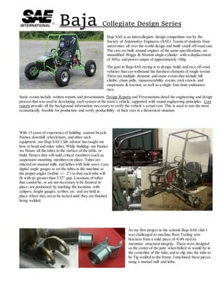
  • 1. Baja Collegiate Design Series Baja SAE is an intercollegiate design competition run by the Society of Automotive Engineers (SAE). Teams of students from universities all over the world design and build small off-road cars. The cars are built around engines of the same specifications, an unmodified Briggs & Stratton single-cylinder with a displacement of 305cc and power output of approximately 10hp. The goal in Baja SAE racing is to design, build and race off-road vehicles that can withstand the harshest elements of rough terrain. There are multiple dynamic and static events that include hill climbs, chain pulls, maneuverability events, rock crawls, and suspension & traction, as well as a single four-hour endurance race. Static events include written reports and presentations. Design Reports and Presentations detail the engineering and design process that was used in developing each system of the team’s vehicle, supported with sound engineering principles. Cost reports provide all the background information necessary to verify the vehicle’s actual cost. This is used to rate the most economically feasible for production and verify producibility of their cars in a theoretical situation. With 15 years of experience of building custom bicycle frames,downhill wheelchairs, and other such equipment, our Baja SAE Club advisor has taught me how to bend and miter tubes. While building our frames we fixture all the tubes to the surface of the table, or build fixtures that will hold critical members (such as suspension mounting members) in place. Tubes are mitered on manual mills and lathes with hole saws. I use digital angle gauges to set the tubes in the machine at the proper angles (within +/- .2˚) so that each tube will fit with no greater than 3/32” gap. Locations of tubes that cannot be, or are not necessary to be fixtured in place, are positioned by marking the locations with calipers, height gauges, scribes, etc. and are held in place where they are to be tacked until they are finished being welded. As my first project in the schools Baja SAE club I was challenged to machine Rear Trailing arm brackets from a solid piece of 4140 steelto maximize structural integrity. These were designed so the center of the joint when bolted in would be in the centerline of the tube, and to slip into the tube to be Tig welded to the frame. I machined these pieces using a manual mill and lathe.
  • 2. An efficient and lightweight means of holding required kill switches on multiple locations of the car with quick and easy way of replacing them if damages is critical. With that I mind I designed a lightweight clamp made of 6061 Aluminum. These ‘sandwich’ style clamps keep the kill switches could be secured to any flat surface with 8-32 bolts. I machined them on a manual mill and ran through a media tumbler to eliminate any stress risers that may cause to aluminum to fracture due to stress and vibration. Due to the cars weighing approximately 350 pounds, and the nature of how minute aspects like weight effects the overall performance of the car, a rack and pinion steering system is used over a fluid power steering system. The rack housing is made of 6061 Aluminum to reduce weight, and brass sleeve inserted bushings to reduce wear. The rack,pinion gear,and rod ends are made of Grade 6 Titanium for strength and wear resistance in the harsh environments. The rod ends, made of titanium, are designed to withstand 2,700lbs of force at a 20˚ angle before bending. Machined pockets in the side of the rod end reduce weight while not compromising strength. The drilled holes act as both weight reduction and location pin holes for the fixture in the 3 axis CNC mill when the part needs to be indexed. The rack and pinion gears were machined on manual horizontal mills. In a previously designed reduction gearbox, linked to the engine with a belt driven CVT, implemented the use of a Limited Slip Differential (LSD). Through testing it was determined the effectiveness was obsolete. A spool was decided to replace the LSD reducing the overall weight of the gearbox by 9.7 pounds. I used a Wire EDM for the cutting of the internal splines, tabs, and the bolt pattern of the spool. I also designed and made the fixture to hold the part while in the EDM machine. Through tuning of the CVT between the 2015 and 2016 competition seasons,a net gain of 11 mph was achieved. It was determined with the current gearbox housing a gear set with a custom pitch could be made with use of the Wire EDM to lower the reduction ratio. By doing this an additional 3 mph was achieved.
  • 3. In some situations where parts weren’t easily available or practical for use in a prototype testing situation, mock parts were made to simulate their placement. This is a mock shock I designed that was used to verify the placement of the shock mounting locations for the desired ride height at full droop, and at full compression. It was also used as a jig for holding the shock tabs in place while they were welded. In order to make this in a timely manner, a manual mill was used. A belt sander to form the radiuses, and a manual lathe was used to make washers so the shoulder bolts that were used could allow the 2 pieces to slide, or be snugged down without causing damage to the surface of the jig. The most critical component that we most commonly see breaking for other teams during the competitions are gear boxes. With the help of G-Force Transmissions to determine the width of the gear teeth and minimum web thickness, a new gearbox was designed to withstand a rating of 40 horse power. This gearbox was designed to use the axel as a suspension member. This requires the casing and internals to withstand all the forces that are seen through a typical 3 point trailing arm suspension. The gear teeth were cut using a Wire EDM. This was in part for the desire to have a small and lightweight unit, and in order to achieve that goal the pitch angles of the gears would not be a standard angle. This also allowed multiple gearing ratio sets to be made so that testing of theoretical gearing ratio, against ratios greater and smaller to determine if the theoretical is the best, or to change the setup for race track conditions. Although our program doesn’t focus on EDM processes as much as manual and CNC mills and lathes, I decided to take on the task of learning and becoming more familiar and comfortable running the Wire EDM machines. Before I was able to cut the 30+ gears for the 5 different ratios in the new gearbox, I made a fixturing plate and clamps. When I cut the first gear internal stresses of the steel caused the material to spring closed on the cut wire path. In order to resolve this problem a metal tab with a drilled start hole for the wire was welded to the outside of the stock in order keep the outer material from springing closed where the wire entered the stock. I also tempered the gear blanks to relieve the atoms in the metal. After the blanks were tempered one side of the blank was ground flat for both the ability to sit flat on the fixture in the EDM machine, and to locate flat against the vice jaws in the lathe when turning the face profile of the gear. Wire EDM machines also allow to maintain high precision and accuracy. The tight tolerances on the gear teeth and splines also help to reduce backlash which reduces the risk or breaking gears due to binding or sudden force. With the featuring methods I developed, a tolerance of +/_.001 of an inch was achieved when measured over rolls. Although this is a wide tolerance for a Wire EDM machine. This was determined to be due to backlash in the machine. When I heat treated them I wrapped them in a paper towel and put them into an oven with Argon gas. The towel was so that when the moisture evaporated the towel would burn, burning all the oxygen left in the furnace, reducing surface oxidation.
  • 4. In order to eliminate even more weight, the edges of the gear teeth were machined off to the compression angle where the mating gear teeth are fully engaged. The center webbing of the gears are machined out to .100 of an inch to remove unneeded material. MasterCAM X9 was used in all of the programing for the Wire EDM machines and the CNC Lathes. Before any critical parts that take numerous hours of machine time or are made of expensive materials were made, they were first 3D printed and test fitted for fit and function to ensure that no modification was needed. For cost and time efficiencies, we chose to use Stratasys FDM over the improved quality of an Objet30 SLA machine due to the cost of build and support material.
  • 5. Engine Machining/Modification Fuel plates are found on 94-98.5 Cummins with the 12-valve engine and the Bosch P7100 pump, also known as a p-pump. Fuel plates are one of the main controls for how much fuel gets into the engine. By changing the original fuel plates to an aftermarket or custom plate allows for faster turbo spooling and more power. I was able to reverse engineer this fuel plate with an optical comparator and make a few minor changes to the ramp angles combining different aspects of two plates, one that allows the engine to be economical and efficient at low speeds, and the other to have a high torque and power output in high RPM situations. I machined these with a Wire EDM to ensure precision and having the ability to have multiple blanks stacked so they can be cut in a single operation. From 1839 when the alloy was first invented, and used in many engines until approximately the mid 1950’s, a “Babbitt” bearing was a poured alloy metal bearing used as a non- galling surface between the cast iron block and the steelcrank shafts. These poured bearings commonly needed replaced after around 40,000 miles. This is a minimum of 1/4th of that of modern steel bearings that are now used in vehicles today. This project was brought to me by the Automotive Restoration department at my college to build a fixture to bore out the main crank shaft bore of this Model A Ford engine in order to fit the new steel bearings. The Camshaft and Crankshaft are gear driven timing rather than today’s chain and belt timing systems. This required an accuracy of -/+.0005 of an inch from the centers of both shafts, and along the length of the engine to make sure the transmission aligns properly. Because the boring bar and fixture are custom made, I had to design and machine a measuring device had to be made to set the length of the cutting bits. The measuring device frame is hinged so that it can be clamped around the boring bar while it is still in the fixture. The bottom of the lower half of the frame is spring loaded to keep constant pressure of the dial indicator tip on the tip of the cutting bit for accurate measurements. To set the length of the cutter bits, there is a screw with a fine threaded bolt on the bottom of the measuring frame that pushes the bit further out of the boring bar. As an elective in college I decided to take an Automotive Machining class. In this class I brought in a Chevrolet 5.7L Engine and was taught how to completely rebuild an engine and calculate compression and volume displacement. During the limited class time during the semester that we had, I had the ability to teardown, clean, bore, sleeve, and hone an engine block. I also had the opportunity to grind valves and valve seats,insert bronze valve sleeves, and how to machine replacement steel valve sleeves and proper post processes.
  • 6. Extras Woodworking is a hobby that I enjoy. I believe a good woodworker has to pay attention to the fine details in everything that they do. This dump truck and bulldozer in these pictures are no exception. From the instrumentation etched into the dash, down to the details as small as the side markers and cab lights and the jack stand on the trailer, I left no detail out. When building boxes or plaques corners and curves can be difficult but have to be done properly to avoid gaps and ensure symmetry. In high school and in college I was part of a competition called RoboBots. RoboBots is very similar to the well-known television show series, Battlebots, where people build Remote Controlled combat ‘Robots’ weighing 15 pounds and designed by students. In 2012 the team and I had placed second at our regional competition, RoboBots, and had gone onto the National Robotics League (NRL) competition in Indianapolis where we placed 3rd in the United States. During my freshman year at the University of Pittsburgh another student from which I had met at the NRL competition and had taken 2nd place decided to start the Physics, Engineering, and Robotics club where we built and designed robots. I personally designed the robot in this picture and had to determine how to place all of the components in the Robot. Later in my Senior year of college after transferring to the Pennsylvania College of Technology I had been asked if I wanted to be part of a the restarting of the S.W.O.R.D. Club (Student Wildcats of Robotic Design), of which I became the president of the club. As a project to challenge myself and learn how to use machinery that I have never used before, I decided to make an AR-15 flash suppressor. First I turned the general shape and bore on a lathe. I then set up an indexing head on a manual mill to drill the holes and machine the “Crown” shape on the end of the suppressor. Then I tipped the head of the mill and machined the holes and slots at a 20˚ angle. Then I used a HSS turning tool blank that a sharpened into a point for treading, but used to add aesthetic markings along the body of the piece.
  • 7. During the summer of 2015 I was a Manufacturing Process Engineer Inter at CPGInternational in the Azek Building Products, Siding division. The Azek Siding division at the time of my internship was just starting to transition into the starting phases of manufacturing. For years previous they had used a small prototype machine to develope the product. My job responsibilities included determining how to package the product and implement Lean manufacturing processes,shipping quantities and methods, maintain quality of the product as well as determining a basline quality, developing process Sequence of Procedures,new employee training and management, and post process machining and process improvement. When determining how to package the product, I needed to determine a method that was both cost effective and efficient. For all the decicions that were made I implemented tests to back up all the decicions that were made. Some of the problems that I encountered were how to carry and place the boxes on a pallet that they would not be damaged easily or be unstable, how to sealthe boxes, limitations on size and weight of a tractor trailor load, weight limitations of a standard forklift in effort to eliminate hasstle when delivered to customers. How the boxes were carried also had a big effect on how the product inside the box reacted. When the parts where carried horizontally in the box the box tended to bow and caused a potential risk for cracking a part of the product that didn’t effect the funtionality of the part, but by carrying the parts vertical the rigidity of the box increased and no damage was caused to the parts. When sealing the boxes three methods were tested,taping, hot melt glues, and banding. The number of bands used down the length of the box was determined by how much the top flap of the box would open when lifted from the ends. Tape and Hot Melt Glues were tested by sealing the box and using a force meter to measure the force needed to break the seal of the box ends. I also determined the price of effectivly sealing the box ends by down to the cost per foot of tape and tape used per box versus the grams of glue needed to seal a box. I also created a working Excel spread sheet that incorperated order quantities of materials and their prices for packaging of a single box and a full pallet, that updated when prices were changed. The Excel spread sheet also broke down quantites of materials into cost per foot of banding and grams of Hot Melt used per box.
  • 8. As part of the packaging the ergonomics for an operator packing parts was critical, so I made a prototype packaging table. Work shifts were planned for ten hours a day, 4 days a week for each work crew,but for producton to run 20 hour a day 7 days a week. It was critical for all the components of packaging area not to interfear with the tasks that needed to be completed and not to cause physical discomfort over time. The packaging location consists of a table where the product is placed after it is machined, an inspection station, packing cradle and slip layer layer stand, banding machine, and roller table. The ergonomic aspects of the packing area first include the inspection platform. The operator pulls a piece of siding on the angled gauge of the table to inspect it. They then take the piece and place it in the box that is located so the operator does not have to bend over. A stop at the end of the cradle that flips up, ensures that when parts are placed in the box they can be pued to the stop so the are all stacked tight to easily close the ends of the box. Between each piece of siding where the faces are together a slip layer is placed between them to keep the surfaces from becoming damaged. The stand with the roll of paper has a rotary cutter that is on drawer slides so that when it is needed it can be pulled closer to the box, and retracted to be out of the way when the box end is being sealed. When searching for a Hot Melt Unit, we decided to order a system with 2 hoses so that the operator would not have to drag it from one end of the table to the other to seal the box. Quality is key for any product. Without a consistent reliable product it is impossible to build and maintain a loyal client base. This lead to the implementation of numerous quality control devices. The aspects that we wanted to inspect were dimensional, color gloss level, color shade, thickness of paint layer on the parts, and monitoring pin holes or bubbles in the paint that indicate a problem in the application process or paint mixture. For all of the inspection processes I created a baseline measurement and an acceptable pass or fail tolerance. Because most of these systems were new to all new hired employees, and employees from other divisions of the company, I had to write detailed SOP’s so that there could be no questions about the sequence of how to operate the equipment properly and determine a passing or failing part quality.
  • 9. The production machine consisted or three robots, two for spraying paint and mold rlease agent, and the third for applying the product material. Each robot is resposible for two parts of a mold. The two paint robots would paint one mold from the left and the right side of the production line simultaniously. After which point, the doors to the spray booth close, the robots move to paint the second set of molds, and the the halves of the painted molds are shuttled to the center bay. At his point the third robots applies a two part expandable foam infused with fiberglass that is sprayed onto the same portion of the mold before the lid lowers into place. This process leaves a small amount of flash on the parts that has to be removed along with the locking system the needs to be machined into the parts. When the machine was installed the company had written a machining program to for the machine; However,the machining process was slower than the time for the parts in the mold to cure. Given my maching backround, and a lack of Computer Aided Machining (CAM) software,I hand wrote another program for the machine. I effectivly shortened the machining time and quality of the parts by almost a full two minutes, from the approximate original five. The CNC machine that I programmed has a 5 foot wide by 33 foot table with dual spindle heads. The table is divided into two parts, one for each side of the production cell. Rather than waiting for both sides to be loaded with parts we decided to implement a push button activation that acted as a selector switch to tell the machine which side of the table to machine. This also involve changing the program again into a 3 parts, a main program with IF statements that used the input from the push buttons, and 2 sub programs. This required me to connect wires into the main panel of the machine, and to be certain no damage was going to be caused to the machine, I had to use a Voltage meter to determine the low voltage power outputs to to be sent to the inputs of the machine when the selector buttons were pushed. Because of the machining process, two tools are required. The first tool is shorter than the other, and allows for the dust hood to fully enclose around the cutter which cleans up all the chips. However,the second tool, because of the complexity of the locking joint, the tool was much longer and prevented the back shield from enclosing to tool to effectively remove all the chips. The first solution I had tried was to extend the back shield and replace the short tool with a longer heat shrunk tool holder; however, this caused a lot of vibration and reduces speed of the machine. I then decided it would be better to design a unit that would sit behind the head and fill the gap, as well as adding an additional vacuum source to remove the chips more efficiently. Picture of the first side of the production cell during installation without spray booth enclosure