Recommended
PPTX
PPTX
PDF
PDF
PDF
PDF
PPTX
PPT
パワーデバイスのデバイスモデリング2007(PPT)
PPTX
PDF
PPTX
PPTX
回路解析シミュレータの活用方法と 最新プロジェクト事例
PDF
PPTX
太陽光シミュレーションセミナー資料(マルツエレック主催2013年12月13日開催)
PDF
Overview and Products of Bee Technologies (05APR2011)
PDF
Overview and Products of Bee Technologies (30JUN2011)
PDF
PDF
Overview and Products of Bee Technologies (29NOV2011)
PDF
PPTX
PDF
PDF
Overview and Products of Bee Technologies (05SEP2011)
PDF
PDF
PDF
PDF
PDF
PSpiceアプリケーションセミナー(06DEC2012)
PDF
モーターのアプリケーション回路シミュレーションのソリューション
PDF
PPTX
More Related Content
PPTX
PPTX
PDF
PDF
PDF
PDF
PPTX
PPT
パワーデバイスのデバイスモデリング2007(PPT)
What's hot
PPTX
PDF
PPTX
PPTX
回路解析シミュレータの活用方法と 最新プロジェクト事例
PDF
PPTX
太陽光シミュレーションセミナー資料(マルツエレック主催2013年12月13日開催)
Similar to ビー・テクノロジーの事業内容(2011) 大阪版
PDF
Overview and Products of Bee Technologies (05APR2011)
PDF
Overview and Products of Bee Technologies (30JUN2011)
PDF
PDF
Overview and Products of Bee Technologies (29NOV2011)
PDF
PPTX
PDF
PDF
Overview and Products of Bee Technologies (05SEP2011)
PDF
PDF
PDF
PDF
PDF
PSpiceアプリケーションセミナー(06DEC2012)
PDF
モーターのアプリケーション回路シミュレーションのソリューション
PDF
PPTX
PDF
2012年1月27日発表原稿(ビー・テクノロジー)
PDF
Overview and Products of Bee Technologies (19JAN2012)
PDF
PPTX
ビー・テクノロジーの事業内容(07NOV2012)
More from Tsuyoshi Horigome
PDF
10-Channel Resistance Measurement Design
PDF
10-channel resistance measurement circuit configuration and mechanism
PDF
Theory and design of ultra-directional parametric speakers
PDF
Electro-Tactile Displays A Trajectory of Stability and Immersion
PDF
皮膚下の神経を電気的に刺激して触覚を提示する電気触覚ディスプレイの仕組みと設計手法の解説
PDF
Marketing and Sales Relationship Diagram
PPTX
SPICEモデルとは? (SPICEモデルの種類と用途別の選定方法についての要約)
PDF
TI TPS544x25 (TPS544B25/C25) - Block Diagram
PPTX
Setting KPI of Estimation Department Division
PPTX
回路ブロック図の事例(PMBus 対応、周波数同期機能搭載、4.5V ~ 18V、20A 同期整流 SWIFT™ 降圧コンバータ)
PPTX
STHV64SW(STマイクロエレクトロニクス)のデータシートの要約について(Suitable for ultrasound imaging applic...
PDF
Safety Lock Circuits (LTspice + Explanation)
PPTX
H8500-based Scintillation Detection System (Block Diagram) by Bee Technologies
PPT
Package Design Design Kit 20100009 PWM IC by Bee Technologies
PDF
Wio LTE JP Version v1.3b- 4G, Cat.1, Espruino Compatible\202001935, PCBA;Wio ...
PDF
High-frequency high-voltage transformer outline drawing
PPTX
高周波回路のノイズ抑制について回路設計、基板設計、基板製造における対策方法について
PPTX
sub-GHz帯域(315MHzや920MHz)で使用する際のポイントについてのご説明
DOCX
Basic Flow Chart Shapes(Reference Memo)for word version
PPTX
Update 40 models( Solar Cell ) in SPICE PARK(JUL2024)
Recently uploaded
PDF
【Overview】EXPERT Growth Hack Report_202602.pdf
PDF
合同会社エンジニアリングマネージメント会社説明資料_2026-02 Engineering Management LLC
PPTX
★【dodaキャンパス】27卒向け【交換できるくん】会社紹介説明資料_vol3★
PDF
260203_fy2025_3q_ broadmedia Corporation.
PDF
インパクト投資家の7つの規律 SIR インパクト投資家が知るべき規律は何か?.pdf
PDF
【会社紹介資料】株式会社カンゲンエージェント [ 2026/02公開 ].pdf
PDF
株式会社イロコト_採用向け_会社紹介資料_2026年度(Webデザイナー・ディレクター・フロントエンドエンジニア向け)
ビー・テクノロジーの事業内容(2011) 大阪版 1. Copyright (C) Bee Technologies Inc. 2011
ビー・テクノロジーの事業内容
株式会社ビー・テクノロジー
http://www.beetech.info/
horigome@bee-tech.com
2011年11月29日(火曜日)
2011
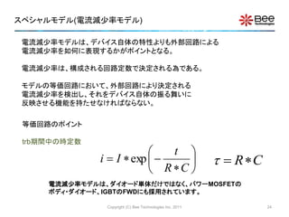
~小信号からパワーエレクトロニクスまで~
~シミュレーションでイノベーションを目指す~
1
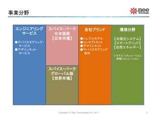
2. 事業分野
Copyright (C) Bee Technologies Inc. 2011
エンジニアリング
サービス
●デバイスモデリング・
サービス
●デザインキット・
サービス
スパイス・パーク
グローバル版
【世界市場】
自社ブランド
●シンプルモデル
●コンセプトキット
●デザインキット
●デバイスモデリング
教材
環境分野
【太陽光システム】
【スマートグリッド】
【自然エネルギー】
システム・シミュレーション
詳細シミュレーション
スパイス・パーク
日本語版
【日本市場】
2
3. お客様を徹底的にサポートする
Copyright (C) Bee Technologies Inc. 2011
[第一の壁]
回路解析
シミュレータの導入
スパイス・パーク
デバイスモデリング
サービス
でサポート
お客様の回路図を
回路解析シミュレー
ションデータ一式で
ご提供
[第二の壁]
自分がシミュレーショ
ンしたい電子部品の
スパイスモデルが揃
わない。
各回路方式のシミュ
レーションのテンプ
レートをご提供
デザインキット
シンプルキット
[第三の壁]
シミュレーションが実
機波形と合わない。
ゼロから動かすのは
物凄く工数がかかる。
フリーソフトの回
路解析シミュレー
タLTspiceを導入
すれば第一の壁
はありません。
LTspiceは、フリーソフトですが、商用の回路解析シミュレータと比較して同等の機能を持っています。
3
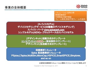
4. 事業の全体概要
Copyright (C) Bee Technologies Inc. 2011
お客様の回路解析シミュレーション環境にてソリューションでご提供します
シミュレーション活用分野
新規回路設計
代替部品の動作検証
クレーム解析(原因不明クレームの追求)
4
5. デバイスモデリングサービス
お客様の必要なスパイスモデルをご提供致します(等価回路技術を駆使してモデル化します)
Copyright (C) Bee Technologies Inc. 2011
[半導体部品] サイリスタ 水晶発振子
ダイオード PWM IC 抵抗
ショットキ・バリア・ダイオード アナログIC [バッテリー]
ツェナー・ダイオード デジタルトランジスタ アルカリ電池
レーザー・ダイオード BRT リチウム電池
LED デジタルIC リチウムイオン電池
Junction FET PUT ニッケルマンガン電池
MOSFET 水晶振動子 ニッケル水素電池
トランジスタ フォトダイオード オキサイド電池
ダーリントン・トランジスタ PINダイオード マンガン電池
IGBT ESDデバイス 太陽電池
ボルテージ・リファレンス バス・スイッチ 鉛蓄電池
ボルテージ・レギュレータ [受動部品] リチウムポリマー電池
シャント・レギュレータ セラミックコンデンサ [機構部品]
オペアンプ 電解コンデンサ トグルスイッチ
コンパレータ フィルムコンデンサ スピーカー
サイダック チョークコイル [モータ]
フォトカプラ コモンモード・チョークコイル DCモータ
光デバイス チョークコイル ステッピングモーター
バリスタ トランス [ランプ]
サージ・アブソーバ コイル 白熱電球
サーミスタ コア ハロゲンランプ
5
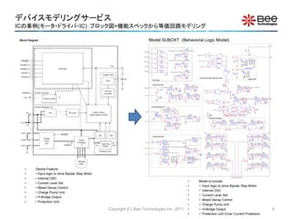
6. デバイスモデリングサービス
ICの事例(モータ・ドライバ・IC):ブロック図+機能スペックから等価回路モデリング
Copyright (C) Bee Technologies Inc. 2011
• Device Feature:
• • Input logic to drive Bipolar Step Motor
• • Internal OSC
• • Current Level Set
• • Mixed Decay Control
• • Charge Pump Unit
• • H-Bridge Output
• • Protection Unit
ERNFA
IF( V(PHASE_A)>0.75, V(IMX_A)-100m, -V(IMX_A))
EVALUE
OUT+
OUT-
IN+
IN-
RRNFA10
RNFAILVA4
CRFA
100p
IC = 0
0
Output Control (Mixed Decay Control)
MDA1
RMDA1
1MEG
0
U19
XOR
1
2
3
PHASE_A
U20
INV
1 2NMDC
OSC
MDA
U17
XOR
1
2
3
MDA
PHASE_A
U18
INV
1 2
Q
B
Q
A
U11
JKFFR
J
1
CLK
2
K
3
R
4
Q
5
Q
6
+
-
+
-
S_UA1
S
VOFF = 2.5V
VON = 10V
U12
JKFFR
J
1
CLK
2
K
3
R
4
Q
5
Q
6
V2
AC =
TRAN =
DC = 5
+
-
+
-
S_LA1
S
VOFF = 2.5V
VON = 10V
0
NMDC3
0
U16
TFFR
CLK
2
R
3
T
1
Q
4
Q
5
RGA1 10k
OA1
NMDC4
OA2
NMDC1
RGA3 10k
EMDA2
IF( V(PHASE_A)>0.75 & V(RST_A)<0.75, 3.5, V(MDA1) )
EVALUE
OUT+
OUT-
IN+
IN-
U13
INV
1 2
MDCA2
NMDC6
0
EGUA1
IF( V(CTRLA1)<0.75 & V(MDA4)<0.75 ,V(Ccp_A),0 )
EVALUE
OUT+
OUT-
IN+
IN-
GU1_A
NMDC2
RMDA2 10
MDA2
0
NMDC5
0
RMDA
1k
EGLA1
IF( V(CTRLA1)<0.75 & V(MDA4)<0.75 ,0,V(Ccp_A) )
EVALUE
OUT+
OUT-
IN+
IN-
CMDA2
100p
IC = 0
GL1_A
0
CTRLA
HI
RSTCA
0
VLA
EMDA3
IF( V(PHASE_A)<0.75 & V(RST_A)<0.75, 0, V(MDA1) )
EVALUE
OUT+
OUT-
IN+
IN-
OUT_A
VM
MDCA3
0
GND
RMDA3 10
MDA3
+
-
+
-
S_UA2
S
VOFF = 2.5V
VON = 10V
CMDA3
100p
IC = 0
+
-
+
-
S_LA2
S
VOFF = 2.5V
VON = 10V
EMDA4
IF( V(PHASE_A)>0.75, V(MDA2), V(MDA3) )
EVALUE
OUT+
OUT-
IN+
IN-
OA3
MDCA4
0
0
OA4
RGA2 10k
RMDA4 10
MDA4
RGA4 10k
CMDA4
100p
IC = 0
EGUA2
IF( V(CTRLA1)>0.75 & V(MDA4)>0.75 ,V(Ccp_A),0 )
EVALUE
OUT+
OUT-
IN+
IN-
GU2_A
0
0
EGLA2
IF( V(CTRLA1)>0.75 & V(MDA4)>0.75 ,0,V(Ccp_A) )
EVALUE
OUT+
OUT-
IN+
IN-
GL2_A
0 GND
OA5
OUT_A1
VM
CR
VOSC
TD = 1.25ns
TF = 10n
PW = {3*tosc/4}
PER = {tosc}
V1 = 0
TR = 10n
V2 = 5
0 0
OSC
R8
1MEG
V1
TD = 0
TF = {tosc/4}
PW = 10n
PER = {tosc}
V1 = 1.9V
TR = {3*tosc/4}
V2 = 3.1V
PARAMETERS:
tosc = {0.523*(Cosc*Rosc+600*Cosc)}
GND
Vchop
TD = 1.25ns
TF = 10n
PW = {5*tosc}
PER = {tosc*8}
V1 = 0.5
TR = 10n
V2 = 5
0
f chop
0
R_chop
1MEG
+
-
+
-
S_UB1
S
VOFF = 2.5V
VON = 10V
+
-
+
-
S_LB1
S
VOFF = 2.5V
VON = 10V
0
RGB110k
OB1
OB2
RGB310k
EGUB1
IF( V(CTRLB1)<0.75 & V(MDB4)<0.75 ,V(Ccp_A),0 )
EVALUE
OUT+
OUT-
IN+
IN-
0
GU1_B
0
EGLB1
IF( V(CTRLB1)<0.75 & V(MDB4)<0.75 ,0,V(Ccp_A) )
EVALUE
OUT+
OUT-
IN+
IN-
GL1_B
ECcp_A1
V(Cp_ON)+V(VM)-2
EVALUE
OUT+
OUT-
IN+
IN-
0
VLB
ENFA
IF( V(PHASE_A)>0.75, V(IMX_A), -V(IMX_A)+100m)
EVALUE
OUT+
OUT-
IN+
IN-
VM
GND
+
-
+
-
S_UB2
S
VOFF = 2.5V
VON = 10V
ECcp_A
IF( V(STANDBY)>0.75, V(Q_Ccp_A), 0)
EVALUE
OUT+
OUT-
IN+
IN-
0
ILVA3
RNFA10
QP2
R6125
NFA
CNFA
100p
IC = 0
+
-
+
-
S_LB2
S
VOFF = 2.5V
VON = 10V
QP3
0
Ccp_A
OB3
0
ERST_A
IF( V(ENABLE_A)<0.75 | V(STANDBY)<0.75 | V(ISDA)>0.75, 0, 5 )
EVALUE
OUT+
OUT-
IN+
IN-
PARAMETERS:
VM = 24V
0
OB4
QP1
RGB210k
Chopper OSC
Rcp_on
100
ILVA1
RGB410k
RRST_A10
Cp_ON
RST_A
Ccp_on
0.22uF
IC = 0
EGUB2
IF( V(CTRLB1)>0.75 & V(MDB4)>0.75 ,V(Ccp_A),0 )
EVALUE
OUT+
OUT-
IN+
IN-
ECcp_B
IF( V(STANDBY)>0.75 ,V(VM)-2+V(VCcp_C)/2.5 ,V(VM)-0.7)
EVALUE
OUT+
OUT-
IN+
IN-
CRST_A
100p
IC = 0
G_RsA
I(VLA)
GVALUE
OUT+
OUT-
IN+
IN-
0
0
GU2_B
0
ECcp_C
IF( V(STANDBY)>0.75 ,V(VCcp_C), V(VM)-0.7 )
EVALUE
OUT+
OUT-
IN+
IN-
EGLB2
IF( V(CTRLB1)>0.75 & V(MDB4)>0.75 ,0,V(Ccp_A) )
EVALUE
OUT+
OUT-
IN+
IN-
RS_A
GND 0
GL2_B
QP4
RCcp_C 50
E_VL1_A
I(VLA)
EVALUE
OUT+
OUT-
IN+
IN-
0
0
0
IFBA1 ILA
R_VLA10
V_Q4
GND
OB5
R5
100k
VM
0
C_VLA
100p
VDD
RDD1
2.5k
EChrg
IF(I(V_Q4)>10m, 3.5, 0)
EVALUE
OUT+
OUT-
IN+
IN-
E_EA_A
LIMIT(1E5*V(ILA,TRGA),5,0)
EVALUE
OUT+
OUT-
IN+
IN-
GND
Q_Ccp_A
0
CTRLAIFBA4
PARAMETERS:
CP_PW = {800*Ccp2}
CP_PER = {18.5u+1800*Ccp2}
CP_V2 = {250E6*Ccp2}
Protection Unit (ISD)
0
CTRLA1
REAA10
Ecp_on
IF(V(STANDBY)>0.75, 6.5, 0)
EVALUE
OUT+
OUT-
IN+
IN-
E_ABILA
IF(I(VLA)>0,I(VLA),-I(VLA))
EVALUE
OUT+
OUT-
IN+
IN-
CEAA
100p
IC = 0
0
ISDA1
R_ABILA 10
ETRGA
IF(V(CTRLA1)>1,V(RNFA1),V(NFA1))
EVALUE
OUT+
OUT-
IN+
IN-
Ccp_C
Ccp_B
OUT_B
VcpTD = 0
TF = 10N
PW = {CP_PW}
PER = {CP_PER}
V1 = {VM-1.4}
TR = 10N
V2 = {CP_V2}
0
IFBA3
RTRGA10
C_ABILA
100p
VCcp_C
TRGA
E_ISDA
IF( V(AB_ILA)>V(ISDA_REF) , 5, 0)
EVALUE
OUT+
OUT-
IN+
IN-
0
RV_C
100k
CTRGA
100p
IC = 0
00
ISDA3 ISDA
ERS_A
((V(VM)-V(RS_A))/V(ILA))
EVALUE
OUT+
OUT-
IN+
IN-
RISDA 10
IFBA2
CISDA
100p
IC = 0
0
RRS_A10
EISDA_REF
IF(V(ISDA)<1 | V(STANDBY)<0.75,1.8,-0.1)
EVALUE
OUT+
OUT-
IN+
IN-
RS_A1
CRS_A
100P
ISDA2
0
RISDA_REF10
VM
Current Feedback ( A )
ISDA_REF
CISDA_REF
100p
IC = 0
0
AB_ILA
OUT_B1
CTRLA
PHASE_A
f chop
U27
AND2
1
2
3
U28
AND2
1
2
3
U29
AND2
1
2
3
U30
OR3
1
24
3
CEAA1
30p
IC = 0
U31
INV
1 2
0
R10
100
U32
INV
12
Charge Pump Unit
Input Logic
PHASE_A
ENABLE_A
PHASE_B
ENABLE_B
RPD_EA
RPD_EB
RPD_PA
RPD_PB
GND
RPU_EA
VM
VM
RPU_EB
VM
RPU_PA
RPU_PB
VM
RPD_STB
VM
RPU_STB
STANDBY
R_PIN1
1MEG
GND
TORQUE
0
ETQ
IF( V(TORQUE)>0.75, 1, 0.71)
EVALUE
OUT+
OUT-
IN+
IN-
RTQ
100
CTQ
100P
TQILVA7
R_REFA
1MEG
Vref _A
GND
EIMX_A
0.2*V(Vref _A)*V(TQ)/V(RS_A1)
EVALUE
OUT+
OUT-
IN+
IN-
0
ILVA2
RIMX_A10
IMX_A
CIMX_A
100P
Current Level Set ENFA1
IF( V(RST_A)<0.75 , 0, V(NFA) )
EVALUE
OUT+
OUT-
IN+
IN-
0
ILVA5
RNFA110
NFA1
CNFA1
100p
IC = 0
ERNFA1
IF( V(RST_A)<0.75, 0, V(RNFA) )
EVALUE
OUT+
OUT-
IN+
IN-
RRNFA110
RNFA1ILVA6
CRFA1
100p
IC = 0
0
Model SUBCKT (Behavioral Logic Model)
• Model is include:
• Input logic to drive Bipolar Step Motor
• Internal OSC
• Current Level Set
• Mixed Decay Control
• Charge Pump Unit
• H-Bridge Output
• Protection Unit (Over Current Protection
6
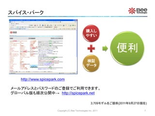
7. スパイス・パーク
Copyright (C) Bee Technologies Inc. 2011
購入し
やすい
検証
データ
便利
3,709モデルをご提供(2011年9月27日現在)
http://www.spicepark.com
メールアドレスとパスワードのご登録でご利用できます。
グローバル版も順次公開中→ http://spicepark.net
7
8. [NEW] シンプルモデル
Copyright (C) Bee Technologies Inc. 2011
ユーザーが定義できるパラメータモデル。あったら便利なアプリ的なスパイスモデル
であり、汎用性があります。詳細は、http://ow.ly/5sw4N をご参照下さい。
製品 価格(円) PSpice版 LTspice版
DCDCコンバータ 15,750 ご提供開始 ご提供開始
DCACインバータ 15,750 ご提供開始 ご提供開始
三相インバータ 15,750 ご提供開始 ご提供開始
DC電源 15,750 ご提供開始 ご提供開始
ヒューズモデル 15,750 ご提供開始 ご提供開始
リチウムイオン電池モデル 84,000 ご提供開始 ご提供開始
ニッケル水素電池モデル 84,000 ご提供開始 ご提供開始
鉛蓄電池モデル 84,000 開発中 開発中
8
9. [NEW] シンプルモデル:DC電源モデル
Copyright (C) Bee Technologies Inc. 2011
I(OUT)
0A 20A 40A 60A 80A 100A 120A 140A 160A 180A 200A
V(OUT)
0V
20V
40V
60V
80V
100V
(160.000,9.990)
(20.000,79.991)
(160.000,9.990)
Rated output voltage
Maximum output current
Rated output line
Rated operation
range
U1
DC_POWER_SUPPLY
VOUT = 80Vdc
IMAX = 160Adc
VMAX = 80Vdc
POWER = 1600W
Operation Area Characteristics
9
10. [NEW] シンプルモデル:ヒューズモデル
Copyright (C) Bee Technologies Inc. 2011
0.001
0.01
0.1
1
10
0.1 1 10 100
FusingTime(Sec.)
Fusing Current (A)
Fig. Shows the complete setting of fuse model parameters by using data from the
datasheet of CCF1N0.4 provided by KOA Speer Electronics, Inc.
Part No.
Current
Rating
(mA)
Internal
R. max.
(m)
I2t (A2,
seconds
)
CCF1N0.4 400 650 0.024
the minimum fusing current
is 620mA, FF = 20m/400m
= 1.55
U1
FUSE
FF = 1.55
I2T = 0.024
IRATE = 400m
RINT = 650m
10
11. [NEW] シンプルモデル:ヒューズモデル
Copyright (C) Bee Technologies Inc. 2011
• The simulation result shows the fusing times, tF, (the time that fuse blows) at
the different fuse currents, IF .
Time
1.0ms 10ms 100ms 1.0s
I(sense)
100mA
1.0A
10A
(24.013m,1.0000)
(960.962u,5.0000)
(6.0051m,2.0000)
tF = 960.962usec. at IF = 5A
tF = 6.0051msec. at IF = 2A
tF = 24.013msec. at IF = 1A
0
RL
1
0
sense
I1
I1 = 0
I2 = {dc_current}
T1 = 0
T2 = 100n
U1
FUSE
FF = 1.55
I2T = 0.024
IRATE = 400m
RINT = 650m
PARAMETERS:
dc_current = 1
Simulation Circuit
*Analysis directives:
.TRAN 0 1s 500u 100u
.STEP PARAM dc_current LIST 1, 2, 5
Simulation Result
0.001
0.01
0.1
1
10
0.1 1 10 100
FusingTime(Sec.)
Fusing Current
Measurement
Simulation
11
12. [NEW] シンプルモデル:ヒューズモデル
Copyright (C) Bee Technologies Inc. 2011
0
RL1
1
0
sense1
U1
FUSE
FF = 1.55
I2T = 0.024
IRATE = 400m
RINT = 650m
I1
IOFF = 0
FREQ = 50
IAMPL = 1
PHASE = -90
0
RL2
1
0
sense2
U2
FUSE
FF = 1.55
I2T = 0.024
IRATE = 400m
RINT = 650m
I2
TD = 0
TF = 10m
PW = 0
PER = 20m
I1 = -1
I2 = 1
TR = 10m
Time
0s 20ms 40ms 60ms 80ms 100ms 140ms 180ms
I(sense1) I(sense2)
-2.0A
-1.5A
-1.0A
-0.5A
0A
0.5A
1.0A
1.5A
2.0A
(149.796m,959.222m)
(59.503m,-987.814m)
• The simulation result shows the fusing times, tF, (the time that fuse blows)
for the same peak current but different in current patterns(waveforms).
tF = 59.503msec. for sine wave
tF = 149.796msec. for triangle wave
Simulation CircuitSimulation Result
.TRAN 0 0.2s 0 100u
Fusing Time vs. Current Pattern
12
13. [NEW] シンプルモデル:リチウムイオン電池モデル
Copyright (C) Bee Technologies Inc. 2011
C is the amp-hour battery capacity [Ah]
– e.g. C = 0.3, 1.4, or 2.8 [Ah]
NS is the number of cells in series
– e.g. NS=1 for 1 cell battery, NS=2 for 2 cells
battery (battery voltage is double from 1 cell)
SOC is the initial state of charge in percent
– e.g. SOC=0 for a empty battery (0%), SOC=1 for
a full charged battery (100%)
TSCALE turns TSCALE seconds into a second
– e.g. TSCALE=60 turns 60s or 1min into a second,
TSCALE=3600 turns 3600s or 1h into a second,
• From the Li-Ion Battery specification, the model is characterized by setting parameters
C, NS, SOC and TSCALE.
Model Parameters:
+ -
U1
LI-ION_BATTERY
SOC = 1
NS = 1
TSCALE = 1
C = 1.4
(Default values)
13
14. [NEW] シンプルモデル:リチウムイオン電池モデル
Copyright (C) Bee Technologies Inc. 2011
• The battery information refer to a battery part number LIR18500 of EEMB BATTERY.
+ -
U1
LI-ION_BATTERY
SOC = 1
NS = 1
TSCALE = 60
C = 1.4
Battery capacity
is input as a
model parameter
Nominal Voltage 3.7V
Nominal
Capacity
Typical 1400mAh (0.2C discharge)
Charging Voltage 4.20V±0.05V
Charging Std. Current 700mA
Max Current
Charge 1400mA
Discharge 2800mA
Discharge cut-off voltage 2.75V
14
15. [NEW] シンプルモデル:リチウムイオン電池モデル
Copyright (C) Bee Technologies Inc. 2011
Time
0s 50s 100s 150s 200s
1 V(HI) 2 I(IBATT)
3.0V
3.2V
3.4V
3.6V
3.8V
4.0V
4.2V
4.4V
1
0A
0.4A
0.6A
0.8A
1.0A
1.2A
1.4A
2
SEL>>SEL>>
V(X_U1.SOC)
0V
0.2V
0.4V
0.6V
0.8V
1.0V
+ -
U1
LI-ION_BATTERY
SOC = 0
NS = 1
TSCALE = 60
C = 1.4
• Charging Voltage: 4.20V±0.05V
• Charging Current: 700mA (0.5 Charge)
Current=700mA
Voltage=4.20V
Capacity=100%
(minute)
Measurement Simulation
SOC=0 means
battery start from 0%
of capacity (empty)
Charge Time Characteristic
15
16. [NEW] シンプルモデル:リチウムイオン電池モデル
Copyright (C) Bee Technologies Inc. 2011
Time
0s 100s 200s 300s 400s
V(HI)
2.6V
2.8V
3.0V
3.2V
3.4V
3.6V
3.8V
4.0V
4.2V
4.4V
0
+ -
U1
LI-ION_BATTERY
SOC = 1
NS = 1
TSCALE = 60
C = 1.4
HI
0
0
IN-
OUT+
OUT-
IN+
G1
limit(V(%IN+, %IN-)/0.1m, 0, rate*CAh )
PARAMETERS:
rate = 1
CAh = 1.4
C1
10n
sense
*Analysis directives:
.TRAN 0 300 0 0.5
.STEP PARAM rate LIST 0.2,0.5,1
.PROBE V(*) I(*) W(*) D(*) NOISE(*)
0.2C
0.5C
1C
(minute)
TSCALE turns 1 minute in seconds,
battery starts from 100% of capacity (fully charged)
• Battery voltage vs. time are simulated at 0.2C, 0.5C, and 1C discharge rates.
Discharge Time Characteristic
16
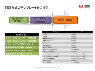
17. 18. 19. 20. 21. 回路方式のテンプレートをご提供
Copyright (C) Bee Technologies Inc. 2011
コンセプトキット
ユニポーラステッピングモータ制御回路
バイポーラステッピングモータ制御回路
アベレージモデルの降圧コンバータ
過渡解析モデルの降圧コンバータ
アベレージモデルの昇圧コンバータ
過渡解析モデルの昇圧コンバータ
デザインキット 分野
FCC回路 電源回路
RCC回路 電源回路
低損失リニアレギュレータ 電源回路
高精度リニアレギュレータ 電源回路
D級アンプ アンプ回路
擬似共振電源回路 電源回路
マイクロコントローラ 電源回路
ステッピングモータドライブ回路 モーター制御回路
PWM ICによる電源回路 電源回路
バッテリー回路(リチウムイオン電池) バッテリーアプリケーション回路
バッテリー回路(ニッケル水素電池) バッテリーアプリケーション回路
バッテリー回路(鉛蓄電池) バッテリーアプリケーション回路
DCDCコンバータ 電源回路
DCモータ制御回路 モーター制御回路
21
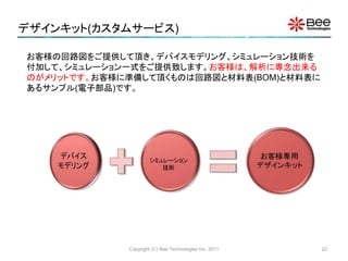
22. デザインキット(カスタムサービス)
Copyright (C) Bee Technologies Inc. 2011
お客様の回路図をご提供して頂き、デバイスモデリング、シミュレーション技術を
付加して、シミュレーション一式をご提供致します。お客様は、解析に専念出来る
のがメリットです。お客様に準備して頂くものは回路図と材料表(BOM)と材料表に
あるサンプル(電子部品)です。
22
23. 24. 25. 26. 27. 28. Bee Technologies Group
お問合わせ先)
info@bee-tech.com
【本社】
株式会社ビー・テクノロジー
〒105-0012 東京都港区芝大門二丁目2番7号 7セントラルビル4階
代表電話: 03-5401-3851
設立日:2002年9月10日
資本金:8,830万円
【子会社】
Bee Technologies Corporation (アメリカ)
Siam Bee Technologies Co.,Ltd. (タイランド)
本ドキュメントは予告なき変更をする場合がございます。
ご了承下さい。また、本文中に登場する製品及びサービス
の名称は全て関係各社または個人の各国における商標
または登録商標です。本原稿に関するお問い合わせは、
当社にご連絡下さい。
Copyright (C) Bee Technologies Inc. 2011 28


![お客様を徹底的にサポートする
Copyright (C) Bee Technologies Inc. 2011
[第一の壁]
回路解析
シミュレータの導入
スパイス・パーク
デバイスモデリング
サービス
でサポート
お客様の回路図を
回路解析シミュレー
ションデータ一式で
ご提供
[第二の壁]
自分がシミュレーショ
ンしたい電子部品の
スパイスモデルが揃
わない。
各回路方式のシミュ
レーションのテンプ
レートをご提供
デザインキット
シンプルキット
[第三の壁]
シミュレーションが実
機波形と合わない。
ゼロから動かすのは
物凄く工数がかかる。
フリーソフトの回
路解析シミュレー
タLTspiceを導入
すれば第一の壁
はありません。
LTspiceは、フリーソフトですが、商用の回路解析シミュレータと比較して同等の機能を持っています。
3](https://image.slidesharecdn.com/26oct2011ltspiceosaka-200813010247/85/2011-3-320.jpg)
![デバイスモデリングサービス
お客様の必要なスパイスモデルをご提供致します(等価回路技術を駆使してモデル化します)
Copyright (C) Bee Technologies Inc. 2011
[半導体部品] サイリスタ 水晶発振子
ダイオード PWM IC 抵抗
ショットキ・バリア・ダイオード アナログIC [バッテリー]
ツェナー・ダイオード デジタルトランジスタ アルカリ電池
レーザー・ダイオード BRT リチウム電池
LED デジタルIC リチウムイオン電池
Junction FET PUT ニッケルマンガン電池
MOSFET 水晶振動子 ニッケル水素電池
トランジスタ フォトダイオード オキサイド電池
ダーリントン・トランジスタ PINダイオード マンガン電池
IGBT ESDデバイス 太陽電池
ボルテージ・リファレンス バス・スイッチ 鉛蓄電池
ボルテージ・レギュレータ [受動部品] リチウムポリマー電池
シャント・レギュレータ セラミックコンデンサ [機構部品]
オペアンプ 電解コンデンサ トグルスイッチ
コンパレータ フィルムコンデンサ スピーカー
サイダック チョークコイル [モータ]
フォトカプラ コモンモード・チョークコイル DCモータ
光デバイス チョークコイル ステッピングモーター
バリスタ トランス [ランプ]
サージ・アブソーバ コイル 白熱電球
サーミスタ コア ハロゲンランプ
5](https://image.slidesharecdn.com/26oct2011ltspiceosaka-200813010247/85/2011-5-320.jpg)
![[NEW] シンプルモデル
Copyright (C) Bee Technologies Inc. 2011
ユーザーが定義できるパラメータモデル。あったら便利なアプリ的なスパイスモデル
であり、汎用性があります。詳細は、http://ow.ly/5sw4N をご参照下さい。
製品 価格(円) PSpice版 LTspice版
DCDCコンバータ 15,750 ご提供開始 ご提供開始
DCACインバータ 15,750 ご提供開始 ご提供開始
三相インバータ 15,750 ご提供開始 ご提供開始
DC電源 15,750 ご提供開始 ご提供開始
ヒューズモデル 15,750 ご提供開始 ご提供開始
リチウムイオン電池モデル 84,000 ご提供開始 ご提供開始
ニッケル水素電池モデル 84,000 ご提供開始 ご提供開始
鉛蓄電池モデル 84,000 開発中 開発中
8](https://image.slidesharecdn.com/26oct2011ltspiceosaka-200813010247/85/2011-8-320.jpg)
![[NEW] シンプルモデル:DC電源モデル
Copyright (C) Bee Technologies Inc. 2011
I(OUT)
0A 20A 40A 60A 80A 100A 120A 140A 160A 180A 200A
V(OUT)
0V
20V
40V
60V
80V
100V
(160.000,9.990)
(20.000,79.991)
(160.000,9.990)
Rated output voltage
Maximum output current
Rated output line
Rated operation
range
U1
DC_POWER_SUPPLY
VOUT = 80Vdc
IMAX = 160Adc
VMAX = 80Vdc
POWER = 1600W
Operation Area Characteristics
9](https://image.slidesharecdn.com/26oct2011ltspiceosaka-200813010247/85/2011-9-320.jpg)
![[NEW] シンプルモデル:ヒューズモデル
Copyright (C) Bee Technologies Inc. 2011
0.001
0.01
0.1
1
10
0.1 1 10 100
FusingTime(Sec.)
Fusing Current (A)
Fig. Shows the complete setting of fuse model parameters by using data from the
datasheet of CCF1N0.4 provided by KOA Speer Electronics, Inc.
Part No.
Current
Rating
(mA)
Internal
R. max.
(m)
I2t (A2,
seconds
)
CCF1N0.4 400 650 0.024
the minimum fusing current
is 620mA, FF = 20m/400m
= 1.55
U1
FUSE
FF = 1.55
I2T = 0.024
IRATE = 400m
RINT = 650m
10](https://image.slidesharecdn.com/26oct2011ltspiceosaka-200813010247/85/2011-10-320.jpg)
![[NEW] シンプルモデル:ヒューズモデル
Copyright (C) Bee Technologies Inc. 2011
• The simulation result shows the fusing times, tF, (the time that fuse blows) at
the different fuse currents, IF .
Time
1.0ms 10ms 100ms 1.0s
I(sense)
100mA
1.0A
10A
(24.013m,1.0000)
(960.962u,5.0000)
(6.0051m,2.0000)
tF = 960.962usec. at IF = 5A
tF = 6.0051msec. at IF = 2A
tF = 24.013msec. at IF = 1A
0
RL
1
0
sense
I1
I1 = 0
I2 = {dc_current}
T1 = 0
T2 = 100n
U1
FUSE
FF = 1.55
I2T = 0.024
IRATE = 400m
RINT = 650m
PARAMETERS:
dc_current = 1
Simulation Circuit
*Analysis directives:
.TRAN 0 1s 500u 100u
.STEP PARAM dc_current LIST 1, 2, 5
Simulation Result
0.001
0.01
0.1
1
10
0.1 1 10 100
FusingTime(Sec.)
Fusing Current
Measurement
Simulation
11](https://image.slidesharecdn.com/26oct2011ltspiceosaka-200813010247/85/2011-11-320.jpg)
![[NEW] シンプルモデル:ヒューズモデル
Copyright (C) Bee Technologies Inc. 2011
0
RL1
1
0
sense1
U1
FUSE
FF = 1.55
I2T = 0.024
IRATE = 400m
RINT = 650m
I1
IOFF = 0
FREQ = 50
IAMPL = 1
PHASE = -90
0
RL2
1
0
sense2
U2
FUSE
FF = 1.55
I2T = 0.024
IRATE = 400m
RINT = 650m
I2
TD = 0
TF = 10m
PW = 0
PER = 20m
I1 = -1
I2 = 1
TR = 10m
Time
0s 20ms 40ms 60ms 80ms 100ms 140ms 180ms
I(sense1) I(sense2)
-2.0A
-1.5A
-1.0A
-0.5A
0A
0.5A
1.0A
1.5A
2.0A
(149.796m,959.222m)
(59.503m,-987.814m)
• The simulation result shows the fusing times, tF, (the time that fuse blows)
for the same peak current but different in current patterns(waveforms).
tF = 59.503msec. for sine wave
tF = 149.796msec. for triangle wave
Simulation CircuitSimulation Result
.TRAN 0 0.2s 0 100u
Fusing Time vs. Current Pattern
12](https://image.slidesharecdn.com/26oct2011ltspiceosaka-200813010247/85/2011-12-320.jpg)
![[NEW] シンプルモデル:リチウムイオン電池モデル
Copyright (C) Bee Technologies Inc. 2011
C is the amp-hour battery capacity [Ah]
– e.g. C = 0.3, 1.4, or 2.8 [Ah]
NS is the number of cells in series
– e.g. NS=1 for 1 cell battery, NS=2 for 2 cells
battery (battery voltage is double from 1 cell)
SOC is the initial state of charge in percent
– e.g. SOC=0 for a empty battery (0%), SOC=1 for
a full charged battery (100%)
TSCALE turns TSCALE seconds into a second
– e.g. TSCALE=60 turns 60s or 1min into a second,
TSCALE=3600 turns 3600s or 1h into a second,
• From the Li-Ion Battery specification, the model is characterized by setting parameters
C, NS, SOC and TSCALE.
Model Parameters:
+ -
U1
LI-ION_BATTERY
SOC = 1
NS = 1
TSCALE = 1
C = 1.4
(Default values)
13](https://image.slidesharecdn.com/26oct2011ltspiceosaka-200813010247/85/2011-13-320.jpg)
![[NEW] シンプルモデル:リチウムイオン電池モデル
Copyright (C) Bee Technologies Inc. 2011
• The battery information refer to a battery part number LIR18500 of EEMB BATTERY.
+ -
U1
LI-ION_BATTERY
SOC = 1
NS = 1
TSCALE = 60
C = 1.4
Battery capacity
is input as a
model parameter
Nominal Voltage 3.7V
Nominal
Capacity
Typical 1400mAh (0.2C discharge)
Charging Voltage 4.20V±0.05V
Charging Std. Current 700mA
Max Current
Charge 1400mA
Discharge 2800mA
Discharge cut-off voltage 2.75V
14](https://image.slidesharecdn.com/26oct2011ltspiceosaka-200813010247/85/2011-14-320.jpg)
![[NEW] シンプルモデル:リチウムイオン電池モデル
Copyright (C) Bee Technologies Inc. 2011
Time
0s 50s 100s 150s 200s
1 V(HI) 2 I(IBATT)
3.0V
3.2V
3.4V
3.6V
3.8V
4.0V
4.2V
4.4V
1
0A
0.4A
0.6A
0.8A
1.0A
1.2A
1.4A
2
SEL>>SEL>>
V(X_U1.SOC)
0V
0.2V
0.4V
0.6V
0.8V
1.0V
+ -
U1
LI-ION_BATTERY
SOC = 0
NS = 1
TSCALE = 60
C = 1.4
• Charging Voltage: 4.20V±0.05V
• Charging Current: 700mA (0.5 Charge)
Current=700mA
Voltage=4.20V
Capacity=100%
(minute)
Measurement Simulation
SOC=0 means
battery start from 0%
of capacity (empty)
Charge Time Characteristic
15](https://image.slidesharecdn.com/26oct2011ltspiceosaka-200813010247/85/2011-15-320.jpg)
![[NEW] シンプルモデル:リチウムイオン電池モデル
Copyright (C) Bee Technologies Inc. 2011
Time
0s 100s 200s 300s 400s
V(HI)
2.6V
2.8V
3.0V
3.2V
3.4V
3.6V
3.8V
4.0V
4.2V
4.4V
0
+ -
U1
LI-ION_BATTERY
SOC = 1
NS = 1
TSCALE = 60
C = 1.4
HI
0
0
IN-
OUT+
OUT-
IN+
G1
limit(V(%IN+, %IN-)/0.1m, 0, rate*CAh )
PARAMETERS:
rate = 1
CAh = 1.4
C1
10n
sense
*Analysis directives:
.TRAN 0 300 0 0.5
.STEP PARAM rate LIST 0.2,0.5,1
.PROBE V(*) I(*) W(*) D(*) NOISE(*)
0.2C
0.5C
1C
(minute)
TSCALE turns 1 minute in seconds,
battery starts from 100% of capacity (fully charged)
• Battery voltage vs. time are simulated at 0.2C, 0.5C, and 1C discharge rates.
Discharge Time Characteristic
16](https://image.slidesharecdn.com/26oct2011ltspiceosaka-200813010247/85/2011-16-320.jpg)
![Copyright (C) Bee Technologies Inc. 2011 17
[事例]LTC4077+Li-Ion Simple Model](https://image.slidesharecdn.com/26oct2011ltspiceosaka-200813010247/85/2011-17-320.jpg)
![Copyright (C) Bee Technologies Inc. 2011 18
[事例]LTC4077+Li-Ion Simple Model](https://image.slidesharecdn.com/26oct2011ltspiceosaka-200813010247/85/2011-18-320.jpg)
![Copyright (C) Bee Technologies Inc. 2011 19
[事例]LTC4077+Li-Ion Simple Model](https://image.slidesharecdn.com/26oct2011ltspiceosaka-200813010247/85/2011-19-320.jpg)
![Copyright (C) Bee Technologies Inc. 2011 20
[事例]LTC4077+Li-Ion Simple Model](https://image.slidesharecdn.com/26oct2011ltspiceosaka-200813010247/85/2011-20-320.jpg)


![【会社紹介資料】株式会社カンゲンエージェント [ 2026/02公開 ].pdf](https://cdn.slidesharecdn.com/ss_thumbnails/hp-260202024348-cf56e236-thumbnail.jpg?width=640&height=640&fit=bounds)
