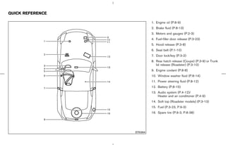
Download to read offline
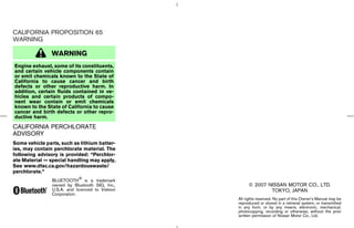
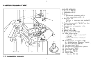
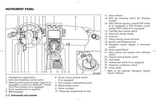
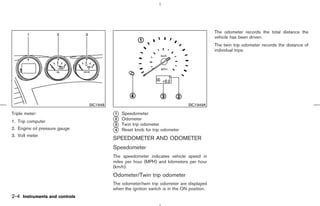
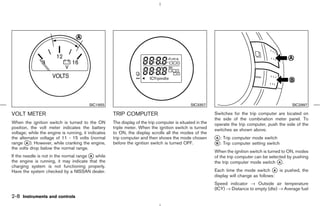
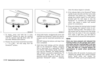

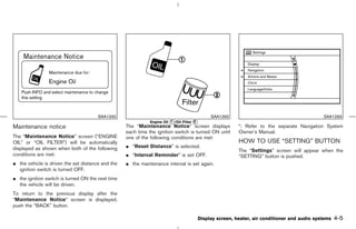
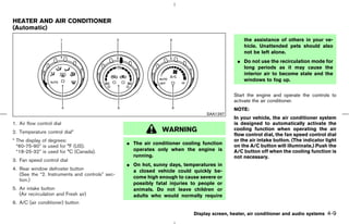
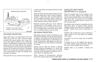
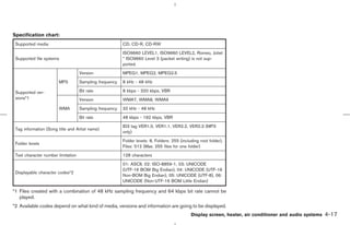
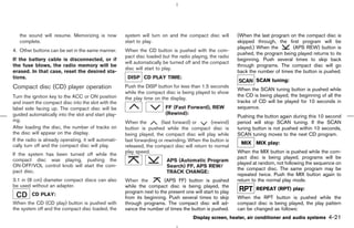
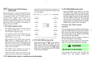
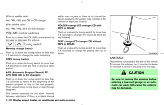
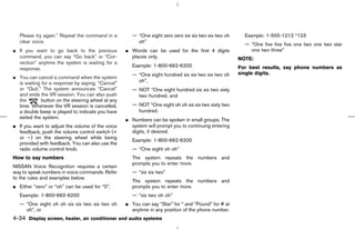
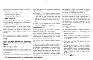
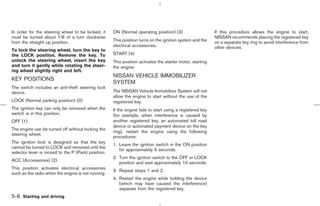
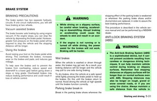
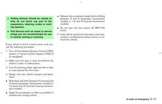
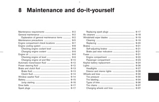
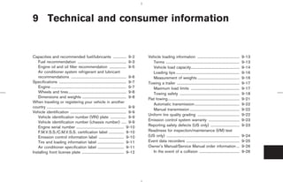
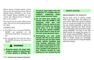
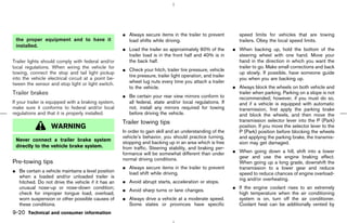
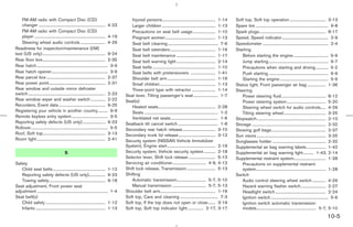
![¼ CD ERR F * — Eject the disc, and check
whether it is a proper audio
CD. (* shows a different
number according to the au-
The display shows the following symbol; (no dio condition.)
mark): 1 CD RPT (Repeat)
CD IN indicator:
1: 1 TR (Track) RPT
CD IN indicator appears on the display when the
CD EJECT: CD is loaded.
When the CD EJECT button is pushed with the
compact disc loaded, the compact disc will be
ejected.
When this button is pushed while the compact
disc is being played, the compact disc will come
out and the system will turn off.
If the compact disc comes out and is not
removed, it will be pulled back into the slot
to protect it. (except for 3.1 in [8 cm] diam-
eter compact discs)
If the following message appears on the display,
push the EJECT button:
¼ CHECK DISC — Eject the disc, and check
whether it is damaged or
inserted upside-down.
4-22 Display screen, heater, air conditioner and audio systems
੬ 07.7.25/Z33-D/V5.0 ੭](https://image.slidesharecdn.com/2008-350-z-120818113132-phpapp01/85/2008-350-z-OWNER-S-MANUAL-162-320.jpg)
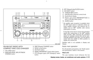
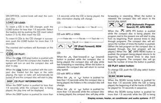
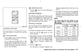
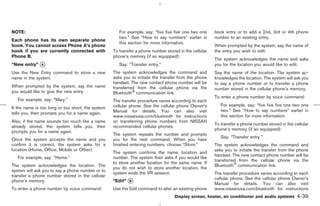
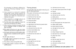
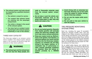
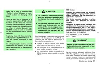
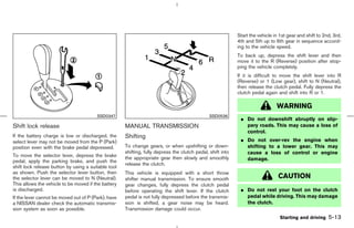
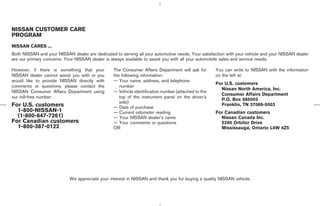
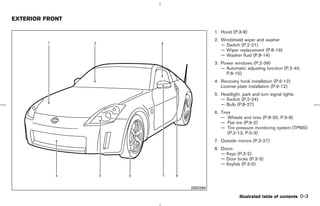
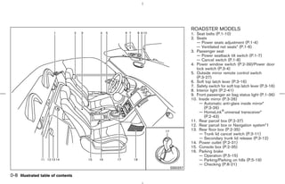
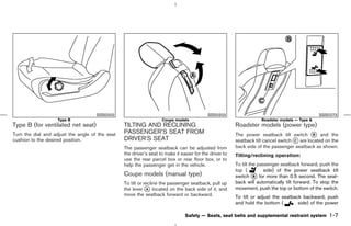
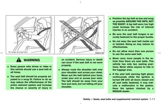
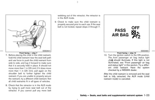
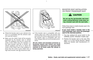
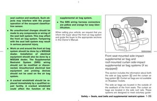
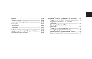
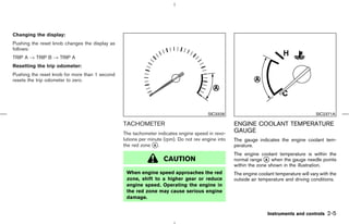
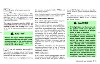
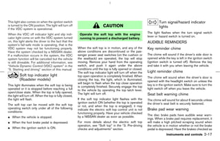
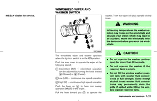
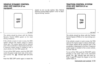
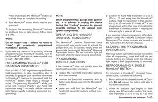
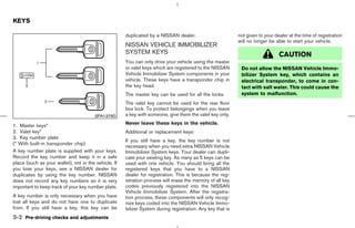
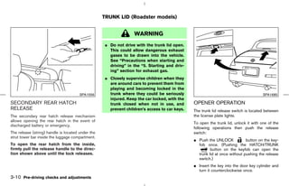
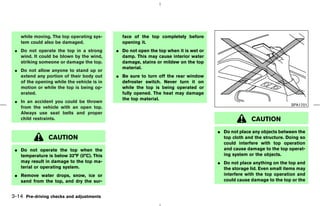
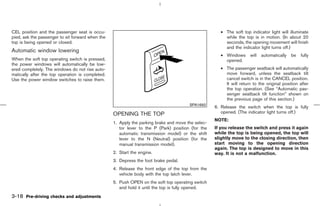
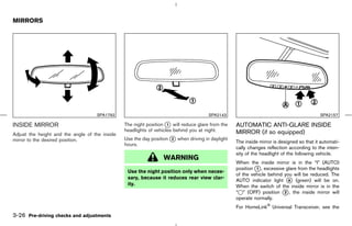
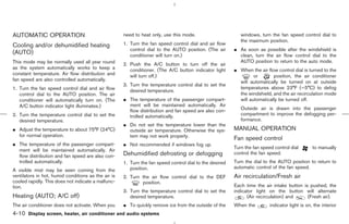
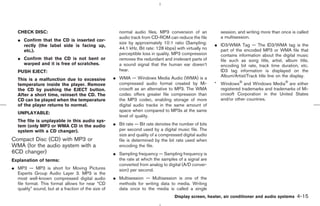
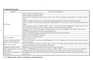
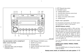
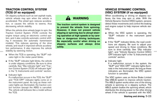
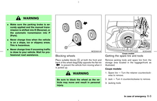
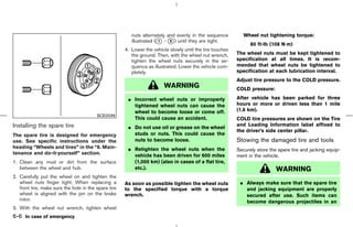
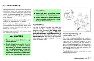
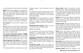
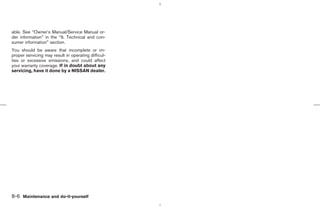
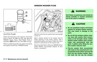
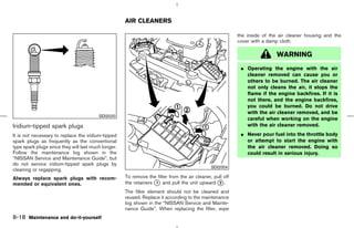
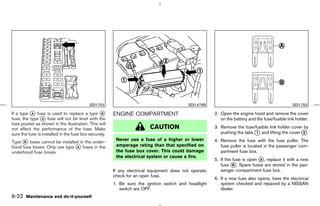
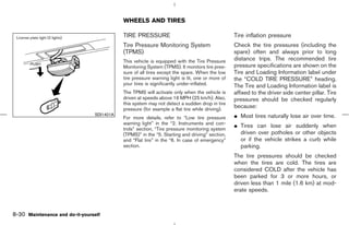
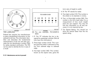
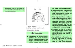
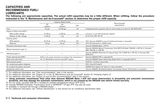
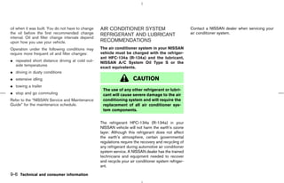
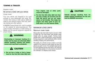
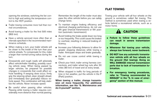
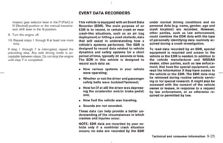
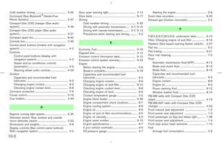
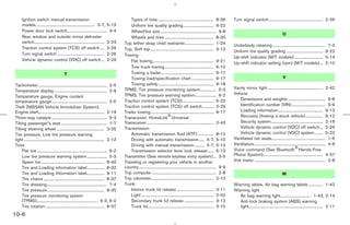
![PARKING BRAKE
Suggested up-shift speeds Suggested maximum speed in each
Shown below are suggested vehicle speeds for gear
shifting into a higher gear. These suggestions Downshift to a lower gear if the engine is not
relate to fuel economy and vehicle performance. running smoothly, or if you need to accelerate.
Actual up-shift speeds will vary according to
road conditions, the weather and individual driv- Do not exceed the maximum suggested speed
ing habits. (shown below) in any gear. For level road driving,
use the highest gear suggested for that speed.
For normal acceleration in low altitude areas Always observe posted speed limits, and drive
[less than 4,000 ft (1,219 m)]: according to the road conditions, which will
Gear change MPH (km/h) ensure safe operation. Do not over-rev the en-
gine when shifting to a lower gear as it may
1st to 2nd 8 (13) cause engine damage or loss of vehicle control.
2nd to 3rd 16 (26)
Gear MPH (km/h) SPA2110
3rd to 4th 25 (40)
1st 40 (65)
4th to 5th 28 (45)
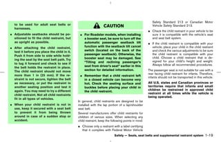
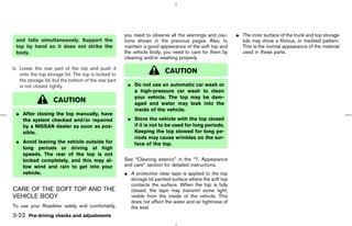
2nd 66 (106) To apply: pull the parking brake lever up k .
1
5th to 6th 33 (53) 3rd 95 (152) To release:
For quick acceleration in low altitude areas or in 4th — 1. Firmly apply the foot brake.
high altitude areas [over 4,000 ft (1,219 m)]: 5th —
6th — 2. Automatic transmission models:
Gear change MPH (km/h)
1st to 2nd 15 (24) Move the selector lever to the P (Park) posi-
tion.
2nd to 3rd 25 (40)
3rd to 4th 40 (64) Manual transmission models:
4th to 5th 45 (72) Place the shift lever in the N (Neutral) posi-
5th to 6th 50 (80) tion.
3. While pulling up on the parking brake lever
slightly, push the button k and lower the
2
lever completely k .
3
Starting and driving 5-15
੬ 07.7.25/Z33-D/V5.0 ੭](https://image.slidesharecdn.com/2008-350-z-120818113132-phpapp01/85/2008-350-z-OWNER-S-MANUAL-201-320.jpg)


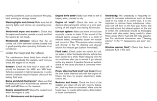
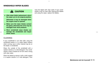
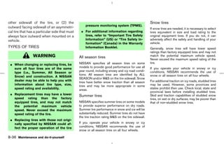
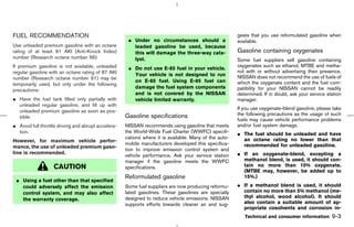
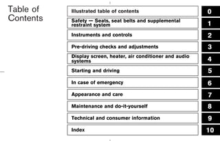
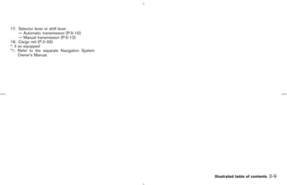
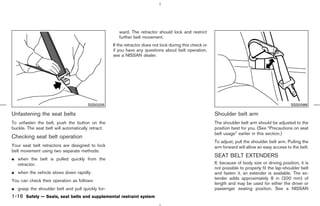
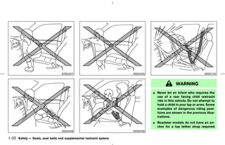
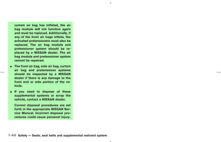
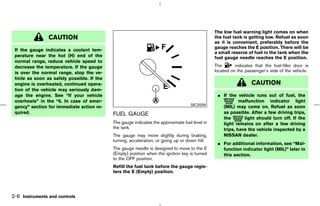
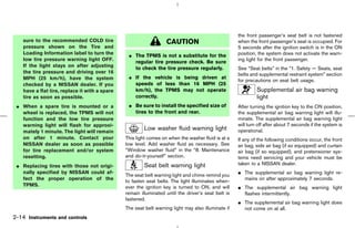
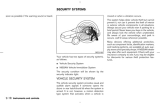
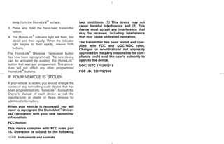
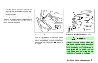
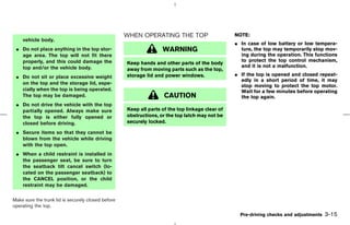
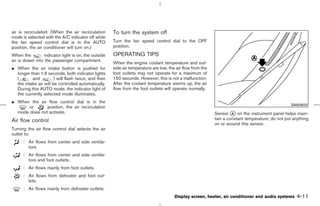
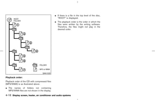
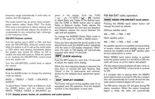
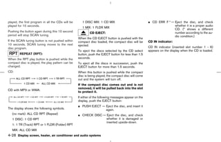
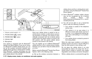
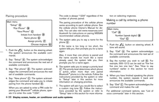
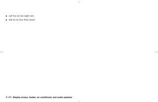
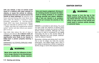
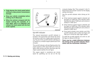
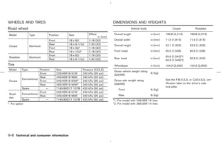
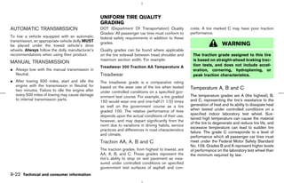
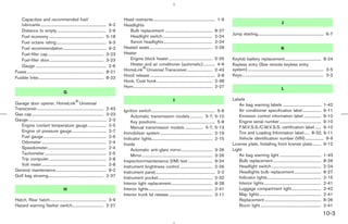
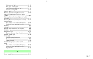
![SPECIFICATIONS
ENGINE
Model VQ35HR
Type Gasoline, 4-cycle
Cylinder arrangement 6-cylinder, V-slanted at 60°
Bore x Stroke in (mm) 3.760 x 3.205 (95.5 x 81.4)
Displacement cu in (cm3) 213.45 (3,498)
Firing order 1-2-3-4-5-6*1
Idle speed rpm
See the emission control label on the
Ignition timing (B.T.D.C.) degree/rpm
underside of the hood.
CO percentage at idle speed [No air] %
Spark plug Standard FXE22HR-11
Spark plug gap (Normal) in (mm) 0.043 (1.1) STI0425
*1: Cylinder number
Camshaft operation Timing chain
The spark ignition system of this vehicle meets all requirements of the Canadian
Interference-Causing Equipment Regulations.
Technical and consumer information 9-7
੬ 07.7.25/Z33-D/V5.0 ੭](https://image.slidesharecdn.com/2008-350-z-120818113132-phpapp01/85/2008-350-z-OWNER-S-MANUAL-283-320.jpg)


This owner's manual is designed to provide important information about operating and maintaining a Nissan vehicle, emphasizing safety precautions and the importance of reading the manual before usage. It details various vehicle features, warranty information, and maintains guidelines to ensure a safe driving experience. Additional resources for customer care and further assistance are also included within the manual.