Yarn type ImageStructural feature General character
Slub yarn Sudden change in yarn thickness
over short length
Weak, uneven texture, fancy look
Gimp yarn Crimpy in nature Weak, uneven texture, fancy look
Slub gimp Combination of change in yarn
thickness over short length and crimp
Weak, uneven texture, fancy look
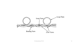
Loop yarn Projecting out loop at regular interval
from the core
Weak, uneven texture, fancy look
Snarl yarn Projecting out twisted yarn end from
the yarn body
Weak, uneven texture, fancy look
Chenille yarn Projecting out fibre ends from the
core
Weak, uneven texture, bulky in
appearance
Fancy yarns
R Chatopadhyay IITD 24 2
Slub yarn
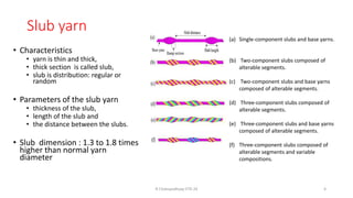
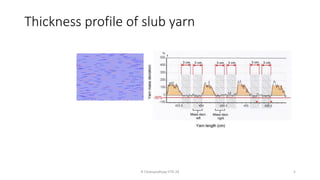
• Characteristics
•yarn is thin and thick,
• thick section is called slub,
• slub is distribution: regular or
random
• Parameters of the slub yarn
• thickness of the slub,
• length of the slub and
• the distance between the slubs.
• Slub dimension : 1.3 to 1.8 times
higher than normal yarn
diameter
R Chatopadhyay IITD 24 4
(a) Single-component slubs and base yarns.
(b) Two-component slubs composed of
alterable segments.
(c) Two-component slubs and base yarns
composed of alterable segments.
(d) Three-component slubs composed of
alterable segments.
(e) Three-component slubs and base yarns
composed of alterable segments.
(f) Three-component slubs composed of
alterable segments and variable
compositions.
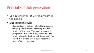
Principle of slubgeneration
• Computer control of Drafting system in
ring sinning
• Slub injection device
• It consists of a pair of roller driven aprons
which guide the sliver or roving into the
front drafting zone. The control system is
programmed to stop the aprons when the
front roller grip the injected fibres, with the
result that a fibre-tuft is pulled into the
main effect component.
R Chatopadhyay IITD 24 6
7.
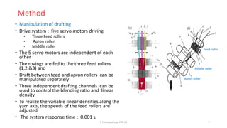
Method
• Manipulation ofdrafting
• Drive system : five servo motors driving
• Three Feed rollers
• Apron roller
• Middle roller
• The 5 servo motors are independent of each
other
• The rovings are fed to the three feed rollers
(1,2,&3) and
• Draft between feed and apron rollers can be
manipulated separately
• Three independent drafting channels can be
used to control the blending ratio and linear
density.
• To realize the variable linear densities along the
yarn axis, the speeds of the feed rollers are
adjusted
• The system response time : 0.001 s.
R Chatopadhyay IITD 24 7
Apron roller
Middle roller
Feed roller
8.
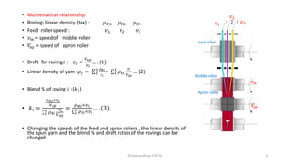
• Mathematical relationship
•Rovings linear density (tex) : 𝜌𝑅1, 𝜌𝑅2, 𝜌𝑅3
• Feed roller speed : 𝑣1, 𝑣2 𝑣3
• 𝑣𝑚 = speed of middle roller
• 𝑉
𝑎𝑝 = speed of apron roller
• Draft for roving 𝑖 : 𝑒𝑖 =
𝑉𝑎𝑝
𝑣𝑖
… . (1)
• Linear density of yarn :𝜌𝑦 = σ1
3 𝜌𝑅𝑖
𝑒𝑖
= σ1
3
𝜌𝑅𝑖
𝑣𝑖
𝑉𝑎𝑝
… (2)
• Blend % of roving 𝑖 : (𝑘𝑖)
• 𝑘𝑖 =
𝜌𝑅𝑖 ×𝑣𝑖
𝑉𝑎𝑝
σ1
3 𝜌𝑅𝑖
𝑣𝑖
𝑉𝑎𝑝
=
𝜌𝑅𝑖 ×𝑣𝑖
σ1
3 𝜌𝑅𝑖×𝑣𝑖
… . (3)
• Changing the speeds of the feed and apron rollers , the linear density of
the spun yarn and the blend % and draft ratios of the rovings can be
changed.
R Chatopadhyay IITD 24 8
𝑣𝑚
𝑉
𝑎𝑝
𝑣1
𝑣2
𝑣3
Middle roller
Feed roller
Apron roller
9.
• Yarn twist=
𝑆𝑝𝑖𝑛𝑑𝑙𝑒 𝑠𝑝𝑒𝑒𝑑
𝑦𝑎𝑟𝑛 𝑑𝑒𝑙𝑖𝑣𝑒𝑟𝑦 𝑠𝑝𝑒𝑒𝑑
=
𝑁𝑠𝑝
𝑣𝑑
• To realize the variable linear densities along the yarn axis, the speeds of
the feed rollers (𝑉𝑖 ) are altered periodically i.e.
Altered speed : 𝑉𝑖
′
= 𝑉𝑖 + ∆𝑉𝑖 periodically
• The linear density of slub yarn ∶ 𝜌′ = 𝜌𝑦0 + ∆𝜌𝑦
• ∆𝜌𝑦 = σ1
3
𝜌𝑅𝑖
∆𝑉𝑖
𝑉𝑎𝑝
[ rovings are same linear density]
• Where,
• 𝜌𝑦0 = linear density of the base yarn
• ∆𝜌 = the yarn linear density variation.
R Chatopadhyay IITD 24 9
Cui P, Xue Y, Liu Y. Manufacturing a ring spun slub yarn using multi-channel drafting
technique. Journal of Engineered Fibers and Fabrics. 2020;15. doi:10.1177/1558925020958518
10.
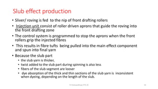
Slub effect production
•Sliver/ roving is fed to the nip of front drafting rollers
• Injection unit consist of roller driven aprons that guide the roving into
the front drafting zone
• The control system is programmed to stop the aprons when the front
rollers grip the injected fibres
• This results in fibre tufts being pulled into the main effect component
and spun into final yarn
• Because the slub part
• the slub yarn is thicker,
• twist added to the slub part during spinning is also less
• fibers of the slub segment are looser
• dye absorption of the thick and thin sections of the slub yarn is inconsistent
when dyeing, depending on the length of the slub.
R Chatopadhyay IITD 24 10
11.
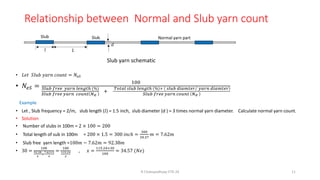
Relationship between Normaland Slub yarn count
• 𝐿𝑒𝑡 𝑆𝑙𝑢𝑏 𝑦𝑎𝑟𝑛 𝑐𝑜𝑢𝑛𝑡 = 𝑁𝑒𝑆
• 𝑁𝑒𝑆 =
100
𝑆𝑙𝑢𝑏 𝑓𝑟𝑒𝑒 𝑦𝑎𝑟𝑛 𝑙𝑒𝑛𝑔𝑡ℎ (%)
𝑆𝑙𝑢𝑏 𝑓𝑟𝑒𝑒 𝑦𝑎𝑟𝑛 𝑐𝑜𝑢𝑛𝑡 𝑁𝑒
+
𝑇𝑜𝑡𝑎𝑙 𝑠𝑙𝑢𝑏 𝑙𝑒𝑛𝑔𝑡ℎ % × Τ
𝑠𝑙𝑢𝑏 𝑑𝑖𝑎𝑚𝑡𝑒𝑟 𝑦𝑎𝑟𝑛 𝑑𝑖𝑎𝑚𝑡𝑒𝑟
𝑆𝑙𝑢𝑏 𝑓𝑟𝑒𝑒 𝑦𝑎𝑟𝑛 𝑐𝑜𝑢𝑛𝑡 𝑁𝑒
Example
• Let , Slub frequency = 2/m, slub length (𝑙) = 1.5 inch, slub diameter (d ) = 3 times normal yarn diameter. Calculate normal yarn count.
• Solution
• Number of slubs in 100m = 2 × 100 = 200
• Total length of sub in 100m = 200 × 1.5 = 300 𝑖𝑛𝑐ℎ =
300
39.37
𝑚 = 7.62𝑚
• Slub free yarn length =100𝑚 − 7.62𝑚 = 92.38𝑚
• 30 =
100
92.38
𝑥
+
7.62×3
𝑥
=
100
115.24
𝑥
, 𝑥 =
115.24×30
100
= 34.57 (𝑁𝑒)
R Chatopadhyay IITD 24 11
Slub yarn schematic
Slub Slub
𝑙 𝐿
𝑑
Normal yarn part
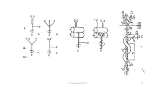
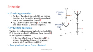
Principle
• 1st twistingoperation
• Fig 1 a. : Two basic threads ( G) are twisted
together and thereafter wound around with
one or more decorative thread Z
• Fig. 1 b: Decorative thread (Z) is twisted into
two basic threads G twisted together.
• 2nd twisting operation
• Twisted threads produced by both methods ( G +
Z) is then twisted with additional fixing thread(F)
in the opposite direction.
• If the rate of delivery of fixing thread (F) is
greater than twisted roving , it is wound
around (G+Z) by this thread ( II b )
• Fancy twisted yarns E are obtained
R Chatopadhyay IITD 24 13
1st twisting
stage
2nd twisting
stage
Z
Z
F
F
14.
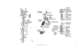
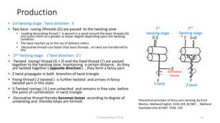
Production
• 1st twistingstage: Twist direction : S
• Two basic roving /threads (G) are passed to the twisting zone
• Leading decorating thread Z is wound in a spiral around the basic threads (G)
and covers them to a greater or lesser degree depending upon the twisting
condition.
• The twist reaches up to the nip of delivery rollers
• Decorative thread runs faster than basic threads , no twist are transferred to
this.
• 2nd Twisting stage: ( Twist direction : Z )
• Twisted roving/ thread (G + Z) and the fixed thread (F) are passed
together to the twisting zone maintaining a certain distance . As they
are twisted together ( opposite direction ) , they form a fancy yarn
• Z twist propagate in both branches of twist triangle.
• Fixing thread ( Z twisted ) is further twisted and arrives in fancy
twisted yarn in this state.
• S-Twisted rovings ( G ) are untwisted and remains in free sate before
the point of combination in twist triangle
• Decorative thread thereby becomes looser according to degree of
untwisting and thereby loops are formed.
R Chatopadhyay IITD 24 14
1st
twisting stage
2nd
Twisting stage
S twist Z twist
Z
F
Decorative
thread
Theoretical principles of fancy yarn twisting: by Erich
Marton, Melliand English, E242-243, 8/1987 , Melliand
Textileberichte 8/1987, P546- 550
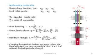
• Mathematical relationship
•Rovings linear densities ( tex) : ρb1, ρb2, ρb3
• Feed roller speeds : Vb1, Vb2, Vb3.
• 𝑉
𝑚 = speed of middle roller
• 𝑉𝑓 = speed of apron roller
• Draft for roving 𝑖 : 𝑒𝑖 =
𝑉𝑓
𝑉𝑏𝑖
… . (1)
• Linear density of yarn : ρ = σ1
3 𝜌𝑏𝑖
𝑒𝑖
= σ1
3
𝜌𝑏𝑖
𝑉𝑏𝑖
𝑉𝑓
… (2)
•
• Blend % of roving 𝑖 : 𝑘𝑖 =
𝜌𝑏𝑖𝑉𝑏𝑖
𝜌
=
𝜌𝑏𝑖𝑉𝑏𝑖
σ1
3 𝜌𝑏𝑖𝑉𝑏𝑖
… . (3)
• Changing the speeds of the feed and apron rollers , the
linear density of the spun yarn and the blend % and draft
ratios of the rovings can be changed.
R Chatopadhyay IITD 24 24
𝑣𝑚
𝑣𝑓
𝑣𝑏1
𝑣𝑏2
𝑣𝑏3
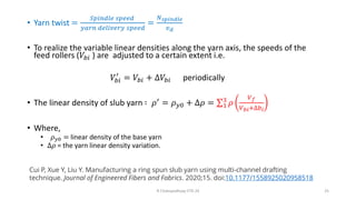
25.
• Yarn twist=
𝑆𝑝𝑖𝑛𝑑𝑙𝑒 𝑠𝑝𝑒𝑒𝑑
𝑦𝑎𝑟𝑛 𝑑𝑒𝑙𝑖𝑣𝑒𝑟𝑦 𝑠𝑝𝑒𝑒𝑑
=
𝑁𝑠𝑝𝑖𝑛𝑑𝑙𝑒
𝑣𝑑
• To realize the variable linear densities along the yarn axis, the speeds of the
feed rollers (𝑉𝑏𝑖 ) are adjusted to a certain extent i.e.
𝑉𝑏𝑖
′
= 𝑉𝑏𝑖 + ∆𝑉𝑏𝑖 periodically
• The linear density of slub yarn ∶ 𝜌′
= 𝜌𝑦0 + ∆𝜌 = σ1
3
𝜌
𝑉𝑓
𝑉𝑏𝑖+∆𝑏𝑖
• Where,
• 𝜌𝑦0 = linear density of the base yarn
• ∆𝜌 = the yarn linear density variation.
R Chatopadhyay IITD 24 25
Cui P, Xue Y, Liu Y. Manufacturing a ring spun slub yarn using multi-channel drafting
technique. Journal of Engineered Fibers and Fabrics. 2020;15. doi:10.1177/1558925020958518


![• Yarn twist =
𝑆𝑝𝑖𝑛𝑑𝑙𝑒 𝑠𝑝𝑒𝑒𝑑
𝑦𝑎𝑟𝑛 𝑑𝑒𝑙𝑖𝑣𝑒𝑟𝑦 𝑠𝑝𝑒𝑒𝑑
=
𝑁𝑠𝑝
𝑣𝑑
• To realize the variable linear densities along the yarn axis, the speeds of
the feed rollers (𝑉𝑖 ) are altered periodically i.e.
Altered speed : 𝑉𝑖
′
= 𝑉𝑖 + ∆𝑉𝑖 periodically
• The linear density of slub yarn ∶ 𝜌′ = 𝜌𝑦0 + ∆𝜌𝑦
• ∆𝜌𝑦 = σ1
3
𝜌𝑅𝑖
∆𝑉𝑖
𝑉𝑎𝑝
[ rovings are same linear density]
• Where,
• 𝜌𝑦0 = linear density of the base yarn
• ∆𝜌 = the yarn linear density variation.
R Chatopadhyay IITD 24 9
Cui P, Xue Y, Liu Y. Manufacturing a ring spun slub yarn using multi-channel drafting
technique. Journal of Engineered Fibers and Fabrics. 2020;15. doi:10.1177/1558925020958518](https://image.slidesharecdn.com/2-slubandfancyyarn-250319103938-7dfbb678/85/2-Slub-and-fancy-yarn-description-how-it-work-9-320.jpg)
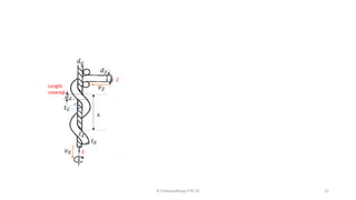
![Twisting process
• Threads have circular X section
• 𝑡𝐺
′
= twist in basic thread before delivery
• 𝑡𝐺 = twist in basic thread in twisted yarn
• 𝑣𝐺= feed speed to twisting point
• 𝑣𝐸= delivery speed of yarn
• 𝑣𝐸 < 𝑣𝐺
• 𝑣𝑍 = speed of feeding decorative thread
• Twist in fancy twisted yarn (𝑡𝐸)
𝑡𝐸 =
𝑛
𝑣𝐸
… (1)
• Twist in the basic thread reduces to
𝑡𝐺 = 𝑡𝐺
′
− 𝑡𝐸 = 𝑡𝐺
′
−
𝑛
𝑉𝐸
… (2) [ opposite twist direction]
R Chatopadhyay IITD 24 16
G G
ℎ
𝑣𝐺 𝑣𝐺
𝑣𝐸
𝑣𝑍
𝑑𝐺
Z
𝑡𝐺
𝑡𝑍
𝑡𝐸
𝑑𝐺
′
𝑑𝐺
′
𝑡𝐺
′
E](https://image.slidesharecdn.com/2-slubandfancyyarn-250319103938-7dfbb678/85/2-Slub-and-fancy-yarn-description-how-it-work-16-320.jpg)
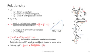
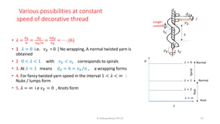
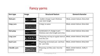
![Degree of cover by decorative thread
• 𝑑𝐺
′
= diameter of basic thread , 𝑑𝑍 = diameter of decorative thread
• 𝑡𝑍 = twist in decorative thread
• Degree of cover
length of basic thread covered by coils of decorative thread to its
total length:
• 𝜆 =
𝑑𝑍
ℎ
=
𝑑𝑍
Τ
𝑣𝐸 𝑛
=
𝑛𝑑𝑍
𝑣𝐸
= ⋯ . (6)
• 𝜆 = 1 → 𝑑𝑧 = ℎ 𝑂𝑟 Τ
𝑣𝐸 𝑛 : wrapping would be obtained
• 𝜆 < 1 → 𝑑𝑧 < ℎ = Τ
𝑣𝐸 𝑛 ( form spiral)
• 𝜆 > 1 : nubs/lump
• 𝜆 = ∞ : knots [ since 𝑣𝐸= 0]
• 𝜆 = 2 𝑜𝑟 3 : a two/ three layered wrapping is obtained
• As 𝜆 increases , the last wrapping layer is incompletely formed, and it
gives an uneven appearance.
𝑙𝑧
𝜋 𝑑𝐺 + 𝑑𝑍
ℎ
G G
ℎ
𝑣𝐺 𝑣𝐺
𝑣𝐸
𝑣𝑍
𝑑𝐺
Z
𝑡𝐺
𝑡𝑍
𝑡𝐸
𝑑𝐺
′
𝑑𝐺
′
𝑡𝐺
′
E
𝑑𝑍
Length
covered
𝑑𝑍
R Chatopadhyay IITD 24 18](https://image.slidesharecdn.com/2-slubandfancyyarn-250319103938-7dfbb678/85/2-Slub-and-fancy-yarn-description-how-it-work-18-320.jpg)