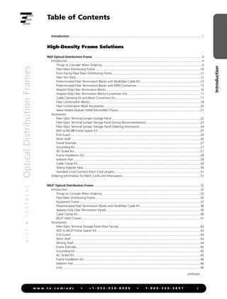
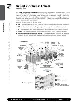
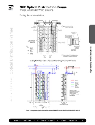
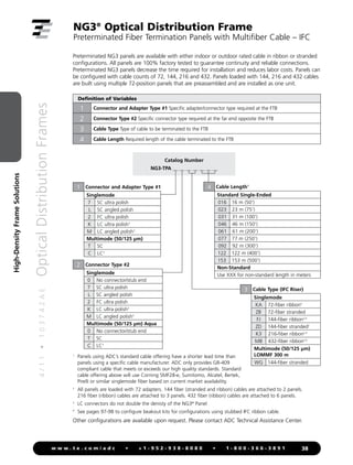
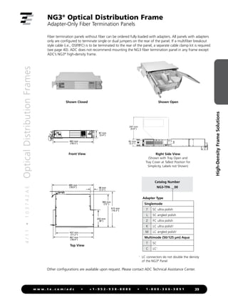
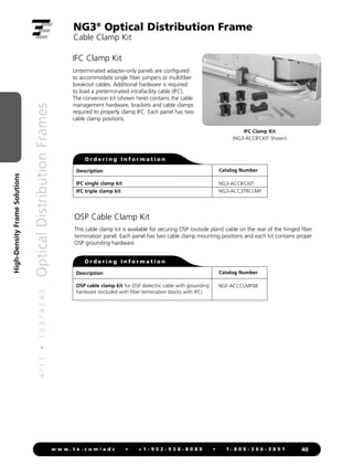
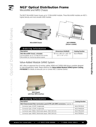
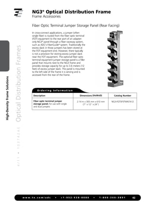
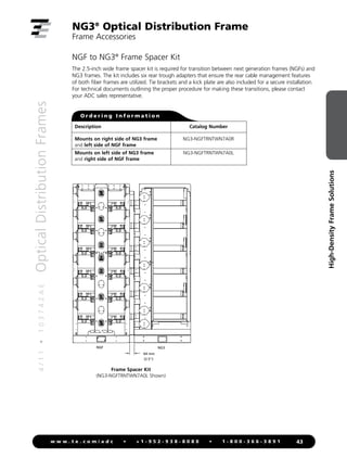
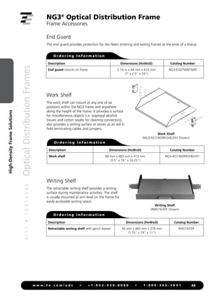
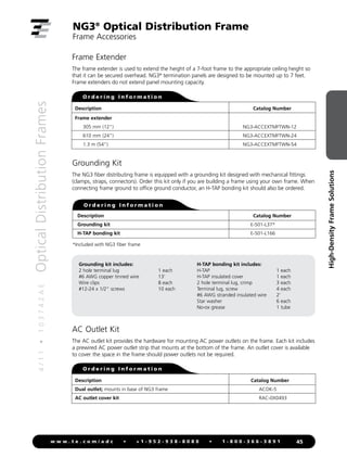
SlideShare a Scribd company logo
1 of 113
Download to read offline
Optical Distribution Frames
3rd Edition
4
/
1
1
•
1
0
3
7
4
2
A
E
Optical
Distribution
Frames
Introduction
i
w w w . t e . c o m / a d c • + 1 - 9 5 2 - 9 3 8 - 8 0 8 0 • 1 - 8 0 0 - 3 6 6 - 3 8 9 1
Table of Contents
Introduction.............................................................................................................................................................1
High-Density Frame Solutions
NGF Optical Distribution Frame..................................................................................................................................4
Introduction...............................................................................................................................................................4
Things to Consider When Ordering......................................................................................................................6
Fiber Main Distributing Frame............................................................................................................................10
Front Facing Fiber Main Distributing Frame.........................................................................................................11
Fiber Slim Rack...................................................................................................................................................12
Preterminated Fiber Termination Blocks with Multifiber Cable-IFC.......................................................................13
Preterminated Fiber Termination Blocks with MPO Connectors...........................................................................15
Adapter-Only Fiber Termination Blocks...............................................................................................................16
Adapter-Only Fiber Termination Blocks-Conversion Kits......................................................................................17
Cable Clamping Kit and Block Conversion Kit.....................................................................................................17
Fiber Combination Blocks...................................................................................................................................18
Fiber Combination Block Accessories..................................................................................................................20
Value-Added Module (VAM) MicroVAM Chassis.................................................................................................21
Accessories
Fiber Optic Terminal Jumper Storage Panel.........................................................................................................22
Fiber Optic Terminal Jumper Storage Panel Zoning Recommendations................................................................23
Fiber Optic Terminal Jumper Storage Panel Ordering Information........................................................................24
NGF to NG3® Frame Spacer Kit.........................................................................................................................25
End Guard.........................................................................................................................................................26
Work Shelf.........................................................................................................................................................26
Frame Extender..................................................................................................................................................27
Grounding Kit....................................................................................................................................................27
AC Outlet Kit.....................................................................................................................................................27
Frame Installation Kit..........................................................................................................................................28
Isolation Pad......................................................................................................................................................28
Cable Clamp Kit.................................................................................................................................................29
Sliding Adapter Pack..........................................................................................................................................30
Standard Cross-Connect Patch Cord Lengths......................................................................................................31
Ordering Information for Patch Cords and Attenuators............................................................................................31
NG3®
Optical Distribution Frame..............................................................................................................................32
Introduction.............................................................................................................................................................32
Things to Consider When Ordering....................................................................................................................33
Fiber Main Distributing Frame............................................................................................................................36
Equipment Frame...............................................................................................................................................37
Preterminated Fiber Termination Panels with Multifiber Cable-IFC.......................................................................38
Adapter-Only Fiber Termination Panels...............................................................................................................39
Cable Clamp Kit.................................................................................................................................................40
NG3®
VAM Chassis.............................................................................................................................................41
Accessories
Fiber Optic Terminal Storage Panel (Rear Facing).................................................................................................42
NGF to NG3®
Frame Spacer Kit...........................................................................................................................43
End Guard.........................................................................................................................................................44
Work Shelf.........................................................................................................................................................44
Writing Shelf......................................................................................................................................................44
Frame Extender..................................................................................................................................................45
Grounding Kit....................................................................................................................................................45
AC Outlet Kit.....................................................................................................................................................45
Frame Installation Kit..........................................................................................................................................46
Isolation Pad......................................................................................................................................................46
Lock...................................................................................................................................................................46
continues…
4
/
1
1
•
1
0
3
7
4
2
A
E
Optical
Distribution
Frames
Introduction
ii
w w w . t e . c o m / a d c • + 1 - 9 5 2 - 9 3 8 - 8 0 8 0 • 1 - 8 0 0 - 3 6 6 - 3 8 9 1
Table of Contents
Sliding Adapter Pack..........................................................................................................................................47
Standard Cross-Connect Patch Cord Lengths......................................................................................................48
Ordering Information for Patch Cords and Attenuators............................................................................................48
Traditional Frame Solutions
8-Inch FCM Optical Distribution Frame....................................................................................................................49
Introduction.............................................................................................................................................................50
Things to Consider When Ordering....................................................................................................................51
Fiber Main Distributing Frame (Rear Load)..........................................................................................................53
Preterminated Fiber Termination Panels with Multifiber Cable-IFC.......................................................................54
Adapter-Only Fiber Termination Panels...............................................................................................................55
Splice Panels......................................................................................................................................................56
Value-Added Module (VAM) Chassis..................................................................................................................57
Accessories
Interbay Management Panel...............................................................................................................................58
Fiber Optic Terminal Storage Panel (Rear Facing).................................................................................................58
End Guard.........................................................................................................................................................58
Guard Box (Under Floor).....................................................................................................................................60
Frame Installation Kit..........................................................................................................................................61
Horizontal Cable Trough.....................................................................................................................................63
Frame Filler Plate................................................................................................................................................63
AC Outlet Kit and Raceway................................................................................................................................64
Rack Extenders...................................................................................................................................................64
Grounding Kit....................................................................................................................................................65
Vertical Cable Guide (VCG) Kit...........................................................................................................................66
Blank Panel........................................................................................................................................................66
Cable Clamp Kit and Dual Cable Clamp Kit........................................................................................................66
Assembled Splice Tray and Chip.........................................................................................................................67
Splice Protector Sleeve........................................................................................................................................67
Standard Cross-Connect Patch Cord Lengths......................................................................................................68
Ordering Information for Patch Cords and Attenuators............................................................................................68
LSX Optical Distribution Frame.................................................................................................................................69
Introduction.............................................................................................................................................................69
Things to Consider When Ordering....................................................................................................................70
High-Density Distribution Frame Solution (using 288-Termination-Only panel)....................................................71
High-Density Distribution Frame Solution (using 288-Termination/Splice panel)...................................................72
Homerun Splitter Solution..................................................................................................................................73
Traditional LSX Universal Fiber Distributing Frame Solution.................................................................................74
Preterminated Fiber Termination Panels with Multifiber Cable.............................................................................75
Adapter-Only Fiber Termination Panels...............................................................................................................76
Preterminated Fiber Termination/Splice Panels with Pigtails.................................................................................77
Splice Panels......................................................................................................................................................79
LGX®
Compatible Value-Added Module (VAM) Chassis.......................................................................................80
4
/
1
1
•
1
0
3
7
4
2
A
E
Optical
Distribution
Frames
Introduction
iii
w w w . t e . c o m / a d c • + 1 - 9 5 2 - 9 3 8 - 8 0 8 0 • 1 - 8 0 0 - 3 6 6 - 3 8 9 1
Table of Contents
Accessories
Frame Installation Kit..........................................................................................................................................81
Interbay Management Panel...............................................................................................................................83
End Guard.........................................................................................................................................................83
AC Outlet Kit and Raceway................................................................................................................................84
Rack Extenders...................................................................................................................................................84
Splice Tray..........................................................................................................................................................85
Cable Clamp Kit.................................................................................................................................................85
Cable Ring Kit....................................................................................................................................................85
Standard Cross-Connect Patch Cord Lengths......................................................................................................85
Ordering Information for Patch Cords and Attenuators.......................................................................................85
Adapter Pack.....................................................................................................................................................86
Cabinet Solutions
Fiber Splice Cabinets..................................................................................................................................................88
Accessories.................................................................................................................................................................89
Splice Enclosure Solutions
Fiber Entrance Cabinet..............................................................................................................................................92
Introduction.......................................................................................................................................................92
Cabinet Solutions...............................................................................................................................................92
Accessories
Cable Clamping Kit............................................................................................................................................93
Splice Tray..........................................................................................................................................................93
Breakout Kit for Ribbon in Loose Buffer Tube (RLBT) OSP Cable..........................................................................94
Breakout Kit for Ribbon Central Tube (RCT) OSP Cable.......................................................................................95
RCT Breakout Kit Typical Configurations.............................................................................................................96
Breakout Kit for Intrafacility (IFC) Ribbon Cables.................................................................................................97
IFC Breakout Kit Typical Configurations..............................................................................................................98
Protective Tubing Cutting Tool............................................................................................................................99
Grounding Kit....................................................................................................................................................99
Splice Protector Sleeve......................................................................................................................................100
Grounding/Moisture Blocking Kits....................................................................................................................100
Cable Assembly Solutions
Cable Assembly Solutions.......................................................................................................................................103
Introduction...........................................................................................................................................................103
Tracerlight®
Connector Identification System (Power Source and Patch Cords)..................................................104
Tracerlight Singlemode or Multimode Patch Cords...........................................................................................105
Singlemode Patch Cords..................................................................................................................................106
Multimode Patch Cords...................................................................................................................................107
In-Line Attenuators..........................................................................................................................................108
Index.........................................................................................................................................................................109
4
/
1
1
•
1
0
3
7
4
2
A
E
Optical
Distribution
Frames
Introduction
1
w w w . t e . c o m / a d c • + 1 - 9 5 2 - 9 3 8 - 8 0 8 0 • 1 - 8 0 0 - 3 6 6 - 3 8 9 1
Enabling the Next Generation of High-Speed Networks
Lower operations costs, greater reliability and flexibility in service offerings, quicker deployment of new
and upgraded services — these are the characteristics of a successful service provider in a competitive,
global market.
As high-bandwidth networks such as SONET and FTTX are built, far more fiber is required. But
deploying fiber is not enough; a successful fiber network also requires a well-designed infrastructure
based on solid fiber management fundamentals. Management of fiber cables has a direct impact on
network reliability, performance and cost. It impacts network maintenance and operations, as well as
the ability to reconfigure, expand the network and implement new services.
The ADC family of Optical Distribution Frame (ODF) solutions delivers the crucial elements
of fiber cable management: connector and cable accessibility, bend radius protection, cable routing
paths and physical protection. If these elements are executed correctly, the network can deliver its full
competitive advantages.
• Connector and Cable Access: Allowing easy
access to connectors and installed fibers is
critical in maintaining proper bend radius
protection. ODF products ensure that any
fiber can be installed or removed without
inducing a macrobend on an adjacent fiber.
The accessibility provided by features such as
sliding adapter packs can have a significant
impact on network reconfiguration time.
Accessibility is most critical during network
reconfiguration operations and directly impacts
operation costs and network reliability.
• Bend Radius Protection: Simply put, optimal
signal flow ensures network performance and
reliability. ADC’s ODF products ensure that the
proper bend radius is maintained to prevent
attenuation and deliver the highest possible
performance as well as long-term reliability.
Note: Reduced bend radius cable solutions,
while offering a tighter bend radius, are not a
substitute for well-engineered cable management.
• Cable Routing Paths: Improper technician
routing of fibers is one of the major causes
of bend radius violations. ODF products are
extremely craft friendly, providing routing paths
that are clearly defined and easy to follow
—leaving no room for guesswork and ensuring
that technicians can easily trace and locate fibers.
• Physical Protection: All fibers should be
protected throughout the network from
accidental damage by technicians and
equipment. Fibers routed between pieces
of equipment without proper protection are
susceptible to damage, which can critically
impact network reliability. ADC’s robust fiber
cable management technology ensures that every
fiber is well protected and designed to withstand
daily wear and tear.
Optical Distribution Frames
Introduction
4
/
1
1
•
1
0
3
7
4
2
A
E
Optical
Distribution
Frames
Introduction
2
w w w . t e . c o m / a d c • + 1 - 9 5 2 - 9 3 8 - 8 0 8 0 • 1 - 8 0 0 - 3 6 6 - 3 8 9 1
Fiber Raceway
Solutions
(FGS)
Splice Vault
Cable Entrance
Solutions
(FEC)
High-Density
FDF Lineup
Solutions
(NGF, NG3)
FL1000 Wallbox
FiberGuide
Express Exit™
Traditional
FDF Lineup
Solutions
(8" FCM, LSX)
Intermediate FDF Solutions
(8" FCM)
FL2000
Panel
FiberGuide®
Flex Tubing
RiserGuide Vertical
FiberGuide
FPL
Panel
FMT
Panel
Fiber Optic
Transport Lineup
Fiber Optic
Panel Solutions
(FOP)
Fiber Cable Assembly
& Connector Solutions
(FCC)
Value-Added Module
(VAM) Solutions
(Monitors, Splitters, WDM, CWDM)
24"
12"
12"
12"
6"
6"
6"
6"
6"
6"
Level 3
FL1000 Wall Box
Plenum FiberGuide®
Level 2
FL2000 Wall Mount Panel
Plenum FiberGuide
Level 1
OMX600®
Fiber Distribution
Frame, Plenum FiberGuide, VAMs
Customer Premises
Central Office
ADC’s Next Generation Frame (NGF) is the industry-leading high-density fiber management solution,
accommodating the rapid growth and expansion of the fiber network while reducing jumper pile-up in
horizontal troughs. The ability to easily access connectors and manage fiber cables has a direct impact
on network reliability, performance and cost. As networks require expansion, reconfiguration and
implementation of new services to the end customer, ADC’s NGF is a versatile solution that will satisfy
network requirements for years to come.
Additional solutions in the ODF portfolio include:
• NG3®
– Telecordia®
GR-449-CORE-Issue 2 compliant frame solution, providing up to 1,440 terminations
• FCM – traditional frame solution utilizing an angled retainer design for better cable management
• LSX – industry-standard frame solution that consists of panels loaded with straight adapter technology
• OMX600®
– versatile cabinet solution that incorporates termination, splicing and storage demands
• Fiber Cable Assembly and Accessory Products – a comprehensive line of patch cords, IFC assemblies,
attenuators, FasTerm®
connectors and adapters to meet the demanding needs of today’s network
Optical Distribution Frames
Introduction
4
/
1
1
•
1
0
3
7
4
2
A
E
Optical
Distribution
Frames
3
w w w . t e . c o m / a d c • + 1 - 9 5 2 - 9 3 8 - 8 0 8 0 • 1 - 8 0 0 - 3 6 6 - 3 8 9 1
High-Density
Frame
Solutions
High-Density Frame Solutions
NGF Optical Distribution Frame
Introduction........................................................................ 4
Things to Consider When Ordering..................................... 6
Frames.............................................................................. 10
Termination Blocks............................................................ 13
Combination Blocks.......................................................... 18
Value-Added Module (VAM) Chassis................................. 21
Accessories....................................................................... 22
Standard Cross-Connect Patch Cord Lengths.................... 31
NG3®
Optical Distribution Frame
Introduction...................................................................... 32
Things to Consider when Ordering................................... 33
Frames.............................................................................. 36
Termination Panels............................................................ 38
Value-Added Module (VAM) Chassis................................. 41
Accessories....................................................................... 42
Standard Cross-Connect Patch Cord Lengths.................... 48
4
/
1
1
•
1
0
3
7
4
2
A
E
Optical
Distribution
Frames
4
w w w . t e . c o m / a d c • + 1 - 9 5 2 - 9 3 8 - 8 0 8 0 • 1 - 8 0 0 - 3 6 6 - 3 8 9 1
High-Density
Frame
Solutions
Frame
ADC’s next generation frame (NGF) product line has fiber frames
designed to fit a variety of network applications. Each frame option is
designed with an emphasis on superior cable management and ease
of use, including features such as ample trough space for cable and
jumpers, easy access to connectors and storage for jumpers. The frame
sections are shipped from the factory fully equipped with all cable
management hardware including integrated jumper slack storage.
Fiber Termination Block (FTB)
ADC’s FTB is available with industry-standard adapters in block configurations of 72-, 96- and
144-positions. Also, a 192-position FTB is available using LC adapters. FTBs utilize sliding adapter
packs to gain easy access to both the front and rear terminations. To accommodate varying network
requirements and speed installation, FTBs can be ordered with adapters only or preterminated with
either intrafacility cable (IFC) or outside plant (OSP) cables.
Fiber Combination Block (FCB)
Our FCB provides termination and on-frame splicing capabilities. This configuration occupies two
mounting positions on the frame section. They are available with industry-standard adapters in
block configurations of 72-, 96- and 144-positions. An FCB with 192-positions is also available
using LC adapters.
Value-Added Module Block (VAM)
Adding signal management and enhancement functions, such as splitters, couplers and wavelength
division multiplexers, optimizes the value of your fiber network, by providing nonintrusive access to
the optical signal for monitoring and testing signal integrity. There is a block configuration available to
accommodate Micro Value-Added Modules (MicroVAMs) for applications requiring splitters or WDMs.
Fiber Optic Terminal Storage Panel
ADC’s fiber optic terminal storage panel is used as a storage apparatus for up to 16 feet of equipment
(FOT) jumpers at the fiber frame lineup. This panel can be installed between fiber frames and at the
end of a lineup.
NGF Optical Distribution Frame
Introduction
4
/
1
1
•
1
0
3
7
4
2
A
E
Optical
Distribution
Frames
5
w w w . t e . c o m / a d c • + 1 - 9 5 2 - 9 3 8 - 8 0 8 0 • 1 - 8 0 0 - 3 6 6 - 3 8 9 1
High-Density
Frame
Solutions
NGF Optical Distribution Frame
Introduction
Product Overview
Recommended applications Medium to large fiber count applications or any space constrained
applications. Highest fiber count solution available.
Description High-density solution using 72-, 96-, 144- and 192-position
blocks (FTB)
Number of fibers,
future growth potential
Up to 29,177 in 17 frames using 144-position blocks,
SC connectors and 1.7 mm patch cords
Up to 32,939 in 15 frames using 192-position blocks,
LC connectors and 1.7 mm patch cords
Interconnect Good
Cross-connect Excellent
Accommodates on-frame splicing Good
Accommodates off-frame splicing Excellent
Density – terminations per frame 1,728 terminations using standard connectors;
2,304 terminations using LC connectors
Front access to rear connector Yes
VAM capabilities Yes. Separate panel required
Slack storage location On-frame (integrated jumper slack storage)
Connector access Sliding adapter pack
4
/
1
1
•
1
0
3
7
4
2
A
E
Optical
Distribution
Frames
6
w w w . t e . c o m / a d c • + 1 - 9 5 2 - 9 3 8 - 8 0 8 0 • 1 - 8 0 0 - 3 6 6 - 3 8 9 1
High-Density
Frame
Solutions
Frame Capacity Requirements (Important Facts on Trough Space)
144 FTB
(1,728/frame)
96 FTB
(1,152/frame)
72 FTB
(864/frame)
NGF 12 frames 18 frames 24 frames
Front Facing NGF 4 frames 6 frames 8 frames
Calculation assumptions:
- Per Telecordia®
GR-449-CORE, Issue 2 requirements
- 2.0 mm jumpers (maximum recommended diameter for all NGF products)
- 2" maximum jumper pile
- 50% of jumpers do not appear at any given place in lineup (50% rule)
Frame Lineup Capacity Comparisons
2.0 mm Jumpers/Maximum Recommended Diameter for NGF Products
NGF Frame:
1,728 Fiber Terminations
Conventional Frame:
1,152 Fiber Terminations
Conventional Frame:
648 Fiber Terminations
Horizontal trough space
Maximum number of
terminations allowed in
a frame lineup before
exceeding 2" pileup
30"
21,081
10" (5" Upper and Lower)
8,240
5" Lower
4,120
NGF Frame Considerations
NGF Frame Front Facing NGF Frame Slim Rack
Flexibility/ability to grow frame lineup Yes Yes No
Interconnect Supports Supports Supports
Cross-connect Supports Supports Supports
On-frame splicing Supports Supports Supports
Off-frame splicing Supports Supports Supports
Rear access required Yes No No
All front access No Yes Yes
Footprint
30" Wide x
24" Deep
30" Wide x
19" Deep
19" Wide x
19" Deep
Horizontal trough space available 30" 9" N/A
Block and Frame Termination Capacity
NGF Block Termination Capacity NGF Frame Termination Capacity Min/Max Patch Cord Diameter
72 864 2.0
96 1,152 2.0
144 1,728 2.0
192 (LC connectors only) 2,304 1.7
NGF Optical Distribution Frame
Things to Consider When Ordering
4
/
1
1
•
1
0
3
7
4
2
A
E
Optical
Distribution
Frames
7
w w w . t e . c o m / a d c • + 1 - 9 5 2 - 9 3 8 - 8 0 8 0 • 1 - 8 0 0 - 3 6 6 - 3 8 9 1
High-Density
Frame
Solutions
Zoning Recommendations
NOTE : Equipment Jumpers Should be Populated from the
Bottom Block Position-Up and The OSP Blocks Should
be Deployed From The Top Block Position-Down.
FOTSB -
FTB -
IFC -
Fiber Optic
Terminal
Storage Bay
Fiber
Terminal
Block
Intrafacility
Fiber Cable NGF FRAME
FOTSB
Equipment
Jumper from
Equipment Optical
1
IFC
FOTSB
Fibers are Fanned Out and
Terminated to the Back
Side of the Adapters on
the Sliding Adapter Packs
1
IFC
FIBER TERMINAL
BLOCK DETAIL
Routing is Down
The Inside Back
of the Fiber
Terminal Block
Equipment Patch
Cord From FOT
Storage Bay
NOTE : Radius Limiters On FOTSB are
Removed at these Six Locations
to Allow IFC to Pass into FTB's.
1
KEY:
See Fiber Terminal
Block (FTB) Detail
Cable Clamp And Block
Conversion Kit Required
When Bringing Cable Into
Adapter Only Block
Left
Vertical
Right
Vertical
Side View
2.00"
19.00"
30.00"
(Shown W/EG Removed)
5.00"
52.00"
84.00"
IFC Cable
EQT Jumper
to FTB Rear
Cross-connect
Jumper
EQT Jumper
to FTB Front
Front View
OSP
MVAM
FTB
KEY
OSP - OSP Pre-term Block
MVAM - FRT & RR Access Microvam
FGS - Fiberguide System
NGF - Next Generation Frame
FTB - Fiber Term Block
FOTSB - F/O Terminal Storage Bay
EG - End Guard
MVAM - Microvam
12.00"
FOTSB EG
EG
NGF
FGS
NGF Optical Distribution Frame
Things to Consider When Ordering
Routing Multi-Fiber Cable & Fiber Patch Cords Together Into NGF Vertical
Front Facing NGF Application with Front and Rear Access MicroVAM Terminal Blocks
4
/
1
1
•
1
0
3
7
4
2
A
E
Optical
Distribution
Frames
8
w w w . t e . c o m / a d c • + 1 - 9 5 2 - 9 3 8 - 8 0 8 0 • 1 - 8 0 0 - 3 6 6 - 3 8 9 1
High-Density
Frame
Solutions
Zoning Recommendations
NGF Optical Distribution Frame
Things to Consider When Ordering
Side View
2.00"
30.00"
(Shown W/EG Removed)
5.00"
40.00"
84.00"
IFC Cable
Cross-connect
JUMPER
EQT Jumper
to FTB Front
Front View
OSP SPLTR
KEY
OSP - OSP Pre-term Block
SPLTR - Front Access Splitter Block
FGS - Fiberguide System
NGF - Next Generation Frame
FTB - Fiber Term Block
FOTSB - F/O Terminal Storage Bay
EG - End Guard
PON - Passive Optical Network
EG
NGF
FGS
19.00"
EG
FOTSB FOTSB
OSP
30.00"
84.00"
IFC Cable
Equipment Jumper
Cross-connect Jumper
KEY
EQT - Equipment Terminations
FOTSB - Fiber Optic Terminal Storage Bay
FGS - Fiberguide System
NGF - Next Generation Frame
OSP - Outside Plant Terminations
12.00"
EQT EQT EQT
FGS
EQT OSP
124.00"
Pre-Terminated Block
Adapter Only Block
NGF FRAME 1 NGF FRAME 2 NGF FRAME 3
Front Facing NGF PON Splitter Block Application
NGF Cross-Connect Application with Equipment Jumper Storage
4
/
1
1
•
1
0
3
7
4
2
A
E
Optical
Distribution
Frames
9
w w w . t e . c o m / a d c • + 1 - 9 5 2 - 9 3 8 - 8 0 8 0 • 1 - 8 0 0 - 3 6 6 - 3 8 9 1
High-Density
Frame
Solutions
NGF Optical Distribution Frame
Things to Consider When Ordering
How to Order
Main Components of the NGF Catalog Number Quantity
1) Select the desired Frame based on application
- Fiber Main Distributing Frame - Page 10 ___________________ ______
- Front Facing Fiber Main Distributing Frame - Page 11 ___________________ ______
- Fiber Slim Rack - Page 12 ___________________ ______
2) Select the desired Fiber Termination Blocks
- Preterminated Fiber Termination Blocks with
Multifiber Cable-IFC - Pages 13-14 ___________________ ______
- Preterminated Fiber Termination Blocks with
MPO Connectors - Page 15 ___________________ ______
- Adapter-Only Fiber Termination Blocks - Page 16 ___________________ ______
- Adapter-Only Fiber Termination Blocks-Conversion Kits - Page 17 ___________________ ______
- Fiber Combination Blocks - Pages 18-19 ___________________ ______
- Splice Tray - Page 20 ___________________ ______
- Splice Protector Sleeve - Page 20 ___________________ ______
3) Fiber Optic Terminal Jumper Storage Panel - Pages 22-24
- 12" W (universal) - Page 24 ___________________ ______
- Front Facing 12" W (universal) - Page 24 ___________________ ______
- 8" W (left or right orientation) - Page 24 ___________________ ______
- Front Facing 8" W (left or right orientation) - Page 24 ___________________ ______
Optional Equipment
4) MicroVAM Chassis - Page 21 ___________________ ______
5) Modular Splitter Block - Page 21 ___________________ ______
6) NGF to NG3 Frame Spacer Kit - Page 25 ___________________ ______
7) End Guard
- End Guard (universal) - Page 26 ___________________ ______
- Front Facing End Guard (universal) - Page 26 ___________________ ______
8) Work Shelf - Page 26 ___________________ ______
9) Frame Extender - Page 27 ___________________ ______
10) Grounding Kit - Page 27 ___________________ ______
11) AC Outlet Kit - Page 27 ___________________ ______
12) Frame Installation Kit - Page 28 ___________________ ______
13) Isolation Pad - Page 28 ___________________ ______
14) Cable Clamp Kit - Page 29 ___________________ ______
15) Sliding Adapter Pack - Page 30 ___________________ ______
16) Patch Cord - Pages 103-107 ___________________ ______
17) In-Line Attenuator - Page 108 ___________________ ______
*See page 31 for standard cross-connect patch cord lengths.
4
/
1
1
•
1
0
3
7
4
2
A
E
Optical
Distribution
Frames
10
w w w . t e . c o m / a d c • + 1 - 9 5 2 - 9 3 8 - 8 0 8 0 • 1 - 8 0 0 - 3 6 6 - 3 8 9 1
High-Density
Frame
Solutions
NGF Optical Distribution Frame
Fiber Main Distributing Frame
Jumper
Storage
Panel
Left
Vertical
Right
Vertical
FTB
Mounting
Position
(12)
2.14 m
(7')
483 mm
(19")
762 mm (30")
483 mm
(19")
610 mm (24")
2.14 m
(7')
483 mm
(19")
762 mm (30")
483 mm
(19")
610 mm (24")
Front ISO View Front View Side View
Each frame section includes heavy duty floor anchor bolts for concrete floor applications. See page 28 for additional
mounting options.
The zone 4 rated fiber main distributing frame (FMDF) is the cornerstone of the NGF product line.
The footprint of the frame is GR-449-CORE, Issue 2 compliant. This innovative frame has six 5-inch
horizontal troughs for a total of 30 inches of horizontal trough space. This abundant trough space
minimizes fiber pile up and congestion leading to easier jumper traceability and removal. The frame
has 12 fiber termination block (FTB) mounting positions equally divided between vertical columns on
the left and right sides of the frame as shown in the figure below. The frame provides sufficient vertical
trough space for the highest termination density applications and includes built-in jumper storage that
will store up to 3.5 meters of jumper slack. The NGF is designed such that only a single jumper length
(6 meters) is required to go between any two termination points within a frame.
Rear
Horizontal
Trough
(6)
Description Dimensions (HxWxD)
Maximum
Termination Capacity Catalog Number
NGF fiber main
distributing frame
2.14 m x 762 mm x 610 mm
(7' x 30" x 24")
1,728
(2,304 using LC connectors)
NGF-MDF7A100-30
O r d e r i n g I n f o r m a t i o n
2.14 m
(7')
483 mm
(19")
762 mm (30")
483 mm
(19")
610 mm (24")
4
/
1
1
•
1
0
3
7
4
2
A
E
Optical
Distribution
Frames
11
w w w . t e . c o m / a d c • + 1 - 9 5 2 - 9 3 8 - 8 0 8 0 • 1 - 8 0 0 - 3 6 6 - 3 8 9 1
High-Density
Frame
Solutions
NGF Optical Distribution Frame
Front Facing Fiber Main Distributing Frame
Jumper
Storage
Panel
2.14 m
(7')
483 mm
(19")
762 mm (30")
483 mm
(19")
610 mm (24")
2.14 m
(7')
483 mm
(19")
762 mm (30")
483 mm
(19")
610 mm (24")
2.14 m
(7')
483 mm
(19")
762 mm (30")
483 mm
(19")
610 mm (24")
Front ISO View Front View Side View
Each frame section includes heavy duty floor anchor bolts for concrete floor applications. See page 28 for additional
mounting options.
O r d e r i n g I n f o r m a t i o n
The zone 4 rated front facing fiber main distributing frame (F3MDF) is designed for single-sided access
applications and may be mounted up against a wall or back-to-back to save floor space. Unlike the
FMDF, the more compact F3MDF is equipped with a single 9-inch horizontal trough on the front.
The F3MDF has 12 fiber termination block (FTB) mounting positions equally divided between vertical
columns on the left and right sides of the frame as shown below. The frame provides sufficient vertical
trough space for the highest termination density applications and includes built-in jumper storage that
will store up to 3.5 meters of jumper slack.
Left
Vertical
Right
Vertical
FTB
Mounting
Position
(12)
Description Dimensions (HxWxD)
Maximum
Termination Capacity Catalog Number
NGF front facing
fiber main
distributing frame
2.14 m x 762 mm x 483 mm
(7' x 30" x 19")
1,728
(2,304 using LC connectors)
NGF-F3MDF7A100-30
Front
Horizontal
Trough
4
/
1
1
•
1
0
3
7
4
2
A
E
Optical
Distribution
Frames
12
w w w . t e . c o m / a d c • + 1 - 9 5 2 - 9 3 8 - 8 0 8 0 • 1 - 8 0 0 - 3 6 6 - 3 8 9 1
High-Density
Frame
Solutions
NGF Optical Distribution Frame
Fiber Slim Rack
FTB
Mounting
Position
Jumper
Storage
Panel
O r d e r i n g I n f o r m a t i o n
Front ISO View
2.14 m
(7')
483 mm
(19")
762 mm (30")
483 mm
(19")
610 mm (24")
2.14 m
(7')
483 mm
(19")
762 mm (30")
483 mm
(19")
610 mm (24")
2.14 m
(7')
483 mm
(19")
762 mm (30")
483 mm
(19")
610 mm (24")
The fiber slim rack is designed for lower density applications than the FMDF or F3MDF. It has six fiber
termination block (FTB) mounting positions and is designed for single-sided access applications. The slim
rack is intended for use in a single frame application and should not be used in a multi-frame lineup.
The built-in jumper storage panel will store up to 3.5 meters of jumper slack.
When ordering FTBs for the slim rack, note that only LEFT oriented blocks are used on this frame.
Front View
(shown with covers open)
Side View
Each frame section includes heavy duty anchor bolts for concrete floor applications.
Not rated for zone 4 applications. See page 28 for additional mounting options.
Description Dimensions (HxWxD)
Maximum
Termination Capacity Catalog Number
NGF fiber slim rack 2.14 m x 483 mm x 483 mm
(7' x 19" x 19")
864
(1,152 using LC connectors)
NGF-SLM7A100
4
/
1
1
•
1
0
3
7
4
2
A
E
Optical
Distribution
Frames
13
w w w . t e . c o m / a d c • + 1 - 9 5 2 - 9 3 8 - 8 0 8 0 • 1 - 8 0 0 - 3 6 6 - 3 8 9 1
High-Density
Frame
Solutions
NGF Optical Distribution Frame
Preterminated Fiber Termination Blocks with Multifiber Cable – IFC
Preterminated fiber termination blocks (FTBs)
are available with either indoor or outdoor rated
cable in ribbon or stranded configurations.
All blocks are 100% factory tested to
guarantee continuity and reliable connections.
Preterminated FTBs make installation quick and
easy, reducing labor costs. Before ordering,
determine the block orientation and cable exit
direction. Preterminated FTBs may be ordered
with a “left” orientation (mounts on the left side
of the frame) or a “right” orientation (mounts
on the right side of the frame). The cable
exit direction will be either “upward” (cables
terminated to the rear side of the block exit up
toward the top of the frame) or “downward”
(cables terminated to the rear side of the block
exit down toward the bottom of the frame).
Ordering information follows on next page.
Block Type
General adapter type required in the FTB
Block Orientation
Vertical column of the frame the FTB is to be mounted on
Connector and Adapter Type #1
Specific adapter/connector type required at the FTB
Cable Exit Direction
Direction the equipment jumpers or OSP cable will exit from the FTB
Block Capacity
Maximum number of terminations that the FTB will accommodate when fully loaded
Connector Type #2
Specific connector type required at the far end opposite the FTB
Cable Type
Type of cable to be terminated to the FTB
Cable Length
Required length of the cable terminated to the FTB
1
2
3
4
5
6
7
8
Definition of Variables
Preterminated FTB with IFC
4
/
1
1
•
1
0
3
7
4
2
A
E
Optical
Distribution
Frames
14
w w w . t e . c o m / a d c • + 1 - 9 5 2 - 9 3 8 - 8 0 8 0 • 1 - 8 0 0 - 3 6 6 - 3 8 9 1
High-Density
Frame
Solutions
NGF Optical Distribution Frame
Preterminated Fiber Termination Blocks with Multifiber Cable-IFC
Other configurations are available upon request.
Please contact ADC Technical Assistance Center.
Catalog Number
NGF-TB __ __ __ __ __ __ __ __ __ __ __
Block Type
1 SC
2 FC
4 LC
1
Connector Type #2
Singlemode
0 No connector/stub end
7 SC ultra polish
L SC angled polish
2 FC ultra polish
K LC ultra polish
M LC angled polish
Multimode (50/125 µm) Aqua5
0 No connector/stub end
T SC
C LC
6
Block Capacity
B 72
C 96
M 1441
Q 192 (LC only)1, 3
2
Block Orientation
L Left
R Right
3
Cable Exit Direction
U Upward
D Downward
4
Connector and Adapter Type #1
Singlemode
7 SC ultra polish
L SC angled polish
2 FC ultra polish
K LC ultra polish (144 and 192 only)
M LC angled polish (144 and 192 only)
Multimode (50/125 µm) Aqua5
T SC
C LC (144 or 192 only)
5
Cable Length
Standard Single-Ended
016 16 m (50')
023 23 m (75')
031 31 m (100')
046 46 m (150')
061 61 m (200')
077 77 m (250')
092 92 m (300')
122 122 m (400')
153 153 m (500')
Non-Standard
Use XXX for non-standard length in meters
8
Cable Type (IFC Riser)2
Singlemode
ZB 72-fiber stranded
KA 72-fiber ribbon4
ZC 96-fiber stranded
EG 96-fiber ribbon4
ZD 144-fiber stranded
FJ 144-fiber ribbon4
GT 192-fiber stranded (2 x 96)
EJ 192-fiber ribbon (2 x 96)4
Multimode (50/125 µm) LOMMF 300 m
WE 96-fiber stranded
WG 144-fiber stranded
TF 192-fiber stranded (2 x 96)
7
1

192 and 144 blocks using block type 1 or 2 cannot be
used in legacy 26 wide NGF frames.
2

Panels using ADC’s standard cable offering have a shorter
lead time than panels using a specific cable manufacturer.
ADC provides GR-409 compliant cable that meets or exceeds
our high quality standards. Standard cable offering above
will use Corning SMF28-e, Sumitomo, Alcatel or similar
singlemode fiber based on current market availability.
3

Due to space limitations, do not use Tracerlight®
patch cords
in the 192 block.
4

See Pages 97-98 to configure breakout kits for
configurations using stubbed IFC ribbon cable.
5

It is standard practice to use aqua colored adapters with
laser optimized multimode fiber for identification of
10 Gigabit circuits
See previous page for definition of variables.
4
/
1
1
•
1
0
3
7
4
2
A
E
Optical
Distribution
Frames
15
w w w . t e . c o m / a d c • + 1 - 9 5 2 - 9 3 8 - 8 0 8 0 • 1 - 8 0 0 - 3 6 6 - 3 8 9 1
High-Density
Frame
Solutions
NGF Optical Distribution Frame
Preterminated Fiber Termination Blocks with MPO Connectors
Fiber termination blocks (FTBs) with MPO connectors
provide MPO connectability on the rear of the block for
easy connection of MPO fiber cables. The termination
portion of the fiber block utilizes sliding adapter packs to
gain easy access to standard connectors and adapters on
the front of the block and provides a location for standard
patch cord connections. The block is internally cabled at the
factory for easy installation and occupies one position of
the frame. Before ordering, determine the block orientation
needed as the blocks may be ordered with a “left”
orientation (mounts on the left side of the frame) or a
“right” orientation (mounts on the right side of the frame).
For multimode cable options, refer to literature# 103472AE.
For multimode cable options, refer to the TrueNet Solutions literature# 102094AE.
Other configurations are available upon request. Please contact ADC Technical Assistance Center.
For underfloor applications, an FOTSB (pg 24) must be used.
Preterminated FTB with MPO Connectors
Definition of Variables
1 Block Capacity Maximum number of terminations that the FTB will accommodate when fully loaded
2 Block Orientation Vertical column of the frame the FTB is to be mounted on
3 Front Connector and Adapter Type Specific adapter/connector type required at the FTB
4 Pigtail Type Type of pigtail used within the FTB
5 Number of Pigtail Assemblies Number of pigtails to be pre-installed in the FTB
Block Capacity
C 96
M 1441
Q 192 (LC only)1, 2
1
Block Orientation
L Left
R Right
2
Number of Pigtail Assemblies
08 Used with 96-position block
12 Used with 144-position block
16 Used with 192-position block
5
Front Connector and Adapter Type
Singlemode
7 SC ultra polish
L SC angled polish
2 FC ultra polish
K LC ultra polish (144 or 192 only)
M LC angled polish (144 or 192 only)
Multimode (50/125 µm) Aqua
T SC
C LC (144 or 192 only)
3
Catalog Number
NGF-MP __ __ 0 __ __ __
Pigtail Type
1 50/125 µm (OM3) LOMMF3
5 Singlemode
4
1

192 and144 blocks cannot be used in
legacy 26 wide NGF frames.
2

Due to space limitations, do not use
Tracerlight®
patch cords in the 192 block.
3

LOMMF – Laser optimized multimode fiber.
4
/
1
1
•
1
0
3
7
4
2
A
E
Optical
Distribution
Frames
16
w w w . t e . c o m / a d c • + 1 - 9 5 2 - 9 3 8 - 8 0 8 0 • 1 - 8 0 0 - 3 6 6 - 3 8 9 1
High-Density
Frame
Solutions
NGF Optical Distribution Frame
Adapter-Only Fiber Termination Blocks
Fiber termination blocks (FTBs) without fiber can be
ordered fully loaded with adapters. Before ordering,
determine the block orientation and cable exit direction.
Adapter-only FTBs may be ordered with a “left”
orientation (mounts on the left side of the frame) or
a “right” orientation (mounts on the right side of the
frame). The cable exit direction will be either “upward”*
(cables terminated to the rear side of the block exit up
toward the top of the frame) or “downward” (cables
terminated to the rear side of the block exit down
toward the bottom of the frame). All blocks with
adapters only are configured to terminate single or dual
jumpers on the rear of the block. If a multifiber breakout
style cable (i.e., OSP/IFC) is to be terminated to the rear
of the block, a separate clamping kit and replacement
rear storage area kit is required (see page 17).
144-Position Right Upward FTB
* 
When using the fiber optic terminal jumper storage panels
from page 24, a cable exit UP block must be used.
483 mm (19)
299 mm
(11.75)
Other configurations are available upon request. Please contact ADC Technical Assistance Center.
1

192 and 144 blocks using block type 1 or 2 cannot
be used in legacy 26 wide NGF frames.
2

Due to space limitations, do not use Tracerlight®
patch cords in the 192 block.
Catalog Number
NGF-TB __ __ __ __ __
Block Type
1 SC
2 FC
4 LC
1
Block Capacity
B 72
C 96
M 1441
Q 192 (LC only)1, 2
2
Block Orientation
L Left
R Right
3
Cable Exit Direction
U Upward
D Downward
4
Adapter Type
Singlemode
7 SC ultra polish
L SC angled polish
2 FC ultra polish
K LC ultra polish
(144 or 192 only)
M LC angled polish
(144 or 192 only)
Multimode (50/125 µm) Aqua
T SC
C LC (144 or 192 only)
5
Definition of Variables
1 Block Type General adapter type required in the FTB
2 Block Capacity Maximum number of terminations that the FTB will accommodate when fully loaded
3 Block Orientation Vertical column of the frame the FTB is to be mounted on
4 Cable Exit Direction Direction the equipment jumpers or OSP cable will exit from the FTB
5 Adapter Type Specific adapter type required in the FTB
165 mm (6.5)
4
/
1
1
•
1
0
3
7
4
2
A
E
Optical
Distribution
Frames
17
w w w . t e . c o m / a d c • + 1 - 9 5 2 - 9 3 8 - 8 0 8 0 • 1 - 8 0 0 - 3 6 6 - 3 8 9 1
High-Density
Frame
Solutions
O r d e r i n g I n f o r m a t i o n
Description Catalog Number
Block type originally purchased
72-position blocks NGF-ACCOSPKIT02
96-position blocks with rear cable management; (Ordered before June 2002) NGF-ACCOSPKIT01
96-, 144-, or 192-position Left Up blocks NGF-ACCRCMSLU
96-, 144-, or 192-position Right Up blocks NGF-ACCRCMSRU
96-, 144-, or 192-position Left Down blocks NGF-ACCRCMSLD
96-, 144-, or 192-position Right Down blocks NGF-ACCRCMSRD
NGF Optical Distribution Frame
Adapter-Only Fiber Termination Blocks – Conversion Kits
Adapter-only blocks ordered from page 16
are configured to accommodate single fiber
jumpers or multifiber breakout cables. Additional
hardware is required if loading a preterminated
intrafacility cable (IFC) or OSP cable. Block
conversion kits are available to convert
adapter-only blocks to blocks that will accept
preterminated IFC or OSP style cables. The
conversion kits contain the cable management
hardware, brackets and cable clamps required to
convert the block. The kit required will depend
on the block style originally purchased.
144-Position FTB Loaded
with Jumpers
144-Position FTB Loaded with
Multifiber Breakout Cable
Cable Clamp
Cable Clamping Kit and Block Conversion Kit
Rear Cable Mangement Tray
for 144 Block Conversion Kits
144-Position Right FTB
(Shown with IFC Conversion Kit Loaded)
4
/
1
1
•
1
0
3
7
4
2
A
E
Optical
Distribution
Frames
18
w w w . t e . c o m / a d c • + 1 - 9 5 2 - 9 3 8 - 8 0 8 0 • 1 - 8 0 0 - 3 6 6 - 3 8 9 1
High-Density
Frame
Solutions
NGF Optical Distribution Frame
Fiber Combination Blocks
Ordering information follows on next page.
Fiber combination blocks (FCB) provide the
option to splice IFC/OSP cables on the frame
with factory-installed fiber pigtails. The blocks are
available with several different adapter types in
block configurations of 72-, 96- or 144-positions.
Also, a 192-position FCB is available using LC
adapters. The termination portion of the fiber
combination block utilizes sliding adapter packs
to gain easy access to connectors on both the
front and rear side of the block. The block
is available with factory-installed pigtails for
easy installation. Splice trays are shipped with
the block if ordered with pigtails; otherwise
trays must be ordered separately. The block is
shipped with a cable clamp for OSP/IFC. The FCB
occupies two mounting positions on a frame
section. Before ordering, determine the block
orientation. FCBs may be ordered with a “left”
orientation (mounts on the left side of the frame)
or a “right” orientation (mounts on the right side
of the frame).
Fiber Termination/Splice Block
4
/
1
1
•
1
0
3
7
4
2
A
E
Optical
Distribution
Frames
19
w w w . t e . c o m / a d c • + 1 - 9 5 2 - 9 3 8 - 8 0 8 0 • 1 - 8 0 0 - 3 6 6 - 3 8 9 1
High-Density
Frame
Solutions
NGF Optical Distribution Frame
Fiber Combination Blocks
Other configurations are available upon request. Please contact ADC Technical Assistance Center.
1
192 and 144 blocks using block style 1 or 2 cannot be used in legacy 26 wide NGF frames.
2
Must use Nortel QPAK splice chip in 144 and 192 blocks when splicing 24 single fibers.
3
Due to space limitations, do not use Tracerlight®
patch cords in the 192 block.
4
Only available in singlemode.
Splice Chip
3 Mechanical (mass fusion)
6 Nortel QPAK (24-fiber
heat shrink fusion)
7
Catalog Number
NGF-CB __ __ __ 2 __ __ __ __ __
Block Type
1 SC
2 FC
4 LC
1
Block Orientation
L Left
R Right
3

Connector and
Adapter Type
Singlemode
7 SC ultra polish
L SC angled polish
2 FC ultra polish
K LC ultra polish
(144 and 192 only)
M LC angled polish
(144 and 192 only)
Multimode
(50/125 µm) Aqua
T SC
C LC
(144 or 192 only)
Pigtail Type
1 12-fiber stranded
5 12-fiber ribbon4
5

Number of
Pigtail Assemblies
06 72-position panel
08 96-position panel
12 144-position panel
16 192-position panel
6
Definition of Variables
1 Block Type General adapter type required in the FCB
2 Block Capacity Maximum number of terminations that the FCB will accommodate when fully loaded
3 Block Orientation Vertical column of the frame the FCB is to be mounted on
4 Connector and Adapter Type Specific adapter/connector type required in the FCB
5 Pigtail Type Type of pigtail required
6 Number of Pigtail Assemblies Number of pigtails to be pre-installed in the FCB
7 Splice Chip Type of splice chip required for splice trays
4
2 Block Capacity
B 72
C 96
M 144 1, 2
Q 192 (LC only) 1, 2, 3
4
/
1
1
•
1
0
3
7
4
2
A
E
Optical
Distribution
Frames
20
w w w . t e . c o m / a d c • + 1 - 9 5 2 - 9 3 8 - 8 0 8 0 • 1 - 8 0 0 - 3 6 6 - 3 8 9 1
High-Density
Frame
Solutions
Splice Tray
For use when splice trays are not included with block at time of order.
NGF Optical Distribution Frame
Fiber Combination Block Accessories
Splice Protector Sleeve
The splice protector sleeve is constructed to protect a splice post fusion. It is made from heat shrinkable
material and contains a built-in strength member for physical protection of the fusion splice. The splice
protection sleeve is placed on the fiber before making a splice, moved over the splice when the splice
fusion is complete and shrunk into place. They are available in either single fiber or mass fusion sleeves.
Single Fusion Splice Protector Sleeve
FST-ACC001
Mass Fusion Splice
Protector Sleeve
FST-ACC006
Description Catalog Number
Splice protector sleeve for;
Single fiber – single fusion; 60 mm (2.4) length, 1 each
Single fiber – single fusion; 40 mm (1.6) length, 1 each
12-fiber ribbon – mass fusion – heat shrink; 40 mm (1.6) length, 1 each
FST-ACC001
FST-ACC005
FST-ACC006
O r d e r i n g I n f o r m a t i o n
Other configurations are available upon request. Please contact ADC Technical Assistance Center.
Catalog Number
FST-DRS __ __ - __ __
Number of Splices
12 12 splices
24 24 splices
1 Splice Tray Type
FT Bare fusion
HS Heat shrink
(single fiber fusion)
MT Mechanical (mass fusion)
2
1
Available in 24-position
1.7 mm
(0.07)
1.5 mm
(0.06)
3.8 mm (0.15)
60 mm ± 2 mm
(2.4 ± 0.08)
56 mm ± 1 mm
2.2 ± 0.04
Heat Shrink Sleeve
Hot Melt
Stainless Steel
Strength Member
3.6 mm
(0.14)
maximum
40 mm (0.16)
4 mm
(0.16)
4
/
1
1
•
1
0
3
7
4
2
A
E
Optical
Distribution
Frames
21
w w w . t e . c o m / a d c • + 1 - 9 5 2 - 9 3 8 - 8 0 8 0 • 1 - 8 0 0 - 3 6 6 - 3 8 9 1
High-Density
Frame
Solutions
NGF Optical Distribution Frame
Value-Added Module (VAM) MicroVAM Chassis
The new NGF MicroVAM chassis is designed
to mount on all standard NGF frames and is
interchangeable with termination, splice, and
storage modules. Each chassis accommodates up
to 12 MicroVAM modules. The NGF MicroVAM
chassis accommodates MicroVAM modules only.
For information on ADC legacy MiniVAM
chassis and modules, please contact ADC
Technical Assistance Center.
Description Dimensions (HxWxD) Catalog Number
NGF MicroVAM chassis, unloaded - left orientation;
accommodates 12 MicroVAM modules
300 mm x 455 mm x 132 mm
(11.8 x 17.9 x 5.2)
NGF-VSPM-7000L
NGF MicroVAM chassis, unloaded - right orientation;
accommodates 12 MicroVAM modules
300 mm x 455 mm x 132 mm
(11.8 x 17.9 x 5.2)
NGF-VSPM-7000R
O r d e r i n g I n f o r m a t i o n
MicroVAM Chassis - Left Orientation
(Shown Loaded)
Value-Added Module (VAM) System
ADC offers an expansive line of monitor, splitter, WDM and CWDM VAM plug-in modules designed
to meet all application needs. Please reference the Value-Added Module (VAM) System Catalog
#101663AE for details at www.adc.com or contact ADC Customer Service.
NGF Modular Splitter Block and Outside Plant Splitter System
For modular splitter block solutions for NGF frames and Outside Plant Splitter Solutions, please reference
OmniReach®
FTTX Solutions – Passive Optical Splitter Modules Catalog #102902AE at www.adc.
com or contact ADC Customer Service.
4
/
1
1
•
1
0
3
7
4
2
A
E
Optical
Distribution
Frames
22
w w w . t e . c o m / a d c • + 1 - 9 5 2 - 9 3 8 - 8 0 8 0 • 1 - 8 0 0 - 3 6 6 - 3 8 9 1
High-Density
Frame
Solutions
NGF Optical Distribution Frame
Frame Accessories
Front ISO View Side View
Cover
Radius
Limiter
(14)
Fiber Optic Terminal Jumper Storage Panel
The fiber optic terminal jumper storage panel is an optional filler panel that provides up to 5 meters
(16.4 feet) of slack storage for jumpers that run between terminal equipment and the rear ports of
an NGF terminal block in cross-connect applications. This slack storage capability allows for greater
flexibility in determining jumper lengths and allows for use of more standard length jumpers. This panel
is installed within the NGF frame lineup between NGF frames. The fiber optic terminal storage panels
are available in two different configurations depending on the way the NGF frame system is zoned.
NGF frames can be zoned by vertical or by frame. A 12-inch wide panel is available that serves two
verticals (one on each side) for use when frames are zoned by vertical. Also, 8-inch wide versions are
available that serve a single vertical (left or right) for use when frames are zoned by frame.
Front View
(NGF-ACCFOTSB Shown)
2.14 m
(7')
305 mm (12) 610 mm (24)
Ordering information follows on page 24.
4
/
1
1
•
1
0
3
7
4
2
A
E
Optical
Distribution
Frames
23
w w w . t e . c o m / a d c • + 1 - 9 5 2 - 9 3 8 - 8 0 8 0 • 1 - 8 0 0 - 3 6 6 - 3 8 9 1
High-Density
Frame
Solutions
NGF Optical Distribution Frame
Frame Accessories
FOTSB FOTSB
OSP
IFC CABLE
EQT CABLE
CROSS-CONNECT
JUMPER
KEY
OSP - Outside Plant Block Vertical
EQT - Equipment Block Vertical
FOTSB - Fiber Optic Terminal Storage Bay
FGS - Fiberguide System
NGF - Next Generation Frame
762mm
EQT EQT OSP EQT
NGF FRAME 1 NGF FRAME 2 NGF FRAME 3
FGS
OSP
(30)
305mm
(12)
3.13M
(10.3')
2.14M
(7')
Fiber Optic Terminal Jumper Storage Panel Zoning Recommendations
(30)
2.95M
OSP FRAME EQT FRAME OSP FRAME
FGS
(8)
FOTSB-SL
NGF FRAME 1 NGF FRAME 2 NGF FRAME 3
FOTSB-SR
203mm
762mm
(116)
2.14M
(7')
IFC CABLE
EQT CABLE
CROSS-CONNECT
JUMPER
KEY
OSP - Outside Plant Block Vertical
EQT - Equipment Block Vertical
FOTSB - Fiber Optic Terminal Storage Bay
FGS - Fiberguide System
NGF - Next Generation Frame
NGF Cross-Connect Zoned by Vertical
1:1 Equation to OSP Ratio
NGF Cross-Connect Zoned by Frame
2:1 Equation to OSP Ratio
4
/
1
1
•
1
0
3
7
4
2
A
E
Optical
Distribution
Frames
24
w w w . t e . c o m / a d c • + 1 - 9 5 2 - 9 3 8 - 8 0 8 0 • 1 - 8 0 0 - 3 6 6 - 3 8 9 1
High-Density
Frame
Solutions
NGF Optical Distribution Frame
Frame Accessories
Description Dimensions (HxWxD) Catalog Number
Frame zoning: by vertical, 305 mm (12)
FMDF 2.14 m x 305 mm x 610 mm NGF-ACCFOTSB
(7' x 12 x 24)
Front facing F3MDF 2.14 m x 305 mm x 483 mm NGF-F3ACCFOTSB
(7' x 12 x 19)
Frame zoning: by frame, 203 mm (8)
FMDF left vertical 2.14 m x 203 mm x 610 mm NGF-ACCFOTSB-SL
(7' x 8 x 24)
FMDF right vertical 2.14 m x 203 mm x 610 mm NGF-ACCFOTSB-SR
(7' x 8 x 24)
Front facing F3MDF left vertical 2.14 m x 203 mm x 483 mm NGF-F3ACCFOTSB-SL
(7' x 8 x 19)
Front facing F3MDF right vertical 2.14 m x 203 mm x 483 mm NGF-F3ACCFOTSB-SR
(7' x 8 x 19)
O r d e r i n g I n f o r m a t i o n
Fiber Optic Terminal Jumper Storage Panel
4
/
1
1
•
1
0
3
7
4
2
A
E
Optical
Distribution
Frames
25
w w w . t e . c o m / a d c • + 1 - 9 5 2 - 9 3 8 - 8 0 8 0 • 1 - 8 0 0 - 3 6 6 - 3 8 9 1
High-Density
Frame
Solutions
NGF Optical Distribution Frame
Frame Accessories
NGF to NG3®
Frame Spacer Kit
The 2.5-inch wide frame spacer kit is required for transition between next generation frames (NGFs) and
NG3 frames. The kit includes six rear trough adapters that ensure the rear cable management features
of both fiber frames are utilized. Tie brackets and a kick plate are also included for a secure installation.
For technical documents outlining the proper procedure for making these transitions, please contact
your ADC sales representative.
O r d e r i n g I n f o r m a t i o n
Description Catalog Number
Mounts on left side of NGF frame NG3-NGFTRNTWN7A0R
and right side of NG3 frame
Mounts on right side of NGF frame NG3-NGFTRNTWN7A0L
and left side of NG3 frame
64 mm
(2.5)
NGF NG3
Spacer Kit Offset
Frame Spacer Kit
(NG3-NGFTRNTWN7A0L Shown)
4
/
1
1
•
1
0
3
7
4
2
A
E
Optical
Distribution
Frames
26
w w w . t e . c o m / a d c • + 1 - 9 5 2 - 9 3 8 - 8 0 8 0 • 1 - 8 0 0 - 3 6 6 - 3 8 9 1
High-Density
Frame
Solutions
Description Catalog Number
Work shelf; 762 mm (30) NGF-ACCSHELF1-30
NGF Optical Distribution Frame
Frame Accessories
Work Shelf
The work shelf can mount at any one of six positions
within the 30-inch NGF frame and anywhere along
the height of the frame. It provides a surface for
miscellaneous objects (i.e. isopropyl alcohol, tissues
and cotton swabs for cleaning connectors); also
provides a writing surface; or serves as an aid in field
terminating cables and jumpers.
O r d e r i n g I n f o r m a t i o n
End Guard
End guards provide protection for the fibers entering and exiting frames at the end of a lineup. They are
designed for universal fit to be used on either end of the lineup.
Description Dimensions (HxWxD) Catalog Number
FMDF end guard
Front facing F3MDF end guard
2.14 m x 127 mm x 610 mm
(7' x 5 x 24)
2.14 m x 127 mm x 483 mm
(7' x 5 x 19)
NGF-ACCEGD007
NGF-F3ACCEGD007
O r d e r i n g I n f o r m a t i o n
4
/
1
1
•
1
0
3
7
4
2
A
E
Optical
Distribution
Frames
27
w w w . t e . c o m / a d c • + 1 - 9 5 2 - 9 3 8 - 8 0 8 0 • 1 - 8 0 0 - 3 6 6 - 3 8 9 1
High-Density
Frame
Solutions
AC Outlet Kit
Frame Extender
NGF Optical Distribution Frame
Frame Accessories
Frame extenders are used to extend the height of a 7-foot frame to the appropriate ceiling height so
that it can be secured overhead.
O r d e r i n g I n f o r m a t i o n
Grounding Kit
Description Catalog Number
Frame extender
305 mm (12)
610 mm (24)
1.4 m (54)
762 mm (30) Wide Frames Slim Rack
NGF-ACCEXT12-30
NGF-ACCEXT24-30
NGF-ACCEXT54-30
NGF-ACCEXTSLM12
NGF-ACCEXT24-SR
NGF-ACCEXT54-SR
O r d e r i n g I n f o r m a t i o n
Description Catalog Number
Grounding kit
H-TAP bonding kit
E-501-L37*
E-501-L166
O r d e r i n g I n f o r m a t i o n
Description Catalog Number
Dual outlet; mounts in base of NGF
AC outlet cover kit
ACOK-2
RAC-0X0493
The fiber distribution frame is equipped with a grounding kit designed with mechanical fittings
including clamps, straps and connectors. Order this kit only if you are building a frame using your own
frame. When connecting frame ground to office ground conductor, an H-TAP bonding kit should also
be ordered.
The AC outlet kit provides the hardware for mounting AC power outlets on the frame. Each kit
includes a prewired AC power outlet strip that mounts at the bottom of the frame.
Grounding kit includes:
2 hole terminal lug 1 each
#6 AWG copper tinned wire 13'
Wire clips 8 each
#12-24 x 1/2 screws 10 each
H-TAP bonding kit includes:
H-TAP 1 each
H-TAP insulated cover 1 each
2 hole terminal lug, crimp 3 each
Terminal lug, screw 4 each
#6 AWG stranded insulated wire 2'
Star washer 6 each
No-ox grease 1 tube
*Included with all NGF frames
4
/
1
1
•
1
0
3
7
4
2
A
E
Optical
Distribution
Frames
28
w w w . t e . c o m / a d c • + 1 - 9 5 2 - 9 3 8 - 8 0 8 0 • 1 - 8 0 0 - 3 6 6 - 3 8 9 1
High-Density
Frame
Solutions
NGF Optical Distribution Frame
Frame Accessories
Isolation Pad
Catalog Number
NGF-ACCISOP30X24
NGF-ACCISOP30X19
NGF-ACCISOP19X19
NGF-ACCISOP8X19
NGF-ACCISOP8X24
NGF-ACCISOPFS12X24
NGF-ACCISOPFS12X19
NGF-ACCISOPEG24
NGF-ACCISOPEG19
Description
Isolation pad for
NGF FMDF and equipment frames
NGF front facing F3MDF and equipment frames
NGF slim racks
8 W NGF-F3ACCFOTSB-SL and NGF3ACCFOTSB-SR
8W NGF-ACCFOTSB-SL and NGF-ACCFOTSB-SR
NGF-ACCFOTSB storage panels
NGF-F3ACCFOTSB storage panels
End guards for 610 mm (24) deep FMDF frames
End guards for 483 mm (19) deep F3MDF frames
O r d e r i n g I n f o r m a t i o n
Frame Installation Kit
Catalog Number
FDF-ACC146
RINST-TOP7
Description
Frame installation kit for
Computer floor
Overhead support
O r d e r i n g I n f o r m a t i o n
Frame installation kits may be used on network frames and are seismic zone 4 rated.
A template for frame installation providing isolation between the frame and the ground.
Computer floor kit includes:
Threaded rods 4 each, 5/8 – 11 x 30
Heavy nuts, locks and flat washers 12 each
Nuts with springs 4 each, 1/2 x 30 and shoulder washers
Unistrut and anchor kit 1 each, 10'
Overhead support kit includes:
Designation card holder 1 each
Two-bar channel 4 each
Framing clip with 0.56 4 each
Framing clip with 0.69 4 each
Clip J-bolt 4 each, 1/2 – 13 x 18 long
Threaded rod 2 each, 5/8 x 18 long
Hex nut 4 each, 1/2 x 13
Hex nut 4 each, 5/8 x 11
4
/
1
1
•
1
0
3
7
4
2
A
E
Optical
Distribution
Frames
29
w w w . t e . c o m / a d c • + 1 - 9 5 2 - 9 3 8 - 8 0 8 0 • 1 - 8 0 0 - 3 6 6 - 3 8 9 1
High-Density
Frame
Solutions
NGF Optical Distribution Frame
Panel Accessories
Cable clamp kits are available for securing IFC/OSP cable or equipment (FOT) jumpers on the rear of the
FTB. Each FTB has three cable clamp mounting positions.
Description
Cable clamp kit for FOT patch cords (included with fiber termination
blocks loaded with adapters only)
Cable clamp kit* for IFC/OSP cables, dielectric cable without
grounding hardware (included with fiber termination blocks with IFC)
Catalog Number
NGF-ACCCLMP04
NGF-ACCCLMP08
O r d e r i n g I n f o r m a t i o n
Cable Clamp Kit
* One NGF-ACCCLMP08 is also included with each cable clamp kit and block conversion kit (see page 17).
Cable clamp kit for FOT patch cord includes:
Cable clamp bracket 1 each
O-ring 1 each
Screws 2 each
Cable clamp kit for IFC/OSP cables includes:
Clamp cover 1 each
Clamps 2 each
0.5 Grommet (inner diameter) 1 each
0.6 Grommet (inner diameter) 1 each
0.7 Grommet (inner diameter) 1 each
#14 - #6 AWG split bolt 1 each
Shield bonding connector 1 each
1-foot lead wire 1 each
#6 AWG ring terminal lug 1 each
Clamp cover plate 1 each
4
/
1
1
•
1
0
3
7
4
2
A
E
Optical
Distribution
Frames
30
w w w . t e . c o m / a d c • + 1 - 9 5 2 - 9 3 8 - 8 0 8 0 • 1 - 8 0 0 - 3 6 6 - 3 8 9 1
High-Density
Frame
Solutions
NGF Optical Distribution Frame
Panel Accessories
Sliding adapter packs house groups of fiber optic adapters and are mounted in fiber termination blocks
to provide easy access to connectors. Sliding adapter packs are available with SC, FC and LC adapters.
The adapters come in packs of two, four, six and eight depending on the adapter type and the desired
termination density. See table below for configuration guidelines.
Sliding Adapter Pack
Other configurations are available upon request. Please contact ADC Technical Assistance Center.
Block
Capacity
Adapter Type
Adapter Pack
Configuration
Adapter Pack
Type
72-position
72-position
96-position
144-position (block code ‘M’)
192-position (block code ‘Q’)
SC
FC
SC, FC
SC, FC, LC
LC
2 pack / 4 pack
6 pack
4 pack / 4 pack
6 pack / 6 pack
8 pack / 8 pack
A
E
J
K
J
Sliding Adapter Pack Configuration Guidelines
Catalog Number
NGF-SAP __ 0 __ 00
Adapter Pack Type
A 2 pack / 4 pack
E 6 pack
J 4 pack / 4 pack1
K 6 pack / 6 pack
(all block code “M” blocks)
Adapter Type
Singlemode
7 SC ultra polish
L SC angled polish
2 FC ultra polish
K LC ultra polish
(192 and 144 only)
M LC angled polish
(192 and 144 only)
Multimode (50/125 µm) Aqua
T SC
C LC
1
8 pack / 8 pack with LC configuration.
4
/
1
1
•
1
0
3
7
4
2
A
E
Optical
Distribution
Frames
31
w w w . t e . c o m / a d c • + 1 - 9 5 2 - 9 3 8 - 8 0 8 0 • 1 - 8 0 0 - 3 6 6 - 3 8 9 1
High-Density
Frame
Solutions
NGF Optical Distribution Frame
Frame Accessories
*
Depending on office requirements, 11 or more frame sections may require the use of interbay tie panels.
For additional information, please call ADC Technical Assistance Center, 1-800-366-3891.
For recommended cross-connect method and installation instructions, refer to User Manual ADCP-90-285.
Standard Cross-Connect Patch Cord Lengths
Ordering Information for Patch Cords and Attenuators
ADC offers a comprehensive line of cable assembly and accessory products including patch cords, IFC
assemblies, attenuators, FasTerm®
connectors and adapters to meet the demanding needs of today’s
network. Please refer to the Fiber Cable Assemblies Catalog #102880AE at www.adc.com for more
detailed information. For your convenience, ordering information for patch cords and attenuators can
also be found on pages 103-108
Total Number of
Sections Traversed*
Approximate
Patch Cord Length
Meters (Feet)
Same frame 6 m (18')
Adjacent frames 7 m (23')
3 to 4 8 m (26')
5 to 6 10 m (33')
7 to 8 11 m (36')
9 to 10 12 m (39')
4
/
1
1
•
1
0
3
7
4
2
A
E
Optical
Distribution
Frames
32
w w w . t e . c o m / a d c • + 1 - 9 5 2 - 9 3 8 - 8 0 8 0 • 1 - 8 0 0 - 3 6 6 - 3 8 9 1
High-Density
Frame
Solutions
NG3®
Optical Distribution Frame
Introduction
Frames
ADC’s NG3®
product line is Telcordia®
GR-449-CORE, Issue 2 compliant
and designed to meet today’s high-density network needs. Each frame
option is designed with an emphasis on superior cable management
and ease of use, including features such as ample trough space for
cable and jumpers, easy access to connectors and storage for jumpers.
The frame sections are shipped from the factory fully equipped
with all cable management hardware including integrated jumper
slack storage.
Termination Panel
ADC’s 72-position termination panel is available in configurations up to 432 terminations (stacked) with
multiple adapter types and can be ordered with adapters only or preterminated with intrafacility (IFC) or
outside plant (OSP) cables for ease of installation.
Value-Added Module (VAM) Chassis
Adding signal management and enhancement functions, such as splitters, couplers and wavelength
division multiplexers, optimizes the value of your fiber network, by providing nonintrusive access to the
optical signal for monitoring and testing signal integrity. The NG3 VAM chassis accommodates various
splitter and WDM MicroVAM modules.
Fiber Optic Terminal Jumper Storage Panel
ADC’s fiber optic terminal jumper storage panel is used as a storage apparatus for up to 5 meters (16-feet)
of equipment (FOT) jumpers. This panel can be installed between fiber frames and at the end of a lineup.
Product Overview
Recommended applications Medium to large fiber count applications.
GR-449-CORE, Issue 2 compliant
Description Using 72-position panels in configurations up to 432
terminations (6 stacked)
Number of fibers,
future growth potential
Up to 23,000
Flexibility/ability to grow Yes
Footprint 30 Wide x 24 Deep
Interconnect Good
Cross-connect Excellent
Accommodates off-frame splicing Excellent
Rear access Must have full access to front and rear
All front access No
Density – terminations per frame 1,440 terminations per frame
Front access to rear connector Yes
VAM capabilities Yes. Uses MicroVAM. Separate panel required
Slack storage location On-frame (integrated jumper slack storage)
Connector access Sliding adapter pack
Horizontal trough space available 30
4
/
1
1
•
1
0
3
7
4
2
A
E
Optical
Distribution
Frames
33
w w w . t e . c o m / a d c • + 1 - 9 5 2 - 9 3 8 - 8 0 8 0 • 1 - 8 0 0 - 3 6 6 - 3 8 9 1
High-Density
Frame
Solutions
NG3 High-Density Fiber Standard ODF
Distribution System System
(Generation III) (Generation I  II)
Frame termination capacity 1,440 648
Horizontal trough configuration (6) five-inch wide rear troughs Five-inch wide front upper
and eight-inch wide front and lower cable troughs
upper and lower cable troughs
Maximum number of frames in a 18 6
lineup using 2.0 mm jumpers
Maximum number of frames in a 26 10
lineup using 1.7 mm jumpers
Maximum number of terminations 25,920 4,120
allowed in a frame lineup before
exceeding two-inch pileup of 2.0 mm
jumpers*
Maximum number of terminations 37,440 6,422
allowed in a frame lineup before
exceeding two-inch pileup of 1.7 mm
jumpers*
Recommended minimum number 1 1
of frames for initial installation
Frame Lineup Capacity Comparisons
*Calculations based on Telcordia®
GR-449-CORE, Issue 2 requirements.
NG3®
Optical Distribution Frame
Things to Consider When Ordering
Block and Frame Termination Capacity
NG3 Block Termination Capacity NG3 Frame Termination Capacity
72 1,440
4
/
1
1
•
1
0
3
7
4
2
A
E
Optical
Distribution
Frames
34
w w w . t e . c o m / a d c • + 1 - 9 5 2 - 9 3 8 - 8 0 8 0 • 1 - 8 0 0 - 3 6 6 - 3 8 9 1
High-Density
Frame
Solutions
Zoning Recommendations (by Frame)
NG3®
Optical Distribution Frame
Things to Consider When Ordering
64 mm
(2.5)
EndGuard
762 mm
(30)
NG3
305 mm
(12)
FOTSP
Front Elevation
610 mm (24)
FGS
Key
OSP – Outside Plant
FOTSP – Fiber Optic Terminal
Storage Panel
FGS – FiberGuide®
Fiber
Management
System
NG3 – High-Density Fiber
Distribution Frame
EQT – Equipment
Cable Rack
Typical OSP/TIE
Optional
Storage
Bay
Optional
Storage
Bay
Bay 1
Equipment
Bay 3
Equipment
Bay 2
OSP/TIE
Bay 4
OSP/TIE
TYP EQT
Jumper
Front Elevation
Side View
2.14 m (7')
610 mm
(24)
394 mm
(15.5)
254 mm (10) REF
(From 2.14 m (7') Level To
Top Of Open Cover Of
Uppermost Panel)
305 mm (12) Minimum
(10 x O.D. of Largest IFC Cable + ~51 mm (2)
2.4 m (7' 10.5)
(Minimum To Avoid
Interference With
Panel Door)
Rear
Front
Cable Rack
Auxiliary Framing
4
/
1
1
•
1
0
3
7
4
2
A
E
Optical
Distribution
Frames
35
w w w . t e . c o m / a d c • + 1 - 9 5 2 - 9 3 8 - 8 0 8 0 • 1 - 8 0 0 - 3 6 6 - 3 8 9 1
High-Density
Frame
Solutions
How to Order
Main Components of the NG3®
(Next Generation Fiber Frame 3)
1) Select the desired Frame Catalog Number Quantity
- Fiber Main Distributing Frame- Page 36 ____________________ _______
- Equipment Frame - Page 37 ____________________ _______
2) Select the desired Fiber Termination Panel
- Preterminated Fiber Termination Panel with
Multifiber Cable - IFC - Page 38 ____________________ _______
- Adapter-Only Fiber Termination Panel - Page 39 ____________________ _______
- IFC or OSP Cable Clamp Kit - Page 40 ____________________ _______
3) 
Fiber Optic Terminal Jumper
Storage Panel (Rear Facing) - Page 42 ____________________ _______
Optional Equipment
4) Value-Added Module (VAM) Chassis
- NG3 VAM Chassis - Page 41 ____________________ _______
- LGX Compatible VAM Chassis - Page 80 ____________________ _______
5) NGF to NG3 Frame Spacer Kit - Page 43 ____________________ _______
6) End Guard - Page 44 ____________________ _______
7) Work Shelf - Page 44 ____________________ _______
8) Writing Shelf - Page 44 ____________________ _______
9) Frame Extender - Page 45 ____________________ _______
10) Grounding Kit - Page 45 ____________________ _______
11) AC Outlet Kit - Page 45 ____________________ _______
12) Frame Installation Kit - Page 46 ____________________ _______
13) Isolation Pad - Page 46 ____________________ _______
14) Lock - Page 46 ____________________ _______
15) Sliding Adapter Pack - Page 47 ____________________ _______
16) Patch Cord - Pages 103-107* ____________________ _______
17) In-Line Attenuator - Page 108 ____________________ _______
*See page 48 for standard cross-connect patch cord lengths.
NG3®
Optical Distribution Frame
Things to Consider When Ordering
4
/
1
1
•
1
0
3
7
4
2
A
E
Optical
Distribution
Frames
36
w w w . t e . c o m / a d c • + 1 - 9 5 2 - 9 3 8 - 8 0 8 0 • 1 - 8 0 0 - 3 6 6 - 3 8 9 1
High-Density
Frame
Solutions
NG3®
Optical Distribution Frame
Fiber Main Distributing Frame
The high-density fiber main distributing frame (FMDF) is the cornerstone of the NG3®
product line. This
seismic zone 4 rated frame utilizes an industry-standard base frame and has six horizontal rear troughs
and front upper and lower troughs. This abundant trough space minimizes fiber pileup and congestion,
leading to easier jumper traceability and removal. The frame has mounting positions for 20 NG3
72-position, high-density fiber termination panels for a total of 1,440 terminations. The vertical cable
guide and slack storage system are designed to accommodate 1,440 terminations using 2.0 mm patch
cords while maintaining a 1.5-inch bend radius protection at all bending locations. For additional
flexibility in cable routing, the frame also includes a built-in jumper storage panel on the left side. The
open design of this panel allows for nearly direct routing and shorter patch cord lengths.
The NG3 frame system meets interoperability standards covered in GR-449-CORE, Issue 2 and
accommodates standard 19-inch wide frame mount equipment.
O r d e r i n g I n f o r m a t i o n
The frame does not include a frame installation kit.
Order the appropriate kit (FDF-ACC146 or RINST-FLR) on page 46.
Maximum Catalog
Description Dimensions (HxWxD) Termination Capacity Number
NG3 fiber main 2.14 m x 762 mm x 610 mm 1,440 terminations NG3-MFTWN7A00
distributing frame (7' x 30 x 24) per frame
Front View Side View ISO View
762 mm
(30)
447 mm
(17.6)
465 mm
(18.3)
610 mm
(24)
2.14 m
(7')
203 mm (8)
122 mm
(4.8)
318 mm
(12.5)
305 mm
(12)
Front View Right Side View
4
/
1
1
•
1
0
3
7
4
2
A
E
Optical
Distribution
Frames
37
w w w . t e . c o m / a d c • + 1 - 9 5 2 - 9 3 8 - 8 0 8 0 • 1 - 8 0 0 - 3 6 6 - 3 8 9 1
High-Density
Frame
Solutions
NG3®
Optical Distribution Frame
Equipment Frame
Description
Equipment frame
Includes:
Base NG3 frame with rear horizontal troughs
Writing shelf (RWS23)
Slack storage system
533 mm (21) of open mounting space
Upper cross-aisle (cross-aisle bridge compatible)
front upper cable trough
Catalog Number
NG3-EBTWN7ASC
Dimensions (HxWxD)
2.14 m x 762 mm x 610 mm
(7' x 30 x 24)
O r d e r i n g I n f o r m a t i o n
The NG3 equipment frame provides a mounting location for 19-inch frame mount equipment within
a lineup. The equipment deployed in the frame can include video transmitters, RF splitter/combiners or
remote fiber test systems.
Front View Side View ISO View
4
/
1
1
•
1
0
3
7
4
2
A
E
Optical
Distribution
Frames
38
w w w . t e . c o m / a d c • + 1 - 9 5 2 - 9 3 8 - 8 0 8 0 • 1 - 8 0 0 - 3 6 6 - 3 8 9 1
High-Density
Frame
Solutions
NG3®
Optical Distribution Frame
Preterminated Fiber Termination Panels with Multifiber Cable – IFC
Other configurations are available upon request. Please contact ADC Technical Assistance Center.
Catalog Number
NG3-TPA __ __ __ __ __ __ __
Connector Type #2
Singlemode
0 No connector/stub end
7 SC ultra polish
L SC angled polish
2 FC ultra polish
K LC ultra polish3
M LC angled polish3
Multimode (50/125 µm) Aqua
0 No connector/stub end
T SC
C LC3
2
Connector and Adapter Type #1
Singlemode
7 SC ultra polish
L SC angled polish
2 FC ultra polish
K LC ultra polish3
M LC angled polish3
Multimode (50/125 µm)
T SC
C LC3
1 4
Cable Type (IFC Riser)
Singlemode
KA 72-fiber ribbon4
ZB 72-fiber stranded
FJ 144-fiber ribbon2,4
ZD 144-fiber stranded2
K3 216-fiber ribbon2,4
M8 432-fiber ribbon2,4
Multimode (50/125 µm)
LOMMF 300 m
WG 144-fiber stranded
3
1
	
Panels using ADC’s standard cable offering have a shorter lead time than
panels using a specific cable manufacturer. ADC only provides GR-409
compliant cable that meets or exceeds our high quality standards. Standard
cable offering above will use Corning SMF28-e, Sumitomo, Alcatel, Bertek,
Pirelli or similar singlemode fiber based on current market availability.
2
	
All panels are loaded with 72 adapters. 144 fiber (stranded and ribbon) cables are attached to 2 panels.
216 fiber (ribbon) cables are attached to 3 panels. 432 fiber (ribbon) cables are attached to 6 panels.
3
	
LC connectors do not double the denisty of the NG3®
Panel
4
	
See pages 97-98 to configure beakout kits for configurations using stubbed IFC ribbon cable.
Cable Length1
Standard Single-Ended
016 16 m (50')
023 23 m (75')
031 31 m (100')
046 46 m (150')
061 61 m (200')
077 77 m (250')
092 92 m (300')
122 122 m (400')
153 153 m (500')
Non-Standard
Use XXX for non-standard length in meters
Preterminated NG3 panels are available with either indoor or outdoor rated cable in ribbon or stranded
configurations. All panels are 100% factory tested to guarantee continuity and reliable connections.
Preterminated NG3 panels decrease the time required for installation and reduces labor costs. Panels can
be configured with cable counts of 72, 144, 216 and 432. Panels loaded with 144, 216 and 432 cables
are built using multiple 72-position panels that are preassembled and are installed as one unit.
Definition of Variables
1 Connector and Adapter Type #1 Specific adapter/connector type required at the FTB
2 Connector Type #2 Specific connector type required at the far end opposite the FTB
3 Cable Type Type of cable to be terminated to the FTB
4 Cable Length Required length of the cable terminated to the FTB
4
/
1
1
•
1
0
3
7
4
2
A
E
Optical
Distribution
Frames
39
w w w . t e . c o m / a d c • + 1 - 9 5 2 - 9 3 8 - 8 0 8 0 • 1 - 8 0 0 - 3 6 6 - 3 8 9 1
High-Density
Frame
Solutions
87 mm
(3.4)
465 mm
(18.3)
437 mm
(17.2)
467 mm
(18.4)
203 mm
(8)
383 mm
(15)
415 mm
(16.3)
38 mm
(1.5)
480 mm
(18.9)
87 mm
(3.4)
465 mm
(18.3)
437 mm
(17.2)
467 mm
(18.4)
203 mm
(8)
383 mm
(15)
415 mm
(16.3)
38 mm
(1.5)
480 mm
(18.9)
NG3®
Optical Distribution Frame
Adapter-Only Fiber Termination Panels
Fiber termination panels without fiber can be ordered fully loaded with adapters. All panels with adapters
only are configured to terminate single or dual jumpers on the rear of the panel. If a multifiber breakout
style cable (i.e., OSP/IFC) is to be terminated to the rear of the panel, a separate cable clamp kit is required
(see page 40). ADC does not recommend mounting the NG3 fiber termination panel in any frame except
ADC’s NG3®
high-density frame.
Other configurations are available upon request. Please contact ADC Technical Assistance Center.
Catalog Number
NG3-TPA __00
Adapter Type
Singlemode
7 SC ultra polish
L SC angled polish
2 FC ultra polish
K LC ultra polish1
M LC angled polish1
Multimode (50/125 µm) Aqua
T SC
C LC1
Front View
Top View
Shown Closed
Right Side View
(Shown with Tray Open and
Tray Cover at Tallest Position for
Simplicity, Labels not Shown)
Shown Open
247 mm
(9.8)
82 mm
(3.3)
1
	
LC connectors do not double the denisty
of the NG3®
Panel
4
/
1
1
•
1
0
3
7
4
2
A
E
Optical
Distribution
Frames
40
w w w . t e . c o m / a d c • + 1 - 9 5 2 - 9 3 8 - 8 0 8 0 • 1 - 8 0 0 - 3 6 6 - 3 8 9 1
High-Density
Frame
Solutions
Unterminated adapter-only panels are configured
to accommodate single fiber jumpers or multifiber
breakout cables. Additional hardware is required
to load a preterminated intrafacility cable (IFC).
The conversion kit (shown here) contains the cable
management hardware, brackets and cable clamps
required to properly clamp IFC. Each panel has two
cable clamp positions.
IFC Clamp Kit
Description
IFC single clamp kit
IFC triple clamp kit
Catalog Number
NG3-ACCIFCKIT
NG3-ACC3TRCLMP
O r d e r i n g I n f o r m a t i o n
NG3®
Optical Distribution Frame
Cable Clamp Kit
IFC Clamp Kit
(NG3-ACCIFCKIT Shown)
This cable clamp kit is available for securing OSP (outside plant) cable on the rear of the hinged fiber
termination panel. Each panel has two cable clamp mounting positions and each kit contains proper
OSP grounding hardware.
OSP Cable Clamp Kit
Description
OSP cable clamp kit for OSP dielectric cable with grounding
hardware (included with fiber termination blocks with IFC)
Catalog Number
NGF-ACCCLMP08
O r d e r i n g I n f o r m a t i o n
4
/
1
1
•
1
0
3
7
4
2
A
E
Optical
Distribution
Frames
41
w w w . t e . c o m / a d c • + 1 - 9 5 2 - 9 3 8 - 8 0 8 0 • 1 - 8 0 0 - 3 6 6 - 3 8 9 1
High-Density
Frame
Solutions
NG3®
Optical Distribution Frame
MicroVAM and MPO Chassis
Value-Added Module (VAM) System
ADC offers an expansive line of monitor, splitter, WDM and CWDM VAM plug-in modules designed
to meet all application needs. Please reference the Value-Added Module (VAM) System Catalog
#101663AE for details at www.adc.com or contact ADC Customer Service.
O r d e r i n g I n f o r m a t i o n
Description Dimensions (HxWxD) Catalog Number
NG3 MicroVAM chassis, unloaded;
accommodates up to 13 single all front access
MicroVAMs for monitoring optical signals
89 mm x 483 mm x 381 mm
(3.5 x 19 x 15)
NG3-VPB0000
The NG3®
MicroVAM chassis houses up to 13 MicroVAM modules. These MicroVAM modules are ADC's
highest density and most versatile VAM modules.
MicroVAM Chassis NG3-VPB0000
(Shown Loaded)
Description Catalog Number
NG3 Preterminated fiber termination panel (FTP) with MPO connectors; Capacity: 72
Connector type: SC/UPC Singlemode. NG3-TPA700-R
Connector type: LC/UPC Singlemode. NG3-TPAK00-R
Connector type: MMLC Multimode (aqua). OM3 (50/125) NG3-TPAC00-R
Connector type: MMSC Multimode (aqua). OM3 (50/125) NG3-TPAT00-R
O r d e r i n g I n f o r m a t i o n
NG3 Chassis
with Rear MPO Interface
4
/
1
1
•
1
0
3
7
4
2
A
E
Optical
Distribution
Frames
42
w w w . t e . c o m / a d c • + 1 - 9 5 2 - 9 3 8 - 8 0 8 0 • 1 - 8 0 0 - 3 6 6 - 3 8 9 1
High-Density
Frame
Solutions
NG3®
Optical Distribution Frame
Frame Accessories
Fiber Optic Terminal Jumper Storage Panel (Rear Facing)
Description
Fiber optic terminal jumper
storage panel; for use with single
and dual jumpers
Catalog Number
NG3-FOTSP3TWN7A12
Dimensions (HxWxD)
2.14 m x 305 mm x 610 mm
(7 x 12 x 24)
O r d e r i n g I n f o r m a t i o n
In cross-connect applications, a jumper (often
single fiber) is routed from the fiber optic terminal
(FOT) equipment to the rear port of an adapter-
only NG3®
panel through a fiber raceway system,
such as ADC’s FiberGuide®
system. Traditionally the
excess slack in those jumpers has been stored at
the FOT equipment end. However, there typically
is not a provision for storing excess jumper slack
near the FOT equipment. The optional fiber optic
terminal equipment jumper storage panel is a filler
panel that mounts next to the NG3 frame and
provides storage capacity for up to 3.6 meters (12
feet) of excess jumper slack. The panel is mounted
to the left side of the frame it is serving and is
accessed from the rear of the frame.
4
/
1
1
•
1
0
3
7
4
2
A
E
Optical
Distribution
Frames
43
w w w . t e . c o m / a d c • + 1 - 9 5 2 - 9 3 8 - 8 0 8 0 • 1 - 8 0 0 - 3 6 6 - 3 8 9 1
High-Density
Frame
Solutions
NG3®
Optical Distribution Frame
Frame Accessories
NGF to NG3®
Frame Spacer Kit
The 2.5-inch wide frame spacer kit is required for transition between next generation frames (NGFs) and
NG3 frames. The kit includes six rear trough adapters that ensure the rear cable management features
of both fiber frames are utilized. Tie brackets and a kick plate are also included for a secure installation.
For technical documents outlining the proper procedure for making these transitions, please contact
your ADC sales representative.
O r d e r i n g I n f o r m a t i o n
Description Catalog Number
Mounts on right side of NG3 frame NG3-NGFTRNTWN7A0R
and left side of NGF frame
Mounts on left side of NG3 frame NG3-NGFTRNTWN7A0L
and right side of NGF frame
64 mm
(2.5)
NGF NG3
Spacer Kit Offset
Frame Spacer Kit
(NG3-NGFTRNTWN7A0L Shown)
4
/
1
1
•
1
0
3
7
4
2
A
E
Optical
Distribution
Frames
44
w w w . t e . c o m / a d c • + 1 - 9 5 2 - 9 3 8 - 8 0 8 0 • 1 - 8 0 0 - 3 6 6 - 3 8 9 1
High-Density
Frame
Solutions
NG3®
Optical Distribution Frame
Frame Accessories
End Guard
The end guard provides protection for the fibers entering and exiting frames at the ends of a lineup.
Description
End guard mounts on frame
Catalog Number
NG3-EGDTWN7A00
O r d e r i n g I n f o r m a t i o n
Dimensions (HxWxD)
2.14 m x 64 mm x 610 mm
(7' x 2.5 x 24)
Description
Retractable writing shelf with pencil drawer
Catalog Number
RWS19-FDF
O r d e r i n g I n f o r m a t i o n
Writing Shelf
The retractable writing shelf provides a writing
surface during maintenance activities. The shelf
is usually mounted at arm level on the frame for
easily accessible writing space.
Dimensions (HxWxD)
44 mm x 483 mm x 279 mm
(1.75 x 19 x 11)
Writing Shelf
(RWS19-FDF Shown)
Work Shelf
The work shelf can mount at any one of six
positions within the NG3 frame and anywhere
along the height of the frame. It provides a surface
for miscellaneous objects (i.e. isopropyl alcohol,
tissues and cotton swabs for cleaning connectors);
also provides a writing surface or serves as an aid in
field terminating cables and jumpers.
Work Shelf
(NG3-ACCWORKSHELF01 Shown)
Description
Work shelf
Catalog Number
NG3-ACCWORKSHELF01
O r d e r i n g I n f o r m a t i o n
Dimensions (HxWxD)
89 mm x 483 mm x 413 mm
(3.5 x 19 x 16.25)
4
/
1
1
•
1
0
3
7
4
2
A
E
Optical
Distribution
Frames
45
w w w . t e . c o m / a d c • + 1 - 9 5 2 - 9 3 8 - 8 0 8 0 • 1 - 8 0 0 - 3 6 6 - 3 8 9 1
High-Density
Frame
Solutions
NG3®
Optical Distribution Frame
Frame Accessories
AC Outlet Kit
The AC outlet kit provides the hardware for mounting AC power outlets on the frame. Each kit includes
a prewired AC power outlet strip that mounts at the bottom of the frame. An outlet cover is available
to cover the space in the frame should power outlets not be required.
Description
Grounding kit
H-TAP bonding kit
Catalog Number
		
E-501-L37*
		
E-501-L166
O r d e r i n g I n f o r m a t i o n
Grounding Kit
The NG3 fiber distributing frame is equipped with a grounding kit designed with mechanical fittings
(clamps, straps, connectors). Order this kit only if you are building a frame using your own frame. When
connecting frame ground to office ground conductor, an H-TAP bonding kit should also be ordered.
Frame Extender
The frame extender is used to extend the height of a 7-foot frame to the appropriate ceiling height so
that it can be secured overhead. NG3®
termination panels are designed to be mounted up to 7 feet.
Frame extenders do not extend panel mounting capacity.
Description
Frame extender
305 mm (12)
610 mm (24)
1.3 m (54)
Catalog Number
NG3-ACCEXTMFTWN-12
NG3-ACCEXTMFTWN-24
NG3-ACCEXTMFTWN-54
O r d e r i n g I n f o r m a t i o n
Grounding kit includes:
2 hole terminal lug 1 each
#6 AWG copper tinned wire 13'
Wire clips 8 each
#12-24 x 1/2 screws 10 each
H-TAP bonding kit includes:
H-TAP 1 each
H-TAP insulated cover 1 each
2 hole terminal lug, crimp 3 each
Terminal lug, screw 4 each
#6 AWG stranded insulated wire 2'
Star washer 6 each
No-ox grease 1 tube
*Included with NG3 fiber frame
Description
Dual outlet; mounts in base of NG3 frame
AC outlet cover kit
Catalog Number
ACOK-5
RAC-0X0493
O r d e r i n g I n f o r m a t i o n
4
/
1
1
•
1
0
3
7
4
2
A
E
Optical
Distribution
Frames
46
w w w . t e . c o m / a d c • + 1 - 9 5 2 - 9 3 8 - 8 0 8 0 • 1 - 8 0 0 - 3 6 6 - 3 8 9 1
High-Density
Frame
Solutions
Isolation Pad
A template for frame installation providing isolation between the frame, fiber optic terminal storage bay,
end guard and the ground.
Frame Installation Kit
Frame installation kits may be used on network frames and are seismic zone 4 rated. Kits include all
necessary hardware.
Description
Frame installation kits for
Computer floor
Overhead support
Concrete floor
Catalog Number
FDF-ACC146
RINST-TOP7
RINST-FLR
O r d e r i n g I n f o r m a t i o n
Description
NG3 isolation pad (for frame)
Isolation pad (for fiberoptic terminal jumper storage panel)
Isolation pad (for NG3®
end guard)
Catalog Number
NG3-ACCISOPMFTWN
NG3-ACCISOPFOTSP12
NG3-ACCISOPEGD
O r d e r i n g I n f o r m a t i o n
Lock
A keyed lock to replace the existing rotary latch for added security.
Description
NG3 lock (keyed)
Catalog Number
IPA-K1
O r d e r i n g I n f o r m a t i o n
NG3®
Optical Distribution Frame
Frame Accessories
4
/
1
1
•
1
0
3
7
4
2
A
E
Optical
Distribution
Frames
47
w w w . t e . c o m / a d c • + 1 - 9 5 2 - 9 3 8 - 8 0 8 0 • 1 - 8 0 0 - 3 6 6 - 3 8 9 1
High-Density
Frame
Solutions
NG3®
Optical Distribution Frame
Panel Accessories
Sliding Adapter Pack
Sliding adapter packs house groups of fiber optic
adapters and are mounted in fiber termination blocks
to provide easy access to connectors. Sliding adapter
packs are available with SC, FC and LC adapters. Each
adapter pack provides six terminations.
Sliding Adapter Pack
Other configurations are available upon request. Please contact ADC Technical Assistance Center.
Catalog Number
NG3-SAP __ 0N00
Adapter Type
Singlemode
7 SC ultra polish
L SC angled polish
2 FC ultra polish
K LC1
ultra polish
M LC1
angled polish
Multimode (50/125 µm) Aqua
T SC
C LC1
1
	
LC connectors do not double the
density of the NG3 adapter pack.
4
/
1
1
•
1
0
3
7
4
2
A
E
Optical
Distribution
Frames
48
w w w . t e . c o m / a d c • + 1 - 9 5 2 - 9 3 8 - 8 0 8 0 • 1 - 8 0 0 - 3 6 6 - 3 8 9 1
High-Density
Frame
Solutions
NG3®
Optical Distribution Frame
Frame Accessories
*
Depending on office requirements, 11 or more frame sections may require the use of interbay tie panels.
For additional information, please call ADC Technical Assistance Center, 1-800-366-3891.
For recommended cross-connect methods refer to user manual ADCP-90-296.
For Installation instructions, refer to user manual ADCP-90-295.
Standard Cross-Connect Patch Cord Lengths
Ordering Information for Patch Cords and Attenuators
ADC offers a comprehensive line of cable assembly and accessory products including patch cords,
IFC assemblies, attenuators, FasTerm®
connectors and adapters to meet the demanding needs of
today’s network. Please refer to the Fiber Cable Assemblies Catalog #102880AE at www.adc.
com for more detailed information. For your convenience, ordering information for patch cords and
attenuators can also be found on pages 103-108
Total Number of
Sections Traversed*
Approximate
Patch Cord Length
Meters (Feet)
Same frame 3 m (10')
Adjacent frames 5 m (16')
3 to 4 6 m (23')
5 to 6 8 m (26')
7 to 8 9 m (33')
9 to 10 11 m (36')
4
/
1
1
•
1
0
3
7
4
2
A
E
Optical
Distribution
Frames
49
w w w . t e . c o m / a d c • + 1 - 9 5 2 - 9 3 8 - 8 0 8 0 • 1 - 8 0 0 - 3 6 6 - 3 8 9 1
Traditional
Frame
Solutions
Traditional Frame Solutions
8-Inch FCM Optical Distribution Frame
Introduction...................................................................... 50
Things to Consider When Ordering................................... 51
Frame............................................................................... 53
Termination Panels............................................................ 54
Splice Panels..................................................................... 56
Value-Added Module (VAM) Chassis................................. 57
Accessories....................................................................... 58
Standard Cross-Connect Patch Cord Lengths.................... 68
LSX Optical Distribution Frame
Introduction...................................................................... 69
Things to Consider when Ordering................................... 70
Frames.............................................................................. 71
Termination Panels............................................................ 75
Splice Panels..................................................................... 79
Value-Added Module (VAM) Chassis................................. 80
Accessories....................................................................... 81
Standard Cross-Connect Patch Cord Lengths.................... 85
168242259-Telecom-Catalog-Optical-Distribution-Frames-103742AE.pdf

More Related Content

Similar to 168242259-Telecom-Catalog-Optical-Distribution-Frames-103742AE.pdf

Datacolor 650 600 400 Users Guide 4230 0395 M Rev 1
Datacolor 650 600 400 Users Guide 4230 0395 M Rev 1Datacolor 650 600 400 Users Guide 4230 0395 M Rev 1
Datacolor 650 600 400 Users Guide 4230 0395 M Rev 1
Andreas Peny
 
Castor Reference Guide 1 3 1
Castor Reference Guide 1 3 1Castor Reference Guide 1 3 1
Castor Reference Guide 1 3 1
paripelly
 
Spring Reference
Spring ReferenceSpring Reference
Spring Reference
Syed Shahul
 
vdoc.pub_static-timing-analysis-for-nanometer-designs-a-practical-approach-.pdf
vdoc.pub_static-timing-analysis-for-nanometer-designs-a-practical-approach-.pdfvdoc.pub_static-timing-analysis-for-nanometer-designs-a-practical-approach-.pdf
vdoc.pub_static-timing-analysis-for-nanometer-designs-a-practical-approach-.pdf
quandao25
 

Similar to 168242259-Telecom-Catalog-Optical-Distribution-Frames-103742AE.pdf (20)

2016.10.24 halvledere - pdf v.01 - DIODE TRANSISTOR SEMICONDUCTOR - Sven ...
2016.10.24   halvledere - pdf v.01  -  DIODE TRANSISTOR SEMICONDUCTOR - Sven ...2016.10.24   halvledere - pdf v.01  -  DIODE TRANSISTOR SEMICONDUCTOR - Sven ...
2016.10.24 halvledere - pdf v.01 - DIODE TRANSISTOR SEMICONDUCTOR - Sven ...
 
Bu 200 power-trans
Bu 200 power-transBu 200 power-trans
Bu 200 power-trans
 
PMT Handbook
PMT HandbookPMT Handbook
PMT Handbook
 
1.ACS880-01 Drives (0.55 to 250 kW) Hardware
1.ACS880-01 Drives (0.55 to 250 kW) Hardware1.ACS880-01 Drives (0.55 to 250 kW) Hardware
1.ACS880-01 Drives (0.55 to 250 kW) Hardware
 
Sch switchgear mar 2018
Sch switchgear  mar 2018Sch switchgear  mar 2018
Sch switchgear mar 2018
 
T Series Core Router Architecture Review (Whitepaper)
T Series Core Router Architecture Review (Whitepaper)T Series Core Router Architecture Review (Whitepaper)
T Series Core Router Architecture Review (Whitepaper)
 
reference-guide-to-fiber-optic-testing.pdf
reference-guide-to-fiber-optic-testing.pdfreference-guide-to-fiber-optic-testing.pdf
reference-guide-to-fiber-optic-testing.pdf
 
Georgios_Katsouris_MSc Thesis
Georgios_Katsouris_MSc ThesisGeorgios_Katsouris_MSc Thesis
Georgios_Katsouris_MSc Thesis
 
Bucher lift control guide
Bucher lift control guideBucher lift control guide
Bucher lift control guide
 
Joints manual
Joints manualJoints manual
Joints manual
 
Datacolor 650 600 400 Users Guide 4230 0395 M Rev 1
Datacolor 650 600 400 Users Guide 4230 0395 M Rev 1Datacolor 650 600 400 Users Guide 4230 0395 M Rev 1
Datacolor 650 600 400 Users Guide 4230 0395 M Rev 1
 
En acs150 um rev c_a4_screen
En acs150 um rev c_a4_screenEn acs150 um rev c_a4_screen
En acs150 um rev c_a4_screen
 
Prosonic s fdu90 endress+hauser datasheet-ultrasonic sensors
Prosonic s fdu90 endress+hauser datasheet-ultrasonic sensorsProsonic s fdu90 endress+hauser datasheet-ultrasonic sensors
Prosonic s fdu90 endress+hauser datasheet-ultrasonic sensors
 
Castor Reference Guide 1 3 1
Castor Reference Guide 1 3 1Castor Reference Guide 1 3 1
Castor Reference Guide 1 3 1
 
SEAMLESS MPLS
SEAMLESS MPLSSEAMLESS MPLS
SEAMLESS MPLS
 
Stk 500
Stk 500Stk 500
Stk 500
 
Coupled thermal fluid analysis with flowpath-cavity interaction in a gas turb...
Coupled thermal fluid analysis with flowpath-cavity interaction in a gas turb...Coupled thermal fluid analysis with flowpath-cavity interaction in a gas turb...
Coupled thermal fluid analysis with flowpath-cavity interaction in a gas turb...
 
Electrical-Harness-Design-R30.pdf
Electrical-Harness-Design-R30.pdfElectrical-Harness-Design-R30.pdf
Electrical-Harness-Design-R30.pdf
 
Spring Reference
Spring ReferenceSpring Reference
Spring Reference
 
vdoc.pub_static-timing-analysis-for-nanometer-designs-a-practical-approach-.pdf
vdoc.pub_static-timing-analysis-for-nanometer-designs-a-practical-approach-.pdfvdoc.pub_static-timing-analysis-for-nanometer-designs-a-practical-approach-.pdf
vdoc.pub_static-timing-analysis-for-nanometer-designs-a-practical-approach-.pdf
 

More from Mohamedshabana38

dsl-advances-0130938106-9780130938107.pdf
dsl-advances-0130938106-9780130938107.pdfdsl-advances-0130938106-9780130938107.pdf
dsl-advances-0130938106-9780130938107.pdf
Mohamedshabana38
 
Cable Engineering for Local Area Networks (Barry J. Elliott) (Z-Library).pdf
Cable Engineering for Local Area Networks (Barry J. Elliott) (Z-Library).pdfCable Engineering for Local Area Networks (Barry J. Elliott) (Z-Library).pdf
Cable Engineering for Local Area Networks (Barry J. Elliott) (Z-Library).pdf
Mohamedshabana38
 
exfo_spec-sheet_maxtester-635_v16_en.pdf
exfo_spec-sheet_maxtester-635_v16_en.pdfexfo_spec-sheet_maxtester-635_v16_en.pdf
exfo_spec-sheet_maxtester-635_v16_en.pdf
Mohamedshabana38
 
454022781-ODN-Planning-and-Design-Suggestions-TLF.pdf
454022781-ODN-Planning-and-Design-Suggestions-TLF.pdf454022781-ODN-Planning-and-Design-Suggestions-TLF.pdf
454022781-ODN-Planning-and-Design-Suggestions-TLF.pdf
Mohamedshabana38
 
383934148-DWDM-101-Introduction-to-DWDM-2-pdf.pdf
383934148-DWDM-101-Introduction-to-DWDM-2-pdf.pdf383934148-DWDM-101-Introduction-to-DWDM-2-pdf.pdf
383934148-DWDM-101-Introduction-to-DWDM-2-pdf.pdf
Mohamedshabana38
 
Applications of Operational Amplifiers 3rd generation techniques (Jerald G. G...
Applications of Operational Amplifiers 3rd generation techniques (Jerald G. G...Applications of Operational Amplifiers 3rd generation techniques (Jerald G. G...
Applications of Operational Amplifiers 3rd generation techniques (Jerald G. G...
Mohamedshabana38
 
Exfo-CABLESHARK-P3-Specifications-11A67.pdf
Exfo-CABLESHARK-P3-Specifications-11A67.pdfExfo-CABLESHARK-P3-Specifications-11A67.pdf
Exfo-CABLESHARK-P3-Specifications-11A67.pdf
Mohamedshabana38
 
101483423-Fiber-Characterization-Training.pdf
101483423-Fiber-Characterization-Training.pdf101483423-Fiber-Characterization-Training.pdf
101483423-Fiber-Characterization-Training.pdf
Mohamedshabana38
 
388865344-990dsl-Manu-copper-loop-tester.pdf
388865344-990dsl-Manu-copper-loop-tester.pdf388865344-990dsl-Manu-copper-loop-tester.pdf
388865344-990dsl-Manu-copper-loop-tester.pdf
Mohamedshabana38
 

More from Mohamedshabana38 (20)

1 Sampling and Signal Reconstruction.pdf
1 Sampling and Signal Reconstruction.pdf1 Sampling and Signal Reconstruction.pdf
1 Sampling and Signal Reconstruction.pdf
 
2 Aliasing (1).pdf
2 Aliasing (1).pdf2 Aliasing (1).pdf
2 Aliasing (1).pdf
 
1.pdf
1.pdf1.pdf
1.pdf
 
dsl-advances-0130938106-9780130938107.pdf
dsl-advances-0130938106-9780130938107.pdfdsl-advances-0130938106-9780130938107.pdf
dsl-advances-0130938106-9780130938107.pdf
 
419907669-Linear-Algebra-by-Gilbert-Strang.pdf
419907669-Linear-Algebra-by-Gilbert-Strang.pdf419907669-Linear-Algebra-by-Gilbert-Strang.pdf
419907669-Linear-Algebra-by-Gilbert-Strang.pdf
 
Cable Engineering for Local Area Networks (Barry J. Elliott) (Z-Library).pdf
Cable Engineering for Local Area Networks (Barry J. Elliott) (Z-Library).pdfCable Engineering for Local Area Networks (Barry J. Elliott) (Z-Library).pdf
Cable Engineering for Local Area Networks (Barry J. Elliott) (Z-Library).pdf
 
Module 1 (1).pdf
Module 1 (1).pdfModule 1 (1).pdf
Module 1 (1).pdf
 
exfo_spec-sheet_maxtester-635_v16_en.pdf
exfo_spec-sheet_maxtester-635_v16_en.pdfexfo_spec-sheet_maxtester-635_v16_en.pdf
exfo_spec-sheet_maxtester-635_v16_en.pdf
 
mod_2.pdf
mod_2.pdfmod_2.pdf
mod_2.pdf
 
454022781-ODN-Planning-and-Design-Suggestions-TLF.pdf
454022781-ODN-Planning-and-Design-Suggestions-TLF.pdf454022781-ODN-Planning-and-Design-Suggestions-TLF.pdf
454022781-ODN-Planning-and-Design-Suggestions-TLF.pdf
 
mod_3.pdf
mod_3.pdfmod_3.pdf
mod_3.pdf
 
383934148-DWDM-101-Introduction-to-DWDM-2-pdf.pdf
383934148-DWDM-101-Introduction-to-DWDM-2-pdf.pdf383934148-DWDM-101-Introduction-to-DWDM-2-pdf.pdf
383934148-DWDM-101-Introduction-to-DWDM-2-pdf.pdf
 
mod_4.pdf
mod_4.pdfmod_4.pdf
mod_4.pdf
 
Applications of Operational Amplifiers 3rd generation techniques (Jerald G. G...
Applications of Operational Amplifiers 3rd generation techniques (Jerald G. G...Applications of Operational Amplifiers 3rd generation techniques (Jerald G. G...
Applications of Operational Amplifiers 3rd generation techniques (Jerald G. G...
 
408375669-XDSL.pdf
408375669-XDSL.pdf408375669-XDSL.pdf
408375669-XDSL.pdf
 
Exfo-CABLESHARK-P3-Specifications-11A67.pdf
Exfo-CABLESHARK-P3-Specifications-11A67.pdfExfo-CABLESHARK-P3-Specifications-11A67.pdf
Exfo-CABLESHARK-P3-Specifications-11A67.pdf
 
101483423-Fiber-Characterization-Training.pdf
101483423-Fiber-Characterization-Training.pdf101483423-Fiber-Characterization-Training.pdf
101483423-Fiber-Characterization-Training.pdf
 
424185963-Introduction-to-VoLTE.pdf
424185963-Introduction-to-VoLTE.pdf424185963-Introduction-to-VoLTE.pdf
424185963-Introduction-to-VoLTE.pdf
 
exfo_reference-guide_otn.pdf
exfo_reference-guide_otn.pdfexfo_reference-guide_otn.pdf
exfo_reference-guide_otn.pdf
 
388865344-990dsl-Manu-copper-loop-tester.pdf
388865344-990dsl-Manu-copper-loop-tester.pdf388865344-990dsl-Manu-copper-loop-tester.pdf
388865344-990dsl-Manu-copper-loop-tester.pdf
 

Recently uploaded

Call for Papers - African Journal of Biological Sciences, E-ISSN: 2663-2187, ...
Call for Papers - African Journal of Biological Sciences, E-ISSN: 2663-2187, ...Call for Papers - African Journal of Biological Sciences, E-ISSN: 2663-2187, ...
Call for Papers - African Journal of Biological Sciences, E-ISSN: 2663-2187, ...
Christo Ananth
 
UNIT-V FMM.HYDRAULIC TURBINE - Construction and working
UNIT-V FMM.HYDRAULIC TURBINE - Construction and workingUNIT-V FMM.HYDRAULIC TURBINE - Construction and working
UNIT-V FMM.HYDRAULIC TURBINE - Construction and working
rknatarajan
 
Call Now ≽ 9953056974 ≼🔝 Call Girls In New Ashok Nagar ≼🔝 Delhi door step de...
Call Now ≽ 9953056974 ≼🔝 Call Girls In New Ashok Nagar  ≼🔝 Delhi door step de...Call Now ≽ 9953056974 ≼🔝 Call Girls In New Ashok Nagar  ≼🔝 Delhi door step de...
Call Now ≽ 9953056974 ≼🔝 Call Girls In New Ashok Nagar ≼🔝 Delhi door step de...
9953056974 Low Rate Call Girls In Saket, Delhi NCR
 

Recently uploaded (20)

(INDIRA) Call Girl Bhosari Call Now 8617697112 Bhosari Escorts 24x7
(INDIRA) Call Girl Bhosari Call Now 8617697112 Bhosari Escorts 24x7(INDIRA) Call Girl Bhosari Call Now 8617697112 Bhosari Escorts 24x7
(INDIRA) Call Girl Bhosari Call Now 8617697112 Bhosari Escorts 24x7
 
Booking open Available Pune Call Girls Pargaon 6297143586 Call Hot Indian Gi...
Booking open Available Pune Call Girls Pargaon  6297143586 Call Hot Indian Gi...Booking open Available Pune Call Girls Pargaon  6297143586 Call Hot Indian Gi...
Booking open Available Pune Call Girls Pargaon 6297143586 Call Hot Indian Gi...
 
Call for Papers - International Journal of Intelligent Systems and Applicatio...
Call for Papers - International Journal of Intelligent Systems and Applicatio...Call for Papers - International Journal of Intelligent Systems and Applicatio...
Call for Papers - International Journal of Intelligent Systems and Applicatio...
 
Call for Papers - African Journal of Biological Sciences, E-ISSN: 2663-2187, ...
Call for Papers - African Journal of Biological Sciences, E-ISSN: 2663-2187, ...Call for Papers - African Journal of Biological Sciences, E-ISSN: 2663-2187, ...
Call for Papers - African Journal of Biological Sciences, E-ISSN: 2663-2187, ...
 
Generative AI or GenAI technology based PPT
Generative AI or GenAI technology based PPTGenerative AI or GenAI technology based PPT
Generative AI or GenAI technology based PPT
 
UNIT-V FMM.HYDRAULIC TURBINE - Construction and working
UNIT-V FMM.HYDRAULIC TURBINE - Construction and workingUNIT-V FMM.HYDRAULIC TURBINE - Construction and working
UNIT-V FMM.HYDRAULIC TURBINE - Construction and working
 
KubeKraft presentation @CloudNativeHooghly
KubeKraft presentation @CloudNativeHooghlyKubeKraft presentation @CloudNativeHooghly
KubeKraft presentation @CloudNativeHooghly
 
Call Now ≽ 9953056974 ≼🔝 Call Girls In New Ashok Nagar ≼🔝 Delhi door step de...
Call Now ≽ 9953056974 ≼🔝 Call Girls In New Ashok Nagar  ≼🔝 Delhi door step de...Call Now ≽ 9953056974 ≼🔝 Call Girls In New Ashok Nagar  ≼🔝 Delhi door step de...
Call Now ≽ 9953056974 ≼🔝 Call Girls In New Ashok Nagar ≼🔝 Delhi door step de...
 
UNIT-III FMM. DIMENSIONAL ANALYSIS
UNIT-III FMM.        DIMENSIONAL ANALYSISUNIT-III FMM.        DIMENSIONAL ANALYSIS
UNIT-III FMM. DIMENSIONAL ANALYSIS
 
data_management_and _data_science_cheat_sheet.pdf
data_management_and _data_science_cheat_sheet.pdfdata_management_and _data_science_cheat_sheet.pdf
data_management_and _data_science_cheat_sheet.pdf
 
Water Industry Process Automation & Control Monthly - April 2024
Water Industry Process Automation & Control Monthly - April 2024Water Industry Process Automation & Control Monthly - April 2024
Water Industry Process Automation & Control Monthly - April 2024
 
Roadmap to Membership of RICS - Pathways and Routes
Roadmap to Membership of RICS - Pathways and RoutesRoadmap to Membership of RICS - Pathways and Routes
Roadmap to Membership of RICS - Pathways and Routes
 
ONLINE FOOD ORDER SYSTEM PROJECT REPORT.pdf
ONLINE FOOD ORDER SYSTEM PROJECT REPORT.pdfONLINE FOOD ORDER SYSTEM PROJECT REPORT.pdf
ONLINE FOOD ORDER SYSTEM PROJECT REPORT.pdf
 
Extrusion Processes and Their Limitations
Extrusion Processes and Their LimitationsExtrusion Processes and Their Limitations
Extrusion Processes and Their Limitations
 
University management System project report..pdf
University management System project report..pdfUniversity management System project report..pdf
University management System project report..pdf
 
Unit 1 - Soil Classification and Compaction.pdf
Unit 1 - Soil Classification and Compaction.pdfUnit 1 - Soil Classification and Compaction.pdf
Unit 1 - Soil Classification and Compaction.pdf
 
Call Girls Walvekar Nagar Call Me 7737669865 Budget Friendly No Advance Booking
Call Girls Walvekar Nagar Call Me 7737669865 Budget Friendly No Advance BookingCall Girls Walvekar Nagar Call Me 7737669865 Budget Friendly No Advance Booking
Call Girls Walvekar Nagar Call Me 7737669865 Budget Friendly No Advance Booking
 
CCS335 _ Neural Networks and Deep Learning Laboratory_Lab Complete Record
CCS335 _ Neural Networks and Deep Learning Laboratory_Lab Complete RecordCCS335 _ Neural Networks and Deep Learning Laboratory_Lab Complete Record
CCS335 _ Neural Networks and Deep Learning Laboratory_Lab Complete Record
 
Booking open Available Pune Call Girls Koregaon Park 6297143586 Call Hot Ind...
Booking open Available Pune Call Girls Koregaon Park  6297143586 Call Hot Ind...Booking open Available Pune Call Girls Koregaon Park  6297143586 Call Hot Ind...
Booking open Available Pune Call Girls Koregaon Park 6297143586 Call Hot Ind...
 
VIP Model Call Girls Kothrud ( Pune ) Call ON 8005736733 Starting From 5K to ...
VIP Model Call Girls Kothrud ( Pune ) Call ON 8005736733 Starting From 5K to ...VIP Model Call Girls Kothrud ( Pune ) Call ON 8005736733 Starting From 5K to ...
VIP Model Call Girls Kothrud ( Pune ) Call ON 8005736733 Starting From 5K to ...
 

168242259-Telecom-Catalog-Optical-Distribution-Frames-103742AE.pdf

  • 2. 4 / 1 1 • 1 0 3 7 4 2 A E Optical Distribution Frames Introduction i w w w . t e . c o m / a d c • + 1 - 9 5 2 - 9 3 8 - 8 0 8 0 • 1 - 8 0 0 - 3 6 6 - 3 8 9 1 Table of Contents Introduction.............................................................................................................................................................1 High-Density Frame Solutions NGF Optical Distribution Frame..................................................................................................................................4 Introduction...............................................................................................................................................................4 Things to Consider When Ordering......................................................................................................................6 Fiber Main Distributing Frame............................................................................................................................10 Front Facing Fiber Main Distributing Frame.........................................................................................................11 Fiber Slim Rack...................................................................................................................................................12 Preterminated Fiber Termination Blocks with Multifiber Cable-IFC.......................................................................13 Preterminated Fiber Termination Blocks with MPO Connectors...........................................................................15 Adapter-Only Fiber Termination Blocks...............................................................................................................16 Adapter-Only Fiber Termination Blocks-Conversion Kits......................................................................................17 Cable Clamping Kit and Block Conversion Kit.....................................................................................................17 Fiber Combination Blocks...................................................................................................................................18 Fiber Combination Block Accessories..................................................................................................................20 Value-Added Module (VAM) MicroVAM Chassis.................................................................................................21 Accessories Fiber Optic Terminal Jumper Storage Panel.........................................................................................................22 Fiber Optic Terminal Jumper Storage Panel Zoning Recommendations................................................................23 Fiber Optic Terminal Jumper Storage Panel Ordering Information........................................................................24 NGF to NG3® Frame Spacer Kit.........................................................................................................................25 End Guard.........................................................................................................................................................26 Work Shelf.........................................................................................................................................................26 Frame Extender..................................................................................................................................................27 Grounding Kit....................................................................................................................................................27 AC Outlet Kit.....................................................................................................................................................27 Frame Installation Kit..........................................................................................................................................28 Isolation Pad......................................................................................................................................................28 Cable Clamp Kit.................................................................................................................................................29 Sliding Adapter Pack..........................................................................................................................................30 Standard Cross-Connect Patch Cord Lengths......................................................................................................31 Ordering Information for Patch Cords and Attenuators............................................................................................31 NG3® Optical Distribution Frame..............................................................................................................................32 Introduction.............................................................................................................................................................32 Things to Consider When Ordering....................................................................................................................33 Fiber Main Distributing Frame............................................................................................................................36 Equipment Frame...............................................................................................................................................37 Preterminated Fiber Termination Panels with Multifiber Cable-IFC.......................................................................38 Adapter-Only Fiber Termination Panels...............................................................................................................39 Cable Clamp Kit.................................................................................................................................................40 NG3® VAM Chassis.............................................................................................................................................41 Accessories Fiber Optic Terminal Storage Panel (Rear Facing).................................................................................................42 NGF to NG3® Frame Spacer Kit...........................................................................................................................43 End Guard.........................................................................................................................................................44 Work Shelf.........................................................................................................................................................44 Writing Shelf......................................................................................................................................................44 Frame Extender..................................................................................................................................................45 Grounding Kit....................................................................................................................................................45 AC Outlet Kit.....................................................................................................................................................45 Frame Installation Kit..........................................................................................................................................46 Isolation Pad......................................................................................................................................................46 Lock...................................................................................................................................................................46 continues…
  • 3. 4 / 1 1 • 1 0 3 7 4 2 A E Optical Distribution Frames Introduction ii w w w . t e . c o m / a d c • + 1 - 9 5 2 - 9 3 8 - 8 0 8 0 • 1 - 8 0 0 - 3 6 6 - 3 8 9 1 Table of Contents Sliding Adapter Pack..........................................................................................................................................47 Standard Cross-Connect Patch Cord Lengths......................................................................................................48 Ordering Information for Patch Cords and Attenuators............................................................................................48 Traditional Frame Solutions 8-Inch FCM Optical Distribution Frame....................................................................................................................49 Introduction.............................................................................................................................................................50 Things to Consider When Ordering....................................................................................................................51 Fiber Main Distributing Frame (Rear Load)..........................................................................................................53 Preterminated Fiber Termination Panels with Multifiber Cable-IFC.......................................................................54 Adapter-Only Fiber Termination Panels...............................................................................................................55 Splice Panels......................................................................................................................................................56 Value-Added Module (VAM) Chassis..................................................................................................................57 Accessories Interbay Management Panel...............................................................................................................................58 Fiber Optic Terminal Storage Panel (Rear Facing).................................................................................................58 End Guard.........................................................................................................................................................58 Guard Box (Under Floor).....................................................................................................................................60 Frame Installation Kit..........................................................................................................................................61 Horizontal Cable Trough.....................................................................................................................................63 Frame Filler Plate................................................................................................................................................63 AC Outlet Kit and Raceway................................................................................................................................64 Rack Extenders...................................................................................................................................................64 Grounding Kit....................................................................................................................................................65 Vertical Cable Guide (VCG) Kit...........................................................................................................................66 Blank Panel........................................................................................................................................................66 Cable Clamp Kit and Dual Cable Clamp Kit........................................................................................................66 Assembled Splice Tray and Chip.........................................................................................................................67 Splice Protector Sleeve........................................................................................................................................67 Standard Cross-Connect Patch Cord Lengths......................................................................................................68 Ordering Information for Patch Cords and Attenuators............................................................................................68 LSX Optical Distribution Frame.................................................................................................................................69 Introduction.............................................................................................................................................................69 Things to Consider When Ordering....................................................................................................................70 High-Density Distribution Frame Solution (using 288-Termination-Only panel)....................................................71 High-Density Distribution Frame Solution (using 288-Termination/Splice panel)...................................................72 Homerun Splitter Solution..................................................................................................................................73 Traditional LSX Universal Fiber Distributing Frame Solution.................................................................................74 Preterminated Fiber Termination Panels with Multifiber Cable.............................................................................75 Adapter-Only Fiber Termination Panels...............................................................................................................76 Preterminated Fiber Termination/Splice Panels with Pigtails.................................................................................77 Splice Panels......................................................................................................................................................79 LGX® Compatible Value-Added Module (VAM) Chassis.......................................................................................80
  • 4. 4 / 1 1 • 1 0 3 7 4 2 A E Optical Distribution Frames Introduction iii w w w . t e . c o m / a d c • + 1 - 9 5 2 - 9 3 8 - 8 0 8 0 • 1 - 8 0 0 - 3 6 6 - 3 8 9 1 Table of Contents Accessories Frame Installation Kit..........................................................................................................................................81 Interbay Management Panel...............................................................................................................................83 End Guard.........................................................................................................................................................83 AC Outlet Kit and Raceway................................................................................................................................84 Rack Extenders...................................................................................................................................................84 Splice Tray..........................................................................................................................................................85 Cable Clamp Kit.................................................................................................................................................85 Cable Ring Kit....................................................................................................................................................85 Standard Cross-Connect Patch Cord Lengths......................................................................................................85 Ordering Information for Patch Cords and Attenuators.......................................................................................85 Adapter Pack.....................................................................................................................................................86 Cabinet Solutions Fiber Splice Cabinets..................................................................................................................................................88 Accessories.................................................................................................................................................................89 Splice Enclosure Solutions Fiber Entrance Cabinet..............................................................................................................................................92 Introduction.......................................................................................................................................................92 Cabinet Solutions...............................................................................................................................................92 Accessories Cable Clamping Kit............................................................................................................................................93 Splice Tray..........................................................................................................................................................93 Breakout Kit for Ribbon in Loose Buffer Tube (RLBT) OSP Cable..........................................................................94 Breakout Kit for Ribbon Central Tube (RCT) OSP Cable.......................................................................................95 RCT Breakout Kit Typical Configurations.............................................................................................................96 Breakout Kit for Intrafacility (IFC) Ribbon Cables.................................................................................................97 IFC Breakout Kit Typical Configurations..............................................................................................................98 Protective Tubing Cutting Tool............................................................................................................................99 Grounding Kit....................................................................................................................................................99 Splice Protector Sleeve......................................................................................................................................100 Grounding/Moisture Blocking Kits....................................................................................................................100 Cable Assembly Solutions Cable Assembly Solutions.......................................................................................................................................103 Introduction...........................................................................................................................................................103 Tracerlight® Connector Identification System (Power Source and Patch Cords)..................................................104 Tracerlight Singlemode or Multimode Patch Cords...........................................................................................105 Singlemode Patch Cords..................................................................................................................................106 Multimode Patch Cords...................................................................................................................................107 In-Line Attenuators..........................................................................................................................................108 Index.........................................................................................................................................................................109
  • 5. 4 / 1 1 • 1 0 3 7 4 2 A E Optical Distribution Frames Introduction 1 w w w . t e . c o m / a d c • + 1 - 9 5 2 - 9 3 8 - 8 0 8 0 • 1 - 8 0 0 - 3 6 6 - 3 8 9 1 Enabling the Next Generation of High-Speed Networks Lower operations costs, greater reliability and flexibility in service offerings, quicker deployment of new and upgraded services — these are the characteristics of a successful service provider in a competitive, global market. As high-bandwidth networks such as SONET and FTTX are built, far more fiber is required. But deploying fiber is not enough; a successful fiber network also requires a well-designed infrastructure based on solid fiber management fundamentals. Management of fiber cables has a direct impact on network reliability, performance and cost. It impacts network maintenance and operations, as well as the ability to reconfigure, expand the network and implement new services. The ADC family of Optical Distribution Frame (ODF) solutions delivers the crucial elements of fiber cable management: connector and cable accessibility, bend radius protection, cable routing paths and physical protection. If these elements are executed correctly, the network can deliver its full competitive advantages. • Connector and Cable Access: Allowing easy access to connectors and installed fibers is critical in maintaining proper bend radius protection. ODF products ensure that any fiber can be installed or removed without inducing a macrobend on an adjacent fiber. The accessibility provided by features such as sliding adapter packs can have a significant impact on network reconfiguration time. Accessibility is most critical during network reconfiguration operations and directly impacts operation costs and network reliability. • Bend Radius Protection: Simply put, optimal signal flow ensures network performance and reliability. ADC’s ODF products ensure that the proper bend radius is maintained to prevent attenuation and deliver the highest possible performance as well as long-term reliability. Note: Reduced bend radius cable solutions, while offering a tighter bend radius, are not a substitute for well-engineered cable management. • Cable Routing Paths: Improper technician routing of fibers is one of the major causes of bend radius violations. ODF products are extremely craft friendly, providing routing paths that are clearly defined and easy to follow —leaving no room for guesswork and ensuring that technicians can easily trace and locate fibers. • Physical Protection: All fibers should be protected throughout the network from accidental damage by technicians and equipment. Fibers routed between pieces of equipment without proper protection are susceptible to damage, which can critically impact network reliability. ADC’s robust fiber cable management technology ensures that every fiber is well protected and designed to withstand daily wear and tear. Optical Distribution Frames Introduction
  • 6. 4 / 1 1 • 1 0 3 7 4 2 A E Optical Distribution Frames Introduction 2 w w w . t e . c o m / a d c • + 1 - 9 5 2 - 9 3 8 - 8 0 8 0 • 1 - 8 0 0 - 3 6 6 - 3 8 9 1 Fiber Raceway Solutions (FGS) Splice Vault Cable Entrance Solutions (FEC) High-Density FDF Lineup Solutions (NGF, NG3) FL1000 Wallbox FiberGuide Express Exit™ Traditional FDF Lineup Solutions (8" FCM, LSX) Intermediate FDF Solutions (8" FCM) FL2000 Panel FiberGuide® Flex Tubing RiserGuide Vertical FiberGuide FPL Panel FMT Panel Fiber Optic Transport Lineup Fiber Optic Panel Solutions (FOP) Fiber Cable Assembly & Connector Solutions (FCC) Value-Added Module (VAM) Solutions (Monitors, Splitters, WDM, CWDM) 24" 12" 12" 12" 6" 6" 6" 6" 6" 6" Level 3 FL1000 Wall Box Plenum FiberGuide® Level 2 FL2000 Wall Mount Panel Plenum FiberGuide Level 1 OMX600® Fiber Distribution Frame, Plenum FiberGuide, VAMs Customer Premises Central Office ADC’s Next Generation Frame (NGF) is the industry-leading high-density fiber management solution, accommodating the rapid growth and expansion of the fiber network while reducing jumper pile-up in horizontal troughs. The ability to easily access connectors and manage fiber cables has a direct impact on network reliability, performance and cost. As networks require expansion, reconfiguration and implementation of new services to the end customer, ADC’s NGF is a versatile solution that will satisfy network requirements for years to come. Additional solutions in the ODF portfolio include: • NG3® – Telecordia® GR-449-CORE-Issue 2 compliant frame solution, providing up to 1,440 terminations • FCM – traditional frame solution utilizing an angled retainer design for better cable management • LSX – industry-standard frame solution that consists of panels loaded with straight adapter technology • OMX600® – versatile cabinet solution that incorporates termination, splicing and storage demands • Fiber Cable Assembly and Accessory Products – a comprehensive line of patch cords, IFC assemblies, attenuators, FasTerm® connectors and adapters to meet the demanding needs of today’s network Optical Distribution Frames Introduction
  • 7. 4 / 1 1 • 1 0 3 7 4 2 A E Optical Distribution Frames 3 w w w . t e . c o m / a d c • + 1 - 9 5 2 - 9 3 8 - 8 0 8 0 • 1 - 8 0 0 - 3 6 6 - 3 8 9 1 High-Density Frame Solutions High-Density Frame Solutions NGF Optical Distribution Frame Introduction........................................................................ 4 Things to Consider When Ordering..................................... 6 Frames.............................................................................. 10 Termination Blocks............................................................ 13 Combination Blocks.......................................................... 18 Value-Added Module (VAM) Chassis................................. 21 Accessories....................................................................... 22 Standard Cross-Connect Patch Cord Lengths.................... 31 NG3® Optical Distribution Frame Introduction...................................................................... 32 Things to Consider when Ordering................................... 33 Frames.............................................................................. 36 Termination Panels............................................................ 38 Value-Added Module (VAM) Chassis................................. 41 Accessories....................................................................... 42 Standard Cross-Connect Patch Cord Lengths.................... 48
  • 8. 4 / 1 1 • 1 0 3 7 4 2 A E Optical Distribution Frames 4 w w w . t e . c o m / a d c • + 1 - 9 5 2 - 9 3 8 - 8 0 8 0 • 1 - 8 0 0 - 3 6 6 - 3 8 9 1 High-Density Frame Solutions Frame ADC’s next generation frame (NGF) product line has fiber frames designed to fit a variety of network applications. Each frame option is designed with an emphasis on superior cable management and ease of use, including features such as ample trough space for cable and jumpers, easy access to connectors and storage for jumpers. The frame sections are shipped from the factory fully equipped with all cable management hardware including integrated jumper slack storage. Fiber Termination Block (FTB) ADC’s FTB is available with industry-standard adapters in block configurations of 72-, 96- and 144-positions. Also, a 192-position FTB is available using LC adapters. FTBs utilize sliding adapter packs to gain easy access to both the front and rear terminations. To accommodate varying network requirements and speed installation, FTBs can be ordered with adapters only or preterminated with either intrafacility cable (IFC) or outside plant (OSP) cables. Fiber Combination Block (FCB) Our FCB provides termination and on-frame splicing capabilities. This configuration occupies two mounting positions on the frame section. They are available with industry-standard adapters in block configurations of 72-, 96- and 144-positions. An FCB with 192-positions is also available using LC adapters. Value-Added Module Block (VAM) Adding signal management and enhancement functions, such as splitters, couplers and wavelength division multiplexers, optimizes the value of your fiber network, by providing nonintrusive access to the optical signal for monitoring and testing signal integrity. There is a block configuration available to accommodate Micro Value-Added Modules (MicroVAMs) for applications requiring splitters or WDMs. Fiber Optic Terminal Storage Panel ADC’s fiber optic terminal storage panel is used as a storage apparatus for up to 16 feet of equipment (FOT) jumpers at the fiber frame lineup. This panel can be installed between fiber frames and at the end of a lineup. NGF Optical Distribution Frame Introduction
  • 9. 4 / 1 1 • 1 0 3 7 4 2 A E Optical Distribution Frames 5 w w w . t e . c o m / a d c • + 1 - 9 5 2 - 9 3 8 - 8 0 8 0 • 1 - 8 0 0 - 3 6 6 - 3 8 9 1 High-Density Frame Solutions NGF Optical Distribution Frame Introduction Product Overview Recommended applications Medium to large fiber count applications or any space constrained applications. Highest fiber count solution available. Description High-density solution using 72-, 96-, 144- and 192-position blocks (FTB) Number of fibers, future growth potential Up to 29,177 in 17 frames using 144-position blocks, SC connectors and 1.7 mm patch cords Up to 32,939 in 15 frames using 192-position blocks, LC connectors and 1.7 mm patch cords Interconnect Good Cross-connect Excellent Accommodates on-frame splicing Good Accommodates off-frame splicing Excellent Density – terminations per frame 1,728 terminations using standard connectors; 2,304 terminations using LC connectors Front access to rear connector Yes VAM capabilities Yes. Separate panel required Slack storage location On-frame (integrated jumper slack storage) Connector access Sliding adapter pack
  • 10. 4 / 1 1 • 1 0 3 7 4 2 A E Optical Distribution Frames 6 w w w . t e . c o m / a d c • + 1 - 9 5 2 - 9 3 8 - 8 0 8 0 • 1 - 8 0 0 - 3 6 6 - 3 8 9 1 High-Density Frame Solutions Frame Capacity Requirements (Important Facts on Trough Space) 144 FTB (1,728/frame) 96 FTB (1,152/frame) 72 FTB (864/frame) NGF 12 frames 18 frames 24 frames Front Facing NGF 4 frames 6 frames 8 frames Calculation assumptions: - Per Telecordia® GR-449-CORE, Issue 2 requirements - 2.0 mm jumpers (maximum recommended diameter for all NGF products) - 2" maximum jumper pile - 50% of jumpers do not appear at any given place in lineup (50% rule) Frame Lineup Capacity Comparisons 2.0 mm Jumpers/Maximum Recommended Diameter for NGF Products NGF Frame: 1,728 Fiber Terminations Conventional Frame: 1,152 Fiber Terminations Conventional Frame: 648 Fiber Terminations Horizontal trough space Maximum number of terminations allowed in a frame lineup before exceeding 2" pileup 30" 21,081 10" (5" Upper and Lower) 8,240 5" Lower 4,120 NGF Frame Considerations NGF Frame Front Facing NGF Frame Slim Rack Flexibility/ability to grow frame lineup Yes Yes No Interconnect Supports Supports Supports Cross-connect Supports Supports Supports On-frame splicing Supports Supports Supports Off-frame splicing Supports Supports Supports Rear access required Yes No No All front access No Yes Yes Footprint 30" Wide x 24" Deep 30" Wide x 19" Deep 19" Wide x 19" Deep Horizontal trough space available 30" 9" N/A Block and Frame Termination Capacity NGF Block Termination Capacity NGF Frame Termination Capacity Min/Max Patch Cord Diameter 72 864 2.0 96 1,152 2.0 144 1,728 2.0 192 (LC connectors only) 2,304 1.7 NGF Optical Distribution Frame Things to Consider When Ordering
  • 11. 4 / 1 1 • 1 0 3 7 4 2 A E Optical Distribution Frames 7 w w w . t e . c o m / a d c • + 1 - 9 5 2 - 9 3 8 - 8 0 8 0 • 1 - 8 0 0 - 3 6 6 - 3 8 9 1 High-Density Frame Solutions Zoning Recommendations NOTE : Equipment Jumpers Should be Populated from the Bottom Block Position-Up and The OSP Blocks Should be Deployed From The Top Block Position-Down. FOTSB - FTB - IFC - Fiber Optic Terminal Storage Bay Fiber Terminal Block Intrafacility Fiber Cable NGF FRAME FOTSB Equipment Jumper from Equipment Optical 1 IFC FOTSB Fibers are Fanned Out and Terminated to the Back Side of the Adapters on the Sliding Adapter Packs 1 IFC FIBER TERMINAL BLOCK DETAIL Routing is Down The Inside Back of the Fiber Terminal Block Equipment Patch Cord From FOT Storage Bay NOTE : Radius Limiters On FOTSB are Removed at these Six Locations to Allow IFC to Pass into FTB's. 1 KEY: See Fiber Terminal Block (FTB) Detail Cable Clamp And Block Conversion Kit Required When Bringing Cable Into Adapter Only Block Left Vertical Right Vertical Side View 2.00" 19.00" 30.00" (Shown W/EG Removed) 5.00" 52.00" 84.00" IFC Cable EQT Jumper to FTB Rear Cross-connect Jumper EQT Jumper to FTB Front Front View OSP MVAM FTB KEY OSP - OSP Pre-term Block MVAM - FRT & RR Access Microvam FGS - Fiberguide System NGF - Next Generation Frame FTB - Fiber Term Block FOTSB - F/O Terminal Storage Bay EG - End Guard MVAM - Microvam 12.00" FOTSB EG EG NGF FGS NGF Optical Distribution Frame Things to Consider When Ordering Routing Multi-Fiber Cable & Fiber Patch Cords Together Into NGF Vertical Front Facing NGF Application with Front and Rear Access MicroVAM Terminal Blocks
  • 12. 4 / 1 1 • 1 0 3 7 4 2 A E Optical Distribution Frames 8 w w w . t e . c o m / a d c • + 1 - 9 5 2 - 9 3 8 - 8 0 8 0 • 1 - 8 0 0 - 3 6 6 - 3 8 9 1 High-Density Frame Solutions Zoning Recommendations NGF Optical Distribution Frame Things to Consider When Ordering Side View 2.00" 30.00" (Shown W/EG Removed) 5.00" 40.00" 84.00" IFC Cable Cross-connect JUMPER EQT Jumper to FTB Front Front View OSP SPLTR KEY OSP - OSP Pre-term Block SPLTR - Front Access Splitter Block FGS - Fiberguide System NGF - Next Generation Frame FTB - Fiber Term Block FOTSB - F/O Terminal Storage Bay EG - End Guard PON - Passive Optical Network EG NGF FGS 19.00" EG FOTSB FOTSB OSP 30.00" 84.00" IFC Cable Equipment Jumper Cross-connect Jumper KEY EQT - Equipment Terminations FOTSB - Fiber Optic Terminal Storage Bay FGS - Fiberguide System NGF - Next Generation Frame OSP - Outside Plant Terminations 12.00" EQT EQT EQT FGS EQT OSP 124.00" Pre-Terminated Block Adapter Only Block NGF FRAME 1 NGF FRAME 2 NGF FRAME 3 Front Facing NGF PON Splitter Block Application NGF Cross-Connect Application with Equipment Jumper Storage
  • 13. 4 / 1 1 • 1 0 3 7 4 2 A E Optical Distribution Frames 9 w w w . t e . c o m / a d c • + 1 - 9 5 2 - 9 3 8 - 8 0 8 0 • 1 - 8 0 0 - 3 6 6 - 3 8 9 1 High-Density Frame Solutions NGF Optical Distribution Frame Things to Consider When Ordering How to Order Main Components of the NGF Catalog Number Quantity 1) Select the desired Frame based on application - Fiber Main Distributing Frame - Page 10 ___________________ ______ - Front Facing Fiber Main Distributing Frame - Page 11 ___________________ ______ - Fiber Slim Rack - Page 12 ___________________ ______ 2) Select the desired Fiber Termination Blocks - Preterminated Fiber Termination Blocks with Multifiber Cable-IFC - Pages 13-14 ___________________ ______ - Preterminated Fiber Termination Blocks with MPO Connectors - Page 15 ___________________ ______ - Adapter-Only Fiber Termination Blocks - Page 16 ___________________ ______ - Adapter-Only Fiber Termination Blocks-Conversion Kits - Page 17 ___________________ ______ - Fiber Combination Blocks - Pages 18-19 ___________________ ______ - Splice Tray - Page 20 ___________________ ______ - Splice Protector Sleeve - Page 20 ___________________ ______ 3) Fiber Optic Terminal Jumper Storage Panel - Pages 22-24 - 12" W (universal) - Page 24 ___________________ ______ - Front Facing 12" W (universal) - Page 24 ___________________ ______ - 8" W (left or right orientation) - Page 24 ___________________ ______ - Front Facing 8" W (left or right orientation) - Page 24 ___________________ ______ Optional Equipment 4) MicroVAM Chassis - Page 21 ___________________ ______ 5) Modular Splitter Block - Page 21 ___________________ ______ 6) NGF to NG3 Frame Spacer Kit - Page 25 ___________________ ______ 7) End Guard - End Guard (universal) - Page 26 ___________________ ______ - Front Facing End Guard (universal) - Page 26 ___________________ ______ 8) Work Shelf - Page 26 ___________________ ______ 9) Frame Extender - Page 27 ___________________ ______ 10) Grounding Kit - Page 27 ___________________ ______ 11) AC Outlet Kit - Page 27 ___________________ ______ 12) Frame Installation Kit - Page 28 ___________________ ______ 13) Isolation Pad - Page 28 ___________________ ______ 14) Cable Clamp Kit - Page 29 ___________________ ______ 15) Sliding Adapter Pack - Page 30 ___________________ ______ 16) Patch Cord - Pages 103-107 ___________________ ______ 17) In-Line Attenuator - Page 108 ___________________ ______ *See page 31 for standard cross-connect patch cord lengths.
  • 14. 4 / 1 1 • 1 0 3 7 4 2 A E Optical Distribution Frames 10 w w w . t e . c o m / a d c • + 1 - 9 5 2 - 9 3 8 - 8 0 8 0 • 1 - 8 0 0 - 3 6 6 - 3 8 9 1 High-Density Frame Solutions NGF Optical Distribution Frame Fiber Main Distributing Frame Jumper Storage Panel Left Vertical Right Vertical FTB Mounting Position (12) 2.14 m (7') 483 mm (19") 762 mm (30") 483 mm (19") 610 mm (24") 2.14 m (7') 483 mm (19") 762 mm (30") 483 mm (19") 610 mm (24") Front ISO View Front View Side View Each frame section includes heavy duty floor anchor bolts for concrete floor applications. See page 28 for additional mounting options. The zone 4 rated fiber main distributing frame (FMDF) is the cornerstone of the NGF product line. The footprint of the frame is GR-449-CORE, Issue 2 compliant. This innovative frame has six 5-inch horizontal troughs for a total of 30 inches of horizontal trough space. This abundant trough space minimizes fiber pile up and congestion leading to easier jumper traceability and removal. The frame has 12 fiber termination block (FTB) mounting positions equally divided between vertical columns on the left and right sides of the frame as shown in the figure below. The frame provides sufficient vertical trough space for the highest termination density applications and includes built-in jumper storage that will store up to 3.5 meters of jumper slack. The NGF is designed such that only a single jumper length (6 meters) is required to go between any two termination points within a frame. Rear Horizontal Trough (6) Description Dimensions (HxWxD) Maximum Termination Capacity Catalog Number NGF fiber main distributing frame 2.14 m x 762 mm x 610 mm (7' x 30" x 24") 1,728 (2,304 using LC connectors) NGF-MDF7A100-30 O r d e r i n g I n f o r m a t i o n 2.14 m (7') 483 mm (19") 762 mm (30") 483 mm (19") 610 mm (24")
  • 15. 4 / 1 1 • 1 0 3 7 4 2 A E Optical Distribution Frames 11 w w w . t e . c o m / a d c • + 1 - 9 5 2 - 9 3 8 - 8 0 8 0 • 1 - 8 0 0 - 3 6 6 - 3 8 9 1 High-Density Frame Solutions NGF Optical Distribution Frame Front Facing Fiber Main Distributing Frame Jumper Storage Panel 2.14 m (7') 483 mm (19") 762 mm (30") 483 mm (19") 610 mm (24") 2.14 m (7') 483 mm (19") 762 mm (30") 483 mm (19") 610 mm (24") 2.14 m (7') 483 mm (19") 762 mm (30") 483 mm (19") 610 mm (24") Front ISO View Front View Side View Each frame section includes heavy duty floor anchor bolts for concrete floor applications. See page 28 for additional mounting options. O r d e r i n g I n f o r m a t i o n The zone 4 rated front facing fiber main distributing frame (F3MDF) is designed for single-sided access applications and may be mounted up against a wall or back-to-back to save floor space. Unlike the FMDF, the more compact F3MDF is equipped with a single 9-inch horizontal trough on the front. The F3MDF has 12 fiber termination block (FTB) mounting positions equally divided between vertical columns on the left and right sides of the frame as shown below. The frame provides sufficient vertical trough space for the highest termination density applications and includes built-in jumper storage that will store up to 3.5 meters of jumper slack. Left Vertical Right Vertical FTB Mounting Position (12) Description Dimensions (HxWxD) Maximum Termination Capacity Catalog Number NGF front facing fiber main distributing frame 2.14 m x 762 mm x 483 mm (7' x 30" x 19") 1,728 (2,304 using LC connectors) NGF-F3MDF7A100-30 Front Horizontal Trough
  • 16. 4 / 1 1 • 1 0 3 7 4 2 A E Optical Distribution Frames 12 w w w . t e . c o m / a d c • + 1 - 9 5 2 - 9 3 8 - 8 0 8 0 • 1 - 8 0 0 - 3 6 6 - 3 8 9 1 High-Density Frame Solutions NGF Optical Distribution Frame Fiber Slim Rack FTB Mounting Position Jumper Storage Panel O r d e r i n g I n f o r m a t i o n Front ISO View 2.14 m (7') 483 mm (19") 762 mm (30") 483 mm (19") 610 mm (24") 2.14 m (7') 483 mm (19") 762 mm (30") 483 mm (19") 610 mm (24") 2.14 m (7') 483 mm (19") 762 mm (30") 483 mm (19") 610 mm (24") The fiber slim rack is designed for lower density applications than the FMDF or F3MDF. It has six fiber termination block (FTB) mounting positions and is designed for single-sided access applications. The slim rack is intended for use in a single frame application and should not be used in a multi-frame lineup. The built-in jumper storage panel will store up to 3.5 meters of jumper slack. When ordering FTBs for the slim rack, note that only LEFT oriented blocks are used on this frame. Front View (shown with covers open) Side View Each frame section includes heavy duty anchor bolts for concrete floor applications. Not rated for zone 4 applications. See page 28 for additional mounting options. Description Dimensions (HxWxD) Maximum Termination Capacity Catalog Number NGF fiber slim rack 2.14 m x 483 mm x 483 mm (7' x 19" x 19") 864 (1,152 using LC connectors) NGF-SLM7A100
  • 17. 4 / 1 1 • 1 0 3 7 4 2 A E Optical Distribution Frames 13 w w w . t e . c o m / a d c • + 1 - 9 5 2 - 9 3 8 - 8 0 8 0 • 1 - 8 0 0 - 3 6 6 - 3 8 9 1 High-Density Frame Solutions NGF Optical Distribution Frame Preterminated Fiber Termination Blocks with Multifiber Cable – IFC Preterminated fiber termination blocks (FTBs) are available with either indoor or outdoor rated cable in ribbon or stranded configurations. All blocks are 100% factory tested to guarantee continuity and reliable connections. Preterminated FTBs make installation quick and easy, reducing labor costs. Before ordering, determine the block orientation and cable exit direction. Preterminated FTBs may be ordered with a “left” orientation (mounts on the left side of the frame) or a “right” orientation (mounts on the right side of the frame). The cable exit direction will be either “upward” (cables terminated to the rear side of the block exit up toward the top of the frame) or “downward” (cables terminated to the rear side of the block exit down toward the bottom of the frame). Ordering information follows on next page. Block Type General adapter type required in the FTB Block Orientation Vertical column of the frame the FTB is to be mounted on Connector and Adapter Type #1 Specific adapter/connector type required at the FTB Cable Exit Direction Direction the equipment jumpers or OSP cable will exit from the FTB Block Capacity Maximum number of terminations that the FTB will accommodate when fully loaded Connector Type #2 Specific connector type required at the far end opposite the FTB Cable Type Type of cable to be terminated to the FTB Cable Length Required length of the cable terminated to the FTB 1 2 3 4 5 6 7 8 Definition of Variables Preterminated FTB with IFC
  • 18. 4 / 1 1 • 1 0 3 7 4 2 A E Optical Distribution Frames 14 w w w . t e . c o m / a d c • + 1 - 9 5 2 - 9 3 8 - 8 0 8 0 • 1 - 8 0 0 - 3 6 6 - 3 8 9 1 High-Density Frame Solutions NGF Optical Distribution Frame Preterminated Fiber Termination Blocks with Multifiber Cable-IFC Other configurations are available upon request. Please contact ADC Technical Assistance Center. Catalog Number NGF-TB __ __ __ __ __ __ __ __ __ __ __ Block Type 1 SC 2 FC 4 LC 1 Connector Type #2 Singlemode 0 No connector/stub end 7 SC ultra polish L SC angled polish 2 FC ultra polish K LC ultra polish M LC angled polish Multimode (50/125 µm) Aqua5 0 No connector/stub end T SC C LC 6 Block Capacity B 72 C 96 M 1441 Q 192 (LC only)1, 3 2 Block Orientation L Left R Right 3 Cable Exit Direction U Upward D Downward 4 Connector and Adapter Type #1 Singlemode 7 SC ultra polish L SC angled polish 2 FC ultra polish K LC ultra polish (144 and 192 only) M LC angled polish (144 and 192 only) Multimode (50/125 µm) Aqua5 T SC C LC (144 or 192 only) 5 Cable Length Standard Single-Ended 016 16 m (50') 023 23 m (75') 031 31 m (100') 046 46 m (150') 061 61 m (200') 077 77 m (250') 092 92 m (300') 122 122 m (400') 153 153 m (500') Non-Standard Use XXX for non-standard length in meters 8 Cable Type (IFC Riser)2 Singlemode ZB 72-fiber stranded KA 72-fiber ribbon4 ZC 96-fiber stranded EG 96-fiber ribbon4 ZD 144-fiber stranded FJ 144-fiber ribbon4 GT 192-fiber stranded (2 x 96) EJ 192-fiber ribbon (2 x 96)4 Multimode (50/125 µm) LOMMF 300 m WE 96-fiber stranded WG 144-fiber stranded TF 192-fiber stranded (2 x 96) 7 1 192 and 144 blocks using block type 1 or 2 cannot be used in legacy 26 wide NGF frames. 2 Panels using ADC’s standard cable offering have a shorter lead time than panels using a specific cable manufacturer. ADC provides GR-409 compliant cable that meets or exceeds our high quality standards. Standard cable offering above will use Corning SMF28-e, Sumitomo, Alcatel or similar singlemode fiber based on current market availability. 3 Due to space limitations, do not use Tracerlight® patch cords in the 192 block. 4 See Pages 97-98 to configure breakout kits for configurations using stubbed IFC ribbon cable. 5 It is standard practice to use aqua colored adapters with laser optimized multimode fiber for identification of 10 Gigabit circuits See previous page for definition of variables.
  • 19. 4 / 1 1 • 1 0 3 7 4 2 A E Optical Distribution Frames 15 w w w . t e . c o m / a d c • + 1 - 9 5 2 - 9 3 8 - 8 0 8 0 • 1 - 8 0 0 - 3 6 6 - 3 8 9 1 High-Density Frame Solutions NGF Optical Distribution Frame Preterminated Fiber Termination Blocks with MPO Connectors Fiber termination blocks (FTBs) with MPO connectors provide MPO connectability on the rear of the block for easy connection of MPO fiber cables. The termination portion of the fiber block utilizes sliding adapter packs to gain easy access to standard connectors and adapters on the front of the block and provides a location for standard patch cord connections. The block is internally cabled at the factory for easy installation and occupies one position of the frame. Before ordering, determine the block orientation needed as the blocks may be ordered with a “left” orientation (mounts on the left side of the frame) or a “right” orientation (mounts on the right side of the frame). For multimode cable options, refer to literature# 103472AE. For multimode cable options, refer to the TrueNet Solutions literature# 102094AE. Other configurations are available upon request. Please contact ADC Technical Assistance Center. For underfloor applications, an FOTSB (pg 24) must be used. Preterminated FTB with MPO Connectors Definition of Variables 1 Block Capacity Maximum number of terminations that the FTB will accommodate when fully loaded 2 Block Orientation Vertical column of the frame the FTB is to be mounted on 3 Front Connector and Adapter Type Specific adapter/connector type required at the FTB 4 Pigtail Type Type of pigtail used within the FTB 5 Number of Pigtail Assemblies Number of pigtails to be pre-installed in the FTB Block Capacity C 96 M 1441 Q 192 (LC only)1, 2 1 Block Orientation L Left R Right 2 Number of Pigtail Assemblies 08 Used with 96-position block 12 Used with 144-position block 16 Used with 192-position block 5 Front Connector and Adapter Type Singlemode 7 SC ultra polish L SC angled polish 2 FC ultra polish K LC ultra polish (144 or 192 only) M LC angled polish (144 or 192 only) Multimode (50/125 µm) Aqua T SC C LC (144 or 192 only) 3 Catalog Number NGF-MP __ __ 0 __ __ __ Pigtail Type 1 50/125 µm (OM3) LOMMF3 5 Singlemode 4 1 192 and144 blocks cannot be used in legacy 26 wide NGF frames. 2 Due to space limitations, do not use Tracerlight® patch cords in the 192 block. 3 LOMMF – Laser optimized multimode fiber.
  • 20. 4 / 1 1 • 1 0 3 7 4 2 A E Optical Distribution Frames 16 w w w . t e . c o m / a d c • + 1 - 9 5 2 - 9 3 8 - 8 0 8 0 • 1 - 8 0 0 - 3 6 6 - 3 8 9 1 High-Density Frame Solutions NGF Optical Distribution Frame Adapter-Only Fiber Termination Blocks Fiber termination blocks (FTBs) without fiber can be ordered fully loaded with adapters. Before ordering, determine the block orientation and cable exit direction. Adapter-only FTBs may be ordered with a “left” orientation (mounts on the left side of the frame) or a “right” orientation (mounts on the right side of the frame). The cable exit direction will be either “upward”* (cables terminated to the rear side of the block exit up toward the top of the frame) or “downward” (cables terminated to the rear side of the block exit down toward the bottom of the frame). All blocks with adapters only are configured to terminate single or dual jumpers on the rear of the block. If a multifiber breakout style cable (i.e., OSP/IFC) is to be terminated to the rear of the block, a separate clamping kit and replacement rear storage area kit is required (see page 17). 144-Position Right Upward FTB * When using the fiber optic terminal jumper storage panels from page 24, a cable exit UP block must be used. 483 mm (19) 299 mm (11.75) Other configurations are available upon request. Please contact ADC Technical Assistance Center. 1 192 and 144 blocks using block type 1 or 2 cannot be used in legacy 26 wide NGF frames. 2 Due to space limitations, do not use Tracerlight® patch cords in the 192 block. Catalog Number NGF-TB __ __ __ __ __ Block Type 1 SC 2 FC 4 LC 1 Block Capacity B 72 C 96 M 1441 Q 192 (LC only)1, 2 2 Block Orientation L Left R Right 3 Cable Exit Direction U Upward D Downward 4 Adapter Type Singlemode 7 SC ultra polish L SC angled polish 2 FC ultra polish K LC ultra polish (144 or 192 only) M LC angled polish (144 or 192 only) Multimode (50/125 µm) Aqua T SC C LC (144 or 192 only) 5 Definition of Variables 1 Block Type General adapter type required in the FTB 2 Block Capacity Maximum number of terminations that the FTB will accommodate when fully loaded 3 Block Orientation Vertical column of the frame the FTB is to be mounted on 4 Cable Exit Direction Direction the equipment jumpers or OSP cable will exit from the FTB 5 Adapter Type Specific adapter type required in the FTB 165 mm (6.5)
  • 21. 4 / 1 1 • 1 0 3 7 4 2 A E Optical Distribution Frames 17 w w w . t e . c o m / a d c • + 1 - 9 5 2 - 9 3 8 - 8 0 8 0 • 1 - 8 0 0 - 3 6 6 - 3 8 9 1 High-Density Frame Solutions O r d e r i n g I n f o r m a t i o n Description Catalog Number Block type originally purchased 72-position blocks NGF-ACCOSPKIT02 96-position blocks with rear cable management; (Ordered before June 2002) NGF-ACCOSPKIT01 96-, 144-, or 192-position Left Up blocks NGF-ACCRCMSLU 96-, 144-, or 192-position Right Up blocks NGF-ACCRCMSRU 96-, 144-, or 192-position Left Down blocks NGF-ACCRCMSLD 96-, 144-, or 192-position Right Down blocks NGF-ACCRCMSRD NGF Optical Distribution Frame Adapter-Only Fiber Termination Blocks – Conversion Kits Adapter-only blocks ordered from page 16 are configured to accommodate single fiber jumpers or multifiber breakout cables. Additional hardware is required if loading a preterminated intrafacility cable (IFC) or OSP cable. Block conversion kits are available to convert adapter-only blocks to blocks that will accept preterminated IFC or OSP style cables. The conversion kits contain the cable management hardware, brackets and cable clamps required to convert the block. The kit required will depend on the block style originally purchased. 144-Position FTB Loaded with Jumpers 144-Position FTB Loaded with Multifiber Breakout Cable Cable Clamp Cable Clamping Kit and Block Conversion Kit Rear Cable Mangement Tray for 144 Block Conversion Kits 144-Position Right FTB (Shown with IFC Conversion Kit Loaded)
  • 22. 4 / 1 1 • 1 0 3 7 4 2 A E Optical Distribution Frames 18 w w w . t e . c o m / a d c • + 1 - 9 5 2 - 9 3 8 - 8 0 8 0 • 1 - 8 0 0 - 3 6 6 - 3 8 9 1 High-Density Frame Solutions NGF Optical Distribution Frame Fiber Combination Blocks Ordering information follows on next page. Fiber combination blocks (FCB) provide the option to splice IFC/OSP cables on the frame with factory-installed fiber pigtails. The blocks are available with several different adapter types in block configurations of 72-, 96- or 144-positions. Also, a 192-position FCB is available using LC adapters. The termination portion of the fiber combination block utilizes sliding adapter packs to gain easy access to connectors on both the front and rear side of the block. The block is available with factory-installed pigtails for easy installation. Splice trays are shipped with the block if ordered with pigtails; otherwise trays must be ordered separately. The block is shipped with a cable clamp for OSP/IFC. The FCB occupies two mounting positions on a frame section. Before ordering, determine the block orientation. FCBs may be ordered with a “left” orientation (mounts on the left side of the frame) or a “right” orientation (mounts on the right side of the frame). Fiber Termination/Splice Block
  • 23. 4 / 1 1 • 1 0 3 7 4 2 A E Optical Distribution Frames 19 w w w . t e . c o m / a d c • + 1 - 9 5 2 - 9 3 8 - 8 0 8 0 • 1 - 8 0 0 - 3 6 6 - 3 8 9 1 High-Density Frame Solutions NGF Optical Distribution Frame Fiber Combination Blocks Other configurations are available upon request. Please contact ADC Technical Assistance Center. 1 192 and 144 blocks using block style 1 or 2 cannot be used in legacy 26 wide NGF frames. 2 Must use Nortel QPAK splice chip in 144 and 192 blocks when splicing 24 single fibers. 3 Due to space limitations, do not use Tracerlight® patch cords in the 192 block. 4 Only available in singlemode. Splice Chip 3 Mechanical (mass fusion) 6 Nortel QPAK (24-fiber heat shrink fusion) 7 Catalog Number NGF-CB __ __ __ 2 __ __ __ __ __ Block Type 1 SC 2 FC 4 LC 1 Block Orientation L Left R Right 3 Connector and Adapter Type Singlemode 7 SC ultra polish L SC angled polish 2 FC ultra polish K LC ultra polish (144 and 192 only) M LC angled polish (144 and 192 only) Multimode (50/125 µm) Aqua T SC C LC (144 or 192 only) Pigtail Type 1 12-fiber stranded 5 12-fiber ribbon4 5 Number of Pigtail Assemblies 06 72-position panel 08 96-position panel 12 144-position panel 16 192-position panel 6 Definition of Variables 1 Block Type General adapter type required in the FCB 2 Block Capacity Maximum number of terminations that the FCB will accommodate when fully loaded 3 Block Orientation Vertical column of the frame the FCB is to be mounted on 4 Connector and Adapter Type Specific adapter/connector type required in the FCB 5 Pigtail Type Type of pigtail required 6 Number of Pigtail Assemblies Number of pigtails to be pre-installed in the FCB 7 Splice Chip Type of splice chip required for splice trays 4 2 Block Capacity B 72 C 96 M 144 1, 2 Q 192 (LC only) 1, 2, 3
  • 24. 4 / 1 1 • 1 0 3 7 4 2 A E Optical Distribution Frames 20 w w w . t e . c o m / a d c • + 1 - 9 5 2 - 9 3 8 - 8 0 8 0 • 1 - 8 0 0 - 3 6 6 - 3 8 9 1 High-Density Frame Solutions Splice Tray For use when splice trays are not included with block at time of order. NGF Optical Distribution Frame Fiber Combination Block Accessories Splice Protector Sleeve The splice protector sleeve is constructed to protect a splice post fusion. It is made from heat shrinkable material and contains a built-in strength member for physical protection of the fusion splice. The splice protection sleeve is placed on the fiber before making a splice, moved over the splice when the splice fusion is complete and shrunk into place. They are available in either single fiber or mass fusion sleeves. Single Fusion Splice Protector Sleeve FST-ACC001 Mass Fusion Splice Protector Sleeve FST-ACC006 Description Catalog Number Splice protector sleeve for; Single fiber – single fusion; 60 mm (2.4) length, 1 each Single fiber – single fusion; 40 mm (1.6) length, 1 each 12-fiber ribbon – mass fusion – heat shrink; 40 mm (1.6) length, 1 each FST-ACC001 FST-ACC005 FST-ACC006 O r d e r i n g I n f o r m a t i o n Other configurations are available upon request. Please contact ADC Technical Assistance Center. Catalog Number FST-DRS __ __ - __ __ Number of Splices 12 12 splices 24 24 splices 1 Splice Tray Type FT Bare fusion HS Heat shrink (single fiber fusion) MT Mechanical (mass fusion) 2 1 Available in 24-position 1.7 mm (0.07) 1.5 mm (0.06) 3.8 mm (0.15) 60 mm ± 2 mm (2.4 ± 0.08) 56 mm ± 1 mm 2.2 ± 0.04 Heat Shrink Sleeve Hot Melt Stainless Steel Strength Member 3.6 mm (0.14) maximum 40 mm (0.16) 4 mm (0.16)
  • 25. 4 / 1 1 • 1 0 3 7 4 2 A E Optical Distribution Frames 21 w w w . t e . c o m / a d c • + 1 - 9 5 2 - 9 3 8 - 8 0 8 0 • 1 - 8 0 0 - 3 6 6 - 3 8 9 1 High-Density Frame Solutions NGF Optical Distribution Frame Value-Added Module (VAM) MicroVAM Chassis The new NGF MicroVAM chassis is designed to mount on all standard NGF frames and is interchangeable with termination, splice, and storage modules. Each chassis accommodates up to 12 MicroVAM modules. The NGF MicroVAM chassis accommodates MicroVAM modules only. For information on ADC legacy MiniVAM chassis and modules, please contact ADC Technical Assistance Center. Description Dimensions (HxWxD) Catalog Number NGF MicroVAM chassis, unloaded - left orientation; accommodates 12 MicroVAM modules 300 mm x 455 mm x 132 mm (11.8 x 17.9 x 5.2) NGF-VSPM-7000L NGF MicroVAM chassis, unloaded - right orientation; accommodates 12 MicroVAM modules 300 mm x 455 mm x 132 mm (11.8 x 17.9 x 5.2) NGF-VSPM-7000R O r d e r i n g I n f o r m a t i o n MicroVAM Chassis - Left Orientation (Shown Loaded) Value-Added Module (VAM) System ADC offers an expansive line of monitor, splitter, WDM and CWDM VAM plug-in modules designed to meet all application needs. Please reference the Value-Added Module (VAM) System Catalog #101663AE for details at www.adc.com or contact ADC Customer Service. NGF Modular Splitter Block and Outside Plant Splitter System For modular splitter block solutions for NGF frames and Outside Plant Splitter Solutions, please reference OmniReach® FTTX Solutions – Passive Optical Splitter Modules Catalog #102902AE at www.adc. com or contact ADC Customer Service.
  • 26. 4 / 1 1 • 1 0 3 7 4 2 A E Optical Distribution Frames 22 w w w . t e . c o m / a d c • + 1 - 9 5 2 - 9 3 8 - 8 0 8 0 • 1 - 8 0 0 - 3 6 6 - 3 8 9 1 High-Density Frame Solutions NGF Optical Distribution Frame Frame Accessories Front ISO View Side View Cover Radius Limiter (14) Fiber Optic Terminal Jumper Storage Panel The fiber optic terminal jumper storage panel is an optional filler panel that provides up to 5 meters (16.4 feet) of slack storage for jumpers that run between terminal equipment and the rear ports of an NGF terminal block in cross-connect applications. This slack storage capability allows for greater flexibility in determining jumper lengths and allows for use of more standard length jumpers. This panel is installed within the NGF frame lineup between NGF frames. The fiber optic terminal storage panels are available in two different configurations depending on the way the NGF frame system is zoned. NGF frames can be zoned by vertical or by frame. A 12-inch wide panel is available that serves two verticals (one on each side) for use when frames are zoned by vertical. Also, 8-inch wide versions are available that serve a single vertical (left or right) for use when frames are zoned by frame. Front View (NGF-ACCFOTSB Shown) 2.14 m (7') 305 mm (12) 610 mm (24) Ordering information follows on page 24.
  • 27. 4 / 1 1 • 1 0 3 7 4 2 A E Optical Distribution Frames 23 w w w . t e . c o m / a d c • + 1 - 9 5 2 - 9 3 8 - 8 0 8 0 • 1 - 8 0 0 - 3 6 6 - 3 8 9 1 High-Density Frame Solutions NGF Optical Distribution Frame Frame Accessories FOTSB FOTSB OSP IFC CABLE EQT CABLE CROSS-CONNECT JUMPER KEY OSP - Outside Plant Block Vertical EQT - Equipment Block Vertical FOTSB - Fiber Optic Terminal Storage Bay FGS - Fiberguide System NGF - Next Generation Frame 762mm EQT EQT OSP EQT NGF FRAME 1 NGF FRAME 2 NGF FRAME 3 FGS OSP (30) 305mm (12) 3.13M (10.3') 2.14M (7') Fiber Optic Terminal Jumper Storage Panel Zoning Recommendations (30) 2.95M OSP FRAME EQT FRAME OSP FRAME FGS (8) FOTSB-SL NGF FRAME 1 NGF FRAME 2 NGF FRAME 3 FOTSB-SR 203mm 762mm (116) 2.14M (7') IFC CABLE EQT CABLE CROSS-CONNECT JUMPER KEY OSP - Outside Plant Block Vertical EQT - Equipment Block Vertical FOTSB - Fiber Optic Terminal Storage Bay FGS - Fiberguide System NGF - Next Generation Frame NGF Cross-Connect Zoned by Vertical 1:1 Equation to OSP Ratio NGF Cross-Connect Zoned by Frame 2:1 Equation to OSP Ratio
  • 28. 4 / 1 1 • 1 0 3 7 4 2 A E Optical Distribution Frames 24 w w w . t e . c o m / a d c • + 1 - 9 5 2 - 9 3 8 - 8 0 8 0 • 1 - 8 0 0 - 3 6 6 - 3 8 9 1 High-Density Frame Solutions NGF Optical Distribution Frame Frame Accessories Description Dimensions (HxWxD) Catalog Number Frame zoning: by vertical, 305 mm (12) FMDF 2.14 m x 305 mm x 610 mm NGF-ACCFOTSB (7' x 12 x 24) Front facing F3MDF 2.14 m x 305 mm x 483 mm NGF-F3ACCFOTSB (7' x 12 x 19) Frame zoning: by frame, 203 mm (8) FMDF left vertical 2.14 m x 203 mm x 610 mm NGF-ACCFOTSB-SL (7' x 8 x 24) FMDF right vertical 2.14 m x 203 mm x 610 mm NGF-ACCFOTSB-SR (7' x 8 x 24) Front facing F3MDF left vertical 2.14 m x 203 mm x 483 mm NGF-F3ACCFOTSB-SL (7' x 8 x 19) Front facing F3MDF right vertical 2.14 m x 203 mm x 483 mm NGF-F3ACCFOTSB-SR (7' x 8 x 19) O r d e r i n g I n f o r m a t i o n Fiber Optic Terminal Jumper Storage Panel
  • 29. 4 / 1 1 • 1 0 3 7 4 2 A E Optical Distribution Frames 25 w w w . t e . c o m / a d c • + 1 - 9 5 2 - 9 3 8 - 8 0 8 0 • 1 - 8 0 0 - 3 6 6 - 3 8 9 1 High-Density Frame Solutions NGF Optical Distribution Frame Frame Accessories NGF to NG3® Frame Spacer Kit The 2.5-inch wide frame spacer kit is required for transition between next generation frames (NGFs) and NG3 frames. The kit includes six rear trough adapters that ensure the rear cable management features of both fiber frames are utilized. Tie brackets and a kick plate are also included for a secure installation. For technical documents outlining the proper procedure for making these transitions, please contact your ADC sales representative. O r d e r i n g I n f o r m a t i o n Description Catalog Number Mounts on left side of NGF frame NG3-NGFTRNTWN7A0R and right side of NG3 frame Mounts on right side of NGF frame NG3-NGFTRNTWN7A0L and left side of NG3 frame 64 mm (2.5) NGF NG3 Spacer Kit Offset Frame Spacer Kit (NG3-NGFTRNTWN7A0L Shown)
  • 30. 4 / 1 1 • 1 0 3 7 4 2 A E Optical Distribution Frames 26 w w w . t e . c o m / a d c • + 1 - 9 5 2 - 9 3 8 - 8 0 8 0 • 1 - 8 0 0 - 3 6 6 - 3 8 9 1 High-Density Frame Solutions Description Catalog Number Work shelf; 762 mm (30) NGF-ACCSHELF1-30 NGF Optical Distribution Frame Frame Accessories Work Shelf The work shelf can mount at any one of six positions within the 30-inch NGF frame and anywhere along the height of the frame. It provides a surface for miscellaneous objects (i.e. isopropyl alcohol, tissues and cotton swabs for cleaning connectors); also provides a writing surface; or serves as an aid in field terminating cables and jumpers. O r d e r i n g I n f o r m a t i o n End Guard End guards provide protection for the fibers entering and exiting frames at the end of a lineup. They are designed for universal fit to be used on either end of the lineup. Description Dimensions (HxWxD) Catalog Number FMDF end guard Front facing F3MDF end guard 2.14 m x 127 mm x 610 mm (7' x 5 x 24) 2.14 m x 127 mm x 483 mm (7' x 5 x 19) NGF-ACCEGD007 NGF-F3ACCEGD007 O r d e r i n g I n f o r m a t i o n
  • 31. 4 / 1 1 • 1 0 3 7 4 2 A E Optical Distribution Frames 27 w w w . t e . c o m / a d c • + 1 - 9 5 2 - 9 3 8 - 8 0 8 0 • 1 - 8 0 0 - 3 6 6 - 3 8 9 1 High-Density Frame Solutions AC Outlet Kit Frame Extender NGF Optical Distribution Frame Frame Accessories Frame extenders are used to extend the height of a 7-foot frame to the appropriate ceiling height so that it can be secured overhead. O r d e r i n g I n f o r m a t i o n Grounding Kit Description Catalog Number Frame extender 305 mm (12) 610 mm (24) 1.4 m (54) 762 mm (30) Wide Frames Slim Rack NGF-ACCEXT12-30 NGF-ACCEXT24-30 NGF-ACCEXT54-30 NGF-ACCEXTSLM12 NGF-ACCEXT24-SR NGF-ACCEXT54-SR O r d e r i n g I n f o r m a t i o n Description Catalog Number Grounding kit H-TAP bonding kit E-501-L37* E-501-L166 O r d e r i n g I n f o r m a t i o n Description Catalog Number Dual outlet; mounts in base of NGF AC outlet cover kit ACOK-2 RAC-0X0493 The fiber distribution frame is equipped with a grounding kit designed with mechanical fittings including clamps, straps and connectors. Order this kit only if you are building a frame using your own frame. When connecting frame ground to office ground conductor, an H-TAP bonding kit should also be ordered. The AC outlet kit provides the hardware for mounting AC power outlets on the frame. Each kit includes a prewired AC power outlet strip that mounts at the bottom of the frame. Grounding kit includes: 2 hole terminal lug 1 each #6 AWG copper tinned wire 13' Wire clips 8 each #12-24 x 1/2 screws 10 each H-TAP bonding kit includes: H-TAP 1 each H-TAP insulated cover 1 each 2 hole terminal lug, crimp 3 each Terminal lug, screw 4 each #6 AWG stranded insulated wire 2' Star washer 6 each No-ox grease 1 tube *Included with all NGF frames
  • 32. 4 / 1 1 • 1 0 3 7 4 2 A E Optical Distribution Frames 28 w w w . t e . c o m / a d c • + 1 - 9 5 2 - 9 3 8 - 8 0 8 0 • 1 - 8 0 0 - 3 6 6 - 3 8 9 1 High-Density Frame Solutions NGF Optical Distribution Frame Frame Accessories Isolation Pad Catalog Number NGF-ACCISOP30X24 NGF-ACCISOP30X19 NGF-ACCISOP19X19 NGF-ACCISOP8X19 NGF-ACCISOP8X24 NGF-ACCISOPFS12X24 NGF-ACCISOPFS12X19 NGF-ACCISOPEG24 NGF-ACCISOPEG19 Description Isolation pad for NGF FMDF and equipment frames NGF front facing F3MDF and equipment frames NGF slim racks 8 W NGF-F3ACCFOTSB-SL and NGF3ACCFOTSB-SR 8W NGF-ACCFOTSB-SL and NGF-ACCFOTSB-SR NGF-ACCFOTSB storage panels NGF-F3ACCFOTSB storage panels End guards for 610 mm (24) deep FMDF frames End guards for 483 mm (19) deep F3MDF frames O r d e r i n g I n f o r m a t i o n Frame Installation Kit Catalog Number FDF-ACC146 RINST-TOP7 Description Frame installation kit for Computer floor Overhead support O r d e r i n g I n f o r m a t i o n Frame installation kits may be used on network frames and are seismic zone 4 rated. A template for frame installation providing isolation between the frame and the ground. Computer floor kit includes: Threaded rods 4 each, 5/8 – 11 x 30 Heavy nuts, locks and flat washers 12 each Nuts with springs 4 each, 1/2 x 30 and shoulder washers Unistrut and anchor kit 1 each, 10' Overhead support kit includes: Designation card holder 1 each Two-bar channel 4 each Framing clip with 0.56 4 each Framing clip with 0.69 4 each Clip J-bolt 4 each, 1/2 – 13 x 18 long Threaded rod 2 each, 5/8 x 18 long Hex nut 4 each, 1/2 x 13 Hex nut 4 each, 5/8 x 11
  • 33. 4 / 1 1 • 1 0 3 7 4 2 A E Optical Distribution Frames 29 w w w . t e . c o m / a d c • + 1 - 9 5 2 - 9 3 8 - 8 0 8 0 • 1 - 8 0 0 - 3 6 6 - 3 8 9 1 High-Density Frame Solutions NGF Optical Distribution Frame Panel Accessories Cable clamp kits are available for securing IFC/OSP cable or equipment (FOT) jumpers on the rear of the FTB. Each FTB has three cable clamp mounting positions. Description Cable clamp kit for FOT patch cords (included with fiber termination blocks loaded with adapters only) Cable clamp kit* for IFC/OSP cables, dielectric cable without grounding hardware (included with fiber termination blocks with IFC) Catalog Number NGF-ACCCLMP04 NGF-ACCCLMP08 O r d e r i n g I n f o r m a t i o n Cable Clamp Kit * One NGF-ACCCLMP08 is also included with each cable clamp kit and block conversion kit (see page 17). Cable clamp kit for FOT patch cord includes: Cable clamp bracket 1 each O-ring 1 each Screws 2 each Cable clamp kit for IFC/OSP cables includes: Clamp cover 1 each Clamps 2 each 0.5 Grommet (inner diameter) 1 each 0.6 Grommet (inner diameter) 1 each 0.7 Grommet (inner diameter) 1 each #14 - #6 AWG split bolt 1 each Shield bonding connector 1 each 1-foot lead wire 1 each #6 AWG ring terminal lug 1 each Clamp cover plate 1 each
  • 34. 4 / 1 1 • 1 0 3 7 4 2 A E Optical Distribution Frames 30 w w w . t e . c o m / a d c • + 1 - 9 5 2 - 9 3 8 - 8 0 8 0 • 1 - 8 0 0 - 3 6 6 - 3 8 9 1 High-Density Frame Solutions NGF Optical Distribution Frame Panel Accessories Sliding adapter packs house groups of fiber optic adapters and are mounted in fiber termination blocks to provide easy access to connectors. Sliding adapter packs are available with SC, FC and LC adapters. The adapters come in packs of two, four, six and eight depending on the adapter type and the desired termination density. See table below for configuration guidelines. Sliding Adapter Pack Other configurations are available upon request. Please contact ADC Technical Assistance Center. Block Capacity Adapter Type Adapter Pack Configuration Adapter Pack Type 72-position 72-position 96-position 144-position (block code ‘M’) 192-position (block code ‘Q’) SC FC SC, FC SC, FC, LC LC 2 pack / 4 pack 6 pack 4 pack / 4 pack 6 pack / 6 pack 8 pack / 8 pack A E J K J Sliding Adapter Pack Configuration Guidelines Catalog Number NGF-SAP __ 0 __ 00 Adapter Pack Type A 2 pack / 4 pack E 6 pack J 4 pack / 4 pack1 K 6 pack / 6 pack (all block code “M” blocks) Adapter Type Singlemode 7 SC ultra polish L SC angled polish 2 FC ultra polish K LC ultra polish (192 and 144 only) M LC angled polish (192 and 144 only) Multimode (50/125 µm) Aqua T SC C LC 1 8 pack / 8 pack with LC configuration.
  • 35. 4 / 1 1 • 1 0 3 7 4 2 A E Optical Distribution Frames 31 w w w . t e . c o m / a d c • + 1 - 9 5 2 - 9 3 8 - 8 0 8 0 • 1 - 8 0 0 - 3 6 6 - 3 8 9 1 High-Density Frame Solutions NGF Optical Distribution Frame Frame Accessories * Depending on office requirements, 11 or more frame sections may require the use of interbay tie panels. For additional information, please call ADC Technical Assistance Center, 1-800-366-3891. For recommended cross-connect method and installation instructions, refer to User Manual ADCP-90-285. Standard Cross-Connect Patch Cord Lengths Ordering Information for Patch Cords and Attenuators ADC offers a comprehensive line of cable assembly and accessory products including patch cords, IFC assemblies, attenuators, FasTerm® connectors and adapters to meet the demanding needs of today’s network. Please refer to the Fiber Cable Assemblies Catalog #102880AE at www.adc.com for more detailed information. For your convenience, ordering information for patch cords and attenuators can also be found on pages 103-108 Total Number of Sections Traversed* Approximate Patch Cord Length Meters (Feet) Same frame 6 m (18') Adjacent frames 7 m (23') 3 to 4 8 m (26') 5 to 6 10 m (33') 7 to 8 11 m (36') 9 to 10 12 m (39')
  • 36. 4 / 1 1 • 1 0 3 7 4 2 A E Optical Distribution Frames 32 w w w . t e . c o m / a d c • + 1 - 9 5 2 - 9 3 8 - 8 0 8 0 • 1 - 8 0 0 - 3 6 6 - 3 8 9 1 High-Density Frame Solutions NG3® Optical Distribution Frame Introduction Frames ADC’s NG3® product line is Telcordia® GR-449-CORE, Issue 2 compliant and designed to meet today’s high-density network needs. Each frame option is designed with an emphasis on superior cable management and ease of use, including features such as ample trough space for cable and jumpers, easy access to connectors and storage for jumpers. The frame sections are shipped from the factory fully equipped with all cable management hardware including integrated jumper slack storage. Termination Panel ADC’s 72-position termination panel is available in configurations up to 432 terminations (stacked) with multiple adapter types and can be ordered with adapters only or preterminated with intrafacility (IFC) or outside plant (OSP) cables for ease of installation. Value-Added Module (VAM) Chassis Adding signal management and enhancement functions, such as splitters, couplers and wavelength division multiplexers, optimizes the value of your fiber network, by providing nonintrusive access to the optical signal for monitoring and testing signal integrity. The NG3 VAM chassis accommodates various splitter and WDM MicroVAM modules. Fiber Optic Terminal Jumper Storage Panel ADC’s fiber optic terminal jumper storage panel is used as a storage apparatus for up to 5 meters (16-feet) of equipment (FOT) jumpers. This panel can be installed between fiber frames and at the end of a lineup. Product Overview Recommended applications Medium to large fiber count applications. GR-449-CORE, Issue 2 compliant Description Using 72-position panels in configurations up to 432 terminations (6 stacked) Number of fibers, future growth potential Up to 23,000 Flexibility/ability to grow Yes Footprint 30 Wide x 24 Deep Interconnect Good Cross-connect Excellent Accommodates off-frame splicing Excellent Rear access Must have full access to front and rear All front access No Density – terminations per frame 1,440 terminations per frame Front access to rear connector Yes VAM capabilities Yes. Uses MicroVAM. Separate panel required Slack storage location On-frame (integrated jumper slack storage) Connector access Sliding adapter pack Horizontal trough space available 30
  • 37. 4 / 1 1 • 1 0 3 7 4 2 A E Optical Distribution Frames 33 w w w . t e . c o m / a d c • + 1 - 9 5 2 - 9 3 8 - 8 0 8 0 • 1 - 8 0 0 - 3 6 6 - 3 8 9 1 High-Density Frame Solutions NG3 High-Density Fiber Standard ODF Distribution System System (Generation III) (Generation I II) Frame termination capacity 1,440 648 Horizontal trough configuration (6) five-inch wide rear troughs Five-inch wide front upper and eight-inch wide front and lower cable troughs upper and lower cable troughs Maximum number of frames in a 18 6 lineup using 2.0 mm jumpers Maximum number of frames in a 26 10 lineup using 1.7 mm jumpers Maximum number of terminations 25,920 4,120 allowed in a frame lineup before exceeding two-inch pileup of 2.0 mm jumpers* Maximum number of terminations 37,440 6,422 allowed in a frame lineup before exceeding two-inch pileup of 1.7 mm jumpers* Recommended minimum number 1 1 of frames for initial installation Frame Lineup Capacity Comparisons *Calculations based on Telcordia® GR-449-CORE, Issue 2 requirements. NG3® Optical Distribution Frame Things to Consider When Ordering Block and Frame Termination Capacity NG3 Block Termination Capacity NG3 Frame Termination Capacity 72 1,440
  • 38. 4 / 1 1 • 1 0 3 7 4 2 A E Optical Distribution Frames 34 w w w . t e . c o m / a d c • + 1 - 9 5 2 - 9 3 8 - 8 0 8 0 • 1 - 8 0 0 - 3 6 6 - 3 8 9 1 High-Density Frame Solutions Zoning Recommendations (by Frame) NG3® Optical Distribution Frame Things to Consider When Ordering 64 mm (2.5) EndGuard 762 mm (30) NG3 305 mm (12) FOTSP Front Elevation 610 mm (24) FGS Key OSP – Outside Plant FOTSP – Fiber Optic Terminal Storage Panel FGS – FiberGuide® Fiber Management System NG3 – High-Density Fiber Distribution Frame EQT – Equipment Cable Rack Typical OSP/TIE Optional Storage Bay Optional Storage Bay Bay 1 Equipment Bay 3 Equipment Bay 2 OSP/TIE Bay 4 OSP/TIE TYP EQT Jumper Front Elevation Side View 2.14 m (7') 610 mm (24) 394 mm (15.5) 254 mm (10) REF (From 2.14 m (7') Level To Top Of Open Cover Of Uppermost Panel) 305 mm (12) Minimum (10 x O.D. of Largest IFC Cable + ~51 mm (2) 2.4 m (7' 10.5) (Minimum To Avoid Interference With Panel Door) Rear Front Cable Rack Auxiliary Framing
  • 39. 4 / 1 1 • 1 0 3 7 4 2 A E Optical Distribution Frames 35 w w w . t e . c o m / a d c • + 1 - 9 5 2 - 9 3 8 - 8 0 8 0 • 1 - 8 0 0 - 3 6 6 - 3 8 9 1 High-Density Frame Solutions How to Order Main Components of the NG3® (Next Generation Fiber Frame 3) 1) Select the desired Frame Catalog Number Quantity - Fiber Main Distributing Frame- Page 36 ____________________ _______ - Equipment Frame - Page 37 ____________________ _______ 2) Select the desired Fiber Termination Panel - Preterminated Fiber Termination Panel with Multifiber Cable - IFC - Page 38 ____________________ _______ - Adapter-Only Fiber Termination Panel - Page 39 ____________________ _______ - IFC or OSP Cable Clamp Kit - Page 40 ____________________ _______ 3) Fiber Optic Terminal Jumper Storage Panel (Rear Facing) - Page 42 ____________________ _______ Optional Equipment 4) Value-Added Module (VAM) Chassis - NG3 VAM Chassis - Page 41 ____________________ _______ - LGX Compatible VAM Chassis - Page 80 ____________________ _______ 5) NGF to NG3 Frame Spacer Kit - Page 43 ____________________ _______ 6) End Guard - Page 44 ____________________ _______ 7) Work Shelf - Page 44 ____________________ _______ 8) Writing Shelf - Page 44 ____________________ _______ 9) Frame Extender - Page 45 ____________________ _______ 10) Grounding Kit - Page 45 ____________________ _______ 11) AC Outlet Kit - Page 45 ____________________ _______ 12) Frame Installation Kit - Page 46 ____________________ _______ 13) Isolation Pad - Page 46 ____________________ _______ 14) Lock - Page 46 ____________________ _______ 15) Sliding Adapter Pack - Page 47 ____________________ _______ 16) Patch Cord - Pages 103-107* ____________________ _______ 17) In-Line Attenuator - Page 108 ____________________ _______ *See page 48 for standard cross-connect patch cord lengths. NG3® Optical Distribution Frame Things to Consider When Ordering
  • 40. 4 / 1 1 • 1 0 3 7 4 2 A E Optical Distribution Frames 36 w w w . t e . c o m / a d c • + 1 - 9 5 2 - 9 3 8 - 8 0 8 0 • 1 - 8 0 0 - 3 6 6 - 3 8 9 1 High-Density Frame Solutions NG3® Optical Distribution Frame Fiber Main Distributing Frame The high-density fiber main distributing frame (FMDF) is the cornerstone of the NG3® product line. This seismic zone 4 rated frame utilizes an industry-standard base frame and has six horizontal rear troughs and front upper and lower troughs. This abundant trough space minimizes fiber pileup and congestion, leading to easier jumper traceability and removal. The frame has mounting positions for 20 NG3 72-position, high-density fiber termination panels for a total of 1,440 terminations. The vertical cable guide and slack storage system are designed to accommodate 1,440 terminations using 2.0 mm patch cords while maintaining a 1.5-inch bend radius protection at all bending locations. For additional flexibility in cable routing, the frame also includes a built-in jumper storage panel on the left side. The open design of this panel allows for nearly direct routing and shorter patch cord lengths. The NG3 frame system meets interoperability standards covered in GR-449-CORE, Issue 2 and accommodates standard 19-inch wide frame mount equipment. O r d e r i n g I n f o r m a t i o n The frame does not include a frame installation kit. Order the appropriate kit (FDF-ACC146 or RINST-FLR) on page 46. Maximum Catalog Description Dimensions (HxWxD) Termination Capacity Number NG3 fiber main 2.14 m x 762 mm x 610 mm 1,440 terminations NG3-MFTWN7A00 distributing frame (7' x 30 x 24) per frame Front View Side View ISO View 762 mm (30) 447 mm (17.6) 465 mm (18.3) 610 mm (24) 2.14 m (7') 203 mm (8) 122 mm (4.8) 318 mm (12.5) 305 mm (12) Front View Right Side View
  • 41. 4 / 1 1 • 1 0 3 7 4 2 A E Optical Distribution Frames 37 w w w . t e . c o m / a d c • + 1 - 9 5 2 - 9 3 8 - 8 0 8 0 • 1 - 8 0 0 - 3 6 6 - 3 8 9 1 High-Density Frame Solutions NG3® Optical Distribution Frame Equipment Frame Description Equipment frame Includes: Base NG3 frame with rear horizontal troughs Writing shelf (RWS23) Slack storage system 533 mm (21) of open mounting space Upper cross-aisle (cross-aisle bridge compatible) front upper cable trough Catalog Number NG3-EBTWN7ASC Dimensions (HxWxD) 2.14 m x 762 mm x 610 mm (7' x 30 x 24) O r d e r i n g I n f o r m a t i o n The NG3 equipment frame provides a mounting location for 19-inch frame mount equipment within a lineup. The equipment deployed in the frame can include video transmitters, RF splitter/combiners or remote fiber test systems. Front View Side View ISO View
  • 42. 4 / 1 1 • 1 0 3 7 4 2 A E Optical Distribution Frames 38 w w w . t e . c o m / a d c • + 1 - 9 5 2 - 9 3 8 - 8 0 8 0 • 1 - 8 0 0 - 3 6 6 - 3 8 9 1 High-Density Frame Solutions NG3® Optical Distribution Frame Preterminated Fiber Termination Panels with Multifiber Cable – IFC Other configurations are available upon request. Please contact ADC Technical Assistance Center. Catalog Number NG3-TPA __ __ __ __ __ __ __ Connector Type #2 Singlemode 0 No connector/stub end 7 SC ultra polish L SC angled polish 2 FC ultra polish K LC ultra polish3 M LC angled polish3 Multimode (50/125 µm) Aqua 0 No connector/stub end T SC C LC3 2 Connector and Adapter Type #1 Singlemode 7 SC ultra polish L SC angled polish 2 FC ultra polish K LC ultra polish3 M LC angled polish3 Multimode (50/125 µm) T SC C LC3 1 4 Cable Type (IFC Riser) Singlemode KA 72-fiber ribbon4 ZB 72-fiber stranded FJ 144-fiber ribbon2,4 ZD 144-fiber stranded2 K3 216-fiber ribbon2,4 M8 432-fiber ribbon2,4 Multimode (50/125 µm) LOMMF 300 m WG 144-fiber stranded 3 1 Panels using ADC’s standard cable offering have a shorter lead time than panels using a specific cable manufacturer. ADC only provides GR-409 compliant cable that meets or exceeds our high quality standards. Standard cable offering above will use Corning SMF28-e, Sumitomo, Alcatel, Bertek, Pirelli or similar singlemode fiber based on current market availability. 2 All panels are loaded with 72 adapters. 144 fiber (stranded and ribbon) cables are attached to 2 panels. 216 fiber (ribbon) cables are attached to 3 panels. 432 fiber (ribbon) cables are attached to 6 panels. 3 LC connectors do not double the denisty of the NG3® Panel 4 See pages 97-98 to configure beakout kits for configurations using stubbed IFC ribbon cable. Cable Length1 Standard Single-Ended 016 16 m (50') 023 23 m (75') 031 31 m (100') 046 46 m (150') 061 61 m (200') 077 77 m (250') 092 92 m (300') 122 122 m (400') 153 153 m (500') Non-Standard Use XXX for non-standard length in meters Preterminated NG3 panels are available with either indoor or outdoor rated cable in ribbon or stranded configurations. All panels are 100% factory tested to guarantee continuity and reliable connections. Preterminated NG3 panels decrease the time required for installation and reduces labor costs. Panels can be configured with cable counts of 72, 144, 216 and 432. Panels loaded with 144, 216 and 432 cables are built using multiple 72-position panels that are preassembled and are installed as one unit. Definition of Variables 1 Connector and Adapter Type #1 Specific adapter/connector type required at the FTB 2 Connector Type #2 Specific connector type required at the far end opposite the FTB 3 Cable Type Type of cable to be terminated to the FTB 4 Cable Length Required length of the cable terminated to the FTB
  • 43. 4 / 1 1 • 1 0 3 7 4 2 A E Optical Distribution Frames 39 w w w . t e . c o m / a d c • + 1 - 9 5 2 - 9 3 8 - 8 0 8 0 • 1 - 8 0 0 - 3 6 6 - 3 8 9 1 High-Density Frame Solutions 87 mm (3.4) 465 mm (18.3) 437 mm (17.2) 467 mm (18.4) 203 mm (8) 383 mm (15) 415 mm (16.3) 38 mm (1.5) 480 mm (18.9) 87 mm (3.4) 465 mm (18.3) 437 mm (17.2) 467 mm (18.4) 203 mm (8) 383 mm (15) 415 mm (16.3) 38 mm (1.5) 480 mm (18.9) NG3® Optical Distribution Frame Adapter-Only Fiber Termination Panels Fiber termination panels without fiber can be ordered fully loaded with adapters. All panels with adapters only are configured to terminate single or dual jumpers on the rear of the panel. If a multifiber breakout style cable (i.e., OSP/IFC) is to be terminated to the rear of the panel, a separate cable clamp kit is required (see page 40). ADC does not recommend mounting the NG3 fiber termination panel in any frame except ADC’s NG3® high-density frame. Other configurations are available upon request. Please contact ADC Technical Assistance Center. Catalog Number NG3-TPA __00 Adapter Type Singlemode 7 SC ultra polish L SC angled polish 2 FC ultra polish K LC ultra polish1 M LC angled polish1 Multimode (50/125 µm) Aqua T SC C LC1 Front View Top View Shown Closed Right Side View (Shown with Tray Open and Tray Cover at Tallest Position for Simplicity, Labels not Shown) Shown Open 247 mm (9.8) 82 mm (3.3) 1 LC connectors do not double the denisty of the NG3® Panel
  • 44. 4 / 1 1 • 1 0 3 7 4 2 A E Optical Distribution Frames 40 w w w . t e . c o m / a d c • + 1 - 9 5 2 - 9 3 8 - 8 0 8 0 • 1 - 8 0 0 - 3 6 6 - 3 8 9 1 High-Density Frame Solutions Unterminated adapter-only panels are configured to accommodate single fiber jumpers or multifiber breakout cables. Additional hardware is required to load a preterminated intrafacility cable (IFC). The conversion kit (shown here) contains the cable management hardware, brackets and cable clamps required to properly clamp IFC. Each panel has two cable clamp positions. IFC Clamp Kit Description IFC single clamp kit IFC triple clamp kit Catalog Number NG3-ACCIFCKIT NG3-ACC3TRCLMP O r d e r i n g I n f o r m a t i o n NG3® Optical Distribution Frame Cable Clamp Kit IFC Clamp Kit (NG3-ACCIFCKIT Shown) This cable clamp kit is available for securing OSP (outside plant) cable on the rear of the hinged fiber termination panel. Each panel has two cable clamp mounting positions and each kit contains proper OSP grounding hardware. OSP Cable Clamp Kit Description OSP cable clamp kit for OSP dielectric cable with grounding hardware (included with fiber termination blocks with IFC) Catalog Number NGF-ACCCLMP08 O r d e r i n g I n f o r m a t i o n
  • 45. 4 / 1 1 • 1 0 3 7 4 2 A E Optical Distribution Frames 41 w w w . t e . c o m / a d c • + 1 - 9 5 2 - 9 3 8 - 8 0 8 0 • 1 - 8 0 0 - 3 6 6 - 3 8 9 1 High-Density Frame Solutions NG3® Optical Distribution Frame MicroVAM and MPO Chassis Value-Added Module (VAM) System ADC offers an expansive line of monitor, splitter, WDM and CWDM VAM plug-in modules designed to meet all application needs. Please reference the Value-Added Module (VAM) System Catalog #101663AE for details at www.adc.com or contact ADC Customer Service. O r d e r i n g I n f o r m a t i o n Description Dimensions (HxWxD) Catalog Number NG3 MicroVAM chassis, unloaded; accommodates up to 13 single all front access MicroVAMs for monitoring optical signals 89 mm x 483 mm x 381 mm (3.5 x 19 x 15) NG3-VPB0000 The NG3® MicroVAM chassis houses up to 13 MicroVAM modules. These MicroVAM modules are ADC's highest density and most versatile VAM modules. MicroVAM Chassis NG3-VPB0000 (Shown Loaded) Description Catalog Number NG3 Preterminated fiber termination panel (FTP) with MPO connectors; Capacity: 72 Connector type: SC/UPC Singlemode. NG3-TPA700-R Connector type: LC/UPC Singlemode. NG3-TPAK00-R Connector type: MMLC Multimode (aqua). OM3 (50/125) NG3-TPAC00-R Connector type: MMSC Multimode (aqua). OM3 (50/125) NG3-TPAT00-R O r d e r i n g I n f o r m a t i o n NG3 Chassis with Rear MPO Interface
  • 46. 4 / 1 1 • 1 0 3 7 4 2 A E Optical Distribution Frames 42 w w w . t e . c o m / a d c • + 1 - 9 5 2 - 9 3 8 - 8 0 8 0 • 1 - 8 0 0 - 3 6 6 - 3 8 9 1 High-Density Frame Solutions NG3® Optical Distribution Frame Frame Accessories Fiber Optic Terminal Jumper Storage Panel (Rear Facing) Description Fiber optic terminal jumper storage panel; for use with single and dual jumpers Catalog Number NG3-FOTSP3TWN7A12 Dimensions (HxWxD) 2.14 m x 305 mm x 610 mm (7 x 12 x 24) O r d e r i n g I n f o r m a t i o n In cross-connect applications, a jumper (often single fiber) is routed from the fiber optic terminal (FOT) equipment to the rear port of an adapter- only NG3® panel through a fiber raceway system, such as ADC’s FiberGuide® system. Traditionally the excess slack in those jumpers has been stored at the FOT equipment end. However, there typically is not a provision for storing excess jumper slack near the FOT equipment. The optional fiber optic terminal equipment jumper storage panel is a filler panel that mounts next to the NG3 frame and provides storage capacity for up to 3.6 meters (12 feet) of excess jumper slack. The panel is mounted to the left side of the frame it is serving and is accessed from the rear of the frame.
  • 47. 4 / 1 1 • 1 0 3 7 4 2 A E Optical Distribution Frames 43 w w w . t e . c o m / a d c • + 1 - 9 5 2 - 9 3 8 - 8 0 8 0 • 1 - 8 0 0 - 3 6 6 - 3 8 9 1 High-Density Frame Solutions NG3® Optical Distribution Frame Frame Accessories NGF to NG3® Frame Spacer Kit The 2.5-inch wide frame spacer kit is required for transition between next generation frames (NGFs) and NG3 frames. The kit includes six rear trough adapters that ensure the rear cable management features of both fiber frames are utilized. Tie brackets and a kick plate are also included for a secure installation. For technical documents outlining the proper procedure for making these transitions, please contact your ADC sales representative. O r d e r i n g I n f o r m a t i o n Description Catalog Number Mounts on right side of NG3 frame NG3-NGFTRNTWN7A0R and left side of NGF frame Mounts on left side of NG3 frame NG3-NGFTRNTWN7A0L and right side of NGF frame 64 mm (2.5) NGF NG3 Spacer Kit Offset Frame Spacer Kit (NG3-NGFTRNTWN7A0L Shown)
  • 48. 4 / 1 1 • 1 0 3 7 4 2 A E Optical Distribution Frames 44 w w w . t e . c o m / a d c • + 1 - 9 5 2 - 9 3 8 - 8 0 8 0 • 1 - 8 0 0 - 3 6 6 - 3 8 9 1 High-Density Frame Solutions NG3® Optical Distribution Frame Frame Accessories End Guard The end guard provides protection for the fibers entering and exiting frames at the ends of a lineup. Description End guard mounts on frame Catalog Number NG3-EGDTWN7A00 O r d e r i n g I n f o r m a t i o n Dimensions (HxWxD) 2.14 m x 64 mm x 610 mm (7' x 2.5 x 24) Description Retractable writing shelf with pencil drawer Catalog Number RWS19-FDF O r d e r i n g I n f o r m a t i o n Writing Shelf The retractable writing shelf provides a writing surface during maintenance activities. The shelf is usually mounted at arm level on the frame for easily accessible writing space. Dimensions (HxWxD) 44 mm x 483 mm x 279 mm (1.75 x 19 x 11) Writing Shelf (RWS19-FDF Shown) Work Shelf The work shelf can mount at any one of six positions within the NG3 frame and anywhere along the height of the frame. It provides a surface for miscellaneous objects (i.e. isopropyl alcohol, tissues and cotton swabs for cleaning connectors); also provides a writing surface or serves as an aid in field terminating cables and jumpers. Work Shelf (NG3-ACCWORKSHELF01 Shown) Description Work shelf Catalog Number NG3-ACCWORKSHELF01 O r d e r i n g I n f o r m a t i o n Dimensions (HxWxD) 89 mm x 483 mm x 413 mm (3.5 x 19 x 16.25)
  • 49. 4 / 1 1 • 1 0 3 7 4 2 A E Optical Distribution Frames 45 w w w . t e . c o m / a d c • + 1 - 9 5 2 - 9 3 8 - 8 0 8 0 • 1 - 8 0 0 - 3 6 6 - 3 8 9 1 High-Density Frame Solutions NG3® Optical Distribution Frame Frame Accessories AC Outlet Kit The AC outlet kit provides the hardware for mounting AC power outlets on the frame. Each kit includes a prewired AC power outlet strip that mounts at the bottom of the frame. An outlet cover is available to cover the space in the frame should power outlets not be required. Description Grounding kit H-TAP bonding kit Catalog Number E-501-L37* E-501-L166 O r d e r i n g I n f o r m a t i o n Grounding Kit The NG3 fiber distributing frame is equipped with a grounding kit designed with mechanical fittings (clamps, straps, connectors). Order this kit only if you are building a frame using your own frame. When connecting frame ground to office ground conductor, an H-TAP bonding kit should also be ordered. Frame Extender The frame extender is used to extend the height of a 7-foot frame to the appropriate ceiling height so that it can be secured overhead. NG3® termination panels are designed to be mounted up to 7 feet. Frame extenders do not extend panel mounting capacity. Description Frame extender 305 mm (12) 610 mm (24) 1.3 m (54) Catalog Number NG3-ACCEXTMFTWN-12 NG3-ACCEXTMFTWN-24 NG3-ACCEXTMFTWN-54 O r d e r i n g I n f o r m a t i o n Grounding kit includes: 2 hole terminal lug 1 each #6 AWG copper tinned wire 13' Wire clips 8 each #12-24 x 1/2 screws 10 each H-TAP bonding kit includes: H-TAP 1 each H-TAP insulated cover 1 each 2 hole terminal lug, crimp 3 each Terminal lug, screw 4 each #6 AWG stranded insulated wire 2' Star washer 6 each No-ox grease 1 tube *Included with NG3 fiber frame Description Dual outlet; mounts in base of NG3 frame AC outlet cover kit Catalog Number ACOK-5 RAC-0X0493 O r d e r i n g I n f o r m a t i o n
  • 50. 4 / 1 1 • 1 0 3 7 4 2 A E Optical Distribution Frames 46 w w w . t e . c o m / a d c • + 1 - 9 5 2 - 9 3 8 - 8 0 8 0 • 1 - 8 0 0 - 3 6 6 - 3 8 9 1 High-Density Frame Solutions Isolation Pad A template for frame installation providing isolation between the frame, fiber optic terminal storage bay, end guard and the ground. Frame Installation Kit Frame installation kits may be used on network frames and are seismic zone 4 rated. Kits include all necessary hardware. Description Frame installation kits for Computer floor Overhead support Concrete floor Catalog Number FDF-ACC146 RINST-TOP7 RINST-FLR O r d e r i n g I n f o r m a t i o n Description NG3 isolation pad (for frame) Isolation pad (for fiberoptic terminal jumper storage panel) Isolation pad (for NG3® end guard) Catalog Number NG3-ACCISOPMFTWN NG3-ACCISOPFOTSP12 NG3-ACCISOPEGD O r d e r i n g I n f o r m a t i o n Lock A keyed lock to replace the existing rotary latch for added security. Description NG3 lock (keyed) Catalog Number IPA-K1 O r d e r i n g I n f o r m a t i o n NG3® Optical Distribution Frame Frame Accessories
  • 51. 4 / 1 1 • 1 0 3 7 4 2 A E Optical Distribution Frames 47 w w w . t e . c o m / a d c • + 1 - 9 5 2 - 9 3 8 - 8 0 8 0 • 1 - 8 0 0 - 3 6 6 - 3 8 9 1 High-Density Frame Solutions NG3® Optical Distribution Frame Panel Accessories Sliding Adapter Pack Sliding adapter packs house groups of fiber optic adapters and are mounted in fiber termination blocks to provide easy access to connectors. Sliding adapter packs are available with SC, FC and LC adapters. Each adapter pack provides six terminations. Sliding Adapter Pack Other configurations are available upon request. Please contact ADC Technical Assistance Center. Catalog Number NG3-SAP __ 0N00 Adapter Type Singlemode 7 SC ultra polish L SC angled polish 2 FC ultra polish K LC1 ultra polish M LC1 angled polish Multimode (50/125 µm) Aqua T SC C LC1 1 LC connectors do not double the density of the NG3 adapter pack.
  • 52. 4 / 1 1 • 1 0 3 7 4 2 A E Optical Distribution Frames 48 w w w . t e . c o m / a d c • + 1 - 9 5 2 - 9 3 8 - 8 0 8 0 • 1 - 8 0 0 - 3 6 6 - 3 8 9 1 High-Density Frame Solutions NG3® Optical Distribution Frame Frame Accessories * Depending on office requirements, 11 or more frame sections may require the use of interbay tie panels. For additional information, please call ADC Technical Assistance Center, 1-800-366-3891. For recommended cross-connect methods refer to user manual ADCP-90-296. For Installation instructions, refer to user manual ADCP-90-295. Standard Cross-Connect Patch Cord Lengths Ordering Information for Patch Cords and Attenuators ADC offers a comprehensive line of cable assembly and accessory products including patch cords, IFC assemblies, attenuators, FasTerm® connectors and adapters to meet the demanding needs of today’s network. Please refer to the Fiber Cable Assemblies Catalog #102880AE at www.adc. com for more detailed information. For your convenience, ordering information for patch cords and attenuators can also be found on pages 103-108 Total Number of Sections Traversed* Approximate Patch Cord Length Meters (Feet) Same frame 3 m (10') Adjacent frames 5 m (16') 3 to 4 6 m (23') 5 to 6 8 m (26') 7 to 8 9 m (33') 9 to 10 11 m (36')
  • 53. 4 / 1 1 • 1 0 3 7 4 2 A E Optical Distribution Frames 49 w w w . t e . c o m / a d c • + 1 - 9 5 2 - 9 3 8 - 8 0 8 0 • 1 - 8 0 0 - 3 6 6 - 3 8 9 1 Traditional Frame Solutions Traditional Frame Solutions 8-Inch FCM Optical Distribution Frame Introduction...................................................................... 50 Things to Consider When Ordering................................... 51 Frame............................................................................... 53 Termination Panels............................................................ 54 Splice Panels..................................................................... 56 Value-Added Module (VAM) Chassis................................. 57 Accessories....................................................................... 58 Standard Cross-Connect Patch Cord Lengths.................... 68 LSX Optical Distribution Frame Introduction...................................................................... 69 Things to Consider when Ordering................................... 70 Frames.............................................................................. 71 Termination Panels............................................................ 75 Splice Panels..................................................................... 79 Value-Added Module (VAM) Chassis................................. 80 Accessories....................................................................... 81 Standard Cross-Connect Patch Cord Lengths.................... 85