Download to read offline
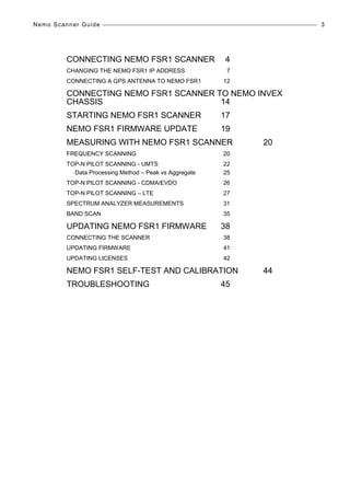
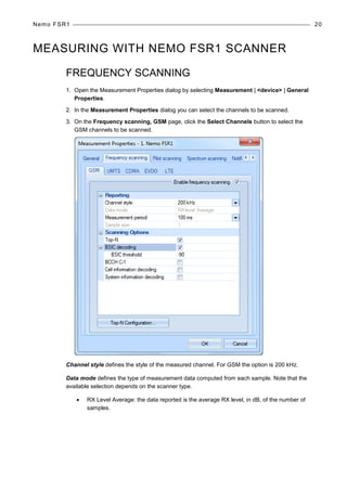
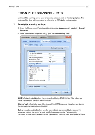

The document is a user manual for the Nemo FSR1 Scanner by Anite Finland Ltd, detailing installation, configuration, and operation procedures. It includes information on connecting the scanner, changing IP addresses, firmware updates, and troubleshooting, along with specific instructions for connecting to a GPS and the Nemo Invex chassis. Important operational notes, warnings, and technical specifications are also provided to assist users in effectively utilizing the scanner.


![Nemo outdoor 6_training_aug2011 [compatibility mode]](https://cdn.slidesharecdn.com/ss_thumbnails/nemooutdoor6trainingaug2011compatibilitymode-130826015745-phpapp02-thumbnail.jpg?width=640&height=640&fit=bounds)


