A GUEST LECTURE
on
COMPUTERNETWORKS
for
III YEAR B.TECH(CSE) – I SEM
BY
DR. K. KRANTHI KUMAR
Associate Professor, Dept of IT,
Sreenidhi Institute of science and technology, Hyderabad,
drkkranthikumar@gmail.com, 9848624931
JAWAHARLAL NEHRU TECHNOLOGICAL UNIVERSITY HYDERABAD
UNIVERSITY COLLEGE OF ENGINEERING RAJANNA SIRCILLA
Agraharam, Rajanna Sircilla District, Telangana State, India. Pin Code: 505302
2.
COMPUTER NETWORKS SYLLABUS
UNIT- I
Network hardware, Network software, OSI, TCP/IP Reference models, Example
Networks: ARPANET, Internet. Physical Layer: Guided Transmission media:
twisted pairs, coaxial cable, fiber optics, Wireless Transmission. Data link layer:
Design issues, framing, Error detection and correction.
UNIT - II
Elementary data link protocols: simplex protocol, A simplex stop and wait protocol
for an error-free channel, A simplex stop and wait protocol for noisy channel.
Sliding Window protocols: A one-bit sliding window protocol, A protocol using Go-
Back-N, A protocol using Selective Repeat, Example data link protocols.
Medium Access sub layer: The channel allocation problem, Multiple access
protocols: ALOHA, Carrier sense multiple access protocols, collision free
protocols. Wireless LANs, Data link layer switching.
3.
UNIT - III
NetworkLayer: Design issues, Routing algorithms: shortest path routing,
Flooding, Hierarchical routing, Broadcast, Multicast, distance vector
routing, Congestion Control Algorithms, Quality of Service,
Internetworking, The Network layer in the internet.
UNIT - IV
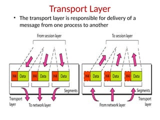
Transport Layer: Transport Services, Elements of Transport protocols,
Connection management, TCP and UDP protocols.
UNIT - V
Application Layer –Domain name system, SNMP, Electronic Mail; the
World WEB, HTTP, Streaming audio and video.
TEXT BOOK:
1. Computer Networks -- Andrew S Tanenbaum, David. j. Wetherall, 5th
Edition. Pearson Education/PHI .
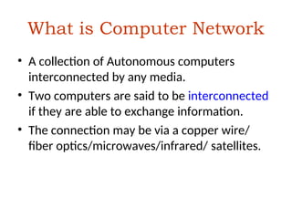
What is ComputerNetwork
• A collection of Autonomous computers
interconnected by any media.
• Two computers are said to be interconnected
if they are able to exchange information.
• The connection may be via a copper wire/
fiber optics/microwaves/infrared/ satellites.
6.
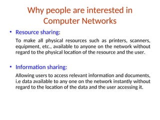
Why people areinterested in
Computer Networks
• Resource sharing:
To make all physical resources such as printers, scanners,
equipment, etc., available to anyone on the network without
regard to the physical location of the resource and the user.
• Information sharing:
Allowing users to access relevant information and documents,
i.e data available to any one on the network instantly without
regard to the location of the data and the user accessing it.
7.
Uses of ComputerNetworks
• Business Applications
• Home Applications
• Mobile Users
• Social Issues
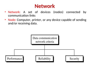
Network
• Network: Aset of devices (nodes) connected by
communication links
• Node: Computer, printer, or any device capable of sending
and/or receiving data.
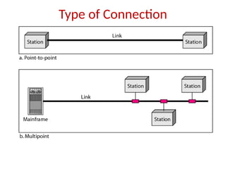
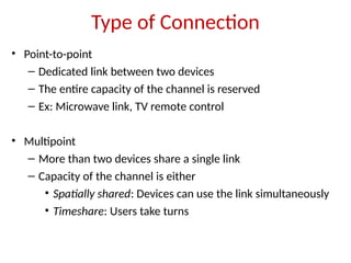
Type of Connection
•Point-to-point
– Dedicated link between two devices
– The entire capacity of the channel is reserved
– Ex: Microwave link, TV remote control
• Multipoint
– More than two devices share a single link
– Capacity of the channel is either
• Spatially shared: Devices can use the link simultaneously
• Timeshare: Users take turns
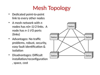
Mesh Topology
• Dedicatedpoint-to-point
link to every other nodes
• A mesh network with n
nodes has n(n-1)/2 links. A
node has n-1 I/O ports
(links)
• Advantages: No traffic
problems, robust, security,
easy fault identification &
isolation
• Disadvantages: Difficult
installation/reconfiguration
, space, cost
14.
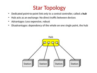
Star Topology
• Dedicatedpoint-to-point link only to a central controller, called a hub
• Hub acts as an exchange: No direct traffic between devices
• Advantages: Less expensive, robust
• Disadvantages: dependency of the whole on one single point, the hub
15.
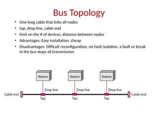
Bus Topology
• Onelong cable that links all nodes
• tap, drop line, cable end
• limit on the # of devices, distance between nodes
• Advantages: Easy installation, cheap
• Disadvantages: Difficult reconfiguration, no fault isolation, a fault or break
in the bus stops all transmission
16.
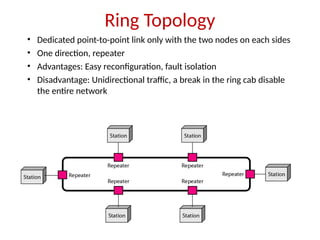
Ring Topology
• Dedicatedpoint-to-point link only with the two nodes on each sides
• One direction, repeater
• Advantages: Easy reconfiguration, fault isolation
• Disadvantage: Unidirectional traffic, a break in the ring cab disable
the entire network
17.
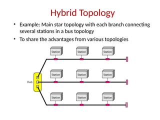
Hybrid Topology
• Example:Main star topology with each branch connecting
several stations in a bus topology
• To share the advantages from various topologies
18.
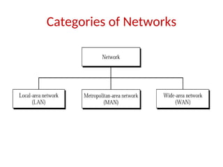
Types of Network
•Local Area Networks
• Metropolitan Area Networks
• Wide Area Networks
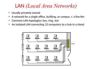
LAN (Local AreaNetworks)
• Usually privately owned
• A network for a single office, building, or campus a few Km
• Common LAN topologies: bus, ring, star
• An isolated LAN connecting 12 computers to a hub in a closet
22.
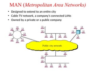
MAN (Metropolitan AreaNetworks)
• Designed to extend to an entire city
• Cable TV network, a company’s connected LANs
• Owned by a private or a public company
23.
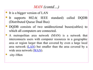
MAN (contd…)
Itis a bigger version of LAN
It supports 802.6( IEEE standard) called DQDB
(Distributed Queue Dual Bus)
DQDB consists of two unidirectional buses(cables) to
which all computers are connected.
A metropolitan area network (MAN) is a network that
interconnects users with computer resources in a geographic
area or region larger than that covered by even a large local
area network (LAN) but smaller than the area covered by a
wide area network (WAN).
city-10km
24.
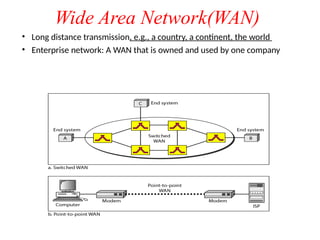
Wide Area Network(WAN)
•Long distance transmission, e.g., a country, a continent, the world
• Enterprise network: A WAN that is owned and used by one company
25.
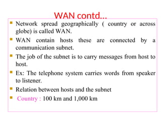
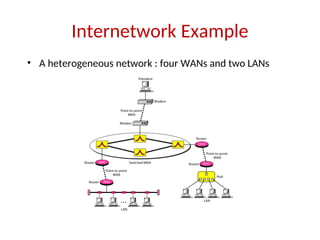
WAN contd…
Networkspread geographically ( country or across
globe) is called WAN.
WAN contain hosts these are connected by a
communication subnet.
The job of the subnet is to carry messages from host to
host.
Ex: The telephone system carries words from speaker
to listener.
Relation between hosts and the subnet
Country : 100 km and 1,000 km
26.
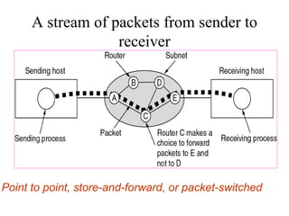
A stream ofpackets from sender to
receiver
Point to point, store-and-forward, or packet-switched
27.
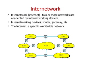
Internetwork
• Internetwork (internet): two or more networks are
connected by internetworking devices
• Internetworking devices: router, gateway, etc.
• The Internet: a specific worldwide network
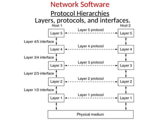
Network Software
• ProtocolHierarchies
• Design Issues for the Layers
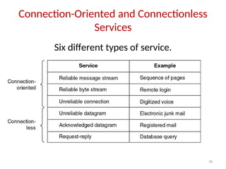
• Connection-Oriented and Connectionless Services
• Service Primitives
• The Relationship of Services to Protocols
29
30.
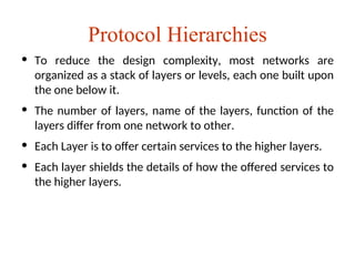
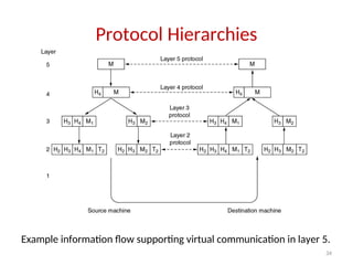
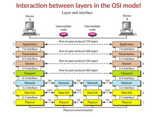
Protocol Hierarchies
• Toreduce the design complexity, most networks are
organized as a stack of layers or levels, each one built upon
the one below it.
• The number of layers, name of the layers, function of the
layers differ from one network to other.
• Each Layer is to offer certain services to the higher layers.
• Each layer shields the details of how the offered services to
the higher layers.
31.
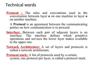
Technical words
Protocol :The rules and conventions used in the
conversation between layer n on one machine to layer n
on another machine.
A Protocol is an agreement between the communicating
parties on how communication is to proceed.
Interface: Between each pair of adjacent layers is an
interface. The interface defines which primitive
operations and services the lower layer makes available
to the upper one.
Network Architecture: A set of layers and protocols is
called a network architecture.
Protocol stack: A list of protocols used by a certain
system, one protocol per layer, is called a protocol stack.
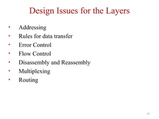
Design Issues forthe Layers
• Addressing
• Rules for data transfer
• Error Control
• Flow Control
• Disassembly and Reassembly
• Multiplexing
• Routing
35
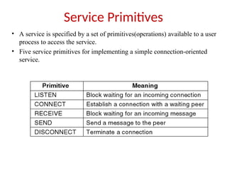
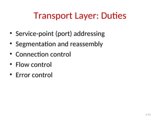
Service Primitives
• Aservice is specified by a set of primitives(operations) available to a user
process to access the service.
• Five service primitives for implementing a simple connection-oriented
service.
38.
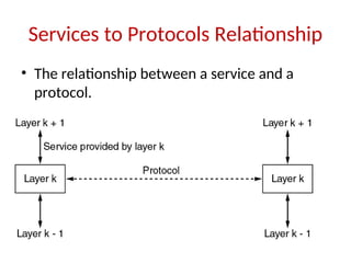
Services to ProtocolsRelationship
• The relationship between a service and a
protocol.
39.
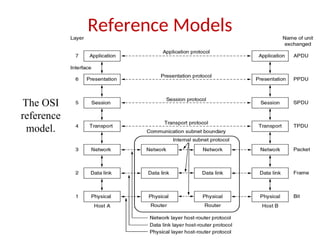
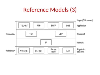
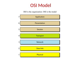
Reference Models
• TheOSI Reference Model
• The TCP/IP Reference Model
• A Comparison of OSI and TCP/IP
• A Critique of the OSI Model and Protocols
• A Critique of the TCP/IP Reference Model
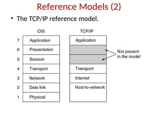
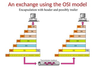
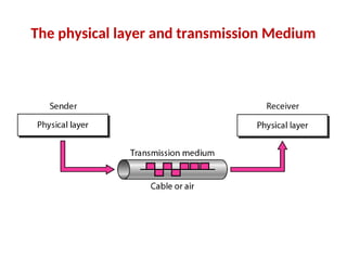
An exchange usingthe OSI model
Encapsulation with header and possibly trailer
46.
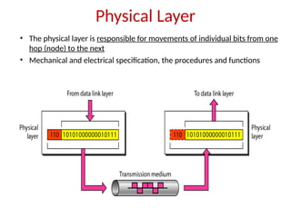
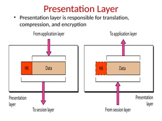
Physical Layer
• Thephysical layer is responsible for movements of individual bits from one
hop (node) to the next
• Mechanical and electrical specification, the procedures and functions
47.
2-47
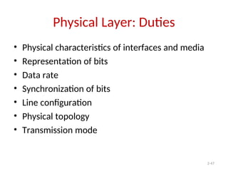
Physical Layer: Duties
•Physical characteristics of interfaces and media
• Representation of bits
• Data rate
• Synchronization of bits
• Line configuration
• Physical topology
• Transmission mode
48.
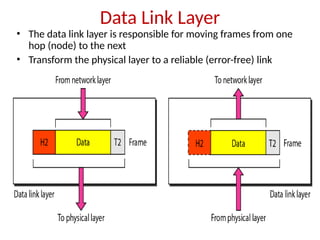
Data Link Layer
•The data link layer is responsible for moving frames from one
hop (node) to the next
• Transform the physical layer to a reliable (error-free) link
49.
2-49
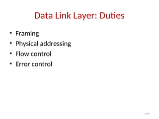
Data Link Layer:Duties
• Framing
• Physical addressing
• Flow control
• Error control
50.
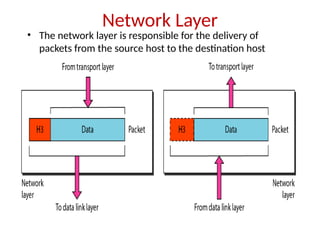
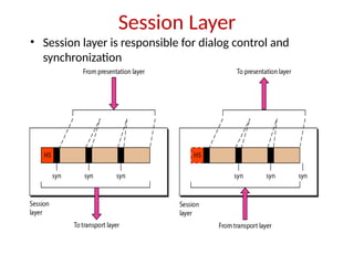
Network Layer
• Thenetwork layer is responsible for the delivery of
packets from the source host to the destination host
Application Layer: Services
•Network virtual terminal: It allows a user to
log on to a remote host.
• Mail services
• File transfer, access, and management
• Directory services: provides distributed
database sources and access for global
information about various objects and
services.
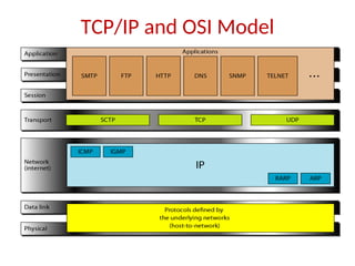
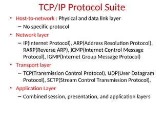
TCP/IP Protocol Suite
•Host-to-network : Physical and data link layer
– No specific protocol
• Network layer
– IP(Internet Protocol), ARP(Address Resolution Protocol),
RARP(Reverse ARP), ICMP(Internet Control Message
Protocol), IGMP(Internet Group Message Protocol)
• Transport layer
– TCP(Transmission Control Protocol), UDP(User Datagram
Protocol), SCTP(Stream Control Transmission Protocol),
• Application Layer
– Combined session, presentation, and application layers
61.
2-61
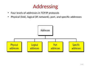
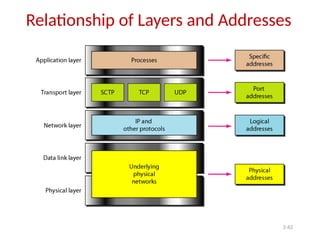
Addressing
• Four levelsof addresses in TCP/IP protocols
• Physical (link), logical (IP, network), port, and specific addresses
2-63
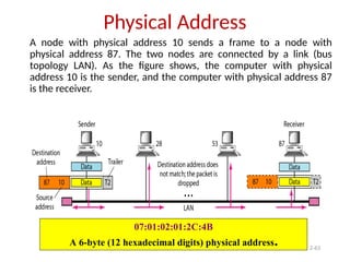
Physical Address
A nodewith physical address 10 sends a frame to a node with
physical address 87. The two nodes are connected by a link (bus
topology LAN). As the figure shows, the computer with physical
address 10 is the sender, and the computer with physical address 87
is the receiver.
07:01:02:01:2C:4B
A 6-byte (12 hexadecimal digits) physical address.
64.
2-64
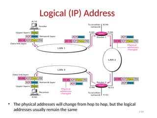
Logical (IP) Address
•The physical addresses will change from hop to hop, but the logical
addresses usually remain the same
65.
2-65
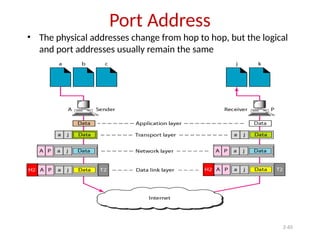
Port Address
• Thephysical addresses change from hop to hop, but the logical
and port addresses usually remain the same
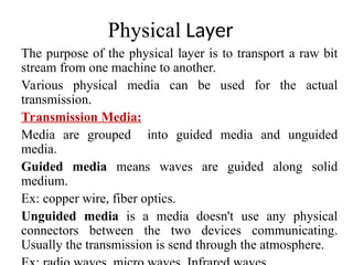
Physical Layer
The purposeof the physical layer is to transport a raw bit
stream from one machine to another.
Various physical media can be used for the actual
transmission.
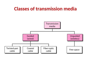
Transmission Media:
Media are grouped into guided media and unguided
media.
Guided media means waves are guided along solid
medium.
Ex: copper wire, fiber optics.
Unguided media is a media doesn't use any physical
connectors between the two devices communicating.
Usually the transmission is send through the atmosphere.
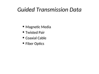
Magnetic Media
• Oneof the common way to transport data from
one computer to another is to write them on to
magnetic tape or removable media (DVD)
physically transport the tape or DVD to the
destination machine and read them.
• The tape densities are increasing.
• It is not suitable in applications, where on-line
connection is needed
72.
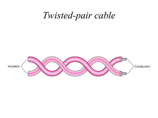
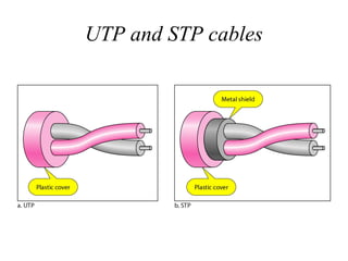
Twisted Pair
• Oldesttransmission media
• A twisted pair consists of two insulated copper wires typically
about 1mm thick. The wires are twisted together in a helical
form.
• Cheap medium
• Commonly used for communications within buildings and in
telephone networks
• For longer distance repeaters are needed.
• Twisted pairs can be used for transmitting either analog or
digital signals.
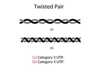
• Produced in unshielded (UTP) and shielded (STP) forms, and
in different performance categories.
• Category 5 has more twists per centimeter.
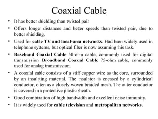
• It hasbetter shielding than twisted pair
• Offers longer distances and better speeds than twisted pair, due to
better shielding.
• Used for cable TV and local-area networks. Had been widely used in
telephone systems, but optical fiber is now assuming this task.
• Baseband Coaxial Cable 50-ohm cable, commonly used for digital
transmission. Broadband Coaxial Cable 75-ohm cable, commonly
used for analog transmission.
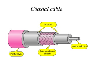
• A coaxial cable consists of a stiff copper wire as the core, surrounded
by an insulating material. The insulator is encased by a cylindrical
conductor, often as a closely woven braided mesh. The outer conductor
is covered in a protective plastic sheath.
• Good combination of high bandwidth and excellent noise immunity.
• It is widely used for cable television and metropolitan networks.
Coaxial Cable
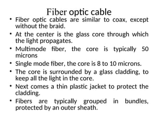
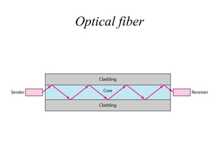
Fiber optic cable
•Fiber optic cables are similar to coax, except
without the braid.
• At the center is the glass core through which
the light propagates.
• Multimode fiber, the core is typically 50
microns
• Single mode fiber, the core is 8 to 10 microns.
• The core is surrounded by a glass cladding, to
keep all the light in the core.
• Next comes a thin plastic jacket to protect the
cladding.
• Fibers are typically grouped in bundles,
protected by an outer sheath.
80.
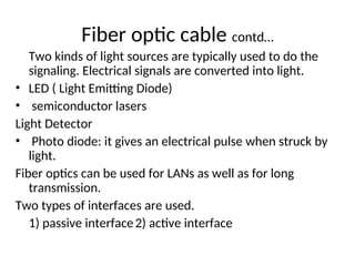
Two kinds oflight sources are typically used to do the
signaling. Electrical signals are converted into light.
• LED ( Light Emitting Diode)
• semiconductor lasers
Light Detector
• Photo diode: it gives an electrical pulse when struck by
light.
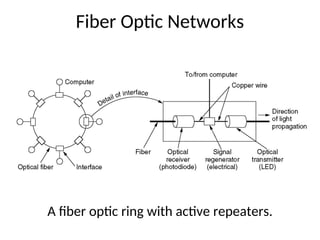
Fiber optics can be used for LANs as well as for long
transmission.
Two types of interfaces are used.
1) passive interface2) active interface
Fiber optic cable contd…
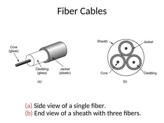
Fiber Cables
(a) Sideview of a single fiber.
(b) End view of a sheath with three fibers.
83.
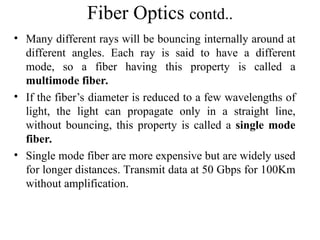
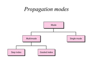
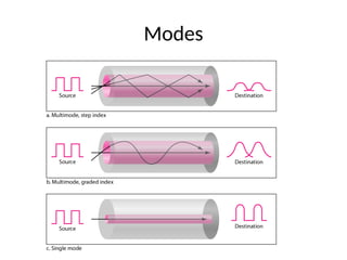
Fiber Optics contd..
•Many different rays will be bouncing internally around at
different angles. Each ray is said to have a different
mode, so a fiber having this property is called a
multimode fiber.
• If the fiber’s diameter is reduced to a few wavelengths of
light, the light can propagate only in a straight line,
without bouncing, this property is called a single mode
fiber.
• Single mode fiber are more expensive but are widely used
for longer distances. Transmit data at 50 Gbps for 100Km
without amplification.
Wireless transmission
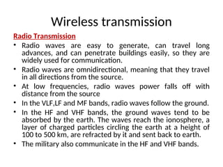
Radio Transmission
•Radio waves are easy to generate, can travel long
advances, and can penetrate buildings easily, so they are
widely used for communication.
• Radio waves are omnidirectional, meaning that they travel
in all directions from the source.
• At low frequencies, radio waves power falls off with
distance from the source
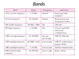
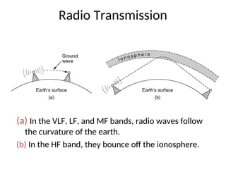
• In the VLF,LF and MF bands, radio waves follow the ground.
• In the HF and VHF bands, the ground waves tend to be
absorbed by the earth. The waves reach the ionosphere, a
layer of charged particles circling the earth at a height of
100 to 500 km, are refracted by it and sent back to earth.
• The military also communicate in the HF and VHF bands.
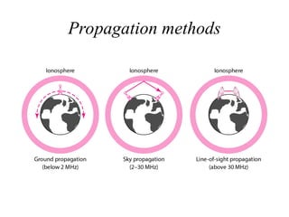
Radio Transmission
(a) Inthe VLF, LF, and MF bands, radio waves follow
the curvature of the earth.
(b) In the HF band, they bounce off the ionosphere.
93.
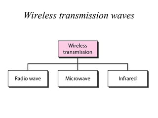
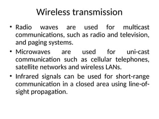
Wireless transmission
• Radiowaves are used for multicast
communications, such as radio and television,
and paging systems.
• Microwaves are used for uni-cast
communication such as cellular telephones,
satellite networks and wireless LANs.
• Infrared signals can be used for short-range
communication in a closed area using line-of-
sight propagation.
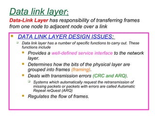
Data link layer:
DATA LINK LAYER DESIGN ISSUES:
Data link layer has a number of specific functions to carry out. These
functions include
Provides a well-defined service interface to the network
layer.
Determines how the bits of the physical layer are
grouped into frames (framing).
Deals with transmission errors (CRC and ARQ).
Systems which automatically request the retransmission of
missing packets or packets with errors are called Automatic
Repeat reQuest (ARQ)
Regulates the flow of frames.
Data-Link Layer has responsibility of transferring frames
from one node to adjacent node over a link
96.
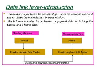
Data link layer-Introduction
The data link layer takes the packets it gets from the network layer and
encapsulates them into frames for transmission .
Each frame contains frame header ,a payload field for holding the
packet ,and a frame trailer
packet
Header payload field Trailer
packet
Header payload field Trailer
Relationship between packets and frames
Sending Machine Receiving Machine
97.
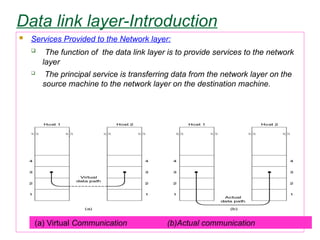
Data link layer-Introduction
Services Provided to the Network layer:
The function of the data link layer is to provide services to the network
layer
The principal service is transferring data from the network layer on the
source machine to the network layer on the destination machine.
(a) Virtual Communication (b)Actual communication
98.
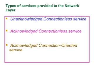
Types of servicesprovided to the Network
Layer
Unacknowledged Connectionless service
Acknowledged Connectionless service
Acknowledged Connection-Oriented
service
99.
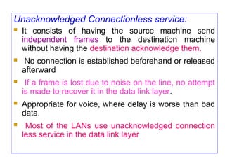
Unacknowledged Connectionless service:
It consists of having the source machine send
independent frames to the destination machine
without having the destination acknowledge them.
No connection is established beforehand or released
afterward
If a frame is lost due to noise on the line, no attempt
is made to recover it in the data link layer.
Appropriate for voice, where delay is worse than bad
data.
Most of the LANs use unacknowledged connection
less service in the data link layer
100.
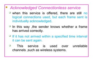
Acknowledged Connectionlessservice
when this service is offered, there are still no
logical connections used, but each frame sent is
individually acknowledged.
In this way ,the sender knows whether a frame
has arrived correctly.
If it has not arrived within a specified time interval
it can be sent again.
This service is used over unreliable
channels ,such as wireless systems.
101.
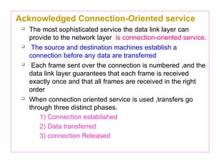
Acknowledged Connection-Oriented service
The most sophisticated service the data link layer can
provide to the network layer is connection-oriented service.
The source and destination machines establish a
connection before any data are transferred
Each frame sent over the connection is numbered ,and the
data link layer guarantees that each frame is received
exactly once and that all frames are received in the right
order
When connection oriented service is used ,transfers go
through three distinct phases.
1) Connection established
2) Data transferred
3) connection Released
102.
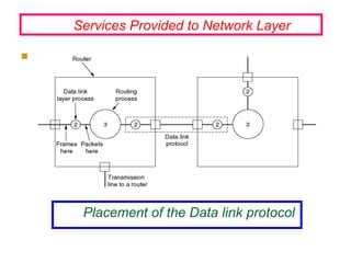
Placement of theData link protocol
Services Provided to Network Layer
103.
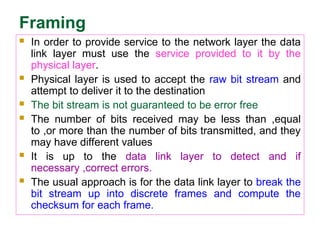
Framing
In orderto provide service to the network layer the data
link layer must use the service provided to it by the
physical layer.
Physical layer is used to accept the raw bit stream and
attempt to deliver it to the destination
The bit stream is not guaranteed to be error free
The number of bits received may be less than ,equal
to ,or more than the number of bits transmitted, and they
may have different values
It is up to the data link layer to detect and if
necessary ,correct errors.
The usual approach is for the data link layer to break the
bit stream up into discrete frames and compute the
checksum for each frame.
104.
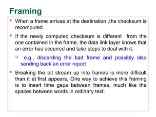
Framing
When aframe arrives at the destination ,the checksum is
recomputed.
If the newly computed checksum is different from the
one contained in the frame, the data link layer knows that
an error has occurred and take steps to deal with it.
e.g., discarding the bad frame and possibly also
sending back an error report
Breaking the bit stream up into frames is more difficult
than it at first appears, One way to achieve this framing
is to insert time gaps between frames, much like the
spaces between words in ordinary text.
105.
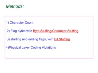
Methods:
1) Character Count
2)Flag bytes with Byte Stuffing/Character Stuffing
3) starting and ending flags, with Bit Stuffing
4)Physical Layer Coding Violations
106.
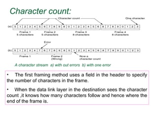
Character count:
• Thefirst framing method uses a field in the header to specify
the number of characters in the frame.
• When the data link layer in the destination sees the character
count ,it knows how many characters follow and hence where the
end of the frame is.
A character stream a) with out errors b) with one error
107.
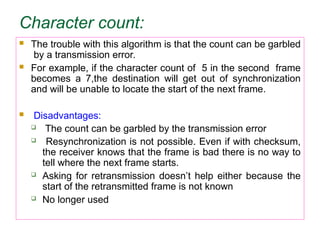
Character count:
Thetrouble with this algorithm is that the count can be garbled
by a transmission error.
For example, if the character count of 5 in the second frame
becomes a 7,the destination will get out of synchronization
and will be unable to locate the start of the next frame.
Disadvantages:
The count can be garbled by the transmission error
Resynchronization is not possible. Even if with checksum,
the receiver knows that the frame is bad there is no way to
tell where the next frame starts.
Asking for retransmission doesn’t help either because the
start of the retransmitted frame is not known
No longer used
108.
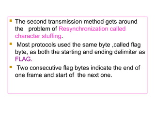
The secondtransmission method gets around
the problem of Resynchronization called
character stuffing.
Most protocols used the same byte ,called flag
byte, as both the starting and ending delimiter as
FLAG.
Two consecutive flag bytes indicate the end of
one frame and start of the next one.
109.
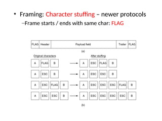
• Framing: Characterstuffing – newer protocols
–Frame starts / ends with same char: FLAG
110.
Byte Stuffing
[HDLC Example]
•Also referred to as character stuffing.
• ASCII characters are used as framing delimiters
(e.g. DLE STX and DLE ETX)
• The problem occurs when these character
patterns occur within the “transparent” data.
Solution: sender stuffs an extra DLE into the data
stream just before each occurrence of an
“accidental” DLE in the data stream.
The data link layer on the receiving end unstuffs the
DLE before giving the data to the network layer.
111.
DLE STX DLEETX
Transparent Data
DLE STX DLE ETX
A B DLE H W
DLE STX DLE ETX
A B DLE H W
DLE
DLE STX DLE ETX
A B DLE H W
Stuffed
Unstuffed
Before
Byte Stuffing
[HDLC Example]
112.
Computer Networks: Bitand Byte Stuffing 112
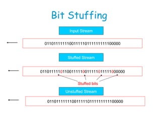
Bit Stuffing
• Each frame begins and ends with a special bit
pattern called a flag byte [01111110]. {Note this is
7E in hex}
• Whenever sender data link layer encounters five
consecutive ones in the data stream, it
automatically stuffs a 0 bit into the outgoing
stream.
• When the receiver sees five consecutive incoming
ones followed by a 0 bit, it automatically destuffs
the 0 bit before sending the data to the network
layer.
113.
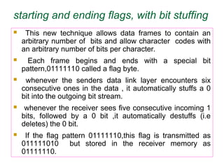
starting and endingflags, with bit stuffing
This new technique allows data frames to contain an
arbitrary number of bits and allow character codes with
an arbitrary number of bits per character.
Each frame begins and ends with a special bit
pattern,01111110 called a flag byte.
whenever the senders data link layer encounters six
consecutive ones in the data , it automatically stuffs a 0
bit into the outgoing bit stream.
whenever the receiver sees five consecutive incoming 1
bits, followed by a 0 bit ,it automatically destuffs (i.e
deletes) the 0 bit.
If the flag pattern 01111110,this flag is transmitted as
011111010 but stored in the receiver memory as
01111110.
114.
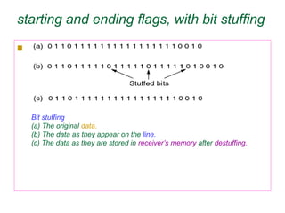
starting and endingflags, with bit stuffing
Bit stuffing
(a) The original data.
(b) The data as they appear on the line.
(c) The data as they are stored in receiver’s memory after destuffing.
Flag flag
Address ControlInformation CRC
Protocol
01111110 01111110
1111111 00000011
Unnumbered
frame
Specifies what kind of packet is contained in
the payload, e.g., LCP, NCP, IP, OSI
CLNP, IPX
All stations are to
accept the frame
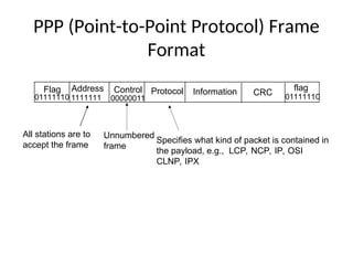
PPP (Point-to-Point Protocol) Frame
Format
117.
117
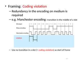
• Framing: Codingviolation
– Redundancy in the encoding on medium is
required
– e.g. Manchester encoding: transition in the middle of a slot
– Use no transition in a slot (= coding violation) as start of frame
violation
118.
Error Control:
Nextproblem: How to make sure all frames are
eventually delivered to the network layer at the
destination, and in the proper order.
The usual way to ensure reliable delivery is to provide
the sender with some feedback about what is happening
at the other end of the line.
The protocol calls for the receiver to send back special
control frames bearing positive and negative
acknowledgements about the incoming frames
119.
Error Control
Ifthe sender receives a positive acknowledgement about
a frame ,it knows the frame has arrived safely.
on the other hand, a negative acknowledgement means
that something has gone wrong, and the frame must be
transmitted again.
An additional complication comes from hardware
troubles.
Managing the Timers and sequence numbers so as to
ensure that each frame is ultimately passed to the network
layer at the destination exactly once.
120.
Error Control:
MaintainingTimers for Error Control: When a sender
transmits a frame, it generally also starts a timer .
The timer is set to expire after an interval long enough for
the frame to reach the destination, be processed there ,and
have the acknowledgement to propagate back to the sender.
Normally, the frame will be correctly received and the
acknowledgement will get back before the timer runs out ,in
which case the timer will be cancelled.
However, if either the frame or the acknowledgement is
lost ,the timer will go off ,alerting the sender to a potential
problem .the obvious solution is to just transmit the frame
again.
Sequence number is used to recognize the duplicate packet.
121.
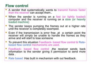
Flow control
Asender that systematically wants to transmit frames faster
than the receiver can accept them..
When the sender is running on a fast (or lightly loaded)
computer and the receiver is running on a slow (or heavily
loaded machine)
The sender keeps pumping the frames out at a higher rate
until the receiver is completely swamped.
Even if the transmission is error free ,at a certain point the
receiver will simply be unable to handle the frames as they
arrive and will start to lose someone
To prevent this situation Feedback- based flow control & Rate-
based flow control mechanisms are used.
Feedback- based flow control ,the receiver sends back
information to the sender giving it permission to send more
data .
Rate based :Has built in mechanism with out feedback.
122.
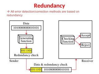
Error Detection andcorrection
In some cases it is sufficient to detect an error and in
some, it requires the errors to be corrected also.
For e.g.
On a reliable medium : Error Detection is sufficient
where the error rate is low and asking for
retransmission after Error Detection would work
efficiently
In contrast, on an unreliable medium : Retransmission
after Error Detection may result in another error and
still another and so on. Hence Error Correction is
desirable.
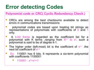
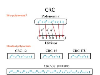
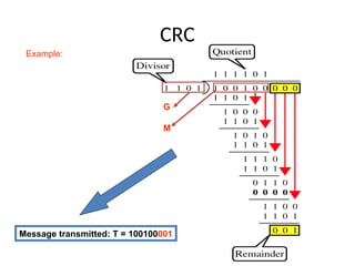
Error detecting Codes
Polynomialcode or CRC( Cyclic Redundancy Check )
CRCs are among the best checksums available to detect
errors in communications transmissions
polynomial codes are based upon treating bit strings as
representations of polynomials with coefficients of 0 and 1
only.
A k-bit frame is regarded as the coefficient list for a
polynomial with K terms ,ranging from Xk-1
to x0
. such a
polynomial is said to be of degree k-1.
The higher order (left-most) bit is the coefficient of xk-1
.the
next bit coefficient of xk-2
Ex: 110001 has 6 bits. It represents a six-term polynomial
with coefficients 1100001
110001 : x5
+x4
+1
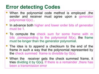
Error detecting Codes
When the polynomial code method is employed ,the
sender and receiver must agree upon a generator
polynomial G(x) .
In advance both higher and lower order bits of generator
must be 1.
To compute the check sum for some frame with m
bits ,corresponding to the polynomial M(x), the frame
must be longer than the generator polynomial.
The idea is to append a checksum to the end of the
frame in such a way that the polynomial represented by
the check summed frame is divisible by G(x).
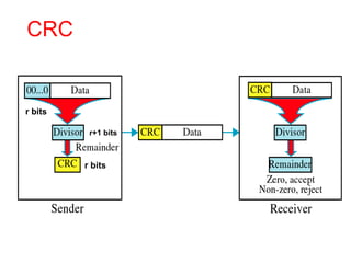
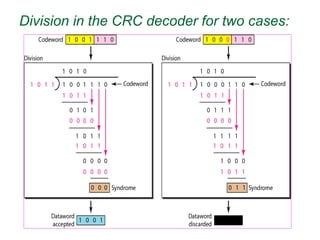
When the receiver gets the check summed frame, it
tries dividing it by G(x). If there is a remainder ,there has
been a transmission error
130.
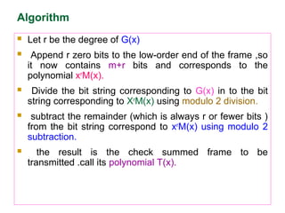
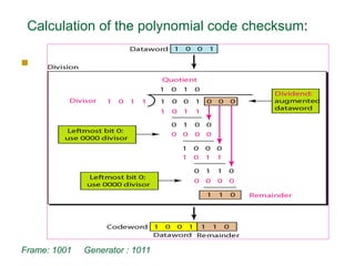
Algorithm
Let rbe the degree of G(x)
Append r zero bits to the low-order end of the frame ,so
it now contains m+r bits and corresponds to the
polynomial xr
M(x).
Divide the bit string corresponding to G(x) in to the bit
string corresponding to Xr
M(x) using modulo 2 division.
subtract the remainder (which is always r or fewer bits )
from the bit string correspond to xr
M(x) using modulo 2
subtraction.
the result is the check summed frame to be
transmitted .call its polynomial T(x).
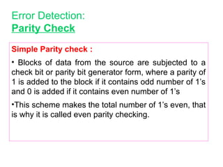
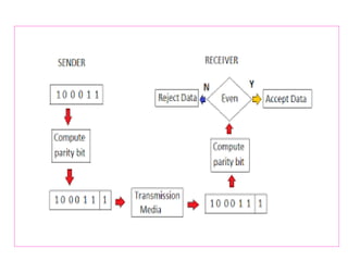
Error Detection:
Parity Check
SimpleParity check :
• Blocks of data from the source are subjected to a
check bit or parity bit generator form, where a parity of
1 is added to the block if it contains odd number of 1’s
and 0 is added if it contains even number of 1’s
•This scheme makes the total number of 1’s even, that
is why it is called even parity checking.
136.
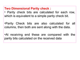
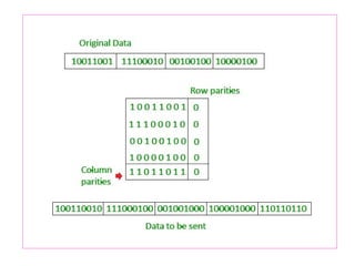
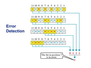
Two Dimensional Paritycheck :
• Parity check bits are calculated for each row,
which is equivalent to a simple parity check bit.
•Parity Check bits are also calculated for all
columns, then both are sent along with the data.
•At receiving end these are compared with the
parity bits calculated on the received data
138.
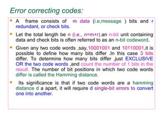
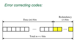
Error correcting codes:
A frame consists of m data (i.e,message ) bits and r
redundant, or check bits.
Let the total length be n (i.e., n=m+r).an n-bit unit containing
data and check bits is often referred to as an n-bit codeword.
Given any two code words ,say,10001001 and 10110001,it is
possible to define how many bits differ .In this case 3 bits
differ. To determine how many bits differ ,just EXCLUSIVE
OR the two code words ,and count the number of 1 bits in the
result. The number of bit positions in which two code words
differ is called the Hamming distance.
Its significance is that if two code words are a hamming
distance d a apart, it will require d single-bit errors to convert
one into another.
139.
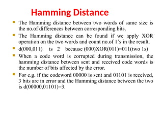
Hamming Distance
TheHamming distance between two words of same size is
the no.of differences between corresponding bits.
The Hamming distance can be found if we apply XOR
operation on the two words and count no.of 1’s in the result.
d(000,011) is 2 because (000)XOR(011)=011(two 1s)
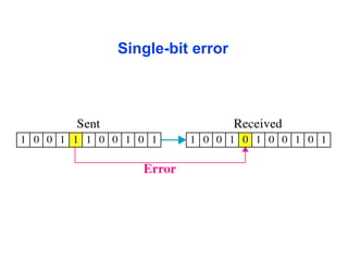
When a code word is corrupted during transmission, the
hamming distance between sent and received code words is
the number of bits affected by the error.
For e.g. if the codeword 00000 is sent and 01101 is received,
3 bits are in error and the Hamming distance between the two
is d(00000,01101)=3.
140.
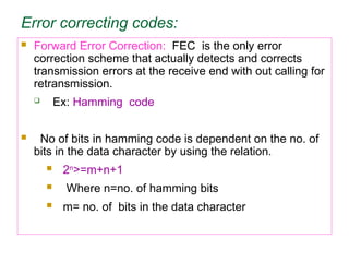
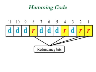
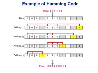
Error correcting codes:
Forward Error Correction: FEC is the only error
correction scheme that actually detects and corrects
transmission errors at the receive end with out calling for
retransmission.
Ex: Hamming code
No of bits in hamming code is dependent on the no. of
bits in the data character by using the relation.
2n
>=m+n+1
Where n=no. of hamming bits
m= no. of bits in the data character
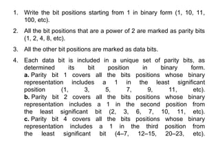
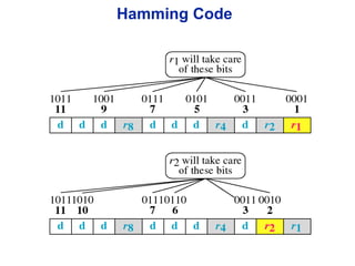
1. Write thebit positions starting from 1 in binary form (1, 10, 11,
100, etc).
2. All the bit positions that are a power of 2 are marked as parity bits
(1, 2, 4, 8, etc).
3. All the other bit positions are marked as data bits.
4. Each data bit is included in a unique set of parity bits, as
determined its bit position in binary form.
a. Parity bit 1 covers all the bits positions whose binary
representation includes a 1 in the least significant
position (1, 3, 5, 7, 9, 11, etc).
b. Parity bit 2 covers all the bits positions whose binary
representation includes a 1 in the second position from
the least significant bit (2, 3, 6, 7, 10, 11, etc).
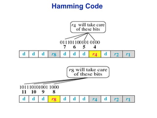
c. Parity bit 4 covers all the bits positions whose binary
representation includes a 1 in the third position from
the least significant bit (4–7, 12–15, 20–23, etc).
143.
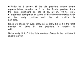
d. Parity bit8 covers all the bits positions whose binary
representation includes a 1 in the fourth position from
the least significant bit bits (8–15, 24–31, 40–47, etc).
e. In general each parity bit covers all bits where the bitwise AND
of the parity position and the bit position is
non-zero.
Since we check for even parity set a parity bit to 1 if the total
number of ones in the positions it checks is
odd.
Set a parity bit to 0 if the total number of ones in the positions it
checks is even
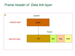
Frame header ofData link layer
ack seq kind
info
buffer
frame
packet
network layer
data link layer
151.
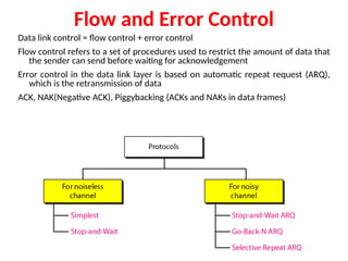
Flow and ErrorControl
Data link control = flow control + error control
Flow control refers to a set of procedures used to restrict the amount of data that
the sender can send before waiting for acknowledgement
Error control in the data link layer is based on automatic repeat request (ARQ),
which is the retransmission of data
ACK, NAK(Negative ACK), Piggybacking (ACKs and NAKs in data frames)
152.
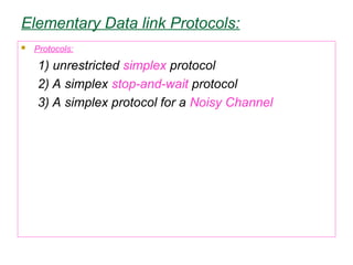
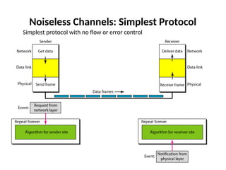
Elementary Data linkProtocols:
Protocols:
1) unrestricted simplex protocol
2) A simplex stop-and-wait protocol
3) A simplex protocol for a Noisy Channel
153.
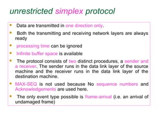
unrestricted simplex protocol
Data are transmitted in one direction only.
Both the transmitting and receiving network layers are always
ready
processing time can be ignored
Infinite buffer space is available
The protocol consists of two distinct procedures, a sender and
a receiver. The sender runs in the data link layer of the source
machine and the receiver runs in the data link layer of the
destination machine.
MAX-SEQ is not used because No sequence numbers and
Acknowledgements are used here.
The only event type possible is frame-arrival (i.e. an arrival of
undamaged frame)
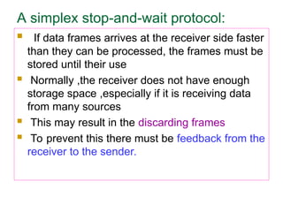
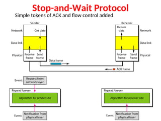
A simplex stop-and-waitprotocol:
If data frames arrives at the receiver side faster
than they can be processed, the frames must be
stored until their use
Normally ,the receiver does not have enough
storage space ,especially if it is receiving data
from many sources
This may result in the discarding frames
To prevent this there must be feedback from the
receiver to the sender.
157.
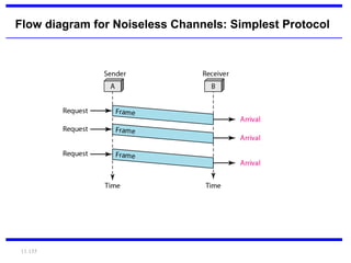
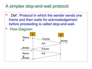
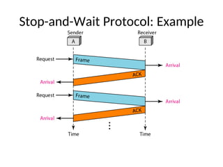
A simplex stop-and-waitprotocol:
Def : Protocol in which the sender sends one
frame and then waits for acknowledgement
before proceeding is called stop-and-wait.
Flow Diagram:
B
A
Reque
st
Frame
Ack
Frame
Ack
Arrival
Reque
st
Arrival
Arrival
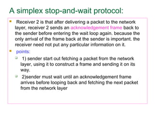
A simplex stop-and-waitprotocol:
Receiver 2 is that after delivering a packet to the network
layer, receiver 2 sends an acknowledgement frame back to
the sender before entering the wait loop again. because the
only arrival of the frame back at the sender is important. the
receiver need not put any particular information on it.
points:
1) sender start out fetching a packet from the network
layer, using it to construct a frame and sending it on its
way.
2)sender must wait until an acknowledgement frame
arrives before looping back and fetching the next packet
from the network layer
161.
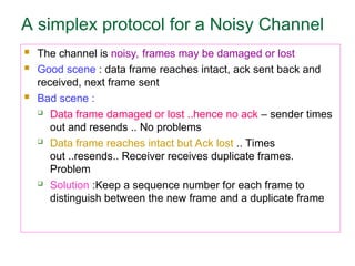
A simplex protocolfor a Noisy Channel
The channel is noisy, frames may be damaged or lost
Good scene : data frame reaches intact, ack sent back and
received, next frame sent
Bad scene :
Data frame damaged or lost ..hence no ack – sender times
out and resends .. No problems
Data frame reaches intact but Ack lost .. Times
out ..resends.. Receiver receives duplicate frames.
Problem
Solution :Keep a sequence number for each frame to
distinguish between the new frame and a duplicate frame
162.
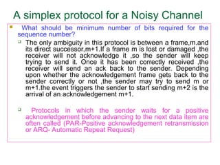
A simplex protocolfor a Noisy Channel
What should be minimum number of bits required for the
sequence number?
The only ambiguity in this protocol is between a frame,m.and
its direct successor,m+1.If a frame m is lost or damaged ,the
receiver will not acknowledge it ,so the sender will keep
trying to send it. Once it has been correctly received ,the
receiver will send an ack back to the sender. Depending
upon whether the acknowledgement frame gets back to the
sender correctly or not ,the sender may try to send m or
m+1.the event triggers the sender to start sending m+2 is the
arrival of an acknowledgement m+1.
Protocols in which the sender waits for a positive
acknowledgement before advancing to the next data item are
often called (PAR-Positive acknowledgement retransmission
or ARQ- Automatic Repeat Request)
163.
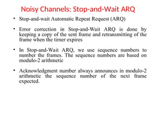
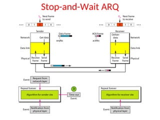
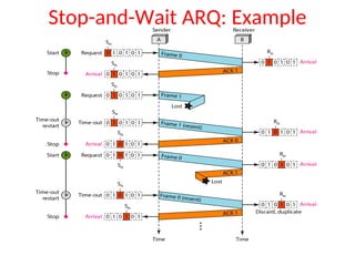
Noisy Channels: Stop-and-WaitARQ
• Stop-and-wait Automatic Repeat Request (ARQ)
• Error correction in Stop-and-Wait ARQ is done by
keeping a copy of the sent frame and retransmitting of the
frame when the timer expires
• In Stop-and-Wait ARQ, we use sequence numbers to
number the frames. The sequence numbers are based on
modulo-2 arithmetic
• Acknowledgment number always announces in modulo-2
arithmetic the sequence number of the next frame
expected.
Contd..
• The Stop-and-WaitARQ is very inefficient if
our channel has a large bandwidth and long
round-trip delay.
• There is no Pipelining in this protocol because
we need to wait for a frame to reach the
destination and be acknowledged before the
next frame is sent.
167.
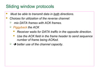
Sliding window protocols
Must be able to transmit data in both directions.
Choices for utilization of the reverse channel:
mix DATA frames with ACK frames.
Piggyback the ACK
Receiver waits for DATA traffic in the opposite direction.
Use the ACK field in the frame header to send sequence
number of frame being ACKed.
better use of the channel capacity.
168.
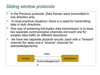
Sliding window protocols:
In the Previous protocols ,Data frames were transmitted in
one direction only.
In most practical situations ,there is a need for transmitting
data in both directions.
One way of achieving full-duplex data transmission is to have
two separate communication channels and each one for
simplex data traffic (in different directions)
we have two separate physical circuits ,each with a “forward”
channel (for data) and a “reverse” channel( for
acknowledgements).
source Destination
Data
Acknowledgement
s
169.
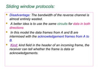
Sliding window protocols:
Disadvantage: The bandwidth of the reverse channel is
almost entirely wasted.
A better idea is to use the same circuits for data in both
directions
In this model the data frames from A and B are
intermixed with the acknowledgement frames from A to
B.
Kind: kind field in the header of an incoming frame, the
receiver can tell whether the frame is data or
acknowledgements.
170.
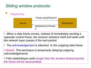
Sliding window protocols:
Piggybacking:
source Destination
Frame sent(Frame1)
Ack(frame1)+Frame
2
• When a data frame arrives, instead of immediately sending a
separate control frame, the receiver restrains itself and waits until
the network layer passes it the next packet.
• The acknowledgement is attached to the outgoing data frame
• Disadv: This technique is temporarily delaying outgoing
acknowledgements.
• If the datalinklayer waits longer than the senders timeout period,
the frame will be retransmitted.
171.
Sliding window protocols:
Rule: sender waiting a fixed number of milliseconds. If a new
packet arrives quickly the acknowledgement is piggybacked
onto it. other wise if no new packet has arrived by the end of
this time period ,the data link layer just sends a separate
acknowledgement frame.
In sliding window protocol each frame contains a sequence
number ranging from 0 up to some maximum.
The maximum is usually 2n
-1 so the sequence number fits
nicely in an n-bit field.
The stop-and-wait sliding window protocol uses n=1
restricting the sequence numbers 0 and 1.
The sender must keep all these frames in its memory for
possible retransmission
172.
Sliding window protocols:
Thus if the maximum window size is n, the sender needs n
buffers to hold the unacknowledged frames
3 bit field -000
001
010..etc
here n=3 i.e. 23
-1=7
window size is 0 to 7
Sliding window :: sender has a window of frames and maintains a list
of consecutive sequence numbers for frames that it is permitted to
send without waiting for ACKs.
receiver has a window that is a list of frame sequence numbers it is
permitted to accept.
Note – sending and receiving windows do NOT have to be the same
size.
173.
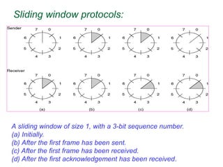
Sliding window protocols:
Asliding window of size 1, with a 3-bit sequence number.
(a) Initially.
(b) After the first frame has been sent.
(c) After the first frame has been received.
(d) After the first acknowledgement has been received.
174.
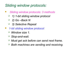
Sliding window protocols:
Sliding window protocols: 3 methods
1) 1-bit sliding window protocol
2) Go –Back N
3) Selective Repeat
1-bit sliding window protocol:
Window size 1.
Stop-and-wait.
Must get ack before can send next frame.
Both machines are sending and receiving.
175.
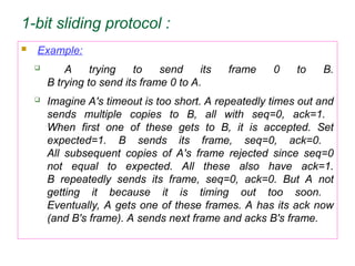
1-bit sliding protocol:
Example:
A trying to send its frame 0 to B.
B trying to send its frame 0 to A.
Imagine A's timeout is too short. A repeatedly times out and
sends multiple copies to B, all with seq=0, ack=1.
When first one of these gets to B, it is accepted. Set
expected=1. B sends its frame, seq=0, ack=0.
All subsequent copies of A's frame rejected since seq=0
not equal to expected. All these also have ack=1.
B repeatedly sends its frame, seq=0, ack=0. But A not
getting it because it is timing out too soon.
Eventually, A gets one of these frames. A has its ack now
(and B's frame). A sends next frame and acks B's frame.
176.
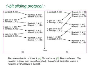
1-bit sliding protocol:
Two scenarios for protocol 4. (a) Normal case. (b) Abnormal case. The
notation is (seq, ack, packet number). An asterisk indicates where a
network layer accepts a packet.
177.
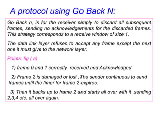
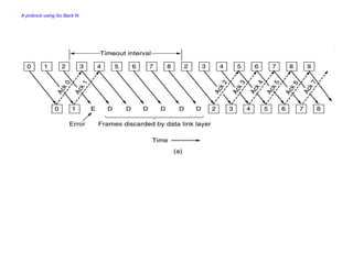
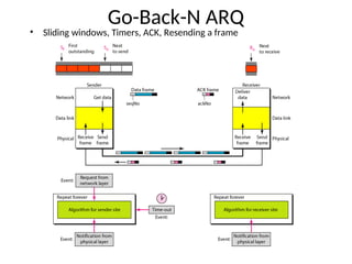
A protocol usingGo Back N:
Go Back n, is for the receiver simply to discard all subsequent
frames, sending no acknowledgements for the discarded frames.
This strategy corresponds to a receive window of size 1.
The data link layer refuses to accept any frame except the next
one it must give to the network layer.
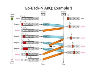
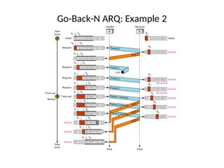
Points: fig ( a)
1) frame 0 and 1 correctly received and Acknowledged
2) Frame 2 is damaged or lost ,The sender continuous to send
frames until the timer for frame 2 expires.
3) Then it backs up to frame 2 and starts all over with it ,sending
2,3,4 etc. all over again.
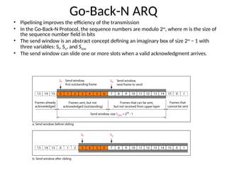
Go-Back-N ARQ
• Pipeliningimproves the efficiency of the transmission
• In the Go-Back-N Protocol, the sequence numbers are modulo 2m
, where m is the size of
the sequence number field in bits
• The send window is an abstract concept defining an imaginary box of size 2m
− 1 with
three variables: Sf, Sn, and Ssize
• The send window can slide one or more slots when a valid acknowledgment arrives.
180.
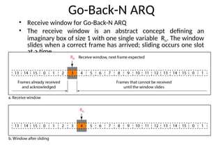
Go-Back-N ARQ
• Receivewindow for Go-Back-N ARQ
• The receive window is an abstract concept defining an
imaginary box of size 1 with one single variable Rn. The window
slides when a correct frame has arrived; sliding occurs one slot
at a time.
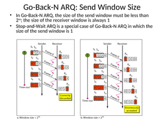
Go-Back-N ARQ: SendWindow Size
• In Go-Back-N ARQ, the size of the send window must be less than
2m
; the size of the receiver window is always 1
• Stop-and-Wait ARQ is a special case of Go-Back-N ARQ in which the
size of the send window is 1
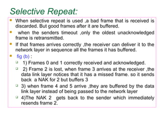
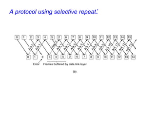
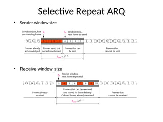
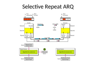
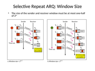
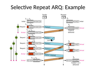
Selective Repeat:
Whenselective repeat is used ,a bad frame that is received is
discarded. But good frames after it are buffered.
when the senders timeout ,only the oldest unacknowledged
frame is retransmitted.
If that frames arrives correctly ,the receiver can deliver it to the
network layer in sequence all the frames it has buffered.
fig (b) :
1) Frames 0 and 1 correctly received and acknowledged.
2) Frame 2 is lost, when frame 3 arrives at the receiver ,the
data link layer notices that it has a missed frame. so it sends
back a NAK for 2 but buffers 3
3) when frame 4 and 5 arrive ,they are buffered by the data
link layer instead of being passed to the network layer
4)The NAK 2 gets back to the sender which immediately
resends frame 2.
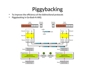
Piggybacking
• To improvethe efficiency of the bidirectional protocols
• Piggybacking in Go-Back-N ARQ
192.
Example Data LinkProtocols:
The Data Link Layer in the Internet - LANs use broadcast
protocols (Ethernet) to connect many hosts but
interconnection of LANs into larger networks is primary
done through routers running a point-to-point protocol. In
the case of the Internet, point-to-point protocol is also used
to connect host to router in the form of an Internet Service
Provider. Two point-to-point protocols widely used on the
Internet are SLIP and PPP.
SLIP – Serial Line Internet Protocol- Designed to connect
hosts to the internet over serial communications.
193.
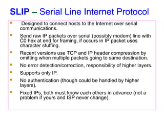
SLIP – SerialLine Internet Protocol
Designed to connect hosts to the Internet over serial
communications.
Send raw IP packets over serial (possibly modem) line with
C0 hex at end for framing, if occurs in IP packet uses
character stuffing.
Recent versions use TCP and IP header compression by
omitting when multiple packets going to same destination.
No error detection/correction, responsibility of higher layers.
Supports only IP.
No authentication (though could be handled by higher
layers).
Fixed IPs, both must know each others in advance (not a
problem if yours and ISP never change).
194.
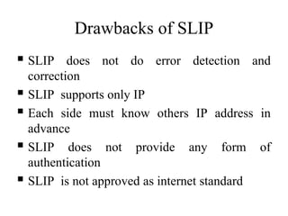
Drawbacks of SLIP
SLIP does not do error detection and
correction
SLIP supports only IP
Each side must know others IP address in
advance
SLIP does not provide any form of
authentication
SLIP is not approved as internet standard
195.
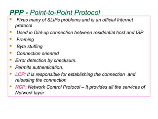
PPP - Point-to-PointProtocol
Fixes many of SLIPs problems and is an official Internet
protocol
Used in Dial-up connection between residential host and ISP
Framing
Byte stuffing
Connection oriented
Error detection by checksum.
Permits authentication.
LCP: It is responsible for establishing the connection and
releasing the connection
NCP: Network Control Protocol – It provides all the services of
Network layer
196.
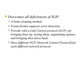
Overcomes alldeficiencies of SLIP.
A better framing method.
Frame format supports error detection.
Provide with a Link Control protocol (LCP), for
bringing lines up, testing them, negotiating options,
and bringing then down back.
Have different NCP (Network Control Protocol) for
each different network protocol.
197.
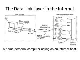
The Data LinkLayer in the Internet
A home personal computer acting as an internet
host.
A home personal computer acting as an internet host.
198.
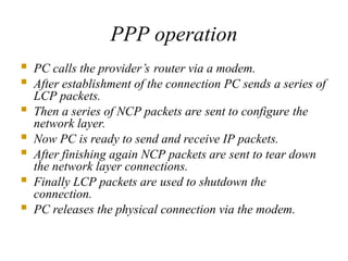
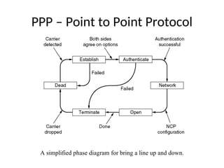
PPP operation
PCcalls the provider’s router via a modem.
After establishment of the connection PC sends a series of
LCP packets.
Then a series of NCP packets are sent to configure the
network layer.
Now PC is ready to send and receive IP packets.
After finishing again NCP packets are sent to tear down
the network layer connections.
Finally LCP packets are used to shutdown the
connection.
PC releases the physical connection via the modem.
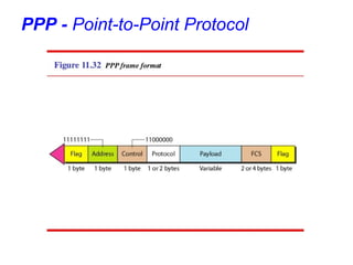
• Flag: APPP frame starts and ends with a 1-byte flag with the bit
pattern 01111110.It is a byte-oriented protocol. The flag is treated as
a byte.
• Address: It is a constant value and is set to 11111111(broadcast
address).During negotiation, the two parties may agree to omit this
byte.
• Control:11000000(imitating U-frame in HDLC).PPP does not
provide any flow control. Error control is also limited to error
detection.
• Protocol: It defines what is being carried in the data field: either user
data or other information.
• Payload field: It carries either the user data or other information. The
default of max..1500 bytes.
• FCS: 2-bytes or 4-bytes standard CRC.
201.
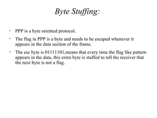
Byte Stuffing:
• PPPis a byte oriented protocol.
• The flag in PPP is a byte and needs to be escaped whenever it
appears in the data section of the frame.
• The esc byte is 01111101,means that every time the flag like pattern
appears in the data, this extra byte is stuffed to tell the receiver that
the next byte is not a flag.
202.
PPP – Pointto Point Protocol
A simplified phase diagram for bring a line up and down.
203.
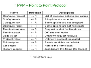
l
PPP – Pointto Point Protocol
• The LCP frame types.
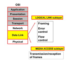
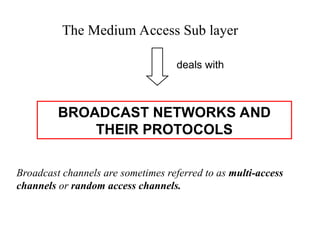
BROADCAST NETWORKS AND
THEIRPROTOCOLS
The Medium Access Sub layer
deals with
Broadcast channels are sometimes referred to as multi-access
channels or random access channels.
207.
Topics
Introduction
ChannelAllocation problem
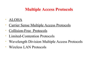
Multiple Access Protocols
IEEE Standard 802 for LANs
Wireless LAN
Bridges & its types.
208.
Introduction
Medium AccessControl (MAC) sub layer is
part of Data Link layer.
In fact, it is the bottom part of DLL
(interfacing with the physical layer)
Deals with broadcast networks
209.
The Channel AllocationProblem
1. Static Channel Allocation in LANs and MANs
2. Dynamic Channel Allocation in LANs and
MANs
210.
Channel Allocation problem
StaticChannel Allocation in LANs and MANs
FDM & TDM
FDM: Frequency Division Multiplexing
1.The traditional way of allocating a single channel, among
multiple competing users is Frequency division
multiplexing(FDM).
2. If there are N users, the bandwidth is divided into N equal-sized
portions, each user being assigned one portion.
3. Here each user has a private frequency band, there is no
interference between users.
211.
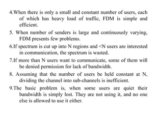
4.When there isonly a small and constant number of users, each
of which has heavy load of traffic, FDM is simple and
efficient.
5. When number of senders is large and continuously varying,
FDM presents few problems.
6.If spectrum is cut up into N regions and <N users are interested
in communication, the spectrum is wasted.
7.If more than N users want to communicate, some of them will
be denied permission for lack of bandwidth.
8. Assuming that the number of users be held constant at N,
dividing the channel into sub-channels is inefficient.
9.The basic problem is, when some users are quiet their
bandwidth is simply lost. They are not using it, and no one
else is allowed to use it either.
212.
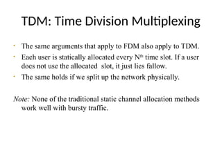
TDM: Time DivisionMultiplexing
• The same arguments that apply to FDM also apply to TDM.
• Each user is statically allocated every Nth
time slot. If a user
does not use the allocated slot, it just lies fallow.
• The same holds if we split up the network physically.
Note: None of the traditional static channel allocation methods
work well with bursty traffic.
213.
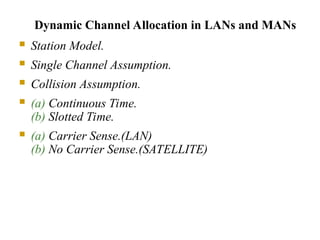
Dynamic Channel Allocationin LANs and MANs
Station Model.
Single Channel Assumption.
Collision Assumption.
(a) Continuous Time.
(b) Slotted Time.
(a) Carrier Sense.(LAN)
(b) No Carrier Sense.(SATELLITE)
214.
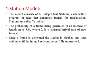
1.Station Model:
• Themodel consists of N independent Stations, each with a
program or user that generates frames for transmission.
Stations are called Terminals.
• The probability of a frame being generated in an interval of
length Δt is λΔt, where λ is a constant(arrival rate of new
frames).
• Once a frame is generated the station is blocked and does
nothing until the frame has been successfully transmitted.
215.
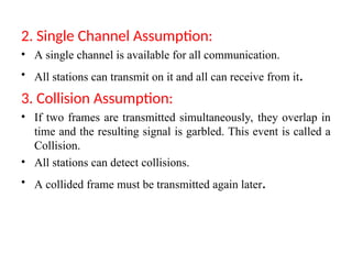
2. Single ChannelAssumption:
• A single channel is available for all communication.
• All stations can transmit on it and all can receive from it.
3. Collision Assumption:
• If two frames are transmitted simultaneously, they overlap in
time and the resulting signal is garbled. This event is called a
Collision.
• All stations can detect collisions.
• A collided frame must be transmitted again later.
216.
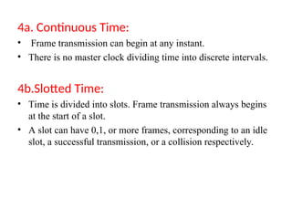
4a. Continuous Time:
•Frame transmission can begin at any instant.
• There is no master clock dividing time into discrete intervals.
4b.Slotted Time:
• Time is divided into slots. Frame transmission always begins
at the start of a slot.
• A slot can have 0,1, or more frames, corresponding to an idle
slot, a successful transmission, or a collision respectively.
217.
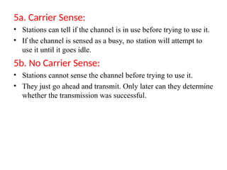
5a. Carrier Sense:
•Stations can tell if the channel is in use before trying to use it.
• If the channel is sensed as a busy, no station will attempt to
use it until it goes idle.
5b. No Carrier Sense:
• Stations cannot sense the channel before trying to use it.
• They just go ahead and transmit. Only later can they determine
whether the transmission was successful.
Medium Access SubLayer
ALOHA
Pure ALOHA (Mr. Norman Abramson in 1970s)
Slotted ALOHA (Mr.Roberts in 1972)
ALOHA system used to ground based radio broadcasting.
220.
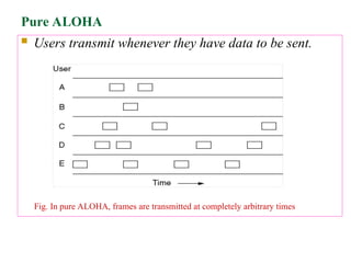
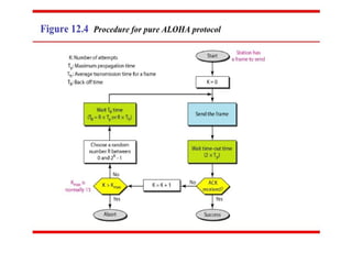
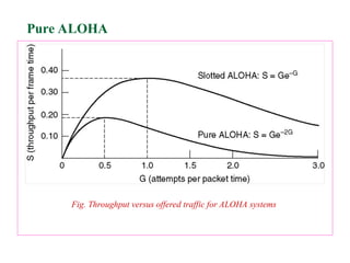
Pure ALOHA
Userstransmit whenever they have data to be sent.
Fig. In pure ALOHA, frames are transmitted at completely arbitrary times
221.
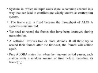
• Systems inwhich multiple users share a common channel in a
way that can lead to conflicts are widely known as contention
system.
• The frame size is fixed because the throughput of ALOHA
systems is maximized.
• We need to resend the frames that have been destroyed during
transmission.
• A collision involves two or more stations. If all these try to
resend their frames after the time-out, the frames will collide
again.
• Pure ALOHA states that when the time-out period passes, each
station waits a random amount of time before resending its
frame(TB).
222.
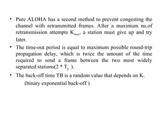
• Pure ALOHAhas a second method to prevent congesting the
channel with retransmitted frames. After a maximum no.of
retransmission attempts Kmax, a station must give up and try
later.
• The time-out period is equal to maximum possible round-trip
propagation delay, which is twice the amount of the time
required to send a frame between the two most widely
separated stations(2 * Tp ).
• The back-off time TB is a random value that depends on K.
(binary exponential back-off )
225.
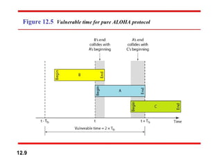
Whenever twoframes try to occupy the channel at the
same time, there will be a collision and both will be
garbled.
If the first bit of the new frame overlaps with the last bit
of a frame almost finished , both frames will be totally
destroyed, and both will be retransmitted later.
Throughput for pure ALOHA decreases.
Pure ALOHA
226.
Disadvantage
More numberof users share common channels in a
way that can lead to conflicts.
More number of collisions occur.
Collision detected: stations waits a random amount of
time.
Pure ALOHA
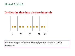
Slotted ALOHA
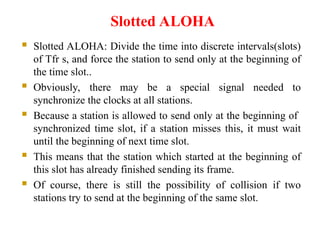
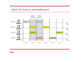
SlottedALOHA: Divide the time into discrete intervals(slots)
of Tfr s, and force the station to send only at the beginning of
the time slot..
Obviously, there may be a special signal needed to
synchronize the clocks at all stations.
Because a station is allowed to send only at the beginning of
synchronized time slot, if a station misses this, it must wait
until the beginning of next time slot.
This means that the station which started at the beginning of
this slot has already finished sending its frame.
Of course, there is still the possibility of collision if two
stations try to send at the beginning of the same slot.
230.
However, thevulnerable time is now reduced to one-half,
equal to Tfr.
It can be proved that the average number of successful
transmission for the slotted ALOHA is S=G * e-G
Maximum throughput occurs at G=1, S=1/e or 0.368. This is
twice that of pure ALOHA protocol.
In other words, if a frame is generated during one frame
transmission time, then 36.8 % of these frames reach their
destination successfully. This result is expected because
vulnerable time is equal to the frame transmission time.
Therefore, if a station generates only one frame in this
vulnerable time(and no other station generates a frame during
this time), the frame will be reach its destination successfully.
231.
Slotted ALOHA
Divides thetime into discrete intervals
A B C D E
Disadvantage: collisions Throughput for slotted ALOHA
increases.
232.
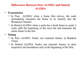
Differences Between PureALOHA and Slotted
ALOHA
• Transmission
• In Pure ALOHA when a frame first arrives, the node
immediately transmits the frame in its entirely into the
Broadcast Channel.
• In Slotted ALOHA when a node has a fresh frame to send, it
waits until the beginning of the next slot and transmits the
entire frame in the slot.
• Timing
• In Pure ALOHA Nodes can transmit frames at Random
Times.
• In Slotted ALOHA Nodes can transmit frames in their
respective slot boundaries only at the beginning of the Slot.
233.
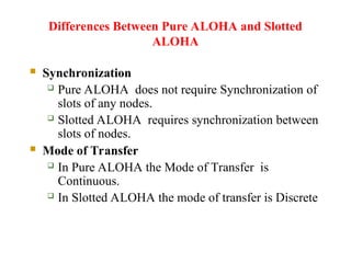
Differences Between PureALOHA and Slotted
ALOHA
Synchronization
Pure ALOHA does not require Synchronization of
slots of any nodes.
Slotted ALOHA requires synchronization between
slots of nodes.
Mode of Transfer
In Pure ALOHA the Mode of Transfer is
Continuous.
In Slotted ALOHA the mode of transfer is Discrete
234.
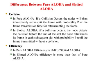
Differences Between PureALOHA and Slotted
ALOHA
Collision
In Pure ALOHA If a Collision Occurs the nodes will then
immediately retransmit the frame with probability P or the
frame transmission time for retransmitting the frame.
In Slotted ALOHA, if a collision occurs, the node detects
the collision before the end of the slot the node retransmits
its frame in each subsequent slot with probability P until the
frame transmitted without a collision.
Efficiency
In Pure ALOHA Efficiency is Half of Slotted ALOHA.
In Slotted ALOHA efficiency is more than that of Pure
ALOHA.
235.
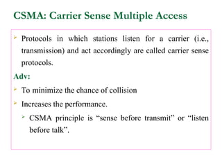
CSMA: Carrier SenseMultiple Access
Protocols in which stations listen for a carrier (i.e.,
transmission) and act accordingly are called carrier sense
protocols.
Adv:
To minimize the chance of collision
Increases the performance.
CSMA principle is “sense before transmit” or “listen
before talk”.
236.
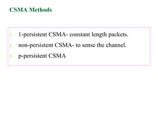
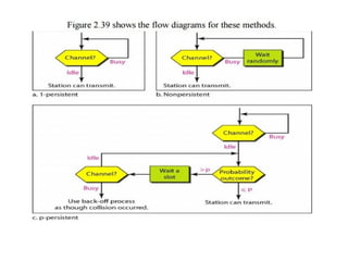
CSMA Methods
1. 1-persistentCSMA- constant length packets.
2. non-persistent CSMA- to sense the channel.
3. p-persistent CSMA
238.
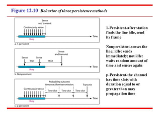
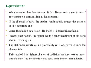
1-persistent
When astation has data to send, it first listens to channel to see if
any one else is transmitting at that moment.
If the channel is busy, the station continuously senses the channel
until it becomes idle.
When the station detects an idle channel, it transmits a frame.
If a collision occurs, the station waits a random amount of time and
starts all over again.
The station transmits with a probability of 1 whenever if finds the
channel idle.
This method has highest chance of collision because two or more
stations may find the line idle and send their frames immediately.
239.
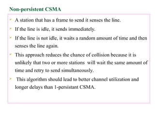
Non-persistent CSMA
Astation that has a frame to send it senses the line.
If the line is idle, it sends immediately.
If the line is not idle, it waits a random amount of time and then
senses the line again.
This approach reduces the chance of collision because it is
unlikely that two or more stations will wait the same amount of
time and retry to send simultaneously.
This algorithm should lead to better channel utilization and
longer delays than 1-persistant CSMA.
240.
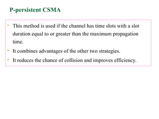
P-persistent CSMA
Thismethod is used if the channel has time slots with a slot
duration equal to or greater than the maximum propagation
time.
It combines advantages of the other two strategies.
It reduces the chance of collision and improves efficiency.
241.
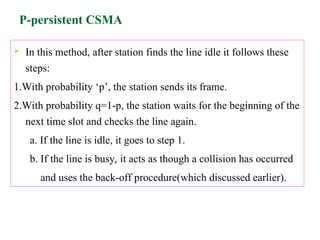
P-persistent CSMA
Inthis method, after station finds the line idle it follows these
steps:
1.With probability ‘p’, the station sends its frame.
2.With probability q=1-p, the station waits for the beginning of the
next time slot and checks the line again.
a. If the line is idle, it goes to step 1.
b. If the line is busy, it acts as though a collision has occurred
and uses the back-off procedure(which discussed earlier).
243.
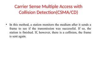
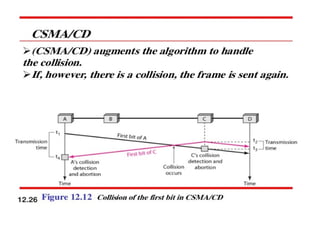
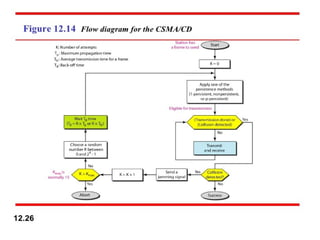
Carrier Sense MultipleAccess with
Collision Detection(CSMA/CD)
• In this method, a station monitors the medium after it sends a
frame to see if the transmission was successful. If so, the
station is finished. If, however, there is a collision, the frame
is sent again.
246.
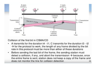
Minimum Frame Size
•For CSMA/CD to work, we need restriction on the frame size.
• Therefore, the frame transmission time Tfr must be at least
two times the maximum propagation time Tp.
• To understand the reason, let us think about worst-case
scenario. If two stations involved in a collision are the
maximum distance apart, the signal from the first takes Tp to
reach the second, and the effect of the collision takes another
Tp to reach the first.
• So the requirement is that the first station must still be
transmitting after 2Tp
248.
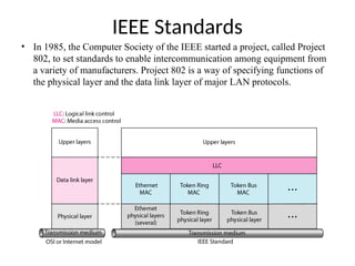
IEEE Standards
• In1985, the Computer Society of the IEEE started a project, called Project
802, to set standards to enable intercommunication among equipment from
a variety of manufacturers. Project 802 is a way of specifying functions of
the physical layer and the data link layer of major LAN protocols.
249.
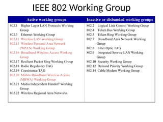
IEEE 802 WorkingGroup
Active working groups Inactive or disbanded working groups
802.1 Higher Layer LAN Protocols Working
Group
802.3 Ethernet Working Group
802.11 Wireless LAN Working Group
802.15 Wireless Personal Area Network
(WPAN) Working Group
802.16 Broadband Wireless Access Working
Group
802.17 Resilient Packet Ring Working Group
802.18 Radio Regulatory TAG
802.19 Coexistence TAG
802.20 Mobile Broadband Wireless Access
(MBWA) Working Group
802.21 Media Independent Handoff Working
Group
802.22 Wireless Regional Area Networks
802.2 Logical Link Control Working Group
802.4 Token Bus Working Group
802.5 Token Ring Working Group
802.7 Broadband Area Network Working
Group
802.8 Fiber Optic TAG
802.9 Integrated Service LAN Working
Group
802.10 Security Working Group
802.12 Demand Priority Working Group
802.14 Cable Modem Working Group
250.
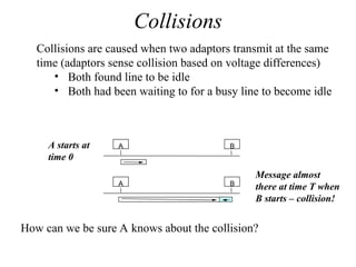
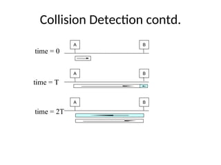
Collisions
A B
A B
Collisionsare caused when two adaptors transmit at the same
time (adaptors sense collision based on voltage differences)
• Both found line to be idle
• Both had been waiting to for a busy line to become idle
A starts at
time 0
Message almost
there at time T when
B starts – collision!
How can we be sure A knows about the collision?
251.
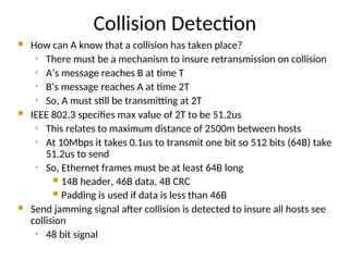
Collision Detection
Howcan A know that a collision has taken place?
• There must be a mechanism to insure retransmission on collision
• A’s message reaches B at time T
• B’s message reaches A at time 2T
• So, A must still be transmitting at 2T
IEEE 802.3 specifies max value of 2T to be 51.2us
• This relates to maximum distance of 2500m between hosts
• At 10Mbps it takes 0.1us to transmit one bit so 512 bits (64B) take
51.2us to send
• So, Ethernet frames must be at least 64B long
14B header, 46B data, 4B CRC
Padding is used if data is less than 46B
Send jamming signal after collision is detected to insure all hosts see
collision
• 48 bit signal
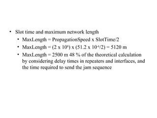
• Slot timeand maximum network length
• MaxLength = PropagationSpeed x SlotTime/2
• MaxLength = (2 x 10⁸
) x (51.2 x 10⁻⁶
/2) = 5120 m
• MaxLength = 2500 m 48 % of the theoretical calculation
by considering delay times in repeaters and interfaces, and
the time required to send the jam sequence
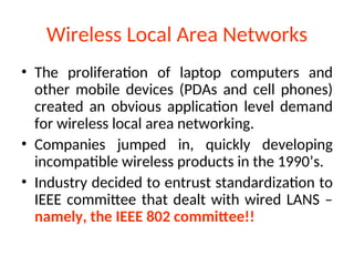
Wireless Local AreaNetworks
• The proliferation of laptop computers and
other mobile devices (PDAs and cell phones)
created an obvious application level demand
for wireless local area networking.
• Companies jumped in, quickly developing
incompatible wireless products in the 1990’s.
• Industry decided to entrust standardization to
IEEE committee that dealt with wired LANS –
namely, the IEEE 802 committee!!
256.
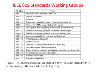
IEEE 802 StandardsWorking Groups
Figure 1-38. The important ones are marked with *. The ones marked with
are hibernating. The one marked with † gave up.
257.
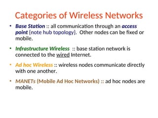
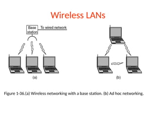
Categories of WirelessNetworks
• Base Station :: all communication through an access
point {note hub topology}. Other nodes can be fixed or
mobile.
• Infrastructure Wireless :: base station network is
connected to the wired Internet.
• Ad hoc Wireless :: wireless nodes communicate directly
with one another.
• MANETs (Mobile Ad Hoc Networks) :: ad hoc nodes are
mobile.
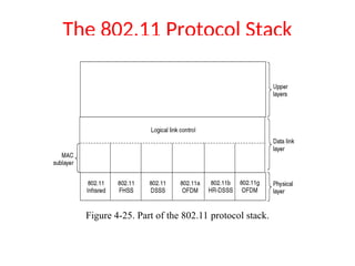
Wireless Physical Layer
•Physical layer conforms to OSI (five options)
– 1997: 802.11 infrared, FHSS, DHSS
– 1999: 802.11a OFDM and 802.11b HR-DSSS
– 2001: 802.11g OFDM
• 802.11 Infrared
– Two capacities 1 Mbps or 2 Mbps.
– Range is 10 to 20 meters and cannot penetrate walls.
– Does not work outdoors.
• 802.11 FHSS (Frequence Hopping Spread Spectrum)
– The main issue is multipath fading.
– 79 non-overlapping channels, each 1 Mhz wide at low end of 2.4
GHz ISM band.
– Same pseudo-random number generator used by all stations.
– Dwell time: min. time on channel before hopping (400msec).
261.
Wireless Physical Layer
•802.11 DSSS (Direct Sequence Spread Spectrum)
– Spreads signal over entire spectrum using pseudo-random
sequence (similar to CDMA see Tanenbaum sec. 2.6.2).
– Each bit transmitted using an 11 chips Barker sequence, PSK at
1Mbaud.
– 1 or 2 Mbps.
• 802.11a OFDM (Orthogonal Frequency Divisional Multiplexing)
– Compatible with European HiperLan2.
– 54Mbps in wider 5.5 GHz band transmission range is limited.
– Uses 52 FDM channels (48 for data; 4 for synchronization).
– Encoding is complex ( PSM up to 18 Mbps and QAM above this
capacity).
– E.g., at 54Mbps 216 data bits encoded into into 288-bit symbols.
– More difficulty penetrating walls.
262.
Wireless Physical Layer
•802.11b HR-DSSS (High Rate Direct Sequence Spread
Spectrum)
– 11a and 11b shows a split in the standards committee.
– 11b approved and hit the market before 11a.
– Up to 11 Mbps in 2.4 GHz band using 11 million chips/sec.
– Note in this bandwidth all these protocols have to deal
with interference from microwave ovens, cordless phones
and garage door openers.
– Range is 7 times greater than 11a.
263.
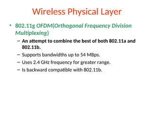
Wireless Physical Layer
•802.11g OFDM(Orthogonal Frequency Division
Multiplexing)
– An attempt to combine the best of both 802.11a and
802.11b.
– Supports bandwidths up to 54 MBps.
– Uses 2.4 GHz frequency for greater range.
– Is backward compatible with 802.11b.
264.
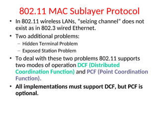
802.11 MAC SublayerProtocol
• In 802.11 wireless LANs, “seizing channel” does not
exist as in 802.3 wired Ethernet.
• Two additional problems:
– Hidden Terminal Problem
– Exposed Station Problem
• To deal with these two problems 802.11 supports
two modes of operation DCF (Distributed
Coordination Function) and PCF (Point Coordination
Function).
• All implementations must support DCF, but PCF is
optional.
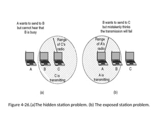
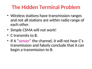
The Hidden TerminalProblem
• Wireless stations have transmission ranges
and not all stations are within radio range of
each other.
• Simple CSMA will not work!
• C transmits to B.
• If A “senses” the channel, it will not hear C’s
transmission and falsely conclude that A can
begin a transmission to B.
267.
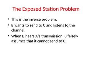
The Exposed StationProblem
• This is the inverse problem.
• B wants to send to C and listens to the
channel.
• When B hears A’s transmission, B falsely
assumes that it cannot send to C.
268.
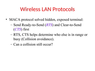
Wireless LAN Protocols
•MACA protocol solved hidden, exposed terminal:
– Send Ready-to-Send (RTS) and Clear-to-Send
(CTS) first
– RTS, CTS helps determine who else is in range or
busy (Collision avoidance).
– Can a collision still occur?
269.
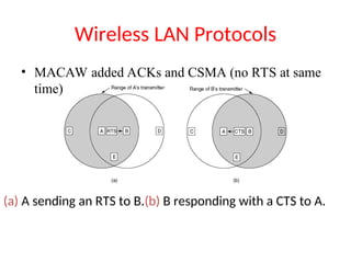
Wireless LAN Protocols
•MACAW added ACKs and CSMA (no RTS at same
time)
(a) A sending an RTS to B.(b) B responding with a CTS to A.
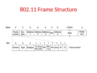
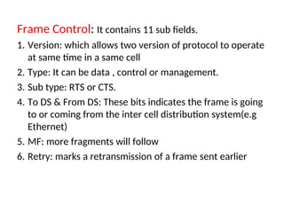
Frame Control: Itcontains 11 sub fields.
1. Version: which allows two version of protocol to operate
at same time in a same cell
2. Type: It can be data , control or management.
3. Sub type: RTS or CTS.
4. To DS & From DS: These bits indicates the frame is going
to or coming from the inter cell distribution system(e.g
Ethernet)
5. MF: more fragments will follow
6. Retry: marks a retransmission of a frame sent earlier
272.
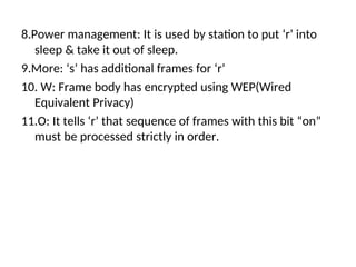
8.Power management: Itis used by station to put ‘r’ into
sleep & take it out of sleep.
9.More: ‘s’ has additional frames for ‘r’
10. W: Frame body has encrypted using WEP(Wired
Equivalent Privacy)
11.O: It tells ‘r’ that sequence of frames with this bit “on”
must be processed strictly in order.
273.
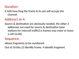
Duration:
It tells howlong the frame & its ack will occupy the
channel.
Address1 to 4:
Source & destination are obviously needed, the other 2
addresses are used for source & destination base
stations for intercell traffic(i.e frames may enter or leave
a cell via BS)
Sequence:
allows fragments to be numbered.
Out of 16 bits,12 identify frame, 4 identify fragment
274.
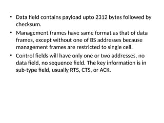
• Data fieldcontains payload upto 2312 bytes followed by
checksum.
• Management frames have same format as that of data
frames, except without one of BS addresses because
management frames are restricted to single cell.
• Control fields will have only one or two addresses, no
data field, no sequence field. The key information is in
sub-type field, usually RTS, CTS, or ACK.
275.
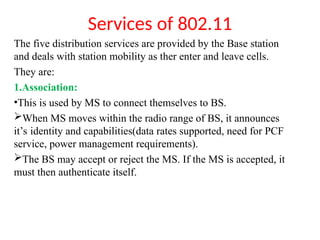
Services of 802.11
Thefive distribution services are provided by the Base station
and deals with station mobility as ther enter and leave cells.
They are:
1.Association:
•This is used by MS to connect themselves to BS.
When MS moves within the radio range of BS, it announces
it’s identity and capabilities(data rates supported, need for PCF
service, power management requirements).
The BS may accept or reject the MS. If the MS is accepted, it
must then authenticate itself.
276.
2. Disassociation:
Eitherthe station or BS may disassociate, thus breaking the
relationship.
A station should use this service before shutting down or
leaving, but the BS may also use it before going down for
maintenance.
3. Reassociation:
A station may change its preferred BS using this service.
This facility is useful for MSs moving from one cell to another


![Byte Stuffing
[HDLC Example]
• Also referred to as character stuffing.
• ASCII characters are used as framing delimiters
(e.g. DLE STX and DLE ETX)
• The problem occurs when these character
patterns occur within the “transparent” data.
Solution: sender stuffs an extra DLE into the data
stream just before each occurrence of an
“accidental” DLE in the data stream.
The data link layer on the receiving end unstuffs the
DLE before giving the data to the network layer.](https://image.slidesharecdn.com/jntuhs-11-12-2024-250627021452-9461a311/85/JNTUHS-11-12-2024-ppt-computer-networks-notes-110-320.jpg)
![DLE STX DLE ETX
Transparent Data
DLE STX DLE ETX
A B DLE H W
DLE STX DLE ETX
A B DLE H W
DLE
DLE STX DLE ETX
A B DLE H W
Stuffed
Unstuffed
Before
Byte Stuffing
[HDLC Example]](https://image.slidesharecdn.com/jntuhs-11-12-2024-250627021452-9461a311/85/JNTUHS-11-12-2024-ppt-computer-networks-notes-111-320.jpg)
![Computer Networks: Bit and Byte Stuffing 112
Bit Stuffing
• Each frame begins and ends with a special bit
pattern called a flag byte [01111110]. {Note this is
7E in hex}
• Whenever sender data link layer encounters five
consecutive ones in the data stream, it
automatically stuffs a 0 bit into the outgoing
stream.
• When the receiver sees five consecutive incoming
ones followed by a 0 bit, it automatically destuffs
the 0 bit before sending the data to the network
layer.](https://image.slidesharecdn.com/jntuhs-11-12-2024-250627021452-9461a311/85/JNTUHS-11-12-2024-ppt-computer-networks-notes-112-320.jpg)