SlideShare a Scribd company logo
1 of 14
Download to read offline
E2-E3/Electrical Rev date: 01-04-2011
BSNL, India For Internal Circulation Only Page: 1
E2-E3: ELECTRICAL
CHAPTER-16
EARTHING
E2-E3/Electrical Rev date: 01-04-2011
BSNL, India For Internal Circulation Only Page: 2
Earthing
Introduction:
Earthing is an essential part of any electric /electronic system. Utmost care is required to
be taken for provision of proper and effective Earthing for various telecom installations.
This chapter discusses about various types of Earthing, which are used in Telecom
Installations.
Objective:
After the end of this chapter, the participants would be able to know:
Objective of Earthing
Requirement of effective Earthing
Various types of earthing used in telecom installations
Objective of Earthing System:
The objective of Earthing system may be summarized as follows:-
a) Reduction of Crosstalk and Noise:-
On pole of the battery (+Ve pole) is earthed in the telephone exchange so that cross talk
between the various circuits due to the speech currents of one circuit finding path through
the other via common battery feed points of the transmission bridge and reduced NSN via
earthed terminal of the battery.
b) Earth is used to afford convenience & “reliability, in the operate path of the ircuits
involved in the switching apparatus of telecom circuits.
c) Used as return path for the conductor in some telegraph and voice circuits.
d) Protection of costly apparatus and persons against foreign voltages and leakage
currents from power wirings to the metallic frame of the equipment.
e) Protection of buildings and equipments from lighting strikes.
f) Earthing power supply systems is used to effect reliability of power as it helps to
provide stability of voltage conditions preventing excess fluctuations and providing a
measure of protection against lighting.
E2-E3/Electrical Rev date: 01-04-2011
BSNL, India For Internal Circulation Only Page: 3
g) To divert stray RF energy from sensitive audio, video control and computer
equipments.
Requirements for Effective Earthing:
An earthing system must meet the following specifications :-
1. The resistance to the earth must be within allowable limit for the particular
application.
2. The electrode buried in ground must be :
a) Having good electrical conductivity to carry highest specified load current .
b) Immune to the corrosive action of the soil all along the period .
c) Of sufficient mechanical strength to enable them to be installed without any
damage .
d) Inert i.e. must not be a source of galvanic corrosion current within the system to
be protected.
3. The earth electrode must provide as much as area of contact as possible with the
soil to reduce the resistance of the current path to the earth.
4. The resistance of the earth connection must remain within the allowable specified
limit throughout the session
Classes of Earthing systems:
Eathing systems are provided to serve many different purposes. They may be divided in
two major categories, viz
a) Service Earthing systems
b) Protective Earthing System
a) Service Earthing systems:-
Equipment earthing for switching , transmission ,measuring equipments etc.
b) Protective Earthing System:-
i. Power system earth to provide protection against excessive current.
ii. Lighting protective earth to provide protection against excessive voltage.
Requirements for Service Earthing System:
In general, service earthing system should have a low D.C. resistance to the general body
of the earth. In order to ensure that the potential drop across the earth connection is low.
If any current flows through the service earthing system, a potential difference will be
E2-E3/Electrical Rev date: 01-04-2011
BSNL, India For Internal Circulation Only Page: 4
developed across the earth connection. This can introduce interference in the form of
electrical noise into any telecommunication circuit connected to that earthing system.
The value of resistance which must be met by a service earthing will depend on the
purposes for which the earth likely to be carried by the earthing system, and the tolerable
voltage drop across the earth connection.
Requirements for protective Earthing System:
The Requirements to be satisfied by a protective earthing system are governed by the
purpose for which the earth is being provided earths which protect against excessive
current (e.g. power supply protective earth) must have low resistance in order to:
a) Carry the anticipated value of over current without overheating and “burning out”
b) Enable sufficient current flow to ground to ensure that any over current
disconnected the current after a very short time.
c) Prevent hazardous potential differences to develop across the earth connection,
Excessive potential differences can cause breakdown of insulation, and danger to life and
limb). The foregoing requirements can be satisfied by heavy gauge conductors of very
low resistance connected to earthing systems of very low resistance (typically les than on
ohm)
d) Able to withstand indefinitely the corrosive action of soil
e) Inert in relation to the system to be protected (i.e must not be a source of galvanic
corrosion currents)
f) The resistance of the earth connection must remain reasonably constant
throughout the various seasons of the year.
g) Earths which protect against excessive voltage (e.g. earths connected to lighting
protection systems) must posses a low surge impedance in order to enable the lighting
surge currents to be easily conveyed to the earth and thus diverted away from the
equipment which is to be protected form the lighting.
Separate Earths Vs common Earth:
E2-E3/Electrical Rev date: 01-04-2011
BSNL, India For Internal Circulation Only Page: 5
Attempts to provide separate earthing system for different purposes at a common location
have generally proved to be unsatisfactory for the following reasons:
a) In practice it usually not possible to ensure that there is no electrical coupling
between separate earthing systems in close proximity. This is because of casual and
uncontrolled interconnections with in the installation, and also because of galvanic
coupling in the ground
b) There is a risk of fire, and a risk of danger to human life, because a difference in
potential between various earths might cause excessive current and/or excessive voltage.
c) Currents may flow through the structure or between various earthing systems and
cause corrosion.
On the other hand separate earths have in the post been thought desirable for certain
categories of service earth. This has usually been done an attempt to eliminate noise from
the telecommunication circuits.
Most authorities now consider that it is for battery not to try to provide separate earthing
systems, but to provide a common Earthing system at an installation, and to design and
install it in such a way that it satisfies the requirements of the various earthing systems
which are required at that installation.
If the ground resistively near an installation is high, it may be necessary to provide part of
the earth electrode installation at some distance away where the ground resistivity is
better. In such cases an earth electrode system close the building should be provided for
lighting protection and this should be interconnected with the remote electrode system
The main advantage of a common earthing system are:-
a) By care fully bonding the various earthing systems together, the potential
difference between on earth connection and another is negligible. Thus no excessive
current or voltages will be developed within the earthing system.
Safety grounding & Inter system Ground Noise:
A computer equipment is equipped with three wire grounding type AC power connectors.
Many type of equipment, such as lamps, have only two wire type plugs since two wires
are all that is necessary to deliver AC power, the third wire is a safety ground wire, which
is connected to all exposed exterior metal parts on the computer equipment the grounding
connection provided at the wall receptacle is connected within the building to copper
E2-E3/Electrical Rev date: 01-04-2011
BSNL, India For Internal Circulation Only Page: 6
water popes and/or structural metal parts of the building. The purpose of this arrangement
is to protect the user form electrical shock when the exposed metal parts of a faulty
computer and building structural metal parts are touched. For safety exposed devices
such as RS-232 connectors and printer ports are considered to be exposed metal parts.
For this reason, the voltage at any connector pin must be ground or present a small
voltage with respect to ground. The result is that in virtually all computer equipment, the
CPU common wire or ground reference is connected to the safety grounding wire (and
the enclosure) of the equipment.
In the system including equipment that is arrangement leads to a conflict. Every
interconnect device has two connections, which are attempting to establish the common
reference voltage for date communications:
1. The common wire in the date line, which connects the device to other equipment
2. The device’s safety grounding wire
The situation is sometime knows as a “ground loop”. The existence of the loop can lead
to differences between the common reference voltage between any interconnected
devices must not be confused with other power problems such as common mode noise,
normal mode noise, EMI, or RFI. These ground voltage differences are referred to as
INTER-SYSTEM GROUND NOISE.
Design Principles for Earthing System:
Earthing systems should be designed to achieve the following:-
a) Adequate current capacity (DC or AC as appropriate)
b) Adequate mechanical strength to withstand the rigours of service without
fracturing.
c) In the case of lighting protective earths adequate-surge-current carrying ability.
Installation of Ring Earth around new telecom departmental building:
A trench, 30 cms wide and normally 150 cms deep is dug. The depth should be 1-1.5 mt.
In case of rocky area the depth may be 60-90 cms. GI strip of size 50 x 3 mm is laid in
the trench. The joints are properly wrapped and sealed by waterproof tape.
E2-E3/Electrical Rev date: 01-04-2011
BSNL, India For Internal Circulation Only Page: 7
In case of new building ring earth should act as the equipotential bonding and all earthing
equipments are to be extended from the ring earth
Where is difficult to lay ring earth such as private/ rented building due to space constants
the plate/ spike earth may be used.
Telephone Exchange:-
The main requirements of the earthing system at a telephone system at a telephone
exchange are:
a) To provide a low resistance path of ground.
b) To be able discharge the maximum anticipated current which the earth system as
expected to carry, both under working conditions and under fault conditions.
Earthing of antenna Towers mounted on top of building
For earthing of tower on top of a building, 50 x3 GI Strip down lead should be bonded to
any two opposite tower legs and brought down along out side of the building and
connected to the ring earth.
Earthing of Waveguides:
The wave guide for UHF/VHF which are aluminum and that for mico wave system which
are proper wave guide are mounted on the tower and connected to antenna. all such wave
guide should be individually earth ed at the top and at bottom of the tower and at in –
between intervals by earthing kits as recommended by the manufacture
Service Earths:
Service earth which carry current (e.g.teleprinter earths which may carry 20- 25 mA)
must be capable of surviving the discharge of such current to ground for their flowing
through a steel earth electrode .
Earth electrode Materials:
Since copper is a good electrical conductor,t here is a great temptation to use copper as
the material; for earth electrodes, e.g. bare copper wire copper plates, copper-clad steel
rods, etc. However, due to the position of copper in the electrochemical series it rapidly
causes correction of steel, Zinc lead aluminum etc. thus the use of copper as an earthing
E2-E3/Electrical Rev date: 01-04-2011
BSNL, India For Internal Circulation Only Page: 8
material requires very careful attention to the prevention of corrosion and it is usually
better to chooses some other metal e.g. galvanized steel, plain steel stainless steel etc.
Spike Earth :
Spike electrodes consist of mental rods or pipes driven vertically into the ground copper,
stainless steel and mild steel are the most suitable material being corrosion resistant used
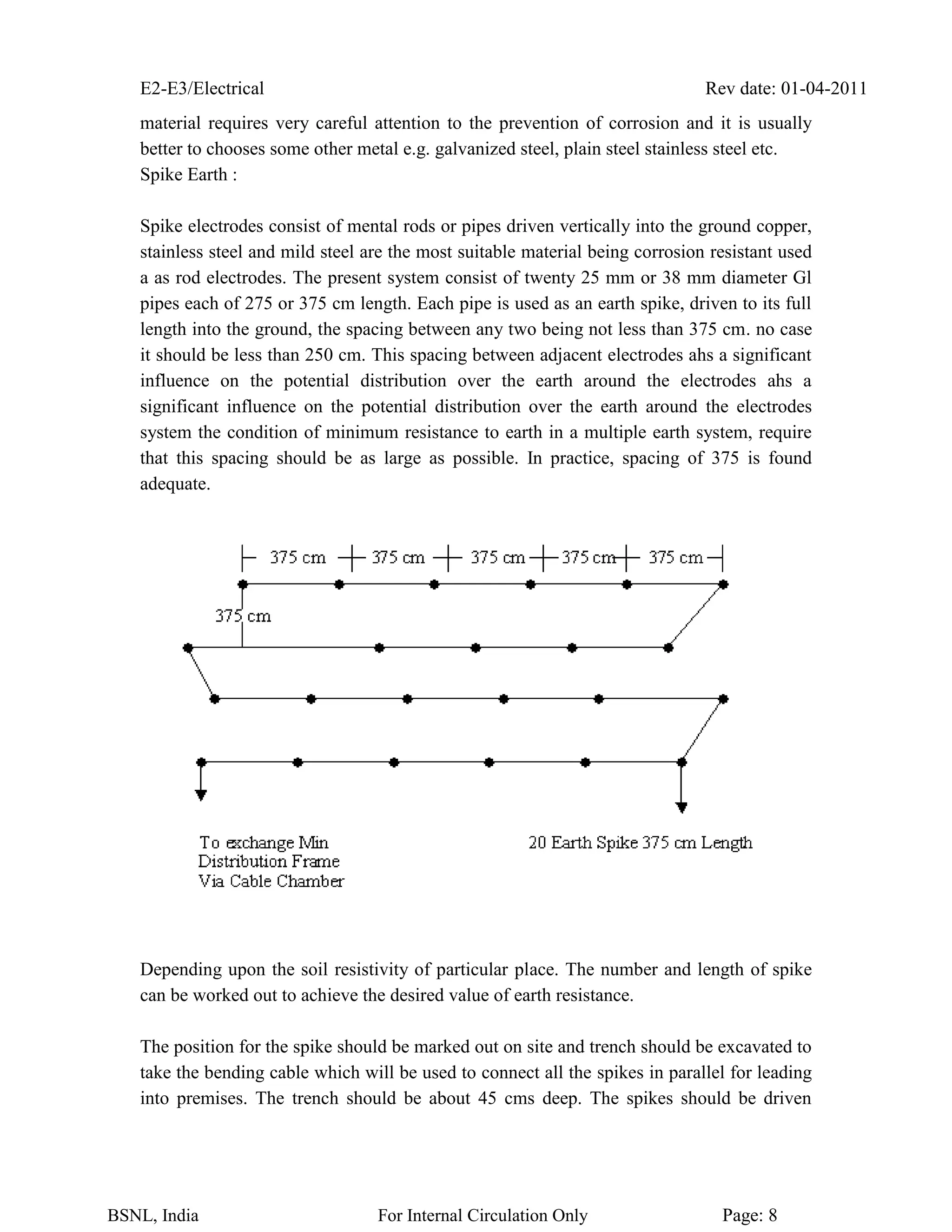
a as rod electrodes. The present system consist of twenty 25 mm or 38 mm diameter Gl
pipes each of 275 or 375 cm length. Each pipe is used as an earth spike, driven to its full
length into the ground, the spacing between any two being not less than 375 cm. no case
it should be less than 250 cm. This spacing between adjacent electrodes ahs a significant
influence on the potential distribution over the earth around the electrodes ahs a
significant influence on the potential distribution over the earth around the electrodes
system the condition of minimum resistance to earth in a multiple earth system, require
that this spacing should be as large as possible. In practice, spacing of 375 is found
adequate.
Depending upon the soil resistivity of particular place. The number and length of spike
can be worked out to achieve the desired value of earth resistance.
The position for the spike should be marked out on site and trench should be excavated to
take the bending cable which will be used to connect all the spikes in parallel for leading
into premises. The trench should be about 45 cms deep. The spikes should be driven
E2-E3/Electrical Rev date: 01-04-2011
BSNL, India For Internal Circulation Only Page: 9
vertically into the trench until the top of the driving head is 30 cms above the bottom of
the excavation.
A driving head or suitable size bolt is supplied with each spike and this must be used to
prevent the top of the spike being damaged during driving operation. When spikes has
been driven fully into the ground. It will probably be found that the driving head will be a
tight fit on the spike and in these circumstances it may be left in positioning no factor
attempts being made to remove it.
The spike should be connected together by a continuous main earth lead, nominally of
size 19/0.64” bare tinned copper, protected by a lead pipe to prevent corrosion. The lead
pipe containing the earth lead should be lightly dressed down and wiped on to the bare
tinned copper conductor at each side of binder. The binder should be soft copper wire
0.056” diameter, would round the earth lead at the point where it is held in the clamp on
the spike. The lead pipe used should be 19 mm nominal diameter and 10 kg. Per 460 cms
length in weight. All exposed portion should be coated with black paint suitable for iron
work.
The binder and exposed part of the earth lead should be thoroughly tinned.
The earth lead should be clamped at the point as low as possible on the spike and bent so
as to lie along the bottom of the trench. The main earth lead should run as straight and
short as possible from the electrode system to the earth bar on the MDF via earth bar in
the cable chamber without breaking its continuity by joints.
From MDF a separate lead of 19/.064” bare tinned copper should be run along the
shortest route and terminated on the earth bar of exchange D.C/ distribution board.
Lead strip electrode system:
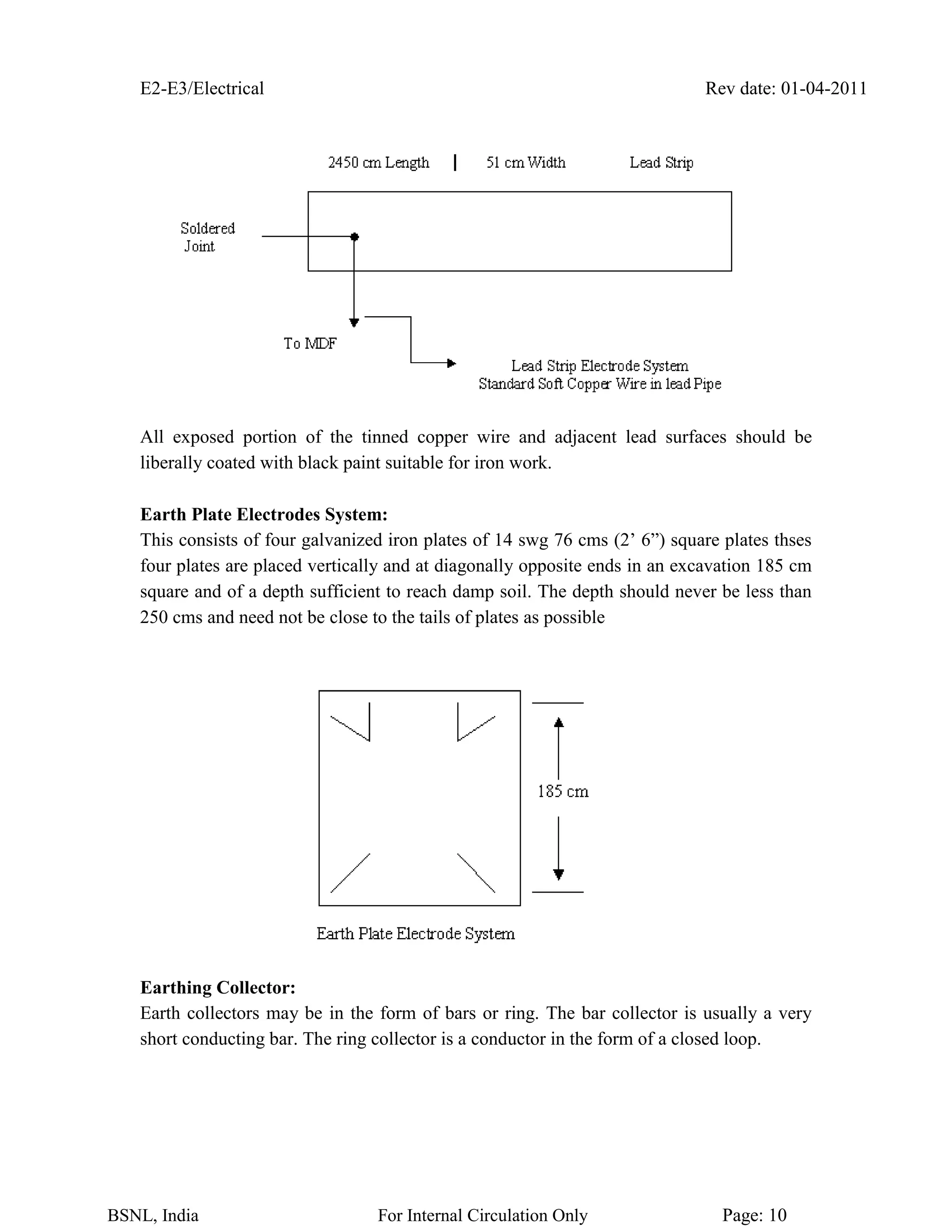
This consists of lead strip 51 mm wide and 6 gms/sq cm buried at a depth of 60 to 90
cms. The strip should preferably laid in one continuous lengths of 2450 cms otherwise
two lengths of 1225 cms should be lain at least 250 cm apart and overlapped by at least
152 mm, the two electrodes being paralleled at the MDF earth bar. The earth lead
protected by a lead pipe should be connected to the lead strip for at least 152 mm by a
plumber wiped joint
E2-E3/Electrical Rev date: 01-04-2011
BSNL, India For Internal Circulation Only Page: 10
All exposed portion of the tinned copper wire and adjacent lead surfaces should be
liberally coated with black paint suitable for iron work.
Earth Plate Electrodes System:
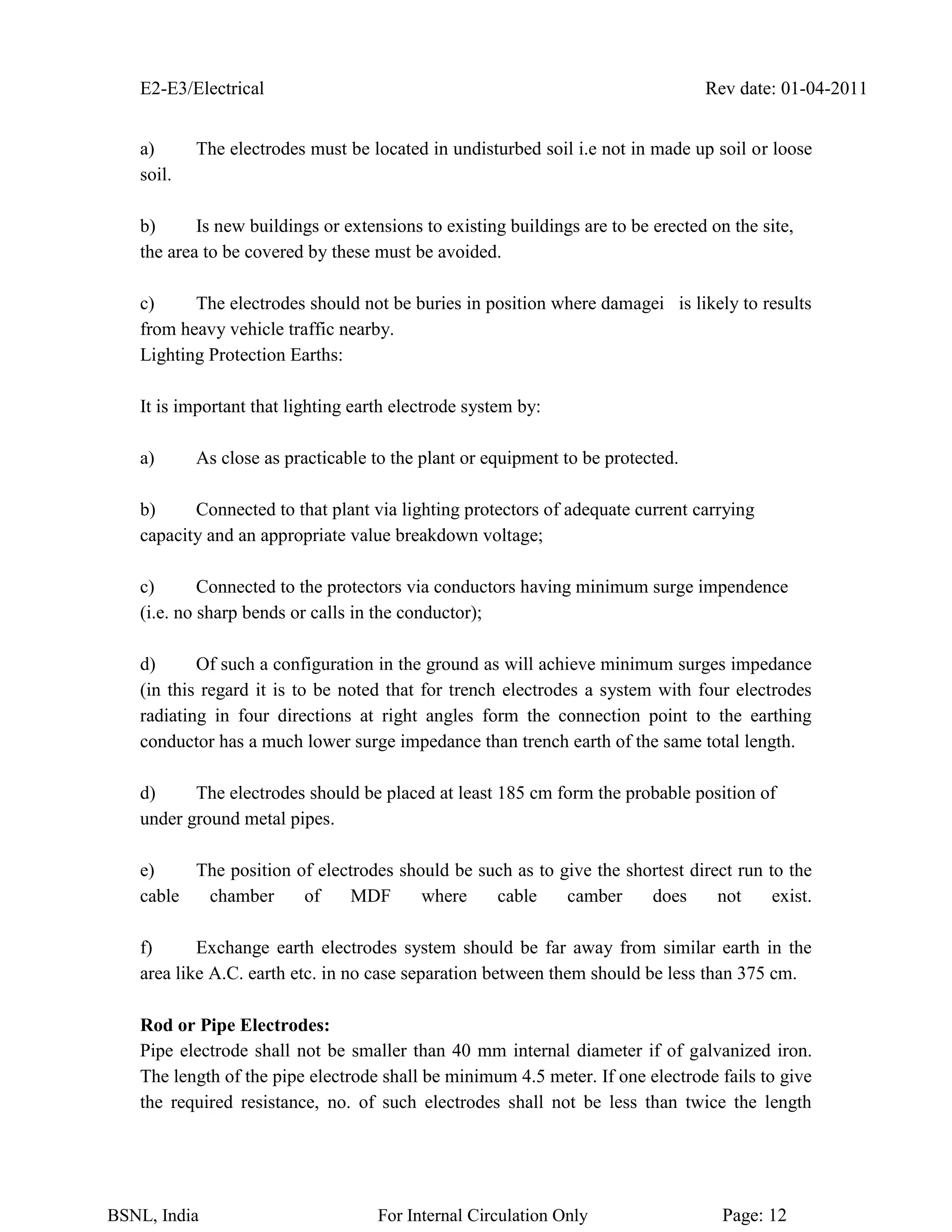
This consists of four galvanized iron plates of 14 swg 76 cms (2’ 6”) square plates thses
four plates are placed vertically and at diagonally opposite ends in an excavation 185 cm
square and of a depth sufficient to reach damp soil. The depth should never be less than
250 cms and need not be close to the tails of plates as possible
Earthing Collector:
Earth collectors may be in the form of bars or ring. The bar collector is usually a very
short conducting bar. The ring collector is a conductor in the form of a closed loop.
E2-E3/Electrical Rev date: 01-04-2011
BSNL, India For Internal Circulation Only Page: 11
The earth collector should be installed above the floor for the cable chamber. The free
space between the collector and the walls should be just sufficient to allow for 60 cm
above the floor. It should allow short are straight connections to cable sheaths and pipes.
Unless the collector acts as a return path to central battery insulated supports should be
made for connections between reinforcement and ring conductor at least every 5m to
10m.
The ring type earth collector is more practical than the bar type because it can be
connected easily and safely with the earth electrode, other buried metal structures the
neutral of electrical network the electrode against lighting over- voltages as well as the
earth distribution systems located in various parts of the buildings.
The ring collector should have as low impedance as possible.
Standards for resistance of earth electrode systems:
The resistance of earth electrode system should be as possible and in any case should not
exceed 2 ohms at any time of the year. In cases where due to local conditions, the
resistance of earth electrode system exceed 2 ohms, two or more similar earth electrode
system should be installed and spaced as far away as possible form each other but not less
than 375 cm from the first electrode system.
The resistance of earth electrode system for electronic system exchange should be less
than 0.5.
Conditions determining the type of earth electrodes systems to be used:
a) Spike earth electrode system is generally used for all new auto exchange
installation where adequate space is available on subsoil suitable for driving the pipes to
the prescribed depth
b) The lead strip electrode system is used when adequate space is available but rock
is encountered at a depth less than 375 cm below ground level.
c) Earth pipe electrode system is used when layout of exchange site is such that
adequate space is not available.
Location of earth electrode:
The following points require careful attention before choosing the site for the earth
electrodes.
E2-E3/Electrical Rev date: 01-04-2011
BSNL, India For Internal Circulation Only Page: 12
a) The electrodes must be located in undisturbed soil i.e not in made up soil or loose
soil.
b) Is new buildings or extensions to existing buildings are to be erected on the site,
the area to be covered by these must be avoided.
c) The electrodes should not be buries in position where damagei is likely to results
from heavy vehicle traffic nearby.
Lighting Protection Earths:
It is important that lighting earth electrode system by:
a) As close as practicable to the plant or equipment to be protected.
b) Connected to that plant via lighting protectors of adequate current carrying
capacity and an appropriate value breakdown voltage;
c) Connected to the protectors via conductors having minimum surge impendence
(i.e. no sharp bends or calls in the conductor);
d) Of such a configuration in the ground as will achieve minimum surges impedance
(in this regard it is to be noted that for trench electrodes a system with four electrodes
radiating in four directions at right angles form the connection point to the earthing
conductor has a much lower surge impedance than trench earth of the same total length.
d) The electrodes should be placed at least 185 cm form the probable position of
under ground metal pipes.
e) The position of electrodes should be such as to give the shortest direct run to the
cable chamber of MDF where cable camber does not exist.
f) Exchange earth electrodes system should be far away from similar earth in the
area like A.C. earth etc. in no case separation between them should be less than 375 cm.
Rod or Pipe Electrodes:
Pipe electrode shall not be smaller than 40 mm internal diameter if of galvanized iron.
The length of the pipe electrode shall be minimum 4.5 meter. If one electrode fails to give
the required resistance, no. of such electrodes shall not be less than twice the length
E2-E3/Electrical Rev date: 01-04-2011
BSNL, India For Internal Circulation Only Page: 13
electrodes. The G.I. Pipe shall be cut tapered at bottom and provided with holes of 12
mm dia drilled not less than 7.5 cm. From each other up to 2 mt Length from bottom.
E2-E3/Electrical Rev date: 01-04-2011
BSNL, India For Internal Circulation Only Page: 14
Questions
1. Why earthing system is required in telecom applications.
2. What are the objectives behind earthing system
3. What are the requirements for effective earthing.
4. Write a short note on classes of earthing system
5. Compare Separate Earths Vs Common Earths.
6. What is Inter System Ground Noise.
7. Write a short note on spike earthing.
8. How the installation of Ring Earth around new telecom departmental building
takes place.
9. What is Earth Plate Electrodes System
10. What are the standards for resistance of earth electrode systems.

More Related Content

Similar to 14A-Earthing.pdf

Tes p-122.10-r0 (1)
Tes p-122.10-r0 (1)Tes p-122.10-r0 (1)
Tes p-122.10-r0 (1)Ibrahim Ali
 
Electrical grounding and earthing
Electrical grounding and earthingElectrical grounding and earthing
Electrical grounding and earthingNitesh Dash
 
Electrical grounding and earthing
Electrical grounding and earthingElectrical grounding and earthing
Electrical grounding and earthingNitesh Dash
 
Earthing and grounding.pptx
Earthing and grounding.pptxEarthing and grounding.pptx
Earthing and grounding.pptxSuhailAbdul2
 
Lightning Protection Considerations for Wired Systems
Lightning Protection Considerations for Wired SystemsLightning Protection Considerations for Wired Systems
Lightning Protection Considerations for Wired SystemsAnalynk Wireless, LLC
 
Importance of Earth Mat in Substation.docx
Importance of Earth Mat in Substation.docxImportance of Earth Mat in Substation.docx
Importance of Earth Mat in Substation.docxvikram desai
 
Electric vechile public charging station presentation by jmv
Electric vechile public charging station presentation  by jmvElectric vechile public charging station presentation  by jmv
Electric vechile public charging station presentation by jmvMahesh Chandra Manav
 
Earthing and grounding
Earthing and groundingEarthing and grounding
Earthing and groundingNilPatel44
 
Earthing Arrangements 17th
Earthing  Arrangements 17thEarthing  Arrangements 17th
Earthing Arrangements 17thPaul Holden
 
earthing -earthing req. relevent codes (1).ppt
earthing -earthing req. relevent codes (1).pptearthing -earthing req. relevent codes (1).ppt
earthing -earthing req. relevent codes (1).pptVikasMore37
 
Electrical grounding and earthing systems
Electrical grounding and earthing systemsElectrical grounding and earthing systems
Electrical grounding and earthing systemsBiswajit Pratihari
 
Nbc2016 and iec information jmv lps
Nbc2016 and iec information jmv lpsNbc2016 and iec information jmv lps
Nbc2016 and iec information jmv lpsMahesh Chandra Manav
 
Presentation department of space by jmv lps
Presentation department of space by jmv lpsPresentation department of space by jmv lps
Presentation department of space by jmv lpsMahesh Chandra Manav
 
Presentation department of space by jmv lps
Presentation department of space by jmv lpsPresentation department of space by jmv lps
Presentation department of space by jmv lpsMahesh Chandra Manav
 
Presentation railtel (railway communication infra company) by jmv lps
Presentation railtel  (railway communication infra company) by jmv lpsPresentation railtel  (railway communication infra company) by jmv lps
Presentation railtel (railway communication infra company) by jmv lpsMahesh Chandra Manav
 

Similar to 14A-Earthing.pdf (20)

Tes p-122.10-r0 (1)
Tes p-122.10-r0 (1)Tes p-122.10-r0 (1)
Tes p-122.10-r0 (1)
 
Electrical grounding and earthing
Electrical grounding and earthingElectrical grounding and earthing
Electrical grounding and earthing
 
Electrical grounding and earthing
Electrical grounding and earthingElectrical grounding and earthing
Electrical grounding and earthing
 
Earthing and grounding.pptx
Earthing and grounding.pptxEarthing and grounding.pptx
Earthing and grounding.pptx
 
Effect of grounding
Effect of groundingEffect of grounding
Effect of grounding
 
Lightning Protection Considerations for Wired Systems
Lightning Protection Considerations for Wired SystemsLightning Protection Considerations for Wired Systems
Lightning Protection Considerations for Wired Systems
 
earthing-system.ppt
earthing-system.pptearthing-system.ppt
earthing-system.ppt
 
Importance of Earth Mat in Substation.docx
Importance of Earth Mat in Substation.docxImportance of Earth Mat in Substation.docx
Importance of Earth Mat in Substation.docx
 
Electric vechile public charging station presentation by jmv
Electric vechile public charging station presentation  by jmvElectric vechile public charging station presentation  by jmv
Electric vechile public charging station presentation by jmv
 
Maintenance free earth electrode
Maintenance free earth electrodeMaintenance free earth electrode
Maintenance free earth electrode
 
EMC and HFPQ for industrial networks - Jos Knockaert, UGent and Peter Thomas...
EMC and HFPQ for industrial networks -  Jos Knockaert, UGent and Peter Thomas...EMC and HFPQ for industrial networks -  Jos Knockaert, UGent and Peter Thomas...
EMC and HFPQ for industrial networks - Jos Knockaert, UGent and Peter Thomas...
 
Earthing and grounding
Earthing and groundingEarthing and grounding
Earthing and grounding
 
Earthing Arrangements 17th
Earthing  Arrangements 17thEarthing  Arrangements 17th
Earthing Arrangements 17th
 
earthing -earthing req. relevent codes (1).ppt
earthing -earthing req. relevent codes (1).pptearthing -earthing req. relevent codes (1).ppt
earthing -earthing req. relevent codes (1).ppt
 
Electrical grounding and earthing systems
Electrical grounding and earthing systemsElectrical grounding and earthing systems
Electrical grounding and earthing systems
 
Nbc2016 and iec information jmv lps
Nbc2016 and iec information jmv lpsNbc2016 and iec information jmv lps
Nbc2016 and iec information jmv lps
 
EMC for Networks - Peter Thomas, Control Specialists and Jos Knockaert, UGent
EMC for Networks - Peter Thomas, Control Specialists and Jos Knockaert, UGentEMC for Networks - Peter Thomas, Control Specialists and Jos Knockaert, UGent
EMC for Networks - Peter Thomas, Control Specialists and Jos Knockaert, UGent
 
Presentation department of space by jmv lps
Presentation department of space by jmv lpsPresentation department of space by jmv lps
Presentation department of space by jmv lps
 
Presentation department of space by jmv lps
Presentation department of space by jmv lpsPresentation department of space by jmv lps
Presentation department of space by jmv lps
 
Presentation railtel (railway communication infra company) by jmv lps
Presentation railtel  (railway communication infra company) by jmv lpsPresentation railtel  (railway communication infra company) by jmv lps
Presentation railtel (railway communication infra company) by jmv lps
 

Recently uploaded

Gfe Mayur Vihar Call Girls Service WhatsApp -> 9999965857 Available 24x7 ^ De...
Gfe Mayur Vihar Call Girls Service WhatsApp -> 9999965857 Available 24x7 ^ De...Gfe Mayur Vihar Call Girls Service WhatsApp -> 9999965857 Available 24x7 ^ De...
Gfe Mayur Vihar Call Girls Service WhatsApp -> 9999965857 Available 24x7 ^ De...srsj9000
 
Gurgaon ✡️9711147426✨Call In girls Gurgaon Sector 51 escort service
Gurgaon ✡️9711147426✨Call In girls Gurgaon Sector 51 escort serviceGurgaon ✡️9711147426✨Call In girls Gurgaon Sector 51 escort service
Gurgaon ✡️9711147426✨Call In girls Gurgaon Sector 51 escort servicejennyeacort
 
SPICE PARK APR2024 ( 6,793 SPICE Models )
SPICE PARK APR2024 ( 6,793 SPICE Models )SPICE PARK APR2024 ( 6,793 SPICE Models )
SPICE PARK APR2024 ( 6,793 SPICE Models )Tsuyoshi Horigome
 
What are the advantages and disadvantages of membrane structures.pptx
What are the advantages and disadvantages of membrane structures.pptxWhat are the advantages and disadvantages of membrane structures.pptx
What are the advantages and disadvantages of membrane structures.pptxwendy cai
 
Biology for Computer Engineers Course Handout.pptx
Biology for Computer Engineers Course Handout.pptxBiology for Computer Engineers Course Handout.pptx
Biology for Computer Engineers Course Handout.pptxDeepakSakkari2
 
Current Transformer Drawing and GTP for MSETCL
Current Transformer Drawing and GTP for MSETCLCurrent Transformer Drawing and GTP for MSETCL
Current Transformer Drawing and GTP for MSETCLDeelipZope
 
HARMONY IN THE HUMAN BEING - Unit-II UHV-2
HARMONY IN THE HUMAN BEING - Unit-II UHV-2HARMONY IN THE HUMAN BEING - Unit-II UHV-2
HARMONY IN THE HUMAN BEING - Unit-II UHV-2RajaP95
 
High Profile Call Girls Nagpur Meera Call 7001035870 Meet With Nagpur Escorts
High Profile Call Girls Nagpur Meera Call 7001035870 Meet With Nagpur EscortsHigh Profile Call Girls Nagpur Meera Call 7001035870 Meet With Nagpur Escorts
High Profile Call Girls Nagpur Meera Call 7001035870 Meet With Nagpur EscortsCall Girls in Nagpur High Profile
 
microprocessor 8085 and its interfacing
microprocessor 8085  and its interfacingmicroprocessor 8085  and its interfacing
microprocessor 8085 and its interfacingjaychoudhary37
 
Study on Air-Water & Water-Water Heat Exchange in a Finned Tube Exchanger
Study on Air-Water & Water-Water Heat Exchange in a Finned Tube ExchangerStudy on Air-Water & Water-Water Heat Exchange in a Finned Tube Exchanger
Study on Air-Water & Water-Water Heat Exchange in a Finned Tube ExchangerAnamika Sarkar
 
(ANVI) Koregaon Park Call Girls Just Call 7001035870 [ Cash on Delivery ] Pun...
(ANVI) Koregaon Park Call Girls Just Call 7001035870 [ Cash on Delivery ] Pun...(ANVI) Koregaon Park Call Girls Just Call 7001035870 [ Cash on Delivery ] Pun...
(ANVI) Koregaon Park Call Girls Just Call 7001035870 [ Cash on Delivery ] Pun...ranjana rawat
 
GDSC ASEB Gen AI study jams presentation
GDSC ASEB Gen AI study jams presentationGDSC ASEB Gen AI study jams presentation
GDSC ASEB Gen AI study jams presentationGDSCAESB
 
High Profile Call Girls Nagpur Isha Call 7001035870 Meet With Nagpur Escorts
High Profile Call Girls Nagpur Isha Call 7001035870 Meet With Nagpur EscortsHigh Profile Call Girls Nagpur Isha Call 7001035870 Meet With Nagpur Escorts
High Profile Call Girls Nagpur Isha Call 7001035870 Meet With Nagpur Escortsranjana rawat
 
Microscopic Analysis of Ceramic Materials.pptx
Microscopic Analysis of Ceramic Materials.pptxMicroscopic Analysis of Ceramic Materials.pptx
Microscopic Analysis of Ceramic Materials.pptxpurnimasatapathy1234
 
Artificial-Intelligence-in-Electronics (K).pptx
Artificial-Intelligence-in-Electronics (K).pptxArtificial-Intelligence-in-Electronics (K).pptx
Artificial-Intelligence-in-Electronics (K).pptxbritheesh05
 
Software and Systems Engineering Standards: Verification and Validation of Sy...
Software and Systems Engineering Standards: Verification and Validation of Sy...Software and Systems Engineering Standards: Verification and Validation of Sy...
Software and Systems Engineering Standards: Verification and Validation of Sy...VICTOR MAESTRE RAMIREZ
 
main PPT.pptx of girls hostel security using rfid
main PPT.pptx of girls hostel security using rfidmain PPT.pptx of girls hostel security using rfid
main PPT.pptx of girls hostel security using rfidNikhilNagaraju
 

Recently uploaded (20)

Gfe Mayur Vihar Call Girls Service WhatsApp -> 9999965857 Available 24x7 ^ De...
Gfe Mayur Vihar Call Girls Service WhatsApp -> 9999965857 Available 24x7 ^ De...Gfe Mayur Vihar Call Girls Service WhatsApp -> 9999965857 Available 24x7 ^ De...
Gfe Mayur Vihar Call Girls Service WhatsApp -> 9999965857 Available 24x7 ^ De...
 
Gurgaon ✡️9711147426✨Call In girls Gurgaon Sector 51 escort service
Gurgaon ✡️9711147426✨Call In girls Gurgaon Sector 51 escort serviceGurgaon ✡️9711147426✨Call In girls Gurgaon Sector 51 escort service
Gurgaon ✡️9711147426✨Call In girls Gurgaon Sector 51 escort service
 
SPICE PARK APR2024 ( 6,793 SPICE Models )
SPICE PARK APR2024 ( 6,793 SPICE Models )SPICE PARK APR2024 ( 6,793 SPICE Models )
SPICE PARK APR2024 ( 6,793 SPICE Models )
 
What are the advantages and disadvantages of membrane structures.pptx
What are the advantages and disadvantages of membrane structures.pptxWhat are the advantages and disadvantages of membrane structures.pptx
What are the advantages and disadvantages of membrane structures.pptx
 
Biology for Computer Engineers Course Handout.pptx
Biology for Computer Engineers Course Handout.pptxBiology for Computer Engineers Course Handout.pptx
Biology for Computer Engineers Course Handout.pptx
 
Current Transformer Drawing and GTP for MSETCL
Current Transformer Drawing and GTP for MSETCLCurrent Transformer Drawing and GTP for MSETCL
Current Transformer Drawing and GTP for MSETCL
 
HARMONY IN THE HUMAN BEING - Unit-II UHV-2
HARMONY IN THE HUMAN BEING - Unit-II UHV-2HARMONY IN THE HUMAN BEING - Unit-II UHV-2
HARMONY IN THE HUMAN BEING - Unit-II UHV-2
 
High Profile Call Girls Nagpur Meera Call 7001035870 Meet With Nagpur Escorts
High Profile Call Girls Nagpur Meera Call 7001035870 Meet With Nagpur EscortsHigh Profile Call Girls Nagpur Meera Call 7001035870 Meet With Nagpur Escorts
High Profile Call Girls Nagpur Meera Call 7001035870 Meet With Nagpur Escorts
 
microprocessor 8085 and its interfacing
microprocessor 8085  and its interfacingmicroprocessor 8085  and its interfacing
microprocessor 8085 and its interfacing
 
Study on Air-Water & Water-Water Heat Exchange in a Finned Tube Exchanger
Study on Air-Water & Water-Water Heat Exchange in a Finned Tube ExchangerStudy on Air-Water & Water-Water Heat Exchange in a Finned Tube Exchanger
Study on Air-Water & Water-Water Heat Exchange in a Finned Tube Exchanger
 
young call girls in Rajiv Chowk🔝 9953056974 🔝 Delhi escort Service
young call girls in Rajiv Chowk🔝 9953056974 🔝 Delhi escort Serviceyoung call girls in Rajiv Chowk🔝 9953056974 🔝 Delhi escort Service
young call girls in Rajiv Chowk🔝 9953056974 🔝 Delhi escort Service
 
(ANVI) Koregaon Park Call Girls Just Call 7001035870 [ Cash on Delivery ] Pun...
(ANVI) Koregaon Park Call Girls Just Call 7001035870 [ Cash on Delivery ] Pun...(ANVI) Koregaon Park Call Girls Just Call 7001035870 [ Cash on Delivery ] Pun...
(ANVI) Koregaon Park Call Girls Just Call 7001035870 [ Cash on Delivery ] Pun...
 
GDSC ASEB Gen AI study jams presentation
GDSC ASEB Gen AI study jams presentationGDSC ASEB Gen AI study jams presentation
GDSC ASEB Gen AI study jams presentation
 
High Profile Call Girls Nagpur Isha Call 7001035870 Meet With Nagpur Escorts
High Profile Call Girls Nagpur Isha Call 7001035870 Meet With Nagpur EscortsHigh Profile Call Girls Nagpur Isha Call 7001035870 Meet With Nagpur Escorts
High Profile Call Girls Nagpur Isha Call 7001035870 Meet With Nagpur Escorts
 
Microscopic Analysis of Ceramic Materials.pptx
Microscopic Analysis of Ceramic Materials.pptxMicroscopic Analysis of Ceramic Materials.pptx
Microscopic Analysis of Ceramic Materials.pptx
 
★ CALL US 9953330565 ( HOT Young Call Girls In Badarpur delhi NCR
★ CALL US 9953330565 ( HOT Young Call Girls In Badarpur delhi NCR★ CALL US 9953330565 ( HOT Young Call Girls In Badarpur delhi NCR
★ CALL US 9953330565 ( HOT Young Call Girls In Badarpur delhi NCR
 
Artificial-Intelligence-in-Electronics (K).pptx
Artificial-Intelligence-in-Electronics (K).pptxArtificial-Intelligence-in-Electronics (K).pptx
Artificial-Intelligence-in-Electronics (K).pptx
 
Software and Systems Engineering Standards: Verification and Validation of Sy...
Software and Systems Engineering Standards: Verification and Validation of Sy...Software and Systems Engineering Standards: Verification and Validation of Sy...
Software and Systems Engineering Standards: Verification and Validation of Sy...
 
main PPT.pptx of girls hostel security using rfid
main PPT.pptx of girls hostel security using rfidmain PPT.pptx of girls hostel security using rfid
main PPT.pptx of girls hostel security using rfid
 
🔝9953056974🔝!!-YOUNG call girls in Rajendra Nagar Escort rvice Shot 2000 nigh...
🔝9953056974🔝!!-YOUNG call girls in Rajendra Nagar Escort rvice Shot 2000 nigh...🔝9953056974🔝!!-YOUNG call girls in Rajendra Nagar Escort rvice Shot 2000 nigh...
🔝9953056974🔝!!-YOUNG call girls in Rajendra Nagar Escort rvice Shot 2000 nigh...
 

14A-Earthing.pdf

  • 1. E2-E3/Electrical Rev date: 01-04-2011 BSNL, India For Internal Circulation Only Page: 1 E2-E3: ELECTRICAL CHAPTER-16 EARTHING
  • 2. E2-E3/Electrical Rev date: 01-04-2011 BSNL, India For Internal Circulation Only Page: 2 Earthing Introduction: Earthing is an essential part of any electric /electronic system. Utmost care is required to be taken for provision of proper and effective Earthing for various telecom installations. This chapter discusses about various types of Earthing, which are used in Telecom Installations. Objective: After the end of this chapter, the participants would be able to know: Objective of Earthing Requirement of effective Earthing Various types of earthing used in telecom installations Objective of Earthing System: The objective of Earthing system may be summarized as follows:- a) Reduction of Crosstalk and Noise:- On pole of the battery (+Ve pole) is earthed in the telephone exchange so that cross talk between the various circuits due to the speech currents of one circuit finding path through the other via common battery feed points of the transmission bridge and reduced NSN via earthed terminal of the battery. b) Earth is used to afford convenience & “reliability, in the operate path of the ircuits involved in the switching apparatus of telecom circuits. c) Used as return path for the conductor in some telegraph and voice circuits. d) Protection of costly apparatus and persons against foreign voltages and leakage currents from power wirings to the metallic frame of the equipment. e) Protection of buildings and equipments from lighting strikes. f) Earthing power supply systems is used to effect reliability of power as it helps to provide stability of voltage conditions preventing excess fluctuations and providing a measure of protection against lighting.
  • 3. E2-E3/Electrical Rev date: 01-04-2011 BSNL, India For Internal Circulation Only Page: 3 g) To divert stray RF energy from sensitive audio, video control and computer equipments. Requirements for Effective Earthing: An earthing system must meet the following specifications :- 1. The resistance to the earth must be within allowable limit for the particular application. 2. The electrode buried in ground must be : a) Having good electrical conductivity to carry highest specified load current . b) Immune to the corrosive action of the soil all along the period . c) Of sufficient mechanical strength to enable them to be installed without any damage . d) Inert i.e. must not be a source of galvanic corrosion current within the system to be protected. 3. The earth electrode must provide as much as area of contact as possible with the soil to reduce the resistance of the current path to the earth. 4. The resistance of the earth connection must remain within the allowable specified limit throughout the session Classes of Earthing systems: Eathing systems are provided to serve many different purposes. They may be divided in two major categories, viz a) Service Earthing systems b) Protective Earthing System a) Service Earthing systems:- Equipment earthing for switching , transmission ,measuring equipments etc. b) Protective Earthing System:- i. Power system earth to provide protection against excessive current. ii. Lighting protective earth to provide protection against excessive voltage. Requirements for Service Earthing System: In general, service earthing system should have a low D.C. resistance to the general body of the earth. In order to ensure that the potential drop across the earth connection is low. If any current flows through the service earthing system, a potential difference will be
  • 4. E2-E3/Electrical Rev date: 01-04-2011 BSNL, India For Internal Circulation Only Page: 4 developed across the earth connection. This can introduce interference in the form of electrical noise into any telecommunication circuit connected to that earthing system. The value of resistance which must be met by a service earthing will depend on the purposes for which the earth likely to be carried by the earthing system, and the tolerable voltage drop across the earth connection. Requirements for protective Earthing System: The Requirements to be satisfied by a protective earthing system are governed by the purpose for which the earth is being provided earths which protect against excessive current (e.g. power supply protective earth) must have low resistance in order to: a) Carry the anticipated value of over current without overheating and “burning out” b) Enable sufficient current flow to ground to ensure that any over current disconnected the current after a very short time. c) Prevent hazardous potential differences to develop across the earth connection, Excessive potential differences can cause breakdown of insulation, and danger to life and limb). The foregoing requirements can be satisfied by heavy gauge conductors of very low resistance connected to earthing systems of very low resistance (typically les than on ohm) d) Able to withstand indefinitely the corrosive action of soil e) Inert in relation to the system to be protected (i.e must not be a source of galvanic corrosion currents) f) The resistance of the earth connection must remain reasonably constant throughout the various seasons of the year. g) Earths which protect against excessive voltage (e.g. earths connected to lighting protection systems) must posses a low surge impedance in order to enable the lighting surge currents to be easily conveyed to the earth and thus diverted away from the equipment which is to be protected form the lighting. Separate Earths Vs common Earth:
  • 5. E2-E3/Electrical Rev date: 01-04-2011 BSNL, India For Internal Circulation Only Page: 5 Attempts to provide separate earthing system for different purposes at a common location have generally proved to be unsatisfactory for the following reasons: a) In practice it usually not possible to ensure that there is no electrical coupling between separate earthing systems in close proximity. This is because of casual and uncontrolled interconnections with in the installation, and also because of galvanic coupling in the ground b) There is a risk of fire, and a risk of danger to human life, because a difference in potential between various earths might cause excessive current and/or excessive voltage. c) Currents may flow through the structure or between various earthing systems and cause corrosion. On the other hand separate earths have in the post been thought desirable for certain categories of service earth. This has usually been done an attempt to eliminate noise from the telecommunication circuits. Most authorities now consider that it is for battery not to try to provide separate earthing systems, but to provide a common Earthing system at an installation, and to design and install it in such a way that it satisfies the requirements of the various earthing systems which are required at that installation. If the ground resistively near an installation is high, it may be necessary to provide part of the earth electrode installation at some distance away where the ground resistivity is better. In such cases an earth electrode system close the building should be provided for lighting protection and this should be interconnected with the remote electrode system The main advantage of a common earthing system are:- a) By care fully bonding the various earthing systems together, the potential difference between on earth connection and another is negligible. Thus no excessive current or voltages will be developed within the earthing system. Safety grounding & Inter system Ground Noise: A computer equipment is equipped with three wire grounding type AC power connectors. Many type of equipment, such as lamps, have only two wire type plugs since two wires are all that is necessary to deliver AC power, the third wire is a safety ground wire, which is connected to all exposed exterior metal parts on the computer equipment the grounding connection provided at the wall receptacle is connected within the building to copper
  • 6. E2-E3/Electrical Rev date: 01-04-2011 BSNL, India For Internal Circulation Only Page: 6 water popes and/or structural metal parts of the building. The purpose of this arrangement is to protect the user form electrical shock when the exposed metal parts of a faulty computer and building structural metal parts are touched. For safety exposed devices such as RS-232 connectors and printer ports are considered to be exposed metal parts. For this reason, the voltage at any connector pin must be ground or present a small voltage with respect to ground. The result is that in virtually all computer equipment, the CPU common wire or ground reference is connected to the safety grounding wire (and the enclosure) of the equipment. In the system including equipment that is arrangement leads to a conflict. Every interconnect device has two connections, which are attempting to establish the common reference voltage for date communications: 1. The common wire in the date line, which connects the device to other equipment 2. The device’s safety grounding wire The situation is sometime knows as a “ground loop”. The existence of the loop can lead to differences between the common reference voltage between any interconnected devices must not be confused with other power problems such as common mode noise, normal mode noise, EMI, or RFI. These ground voltage differences are referred to as INTER-SYSTEM GROUND NOISE. Design Principles for Earthing System: Earthing systems should be designed to achieve the following:- a) Adequate current capacity (DC or AC as appropriate) b) Adequate mechanical strength to withstand the rigours of service without fracturing. c) In the case of lighting protective earths adequate-surge-current carrying ability. Installation of Ring Earth around new telecom departmental building: A trench, 30 cms wide and normally 150 cms deep is dug. The depth should be 1-1.5 mt. In case of rocky area the depth may be 60-90 cms. GI strip of size 50 x 3 mm is laid in the trench. The joints are properly wrapped and sealed by waterproof tape.
  • 7. E2-E3/Electrical Rev date: 01-04-2011 BSNL, India For Internal Circulation Only Page: 7 In case of new building ring earth should act as the equipotential bonding and all earthing equipments are to be extended from the ring earth Where is difficult to lay ring earth such as private/ rented building due to space constants the plate/ spike earth may be used. Telephone Exchange:- The main requirements of the earthing system at a telephone system at a telephone exchange are: a) To provide a low resistance path of ground. b) To be able discharge the maximum anticipated current which the earth system as expected to carry, both under working conditions and under fault conditions. Earthing of antenna Towers mounted on top of building For earthing of tower on top of a building, 50 x3 GI Strip down lead should be bonded to any two opposite tower legs and brought down along out side of the building and connected to the ring earth. Earthing of Waveguides: The wave guide for UHF/VHF which are aluminum and that for mico wave system which are proper wave guide are mounted on the tower and connected to antenna. all such wave guide should be individually earth ed at the top and at bottom of the tower and at in – between intervals by earthing kits as recommended by the manufacture Service Earths: Service earth which carry current (e.g.teleprinter earths which may carry 20- 25 mA) must be capable of surviving the discharge of such current to ground for their flowing through a steel earth electrode . Earth electrode Materials: Since copper is a good electrical conductor,t here is a great temptation to use copper as the material; for earth electrodes, e.g. bare copper wire copper plates, copper-clad steel rods, etc. However, due to the position of copper in the electrochemical series it rapidly causes correction of steel, Zinc lead aluminum etc. thus the use of copper as an earthing
  • 8. E2-E3/Electrical Rev date: 01-04-2011 BSNL, India For Internal Circulation Only Page: 8 material requires very careful attention to the prevention of corrosion and it is usually better to chooses some other metal e.g. galvanized steel, plain steel stainless steel etc. Spike Earth : Spike electrodes consist of mental rods or pipes driven vertically into the ground copper, stainless steel and mild steel are the most suitable material being corrosion resistant used a as rod electrodes. The present system consist of twenty 25 mm or 38 mm diameter Gl pipes each of 275 or 375 cm length. Each pipe is used as an earth spike, driven to its full length into the ground, the spacing between any two being not less than 375 cm. no case it should be less than 250 cm. This spacing between adjacent electrodes ahs a significant influence on the potential distribution over the earth around the electrodes ahs a significant influence on the potential distribution over the earth around the electrodes system the condition of minimum resistance to earth in a multiple earth system, require that this spacing should be as large as possible. In practice, spacing of 375 is found adequate. Depending upon the soil resistivity of particular place. The number and length of spike can be worked out to achieve the desired value of earth resistance. The position for the spike should be marked out on site and trench should be excavated to take the bending cable which will be used to connect all the spikes in parallel for leading into premises. The trench should be about 45 cms deep. The spikes should be driven
  • 9. E2-E3/Electrical Rev date: 01-04-2011 BSNL, India For Internal Circulation Only Page: 9 vertically into the trench until the top of the driving head is 30 cms above the bottom of the excavation. A driving head or suitable size bolt is supplied with each spike and this must be used to prevent the top of the spike being damaged during driving operation. When spikes has been driven fully into the ground. It will probably be found that the driving head will be a tight fit on the spike and in these circumstances it may be left in positioning no factor attempts being made to remove it. The spike should be connected together by a continuous main earth lead, nominally of size 19/0.64” bare tinned copper, protected by a lead pipe to prevent corrosion. The lead pipe containing the earth lead should be lightly dressed down and wiped on to the bare tinned copper conductor at each side of binder. The binder should be soft copper wire 0.056” diameter, would round the earth lead at the point where it is held in the clamp on the spike. The lead pipe used should be 19 mm nominal diameter and 10 kg. Per 460 cms length in weight. All exposed portion should be coated with black paint suitable for iron work. The binder and exposed part of the earth lead should be thoroughly tinned. The earth lead should be clamped at the point as low as possible on the spike and bent so as to lie along the bottom of the trench. The main earth lead should run as straight and short as possible from the electrode system to the earth bar on the MDF via earth bar in the cable chamber without breaking its continuity by joints. From MDF a separate lead of 19/.064” bare tinned copper should be run along the shortest route and terminated on the earth bar of exchange D.C/ distribution board. Lead strip electrode system: This consists of lead strip 51 mm wide and 6 gms/sq cm buried at a depth of 60 to 90 cms. The strip should preferably laid in one continuous lengths of 2450 cms otherwise two lengths of 1225 cms should be lain at least 250 cm apart and overlapped by at least 152 mm, the two electrodes being paralleled at the MDF earth bar. The earth lead protected by a lead pipe should be connected to the lead strip for at least 152 mm by a plumber wiped joint
  • 10. E2-E3/Electrical Rev date: 01-04-2011 BSNL, India For Internal Circulation Only Page: 10 All exposed portion of the tinned copper wire and adjacent lead surfaces should be liberally coated with black paint suitable for iron work. Earth Plate Electrodes System: This consists of four galvanized iron plates of 14 swg 76 cms (2’ 6”) square plates thses four plates are placed vertically and at diagonally opposite ends in an excavation 185 cm square and of a depth sufficient to reach damp soil. The depth should never be less than 250 cms and need not be close to the tails of plates as possible Earthing Collector: Earth collectors may be in the form of bars or ring. The bar collector is usually a very short conducting bar. The ring collector is a conductor in the form of a closed loop.
  • 11. E2-E3/Electrical Rev date: 01-04-2011 BSNL, India For Internal Circulation Only Page: 11 The earth collector should be installed above the floor for the cable chamber. The free space between the collector and the walls should be just sufficient to allow for 60 cm above the floor. It should allow short are straight connections to cable sheaths and pipes. Unless the collector acts as a return path to central battery insulated supports should be made for connections between reinforcement and ring conductor at least every 5m to 10m. The ring type earth collector is more practical than the bar type because it can be connected easily and safely with the earth electrode, other buried metal structures the neutral of electrical network the electrode against lighting over- voltages as well as the earth distribution systems located in various parts of the buildings. The ring collector should have as low impedance as possible. Standards for resistance of earth electrode systems: The resistance of earth electrode system should be as possible and in any case should not exceed 2 ohms at any time of the year. In cases where due to local conditions, the resistance of earth electrode system exceed 2 ohms, two or more similar earth electrode system should be installed and spaced as far away as possible form each other but not less than 375 cm from the first electrode system. The resistance of earth electrode system for electronic system exchange should be less than 0.5. Conditions determining the type of earth electrodes systems to be used: a) Spike earth electrode system is generally used for all new auto exchange installation where adequate space is available on subsoil suitable for driving the pipes to the prescribed depth b) The lead strip electrode system is used when adequate space is available but rock is encountered at a depth less than 375 cm below ground level. c) Earth pipe electrode system is used when layout of exchange site is such that adequate space is not available. Location of earth electrode: The following points require careful attention before choosing the site for the earth electrodes.
  • 12. E2-E3/Electrical Rev date: 01-04-2011 BSNL, India For Internal Circulation Only Page: 12 a) The electrodes must be located in undisturbed soil i.e not in made up soil or loose soil. b) Is new buildings or extensions to existing buildings are to be erected on the site, the area to be covered by these must be avoided. c) The electrodes should not be buries in position where damagei is likely to results from heavy vehicle traffic nearby. Lighting Protection Earths: It is important that lighting earth electrode system by: a) As close as practicable to the plant or equipment to be protected. b) Connected to that plant via lighting protectors of adequate current carrying capacity and an appropriate value breakdown voltage; c) Connected to the protectors via conductors having minimum surge impendence (i.e. no sharp bends or calls in the conductor); d) Of such a configuration in the ground as will achieve minimum surges impedance (in this regard it is to be noted that for trench electrodes a system with four electrodes radiating in four directions at right angles form the connection point to the earthing conductor has a much lower surge impedance than trench earth of the same total length. d) The electrodes should be placed at least 185 cm form the probable position of under ground metal pipes. e) The position of electrodes should be such as to give the shortest direct run to the cable chamber of MDF where cable camber does not exist. f) Exchange earth electrodes system should be far away from similar earth in the area like A.C. earth etc. in no case separation between them should be less than 375 cm. Rod or Pipe Electrodes: Pipe electrode shall not be smaller than 40 mm internal diameter if of galvanized iron. The length of the pipe electrode shall be minimum 4.5 meter. If one electrode fails to give the required resistance, no. of such electrodes shall not be less than twice the length
  • 13. E2-E3/Electrical Rev date: 01-04-2011 BSNL, India For Internal Circulation Only Page: 13 electrodes. The G.I. Pipe shall be cut tapered at bottom and provided with holes of 12 mm dia drilled not less than 7.5 cm. From each other up to 2 mt Length from bottom.
  • 14. E2-E3/Electrical Rev date: 01-04-2011 BSNL, India For Internal Circulation Only Page: 14 Questions 1. Why earthing system is required in telecom applications. 2. What are the objectives behind earthing system 3. What are the requirements for effective earthing. 4. Write a short note on classes of earthing system 5. Compare Separate Earths Vs Common Earths. 6. What is Inter System Ground Noise. 7. Write a short note on spike earthing. 8. How the installation of Ring Earth around new telecom departmental building takes place. 9. What is Earth Plate Electrodes System 10. What are the standards for resistance of earth electrode systems.