
Recommended
Recommended
More Related Content
What's hot
What's hot (20)
Viewers also liked
Viewers also liked (20)
Recently uploaded
Recently uploaded (20)
100510 mpm blasthole_sampling_experiments
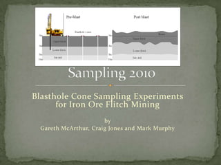
- 1. Blasthole Cone Sampling Experiments for Iron Ore Flitch Mining by Gareth McArthur, Craig Jones and Mark Murphy
- 2. Thanks to : Rio Tinto Gareth McArthur and Craig Jones Mine teams at Mesa A and Mesa K
- 3. Blasthole? Blasthole cone? Flitch mining?
- 12. Assumptions for flitch mining Methods of sampling
- 13. 2 (40%) 2 (40%) 2 (20%)
- 14. 1. Identify two high points 2. Cut to slots, A and B 3. Sample increments from faces using the 2:2:1 rule 4. Reject the sub drill increment 5. Combine the respective flitch increments from the A and B slots into the final samples
- 15. Process Hole depth versus sampling face cone height Variation in cones heights/shapes Painting the cones to mark sampling intervals
- 16. 1. 2. 3. 4. 5. 6. 7. Test the blasthole rig at Mesa J destined for Mesa A Track the actual depths drilled sampling interfaces Paint the cone at the sampling interfaces Collect samples using the 2:2:1 rule on cone face Measure actual sampling interfaces heights using paint Collect second samples using reference paint marks Compare the results
- 21. Depths to sampling boundaries Sampling intervals in cone faces Comparison of blind (2:2:1) to painted sampling intervals
- 22. Plot shows the drill rod measurements of end of flitch – driller estimation error
- 27. Ratio of material report to blast cone is highly variable Sub-drill is often over represented in the cone by a small fraction Flitch samples in the cone are on average equal proportions but with high variation from hole to hole Despite noise and difference between paint-marked actual and 2:2:1 estimated sample intervals grades are similar (albeit noisy) when compared. Paint markings of boundaries should improve precision. More detail in AusIMM Publication SAMPLING CONFERENCE / PERTH, WA, 11 - 12 MAY 2010, p 131 to136.
Editor's Notes
- IntroductionThank you This is a story about some sampling experiments by mine geologists who where interested in the validity of blast hole sampling
- Question: Who in the audience has seen a blast hole coneMovie showing rig – collaring of the blasthole]Point outThis is a blasthole rigNote the flaps to reduce flying fragmentsNoteDust losses initially (and safety issues)Flaps somewhat successfulDust settles after some depth reached
- Main pointsNote paint to show cone shaped after some drillingNote cone shape is irregular
- Flitch miningImage left show conceptual before blasting for flitch mining, right shows after blasting and heaveFlitch woodworking terms meaning planks of the same log or beamMining several layers from the one blast (usual case is two)Note ‘sub drill’ required to get a level floor on the lower flitchIdeally would like to sample each layer independentlyIn some cases the upper flitch may be waste over oreDeeper may be ore over waste
- Mesa A (Warramboo)About 200 km south west of Dampier in WA, near the north-west cost highway in Australia JV between Rio Tinto (53%) and RobeMost recent channel iron deposit (CID) developed with first ore shipped in March this yearInitial production of 20 Mt/a increasing to 25 Mt/a, high grade reserves almost 250 MtReplacing waning production from the Mesa J and Mesa K deposits
- Schematic geology at Mesa A (some vertical exaggeration)Channel iron deposit for Tertiary age (40 My)Sub horizontal layers of iron pisolites in a goethite matrix – grading around 55-58% FeFS study conditional simulation work indicated that :A grade control process is needed for miningThe mining bench height for optimal resource recovery should be 4 m
- View of the Mesa A ‘Portal’
- Shows annotated geology- Note ore boundaries are undulate- The TP zone is about 5 m to 15 thick – lower bench 5 m between 78 and 83 RL- Flitch mining will recover more ore from the TP
- The general rule of thumb is that for a given hole depth the ratio of upper to lower flitch to sub drill is 2 :2 :2Cone face cut with a shovel and samplers reject top fifth of sample height Two equal sample intervals representing upper and lower flitch samplesNote usual practice if not to have paint makers majority of sampling there are no paint markers as shown in this image
- Image shows relationship between blasthole total depth (including sub drill) and cone height Note two different areas tested (one holes around 10 m, the other around 14 m)Very large range of cone heights but generally height in cm = depth x 3.5Interpretation – there seems to be an expected cone height related to depth by highly variables
- Plot shows the drill rod measurements of depth to samplingNote sorted so hole depth increases to the rightY-axis is the proportion of the drillhole depth assigned to upper, lower flitch and sub drillY-axis two shows the average for all 126 holesQuestion : If rigs were fitted with an automatic painting system does the driller correctly identify the sampling interfaces?ObservationsShorter holes tend to have sampling interfaces a little shortLonger holes tend to have sampling interfaces a little longOn average the results follow the 2:2:1 rule within a few percent.If there was an automatic painting system then the driller would do a reasonable job of identifying the sampling interfaces
- This plots similar theme to last but showing the proportion of each sampling layer in blast hole cones (A faces)Note high holes sorted in depth to the rightNote trend to getting more upper flitch samples in deeper holes, and less sub drillOverall the 2:2:1 expected ratio more like 3.5:3.5:3.0Conclusions: Paint marks would significantly improve identifying the layers be sampled.
- Comparison of 10 chemical assays for (38 blasthole cones) from the upper flitchIron, LOI, silica, alumina and phosphorous the key itemsObservationsDespite delimitation errors in the 2:2:1 samples the results though scattered are generally unbiasedMost regression slopes (through origin) are 0.95 to 1.05The sample difference is comparable to the spatial nugget effect for these types of deposit
- Chemical comparisons for the lower flitchSimilar conclusions to the upper flitch – noisy but no significant biases
- Flitch sampling is problematic for blast hole samplingCan’t assume the ratio of layers to be sampled in the blasthole related to the ratios in the blasthole cone.A painting system to mark the flitch and sub drill boundaries would assist in local accuracy.Despite delimitation errors in the cone sampling comparative assay results show that the results of ‘blind’ cone flitch sampling may still be acceptable for global grade control estimates.Has the flitch sampling been a waste of time? These results show the results are noisy but generally acceptable for grade control purposes.
- SAMPLING CONFERENCE / PERTH, WA, 11 - 12 MAY 2010