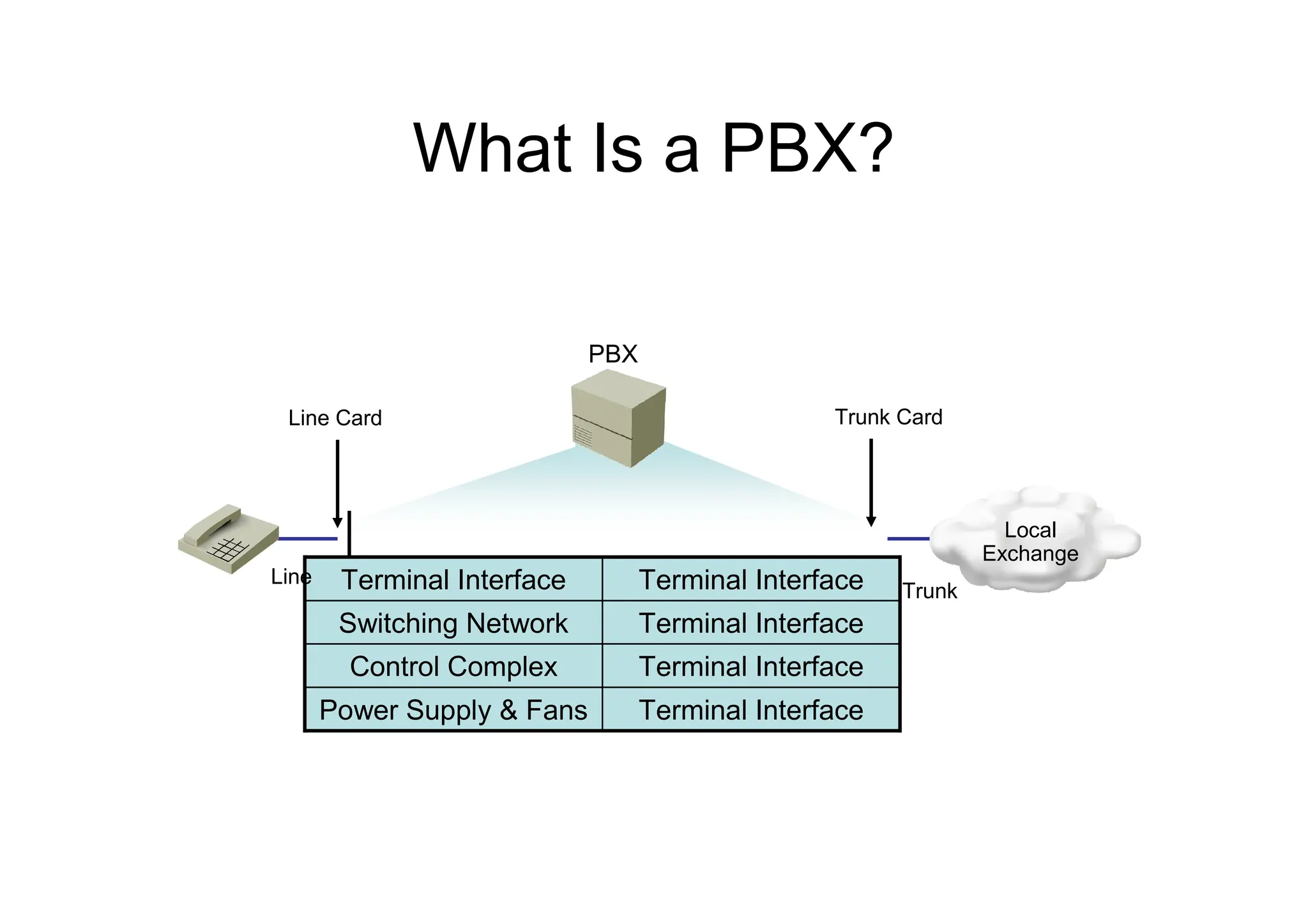
What Is aPBX?
PBX
Terminal Interface
Power Supply & Fans
Terminal Interface
Control Complex
Terminal Interface
Switching Network
Terminal Interface
Terminal Interface
Line Card Trunk Card
Line
Trunk
Local
Exchange
5.
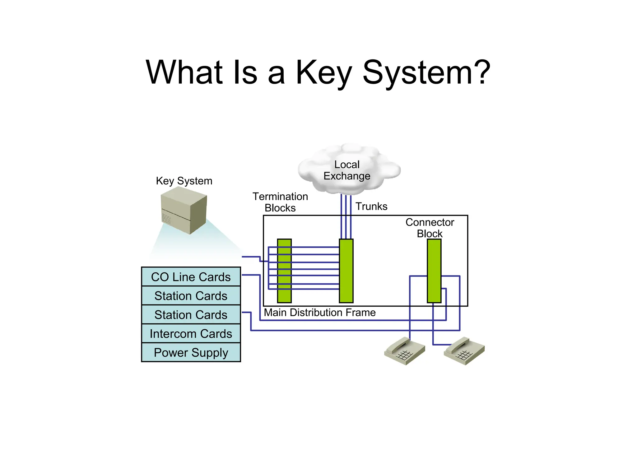
What Is aKey System?
Key System
Termination
Blocks
Connector
Block
Trunks
Main Distribution Frame
Power Supply
Intercom Cards
Station Cards
Station Cards
CO Line Cards
Local
Exchange
6.
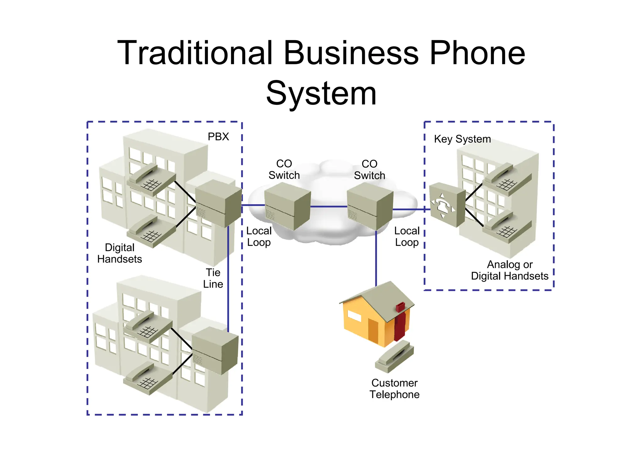
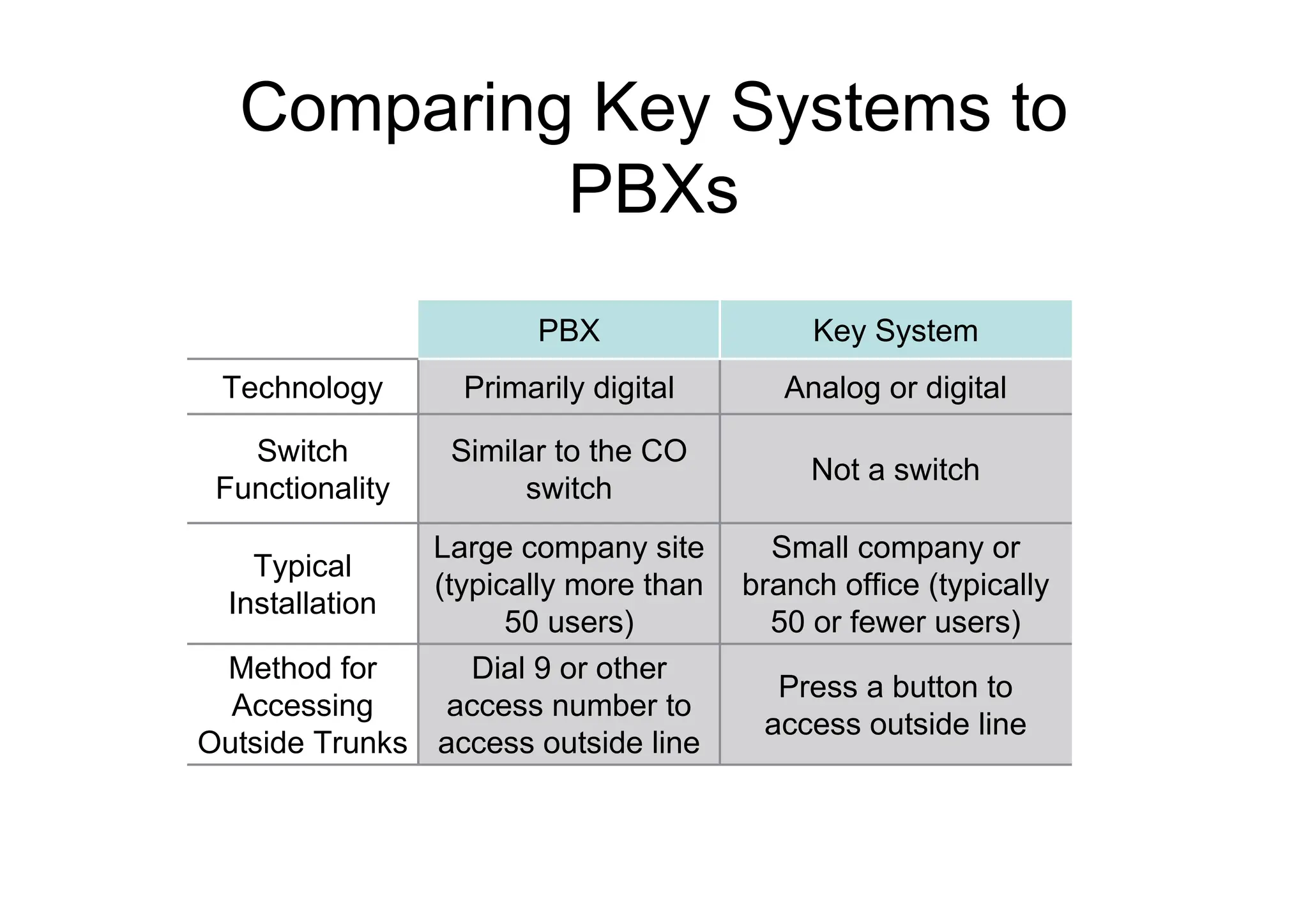
Comparing Key Systemsto
PBXs
Press a button to
access outside line
Dial 9 or other
access number to
access outside line
Method for
Accessing
Outside Trunks
Small company or
branch office (typically
50 or fewer users)
Large company site
(typically more than
50 users)
Typical
Installation
Not a switch
Similar to the CO
switch
Switch
Functionality
Analog or digital
Primarily digital
Technology
Key System
PBX
7.
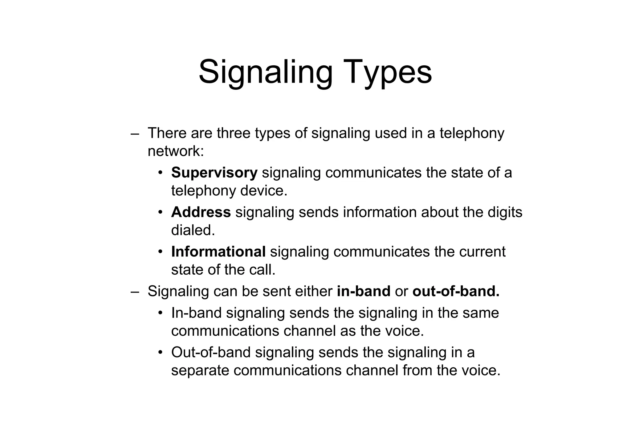
Signaling Types
– Thereare three types of signaling used in a telephony
network:
• Supervisory signaling communicates the state of a
telephony device.
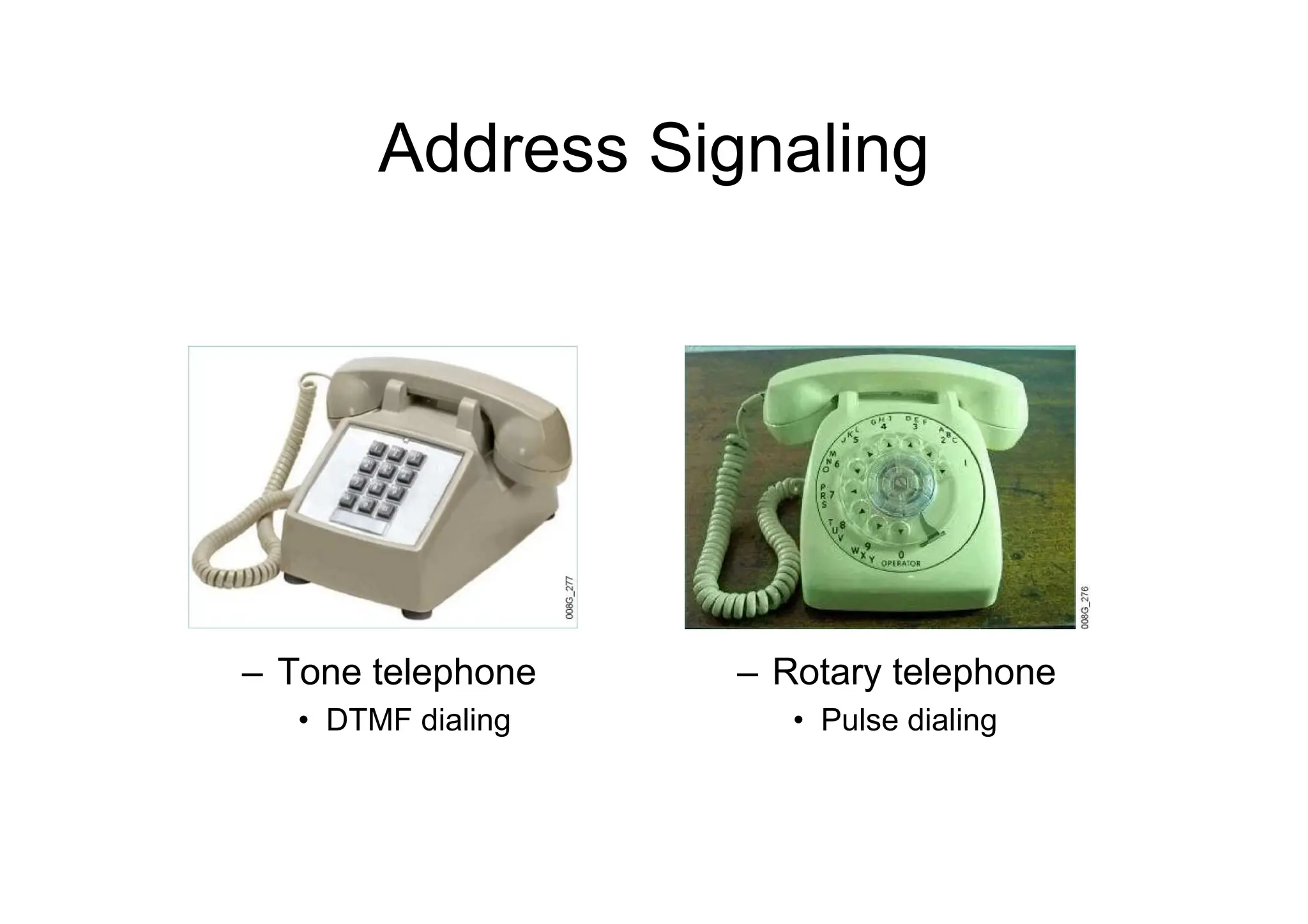
• Address signaling sends information about the digits
dialed.
• Informational signaling communicates the current
state of the call.
– Signaling can be sent either in-band or out-of-band.
• In-band signaling sends the signaling in the same
communications channel as the voice.
• Out-of-band signaling sends the signaling in a
separate communications channel from the voice.
8.
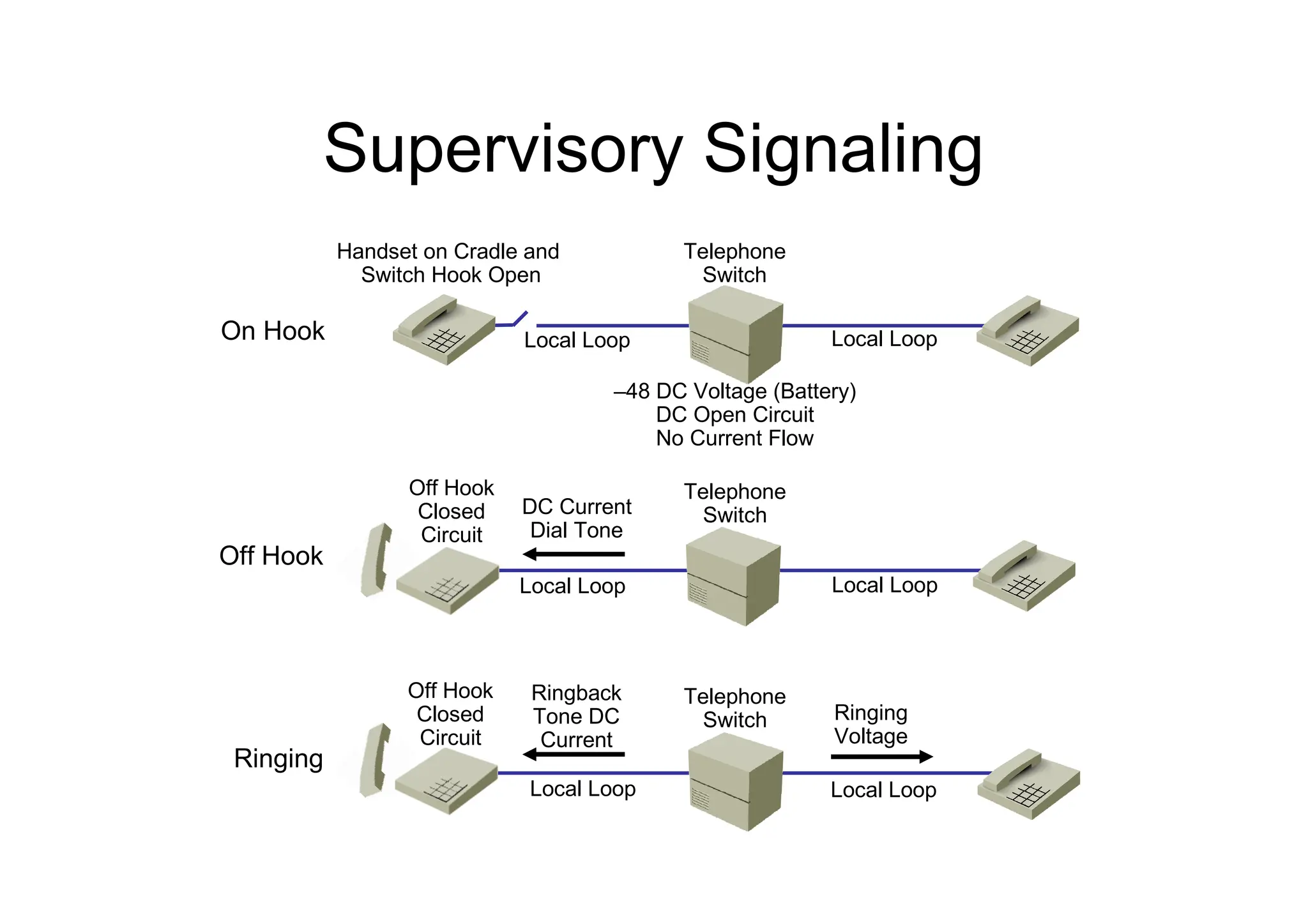
Supervisory Signaling
On Hook
OffHook
Ringing
Handset on Cradle and
Switch Hook Open
Telephone
Switch
Telephone
Switch
Telephone
Switch
Local Loop
Local Loop
Local Loop
Local Loop
Local Loop
Local Loop
DC Current
Dial Tone
Ringback
Tone DC
Current
Off Hook
Closed
Circuit
Off Hook
Closed
Circuit
Ringing
Voltage
–48 DC Voltage (Battery)
DC Open Circuit
No Current Flow
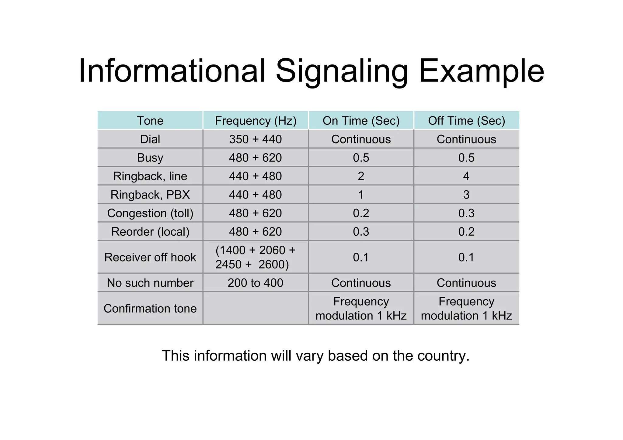
Informational Signaling Example
Frequency
modulation1 kHz
Frequency
modulation 1 kHz
Confirmation tone
Continuous
Continuous
200 to 400
No such number
0.1
0.1
(1400 + 2060 +
2450 + 2600)
Receiver off hook
0.2
0.3
480 + 620
Reorder (local)
0.3
0.2
480 + 620
Congestion (toll)
3
1
440 + 480
Ringback, PBX
4
2
440 + 480
Ringback, line
0.5
0.5
480 + 620
Busy
Continuous
Continuous
350 + 440
Dial
Off Time (Sec)
On Time (Sec)
Frequency (Hz)
Tone
This information will vary based on the country.
11.
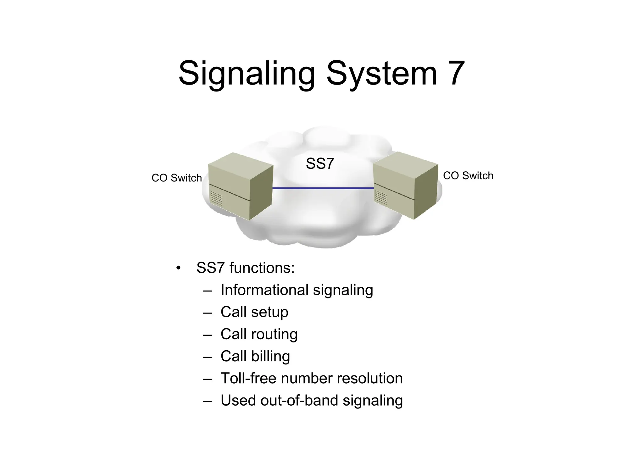
Signaling System 7
•SS7 functions:
– Informational signaling
– Call setup
– Call routing
– Call billing
– Toll-free number resolution
– Used out-of-band signaling
CO Switch CO Switch
SS7
12.
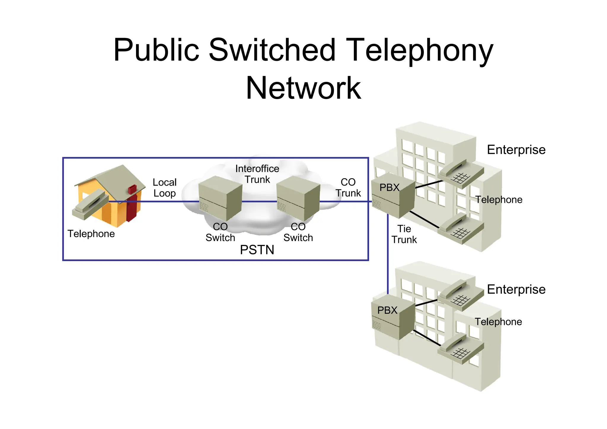
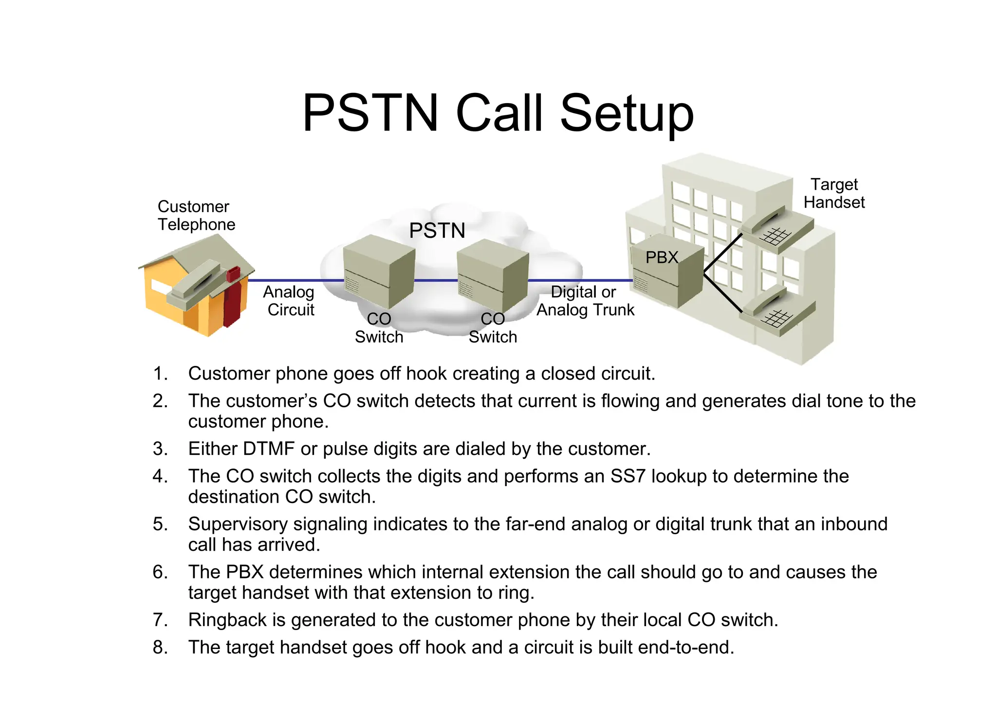
PSTN Call Setup
1.Customer phone goes off hook creating a closed circuit.
2. The customer’s CO switch detects that current is flowing and generates dial tone to the
customer phone.
3. Either DTMF or pulse digits are dialed by the customer.
4. The CO switch collects the digits and performs an SS7 lookup to determine the
destination CO switch.
5. Supervisory signaling indicates to the far-end analog or digital trunk that an inbound
call has arrived.
6. The PBX determines which internal extension the call should go to and causes the
target handset with that extension to ring.
7. Ringback is generated to the customer phone by their local CO switch.
8. The target handset goes off hook and a circuit is built end-to-end.
PSTN
Customer
Telephone
Analog
Circuit
Digital or
Analog Trunk
PBX
Target
Handset
CO
Switch
CO
Switch
13.
Numbering Plans
– Anumbering plan is a numbering scheme with the following
characteristics:
• Defines a set of rules to allocate numbers used in
telecommunications
• Is based on international telecommunications standards
• Is established by numbering plan authorities, which regulate the
distribution of numbers and codes in their territory
– Many regional and national numbering plans exist:
• NANP
• U.K. National Numbering Scheme
• ETNS
• Hong Kong
• Many countries have their own numbering plans
14.
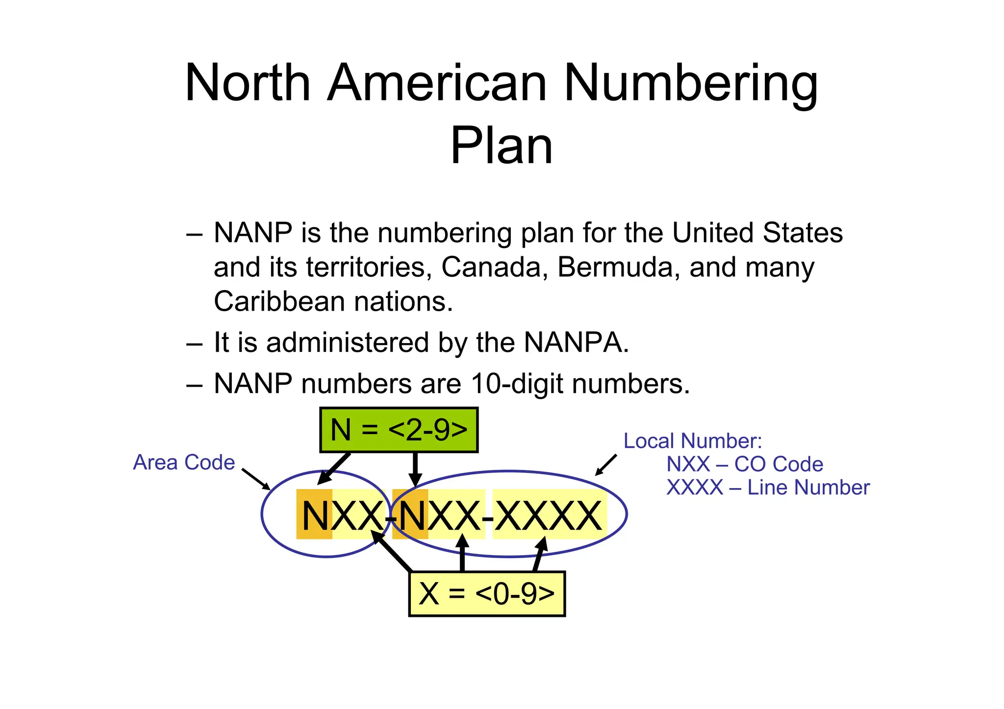
North American Numbering
Plan
–NANP is the numbering plan for the United States
and its territories, Canada, Bermuda, and many
Caribbean nations.
– It is administered by the NANPA.
– NANP numbers are 10-digit numbers.
X = <0-9>
Area Code
Local Number:
NXX – CO Code
XXXX – Line Number
N = <2-9>
NXX-NXX-XXXX
15.
E.164 Addressing
• E.164is an international numbering plan
for public telephony systems:
– A valid number contains the following
components:
• Country code
• National destination code
• Subscriber number
– Each number can be up to 15 digits long.
– The E.164 plan was developed by the ITU.
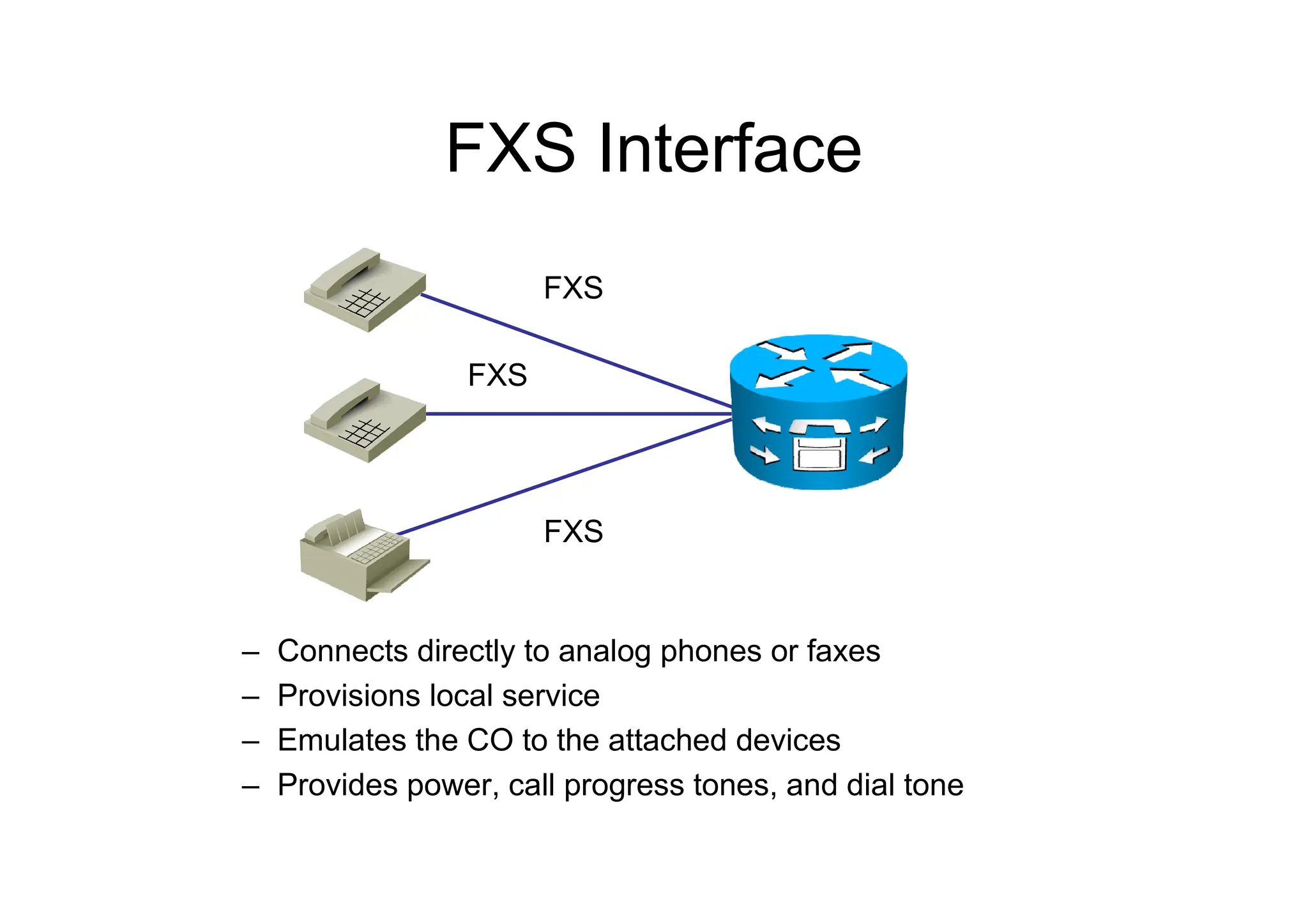
FXS Interface
– Connectsdirectly to analog phones or faxes
– Provisions local service
– Emulates the CO to the attached devices
– Provides power, call progress tones, and dial tone
FXS
FXS
FXS
19.
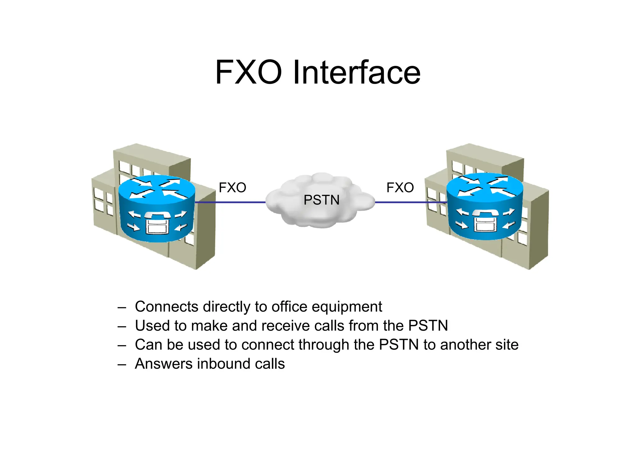
FXO Interface
– Connectsdirectly to office equipment
– Used to make and receive calls from the PSTN
– Can be used to connect through the PSTN to another site
– Answers inbound calls
FXO FXO
PSTN
20.
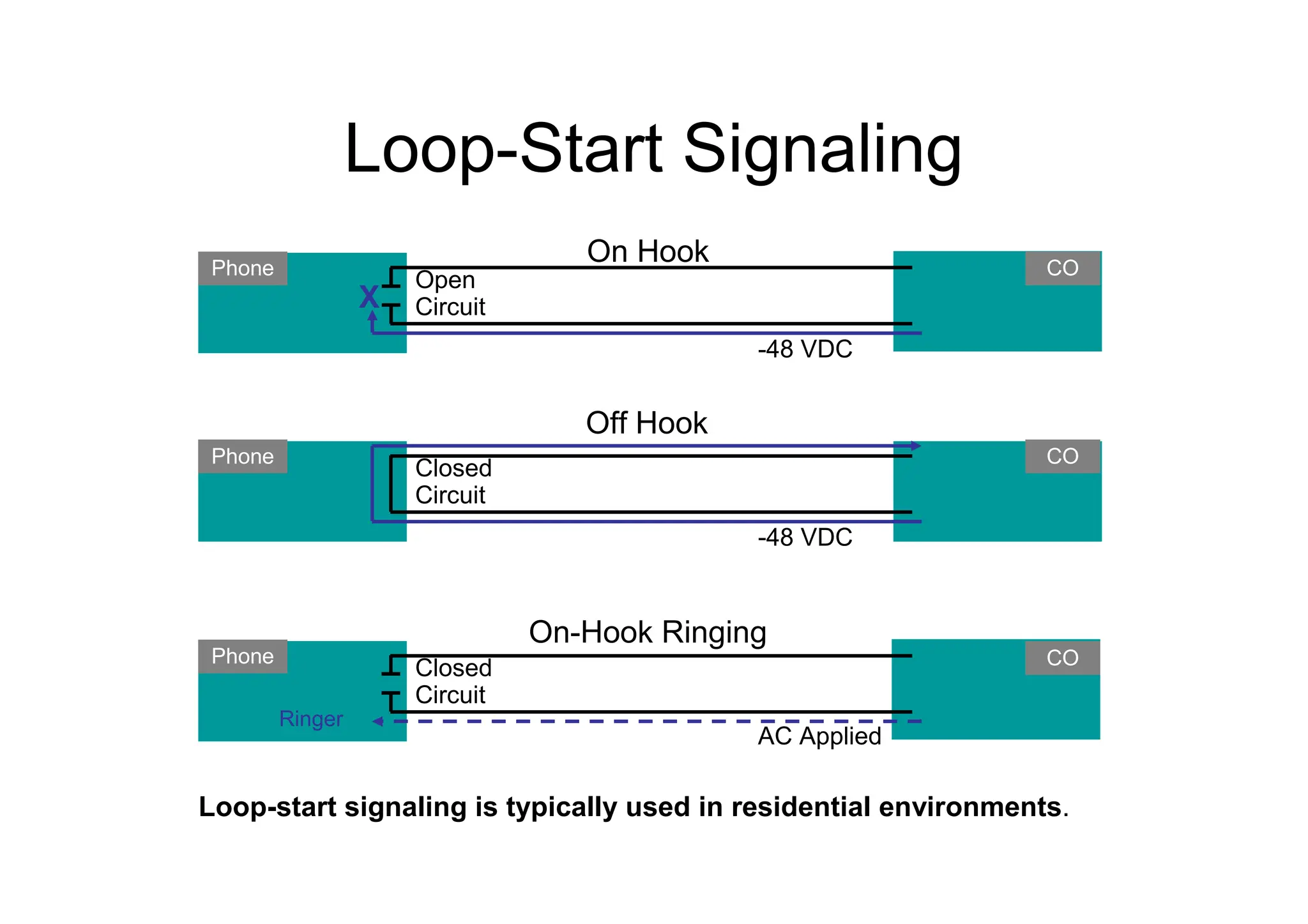
Loop-Start Signaling
CO
Phone
-48 VDC
Open
Circuit
OnHook
CO
Phone
-48 VDC
Closed
Circuit
Off Hook
CO
Phone
AC Applied
Closed
Circuit
On-Hook Ringing
Ringer
X
Loop-start signaling is typically used in residential environments.
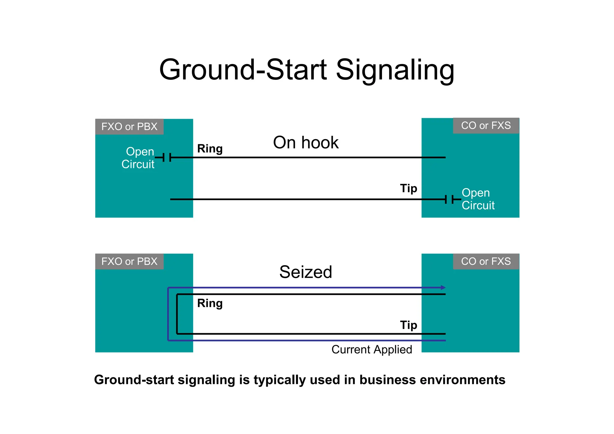
21.
Ground-Start Signaling
CO orFXS
FXO or PBX
Open
Circuit
On hook
CO or FXS
Seized
Open
Circuit
FXO or PBX
Current Applied
Ring
Tip
Ring
Tip
Ground-start signaling is typically used in business environments
22.
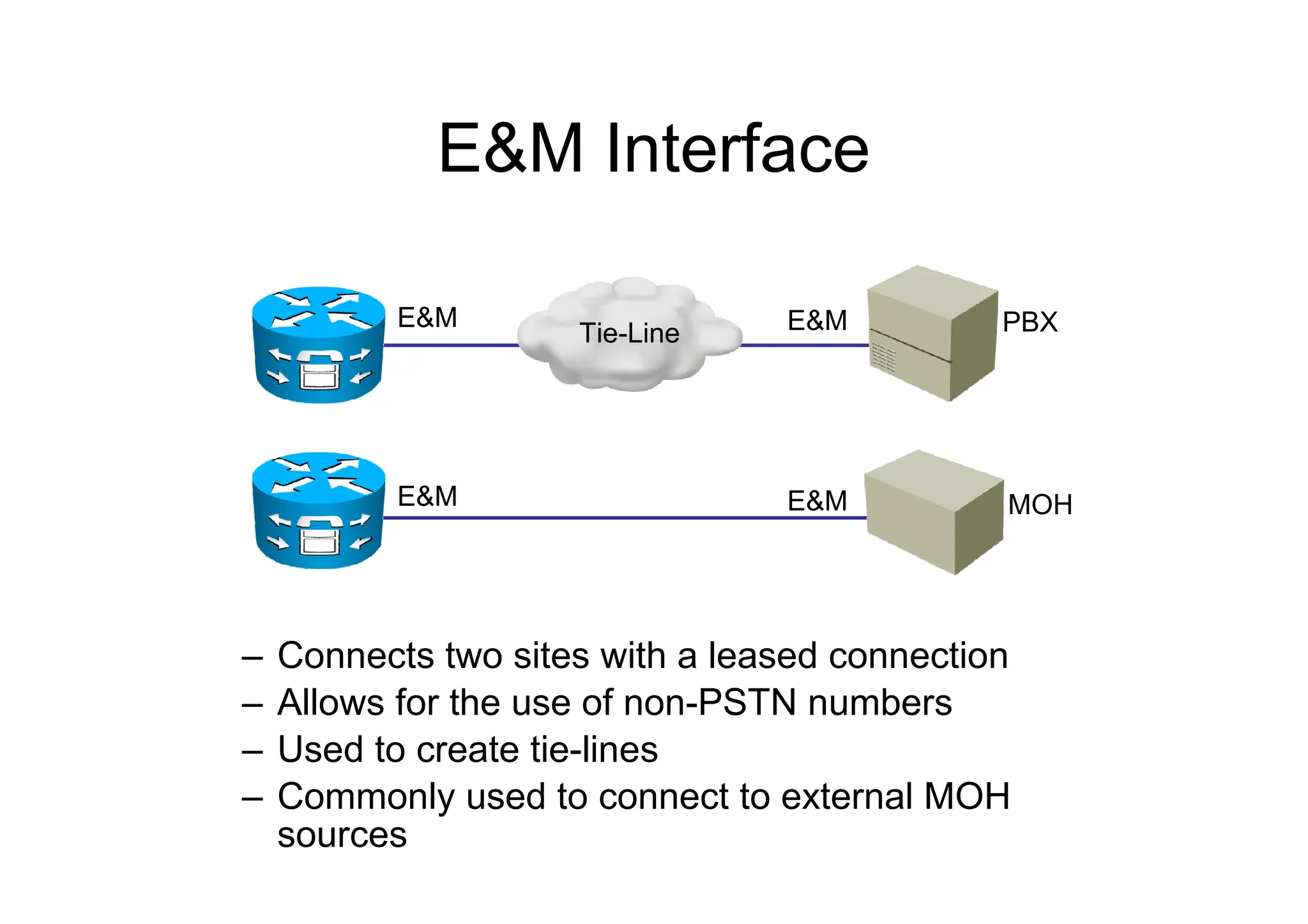
E&M Interface
– Connectstwo sites with a leased connection
– Allows for the use of non-PSTN numbers
– Used to create tie-lines
– Commonly used to connect to external MOH
sources
E&M E&M
E&M MOH
E&M
PBX
Tie-Line
Digitizing Analog Signals
1.Sample the analog signal regularly.
2. Quantize the sample.
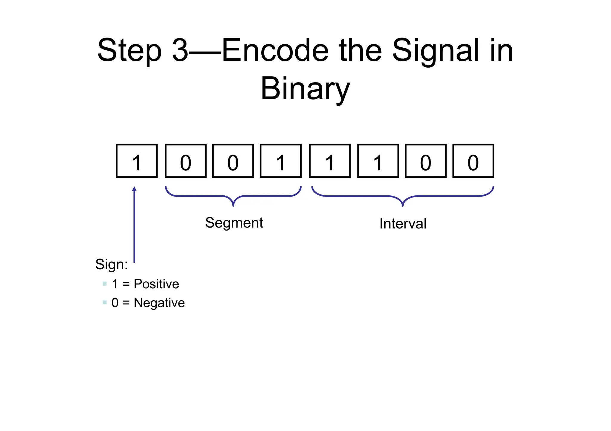
3. Encode the value into a binary expression.
4. Compress the samples to reduce bandwidth
(optional).
25.
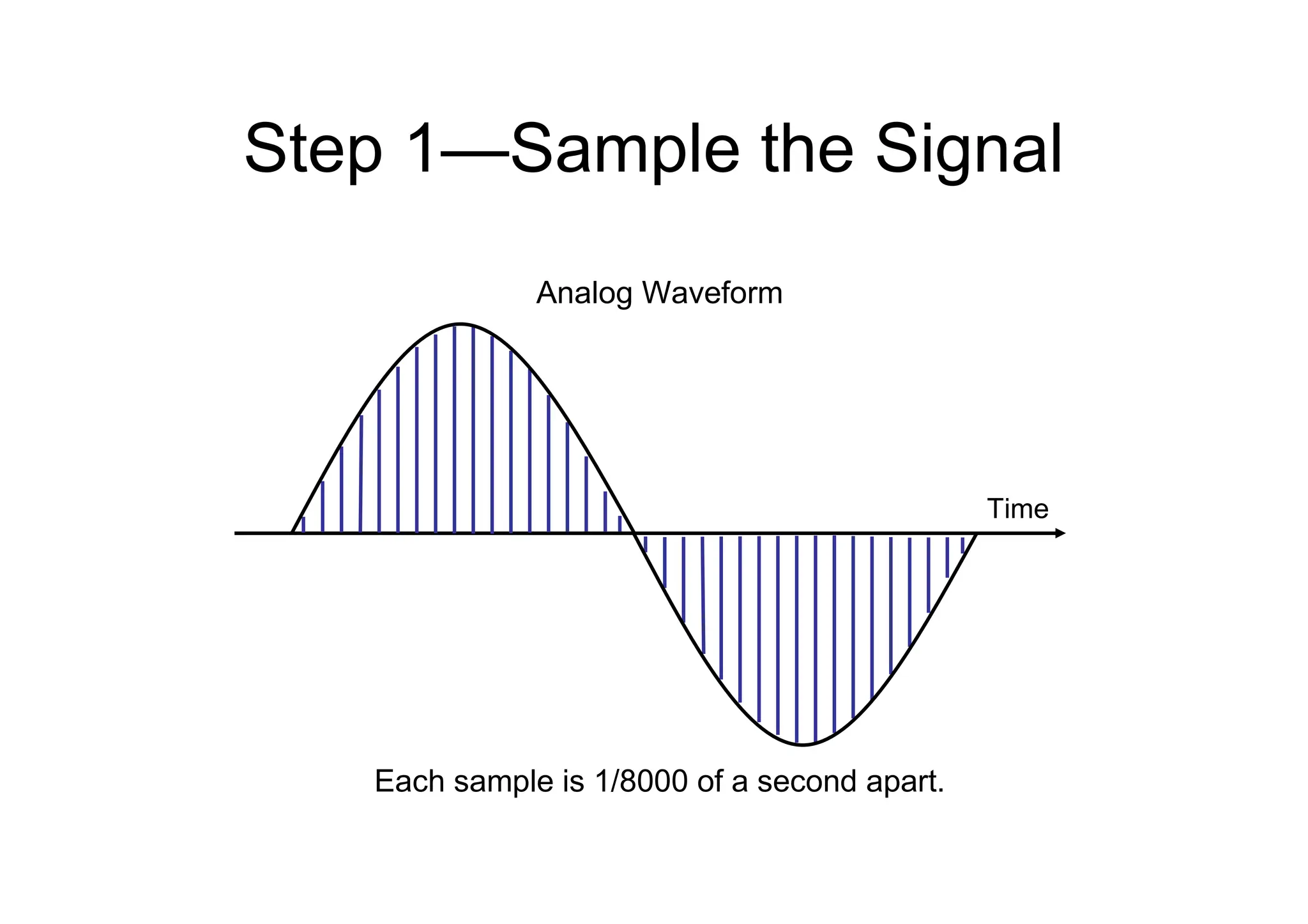
Step 1—Sample theSignal
Each sample is 1/8000 of a second apart.
Time
Analog Waveform
26.
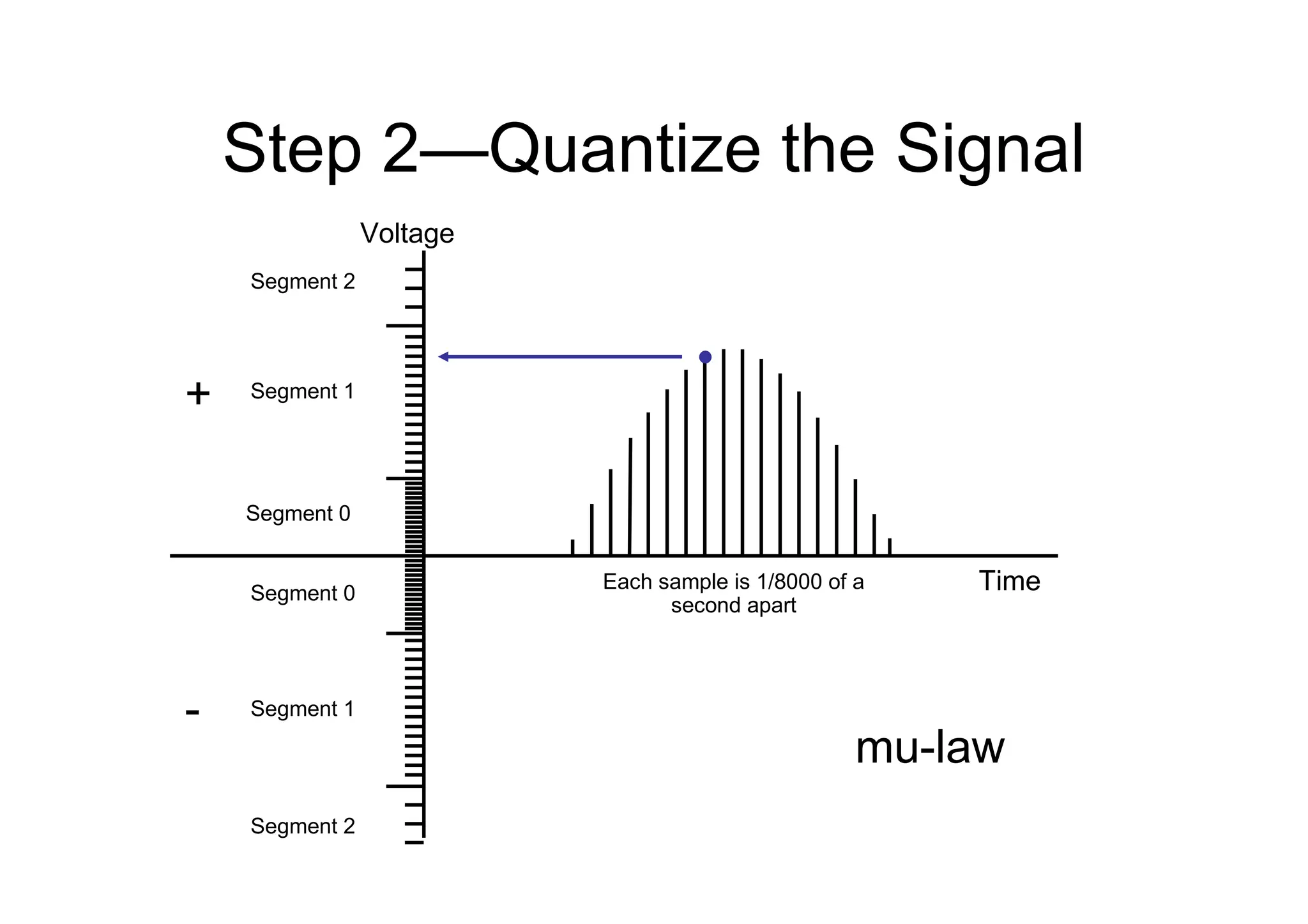
Step 2—Quantize theSignal
Segment 0
Segment 0
Segment 1
Segment 2
Segment 2
Segment 1
Time
Voltage
Each sample is 1/8000 of a
second apart
+
-
mu-law
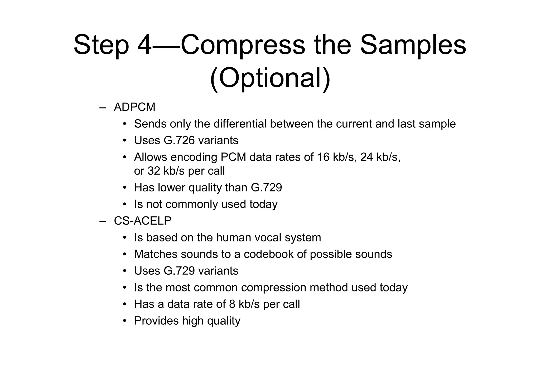
Step 4—Compress theSamples
(Optional)
– ADPCM
• Sends only the differential between the current and last sample
• Uses G.726 variants
• Allows encoding PCM data rates of 16 kb/s, 24 kb/s,
or 32 kb/s per call
• Has lower quality than G.729
• Is not commonly used today
– CS-ACELP
• Is based on the human vocal system
• Matches sounds to a codebook of possible sounds
• Uses G.729 variants
• Is the most common compression method used today
• Has a data rate of 8 kb/s per call
• Provides high quality
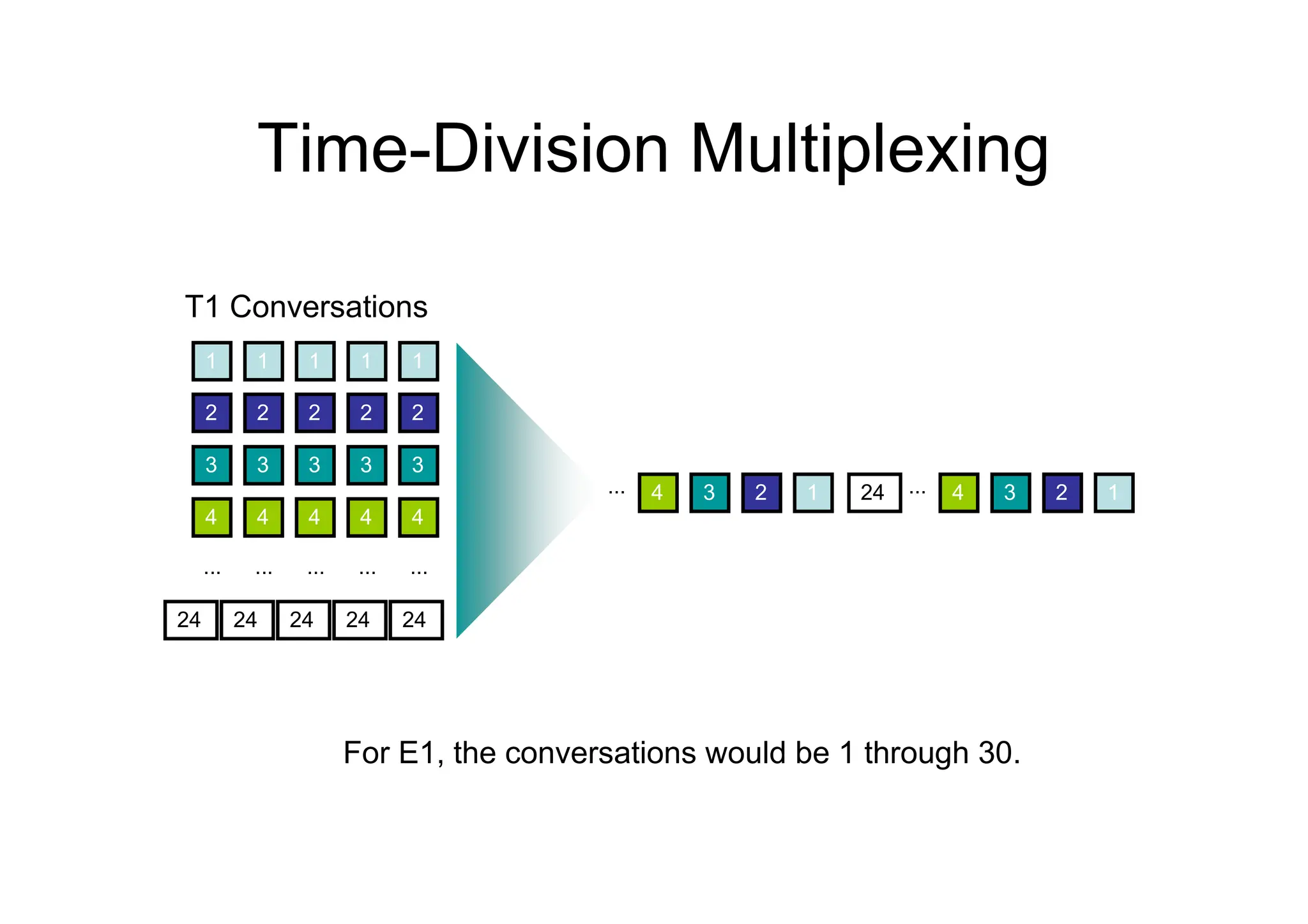
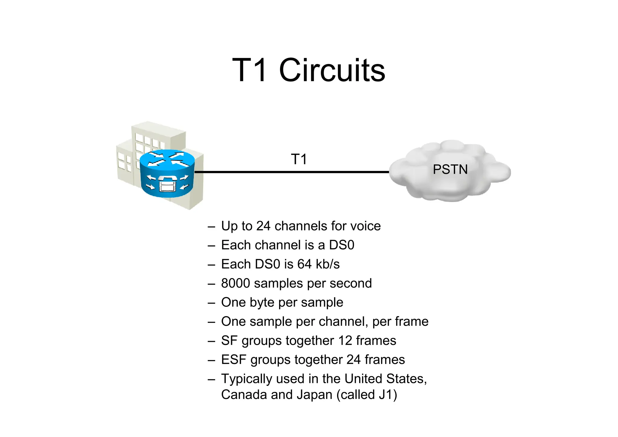
T1 Circuits
– Upto 24 channels for voice
– Each channel is a DS0
– Each DS0 is 64 kb/s
– 8000 samples per second
– One byte per sample
– One sample per channel, per frame
– SF groups together 12 frames
– ESF groups together 24 frames
– Typically used in the United States,
Canada and Japan (called J1)
T1
PSTN
31.
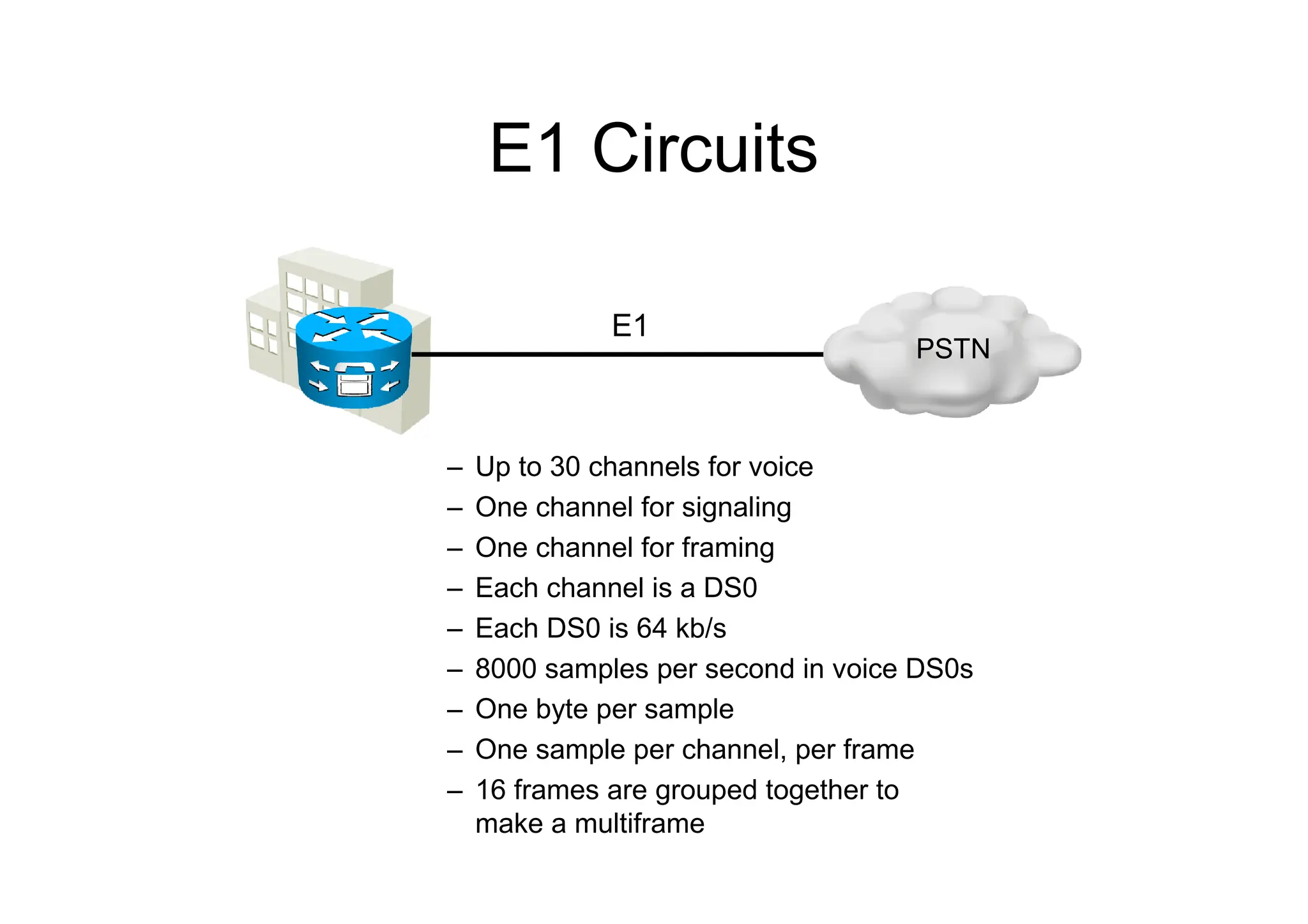
E1 Circuits
– Upto 30 channels for voice
– One channel for signaling
– One channel for framing
– Each channel is a DS0
– Each DS0 is 64 kb/s
– 8000 samples per second in voice DS0s
– One byte per sample
– One sample per channel, per frame
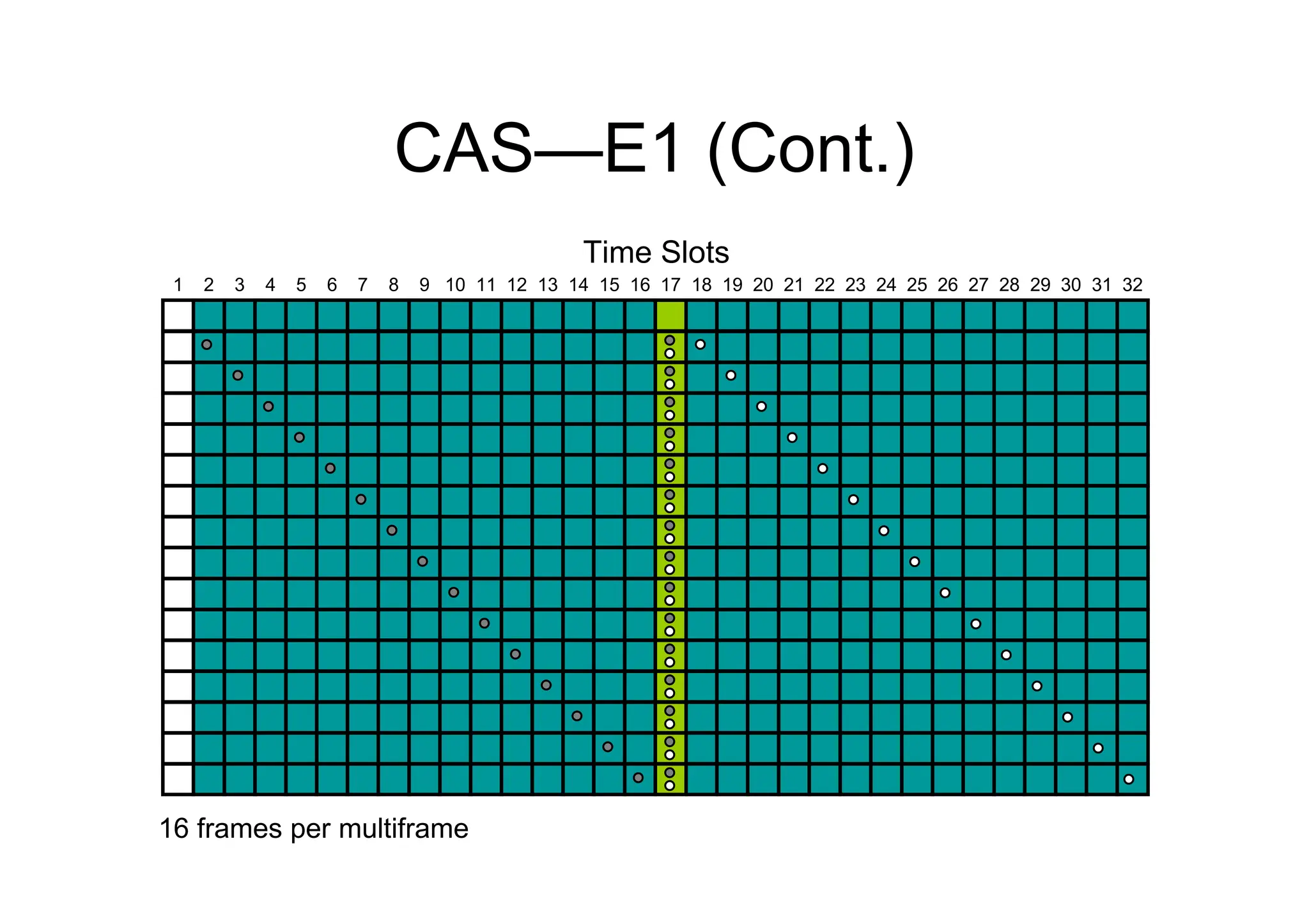
– 16 frames are grouped together to
make a multiframe
E1
PSTN
32.
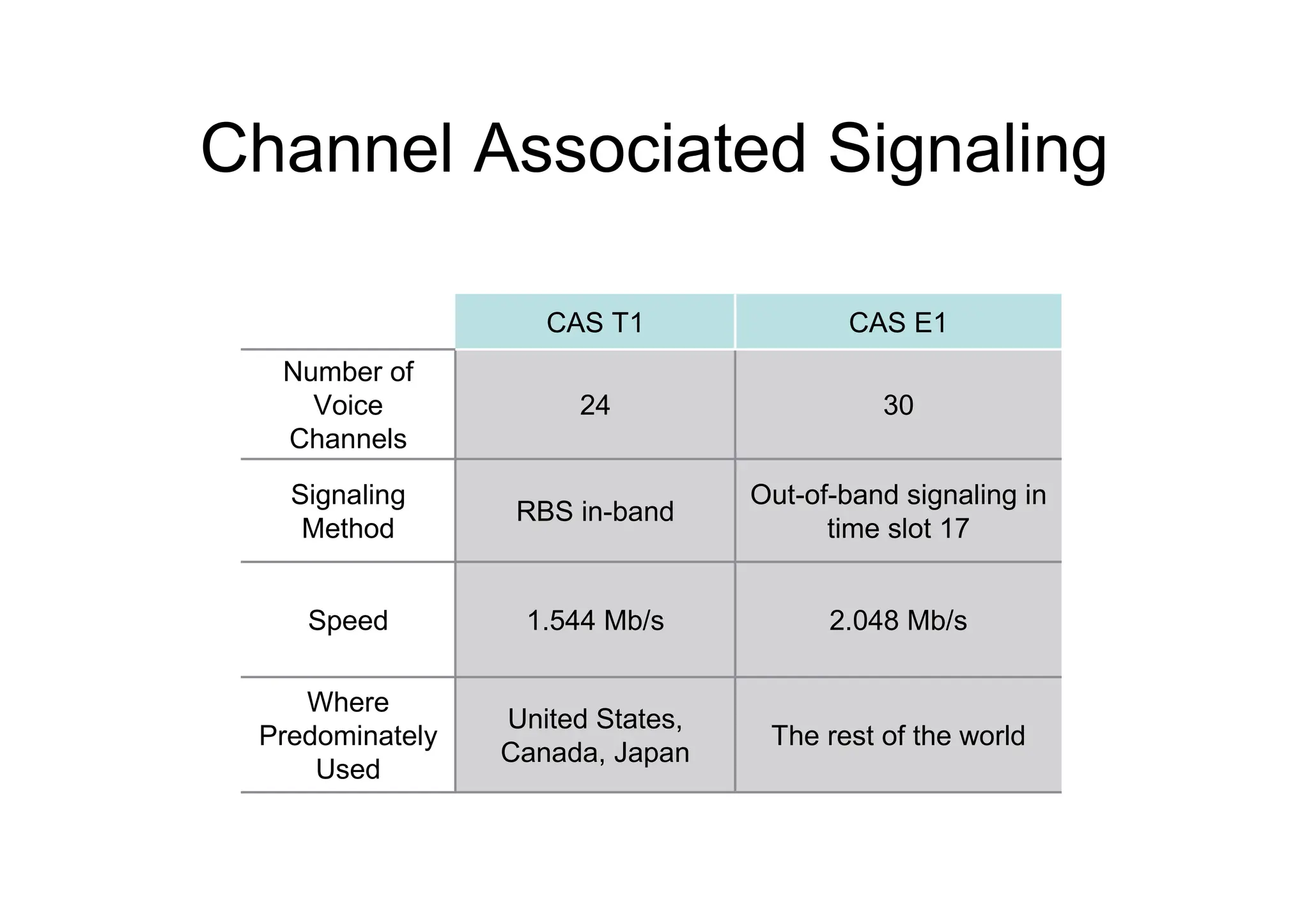
Channel Associated Signaling
2.048Mb/s
1.544 Mb/s
Speed
The rest of the world
United States,
Canada, Japan
Where
Predominately
Used
Out-of-band signaling in
time slot 17
RBS in-band
Signaling
Method
30
24
Number of
Voice
Channels
CAS E1
CAS T1
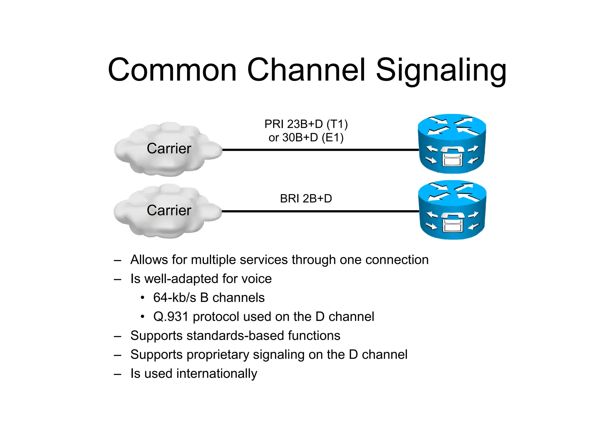
Common Channel Signaling
–Allows for multiple services through one connection
– Is well-adapted for voice
• 64-kb/s B channels
• Q.931 protocol used on the D channel
– Supports standards-based functions
– Supports proprietary signaling on the D channel
– Is used internationally
PRI 23B+D (T1)
or 30B+D (E1)
BRI 2B+D
Carrier
Carrier
37.
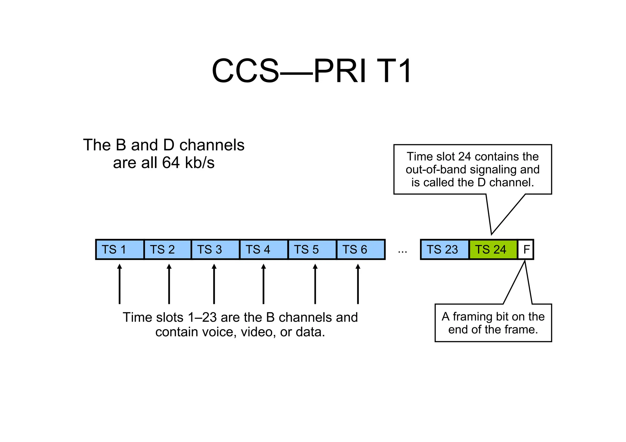
CCS—PRI T1
Time slots1–23 are the B channels and
contain voice, video, or data.
TS 1 TS 2 TS 3 TS 4 TS 5 TS 6 ... TS 23 TS 24 F
The B and D channels
are all 64 kb/s Time slot 24 contains the
out-of-band signaling and
is called the D channel.
A framing bit on the
end of the frame.
38.
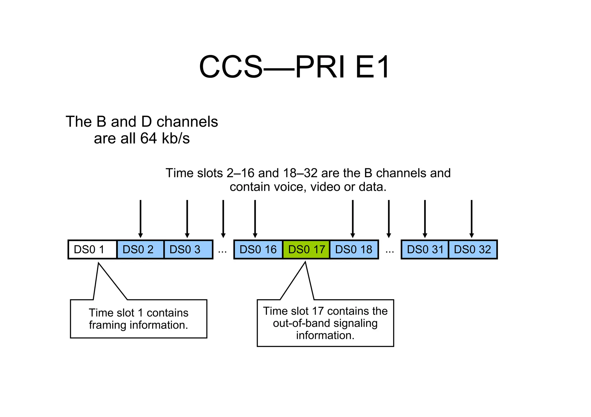
CCS—PRI E1
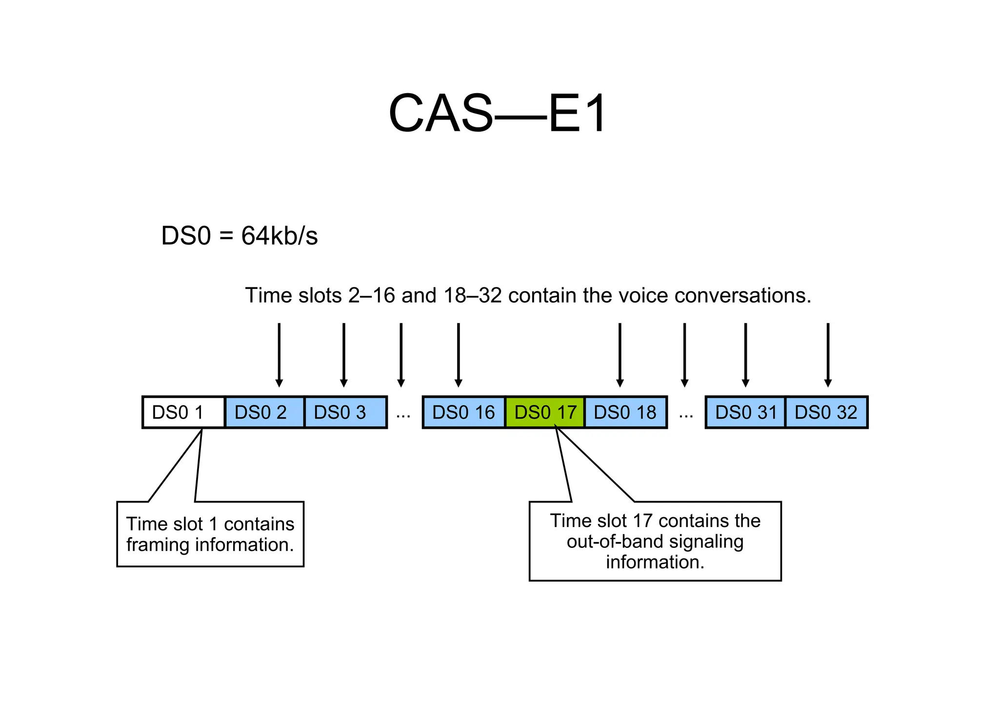
Time slots2–16 and 18–32 are the B channels and
contain voice, video or data.
The B and D channels
are all 64 kb/s
Time slot 17 contains the
out-of-band signaling
information.
Time slot 1 contains
framing information.
DS0 1 DS0 2 DS0 3 ... DS0 31
DS0 16 DS0 17 ... DS0 32
DS0 18
39.
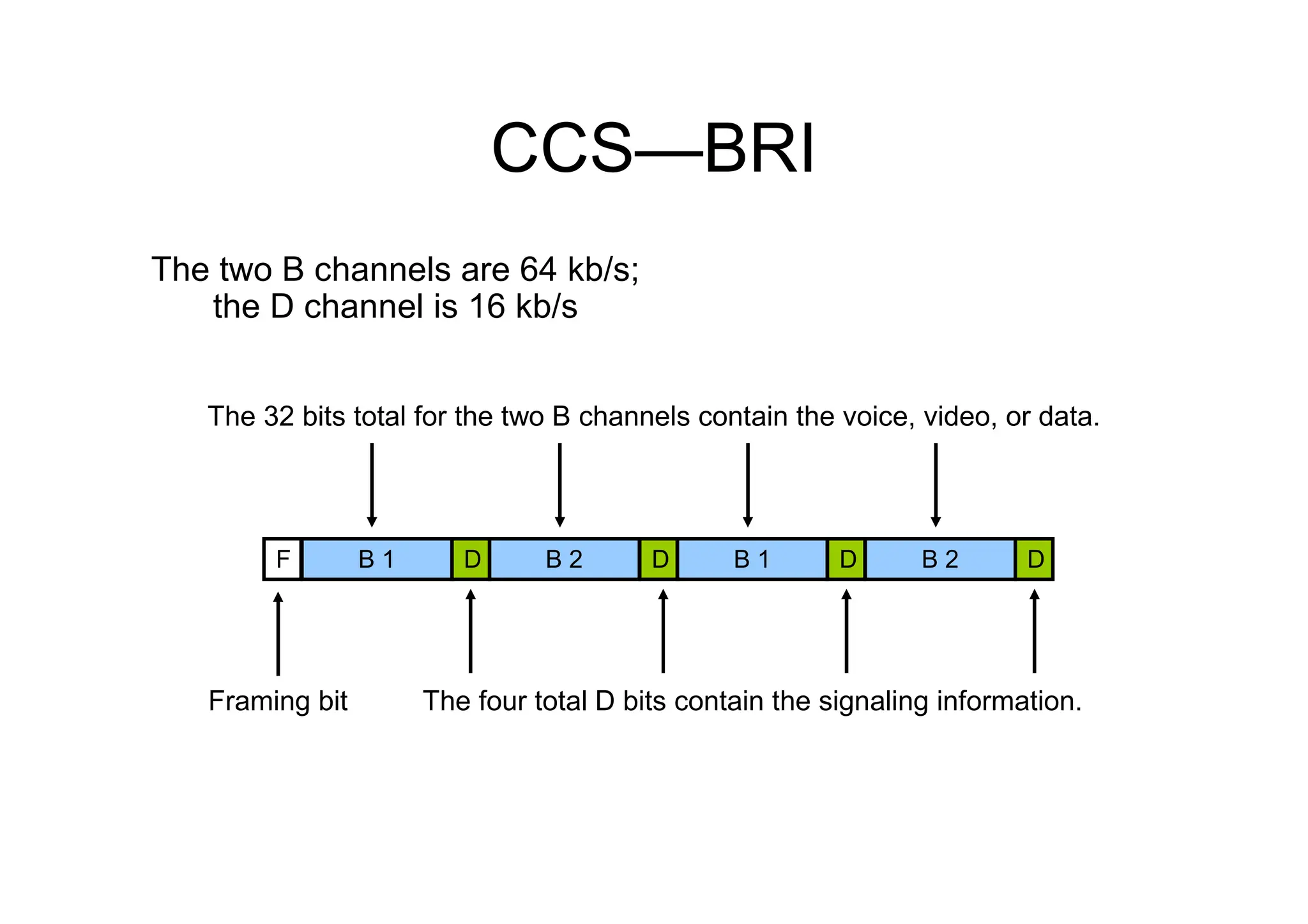
CCS—BRI
Framing bit
The 32bits total for the two B channels contain the voice, video, or data.
The four total D bits contain the signaling information.
The two B channels are 64 kb/s;
the D channel is 16 kb/s
F B 1 B 2 B 1 B 2
D D D D
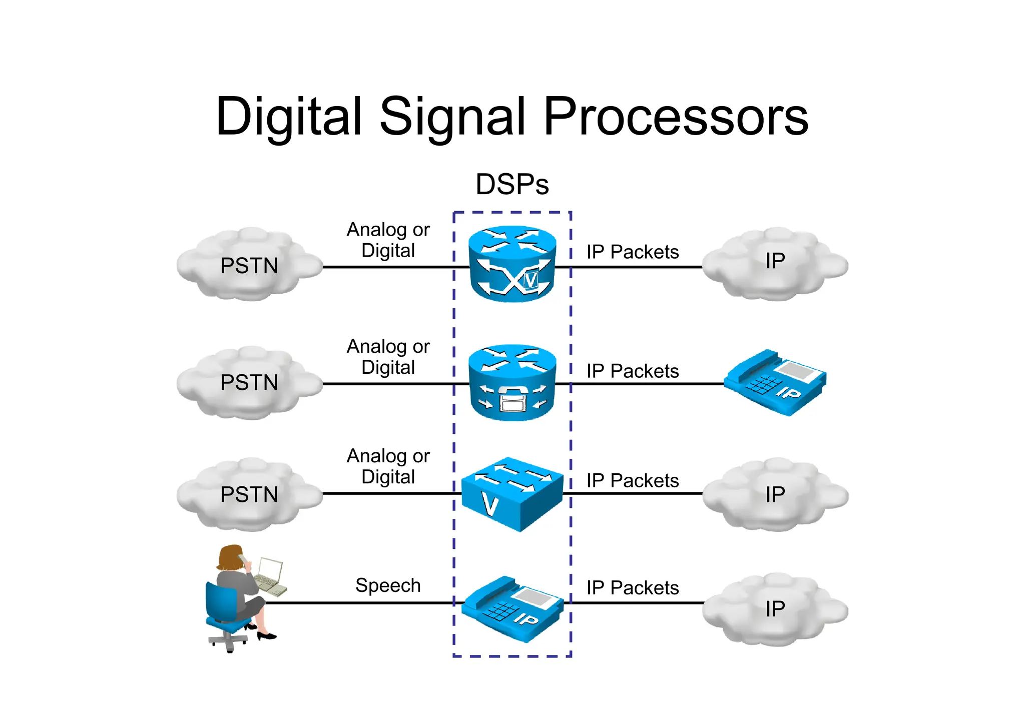
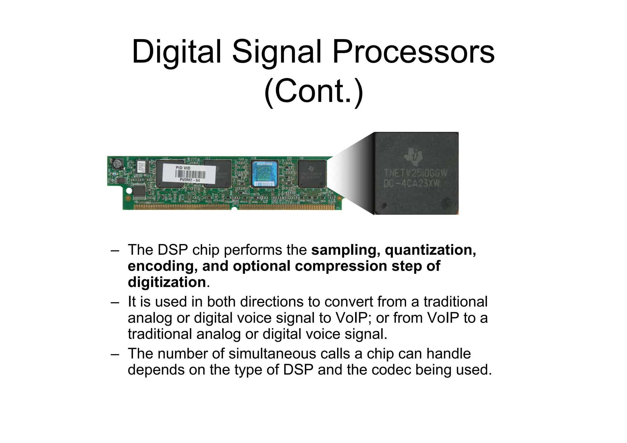
Digital Signal Processors
(Cont.)
–The DSP chip performs the sampling, quantization,
encoding, and optional compression step of
digitization.
– It is used in both directions to convert from a traditional
analog or digital voice signal to VoIP; or from VoIP to a
traditional analog or digital voice signal.
– The number of simultaneous calls a chip can handle
depends on the type of DSP and the codec being used.
43.
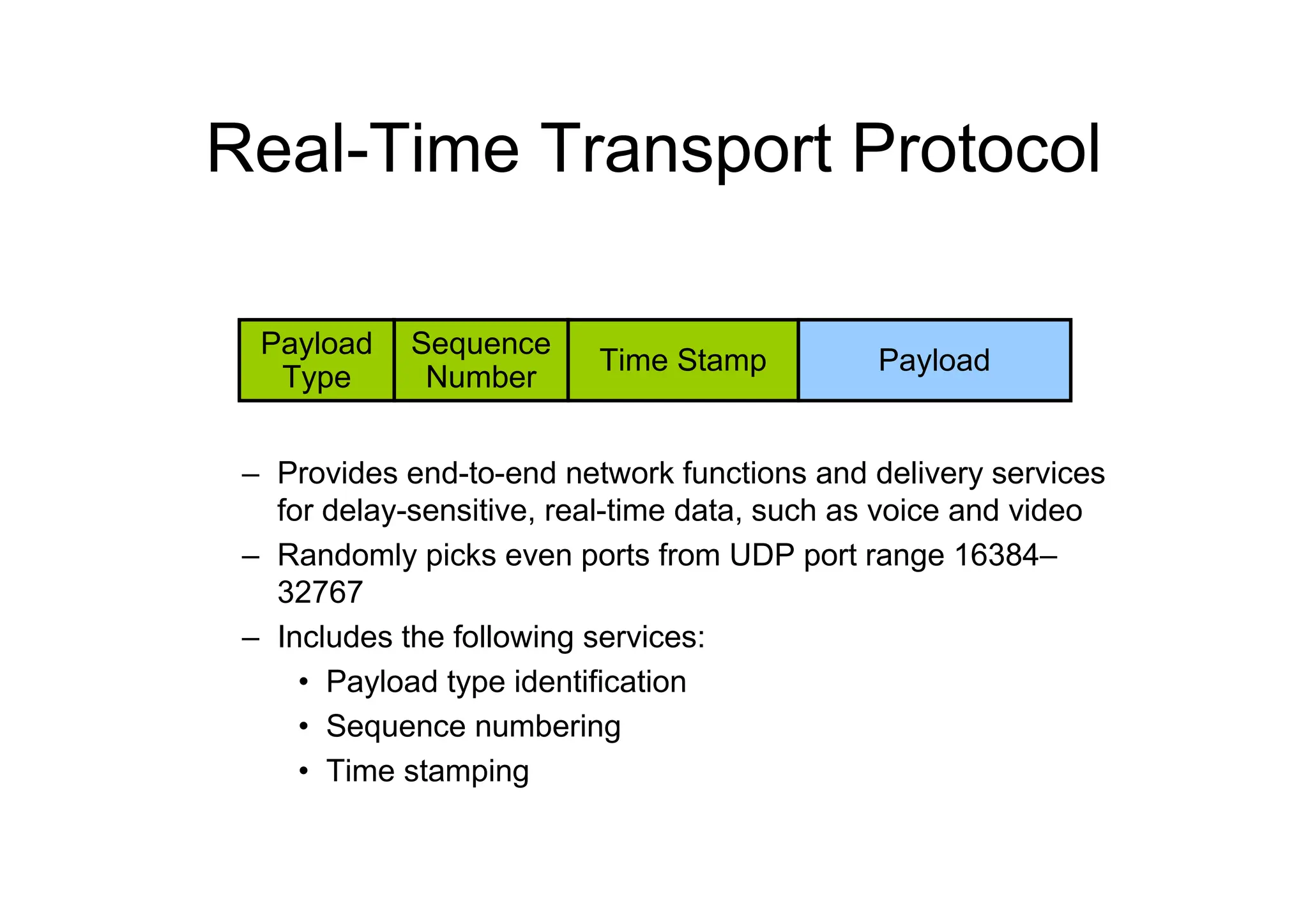
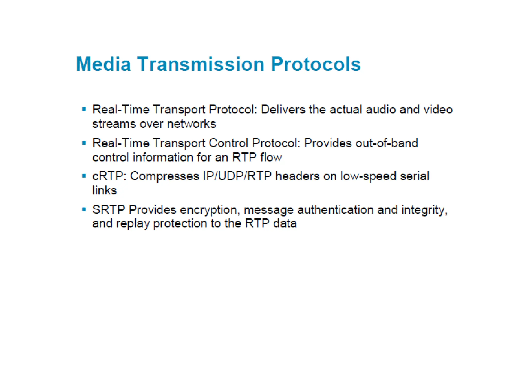
Real-Time Transport Protocol
–Provides end-to-end network functions and delivery services
for delay-sensitive, real-time data, such as voice and video
– Randomly picks even ports from UDP port range 16384–
32767
– Includes the following services:
• Payload type identification
• Sequence numbering
• Time stamping
Payload
Type
Sequence
Number
Time Stamp Payload
44.
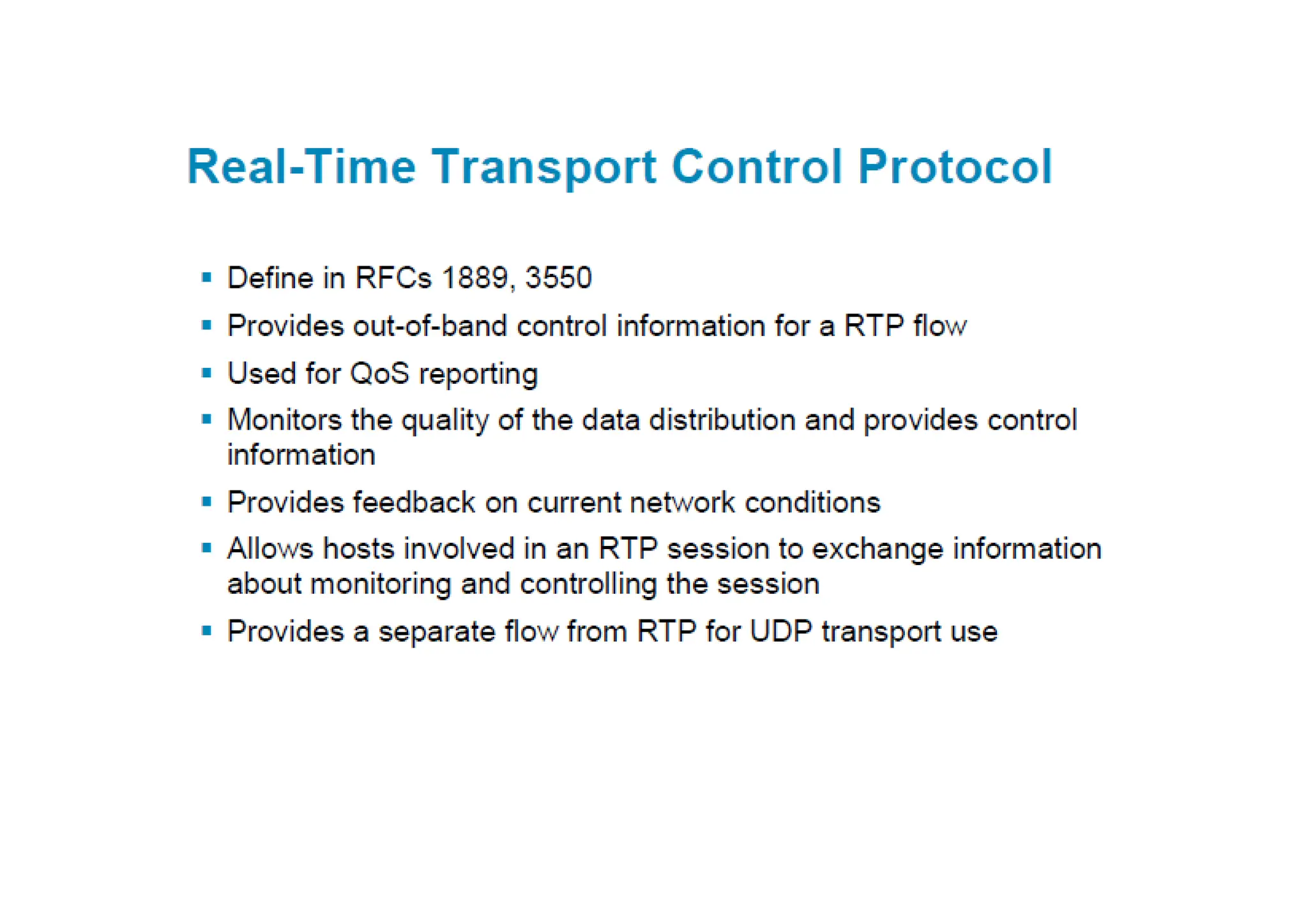
RTP Control Protocol
–Can be used to monitor the quality of the data distribution and
provide control information
– Provides feedback on current network conditions
– Allows hosts that are involved in an RTP session to exchange
information about monitoring and controlling the session:
• Packet count
• Packet delay
• Octet count
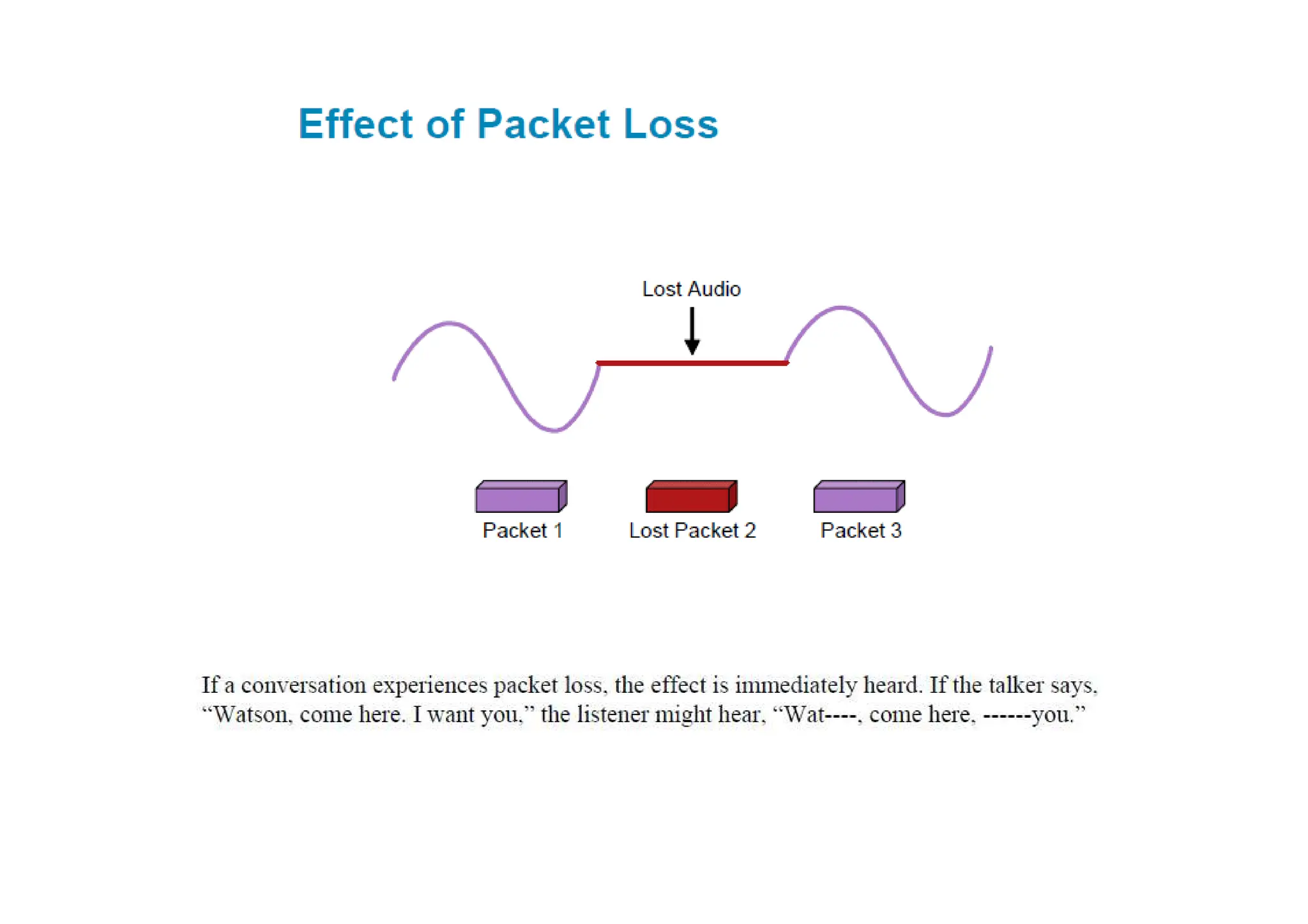
• Packet loss
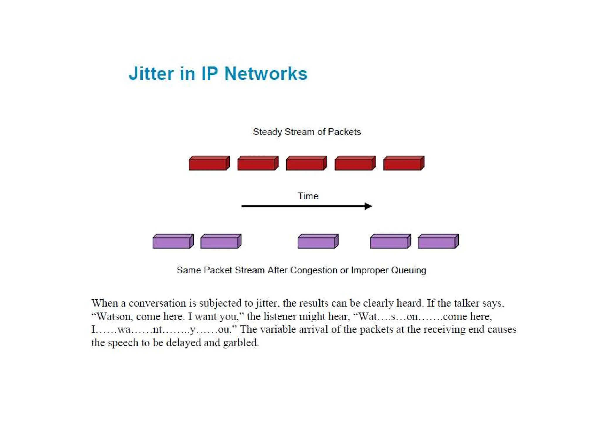
• Jitter (variation in delay)
– Provides a separate flow from RTP for UDP transport use
– Is paired with its RTP stream and uses the same port as the
RTP stream plus 1 (odd-numbered port)
45.
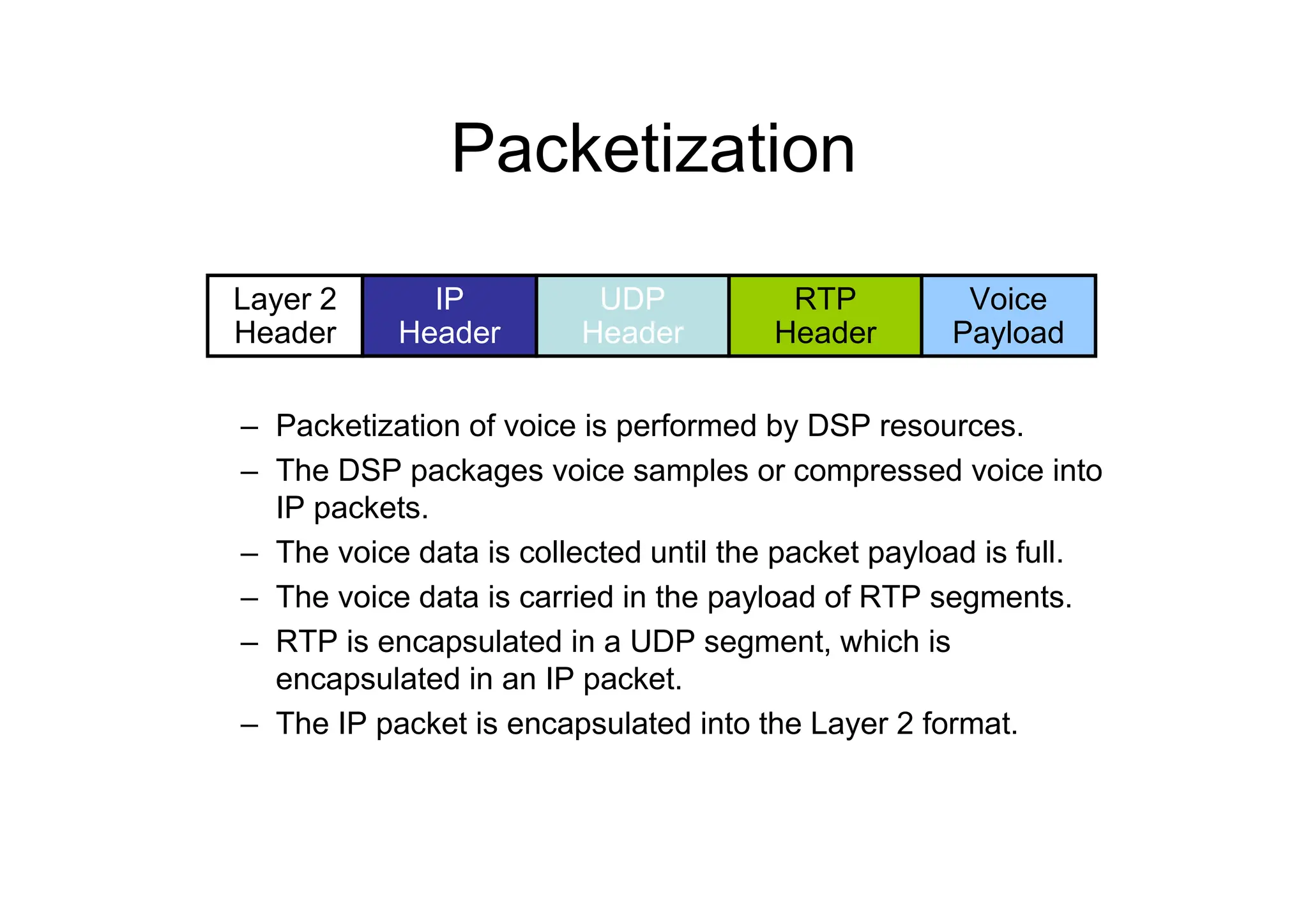
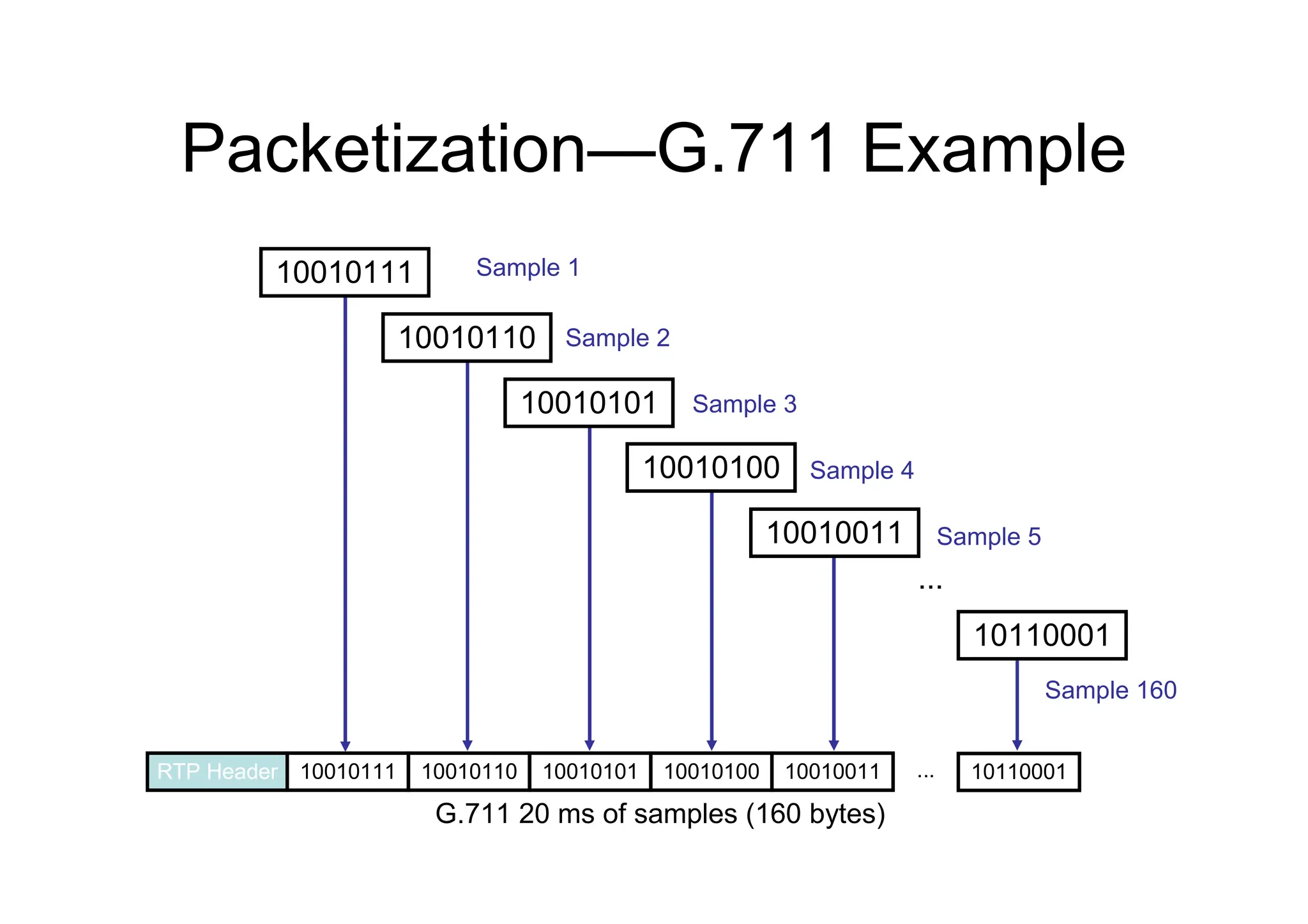
Packetization
– Packetization ofvoice is performed by DSP resources.
– The DSP packages voice samples or compressed voice into
IP packets.
– The voice data is collected until the packet payload is full.
– The voice data is carried in the payload of RTP segments.
– RTP is encapsulated in a UDP segment, which is
encapsulated in an IP packet.
– The IP packet is encapsulated into the Layer 2 format.
Layer 2
Header
IP
Header
UDP
Header
Voice
Payload
RTP
Header
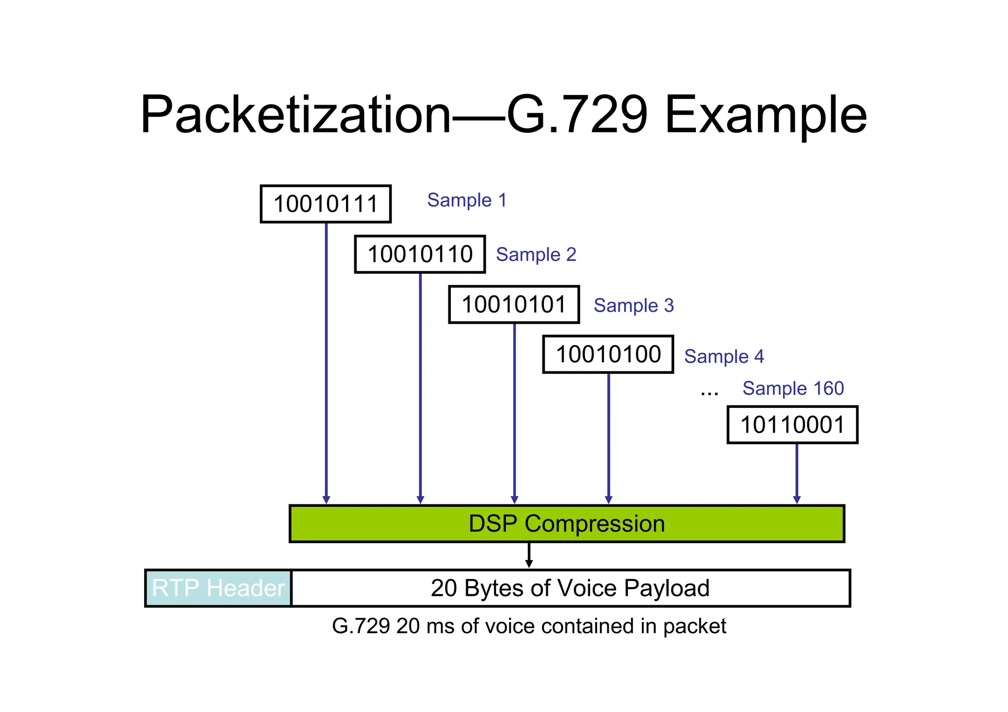
Packetization—G.729 Example
...
20 Bytesof Voice Payload
RTP Header
Sample 1
Sample 2
Sample 3
Sample 4
Sample 160
G.729 20 ms of voice contained in packet
DSP Compression
10010111
10010110
10010101
10010100
10110001
48.
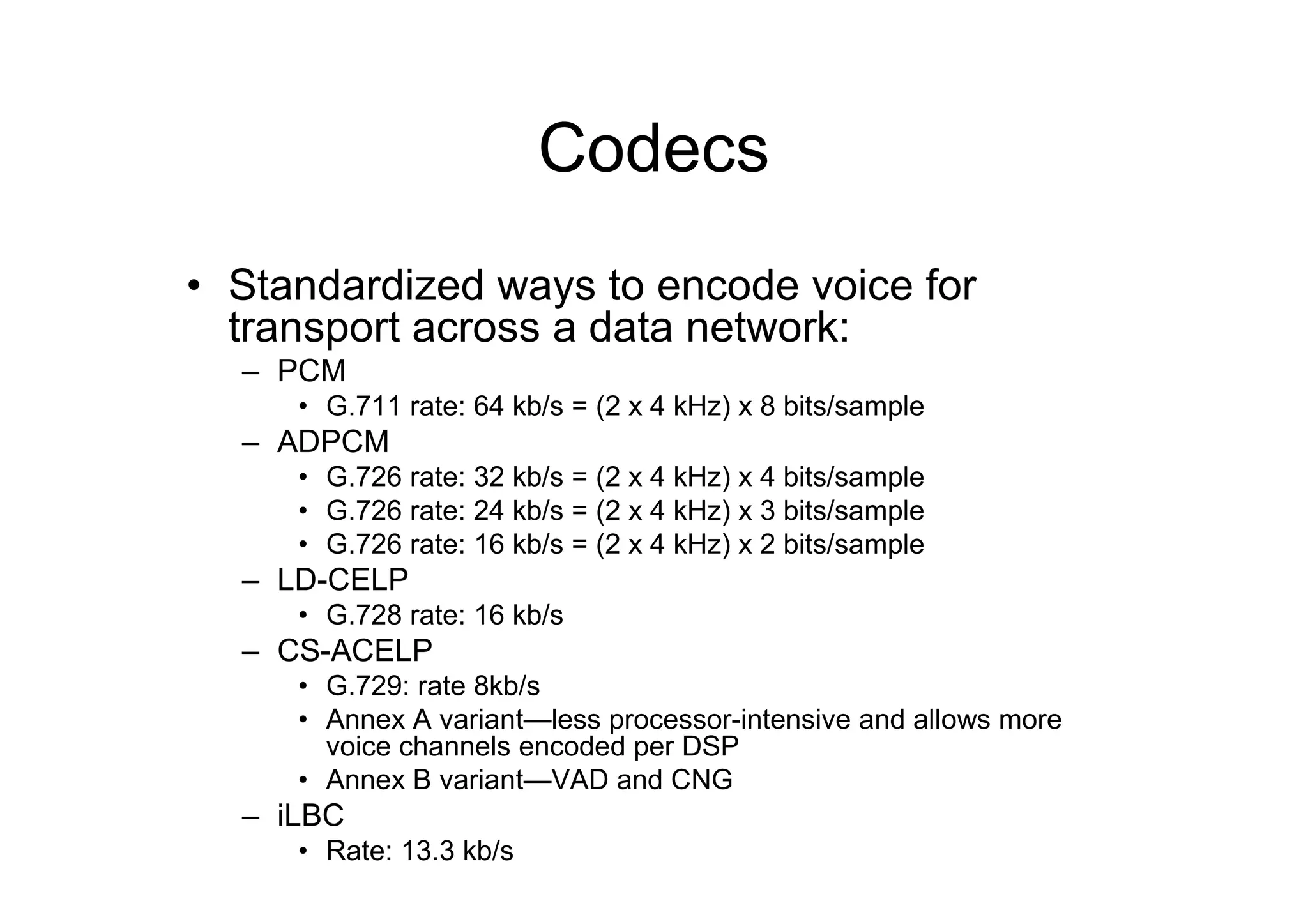
Codecs
• Standardized waysto encode voice for
transport across a data network:
– PCM
• G.711 rate: 64 kb/s = (2 x 4 kHz) x 8 bits/sample
– ADPCM
• G.726 rate: 32 kb/s = (2 x 4 kHz) x 4 bits/sample
• G.726 rate: 24 kb/s = (2 x 4 kHz) x 3 bits/sample
• G.726 rate: 16 kb/s = (2 x 4 kHz) x 2 bits/sample
– LD-CELP
• G.728 rate: 16 kb/s
– CS-ACELP
• G.729: rate 8kb/s
• Annex A variant—less processor-intensive and allows more
voice channels encoded per DSP
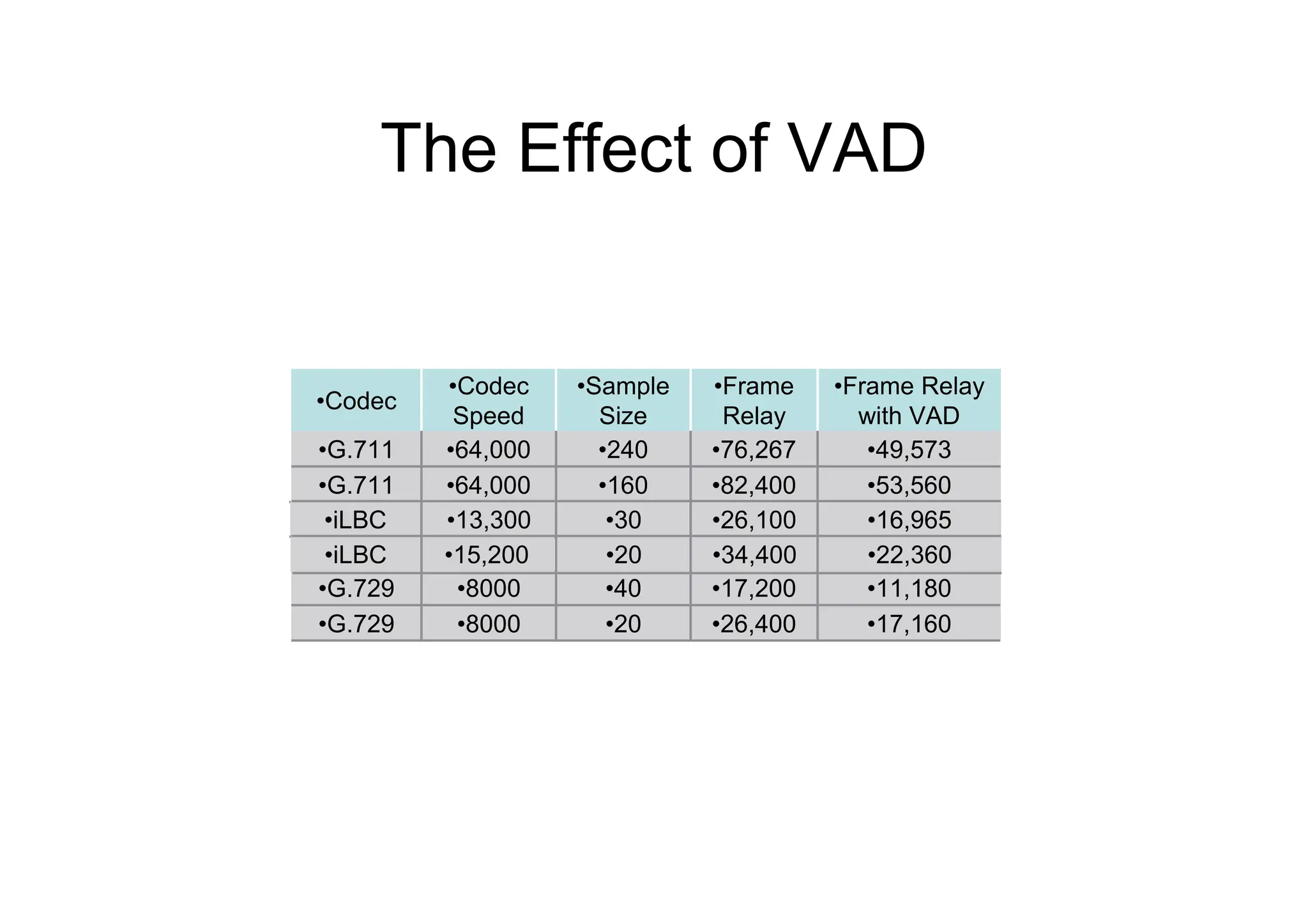
• Annex B variant—VAD and CNG
– iLBC
• Rate: 13.3 kb/s
49.
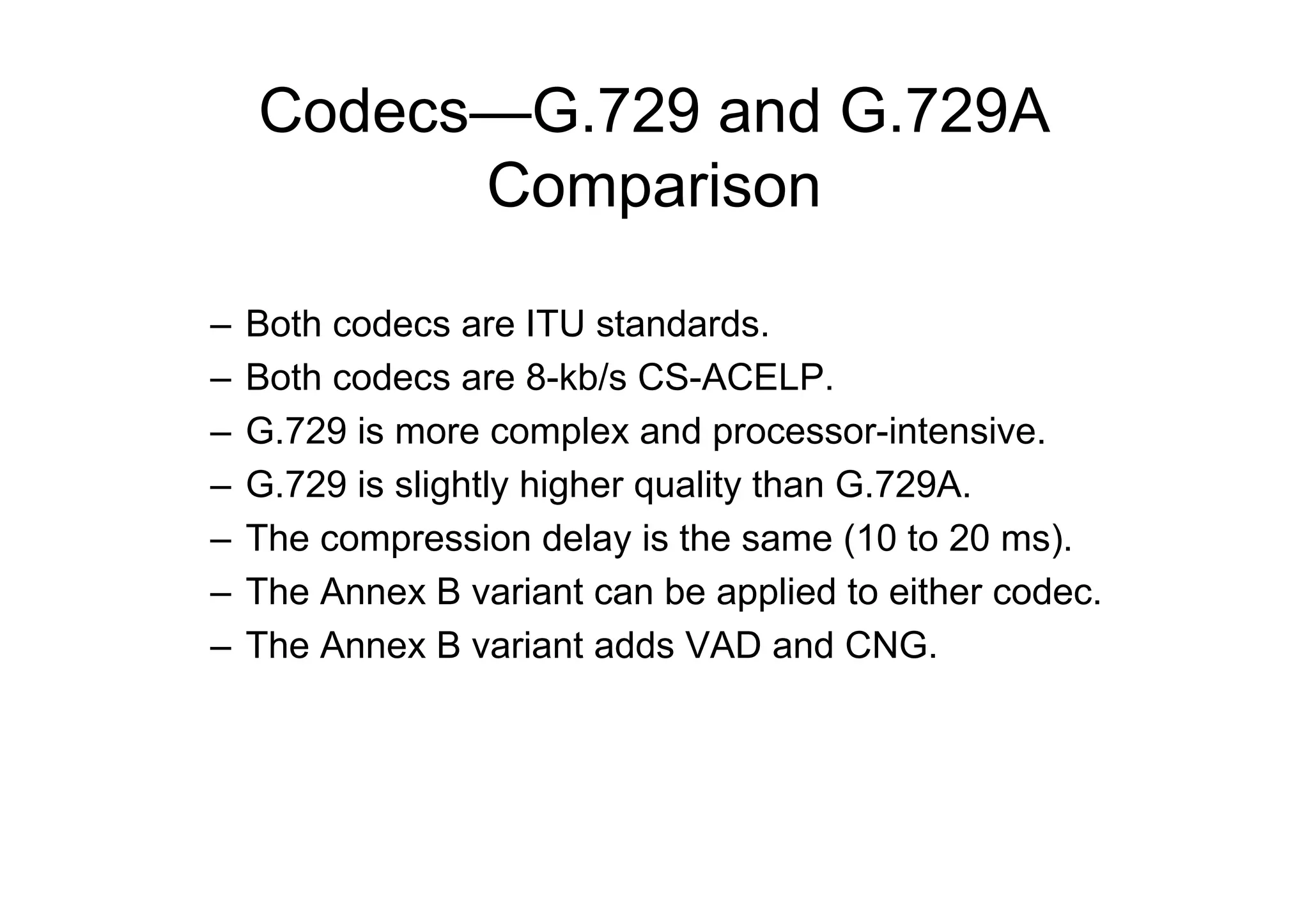
Codecs—G.729 and G.729A
Comparison
–Both codecs are ITU standards.
– Both codecs are 8-kb/s CS-ACELP.
– G.729 is more complex and processor-intensive.
– G.729 is slightly higher quality than G.729A.
– The compression delay is the same (10 to 20 ms).
– The Annex B variant can be applied to either codec.
– The Annex B variant adds VAD and CNG.
50.
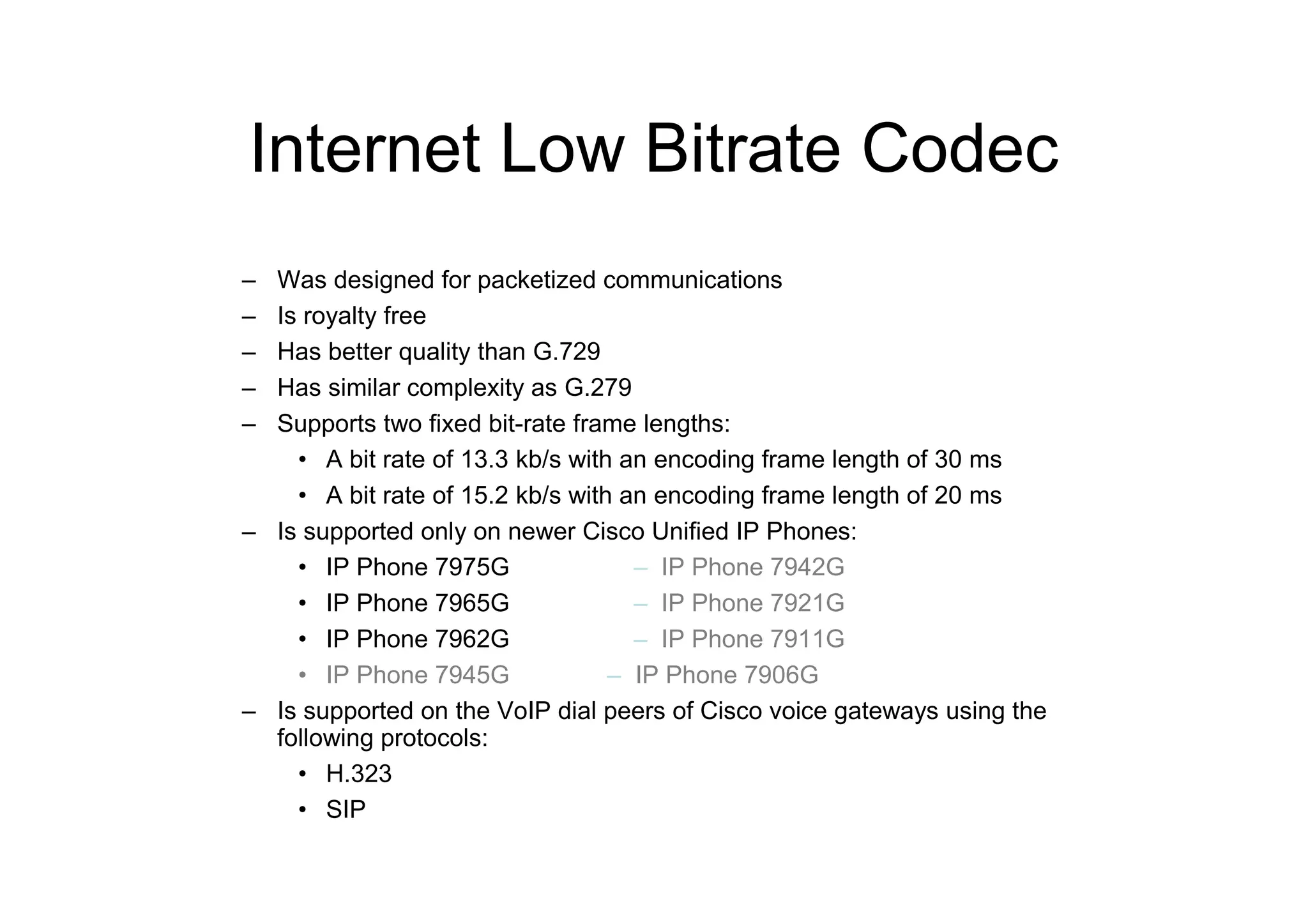
Internet Low BitrateCodec
– Was designed for packetized communications
– Is royalty free
– Has better quality than G.729
– Has similar complexity as G.279
– Supports two fixed bit-rate frame lengths:
• A bit rate of 13.3 kb/s with an encoding frame length of 30 ms
• A bit rate of 15.2 kb/s with an encoding frame length of 20 ms
– Is supported only on newer Cisco Unified IP Phones:
• IP Phone 7975G – IP Phone 7942G
• IP Phone 7965G – IP Phone 7921G
• IP Phone 7962G – IP Phone 7911G
• IP Phone 7945G – IP Phone 7906G
– Is supported on the VoIP dial peers of Cisco voice gateways using the
following protocols:
• H.323
• SIP
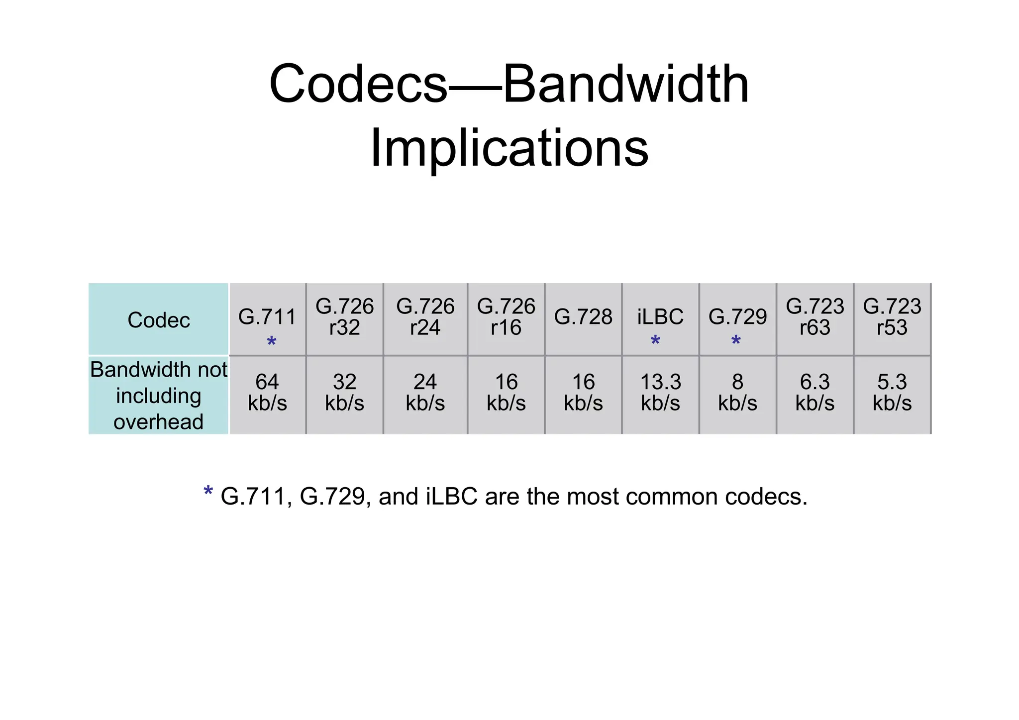
Codecs—Bandwidth
Implications
*
* G.711, G.729,and iLBC are the most common codecs.
13.3
kb/s
iLBC
16
kb/s
G.728
8
kb/s
G.729
6.3
kb/s
G.723
r63
16
kb/s
G.726
r16
5.3
kb/s
24
kb/s
32
kb/s
64
kb/s
Bandwidth not
including
overhead
G.723
r53
G.726
r24
G.726
r32
G.711
Codec
* *
*
53.
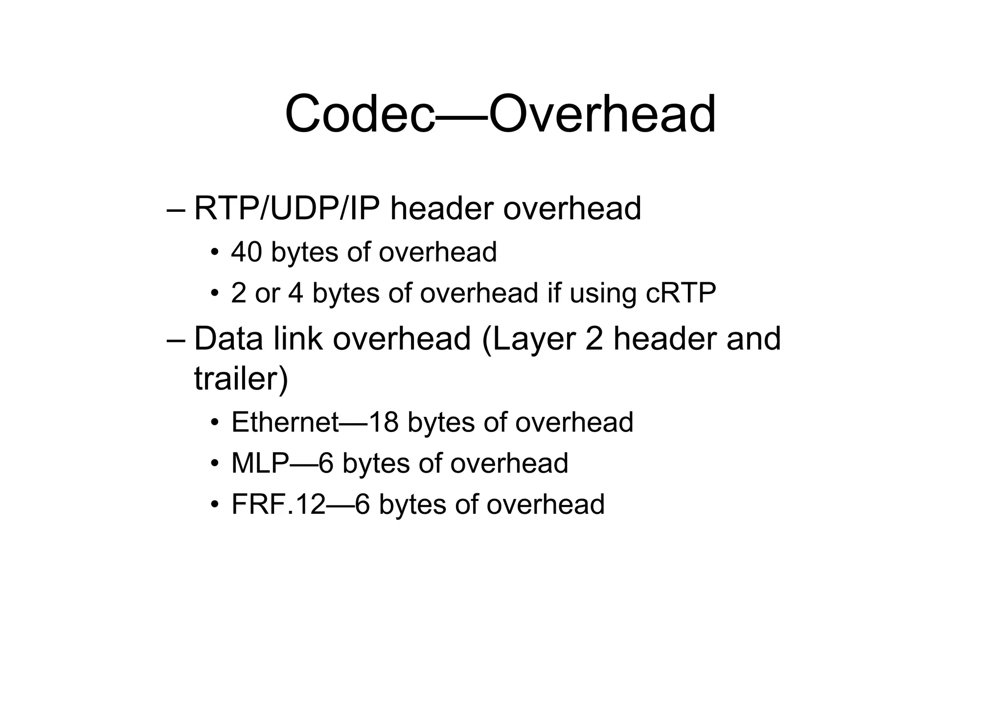
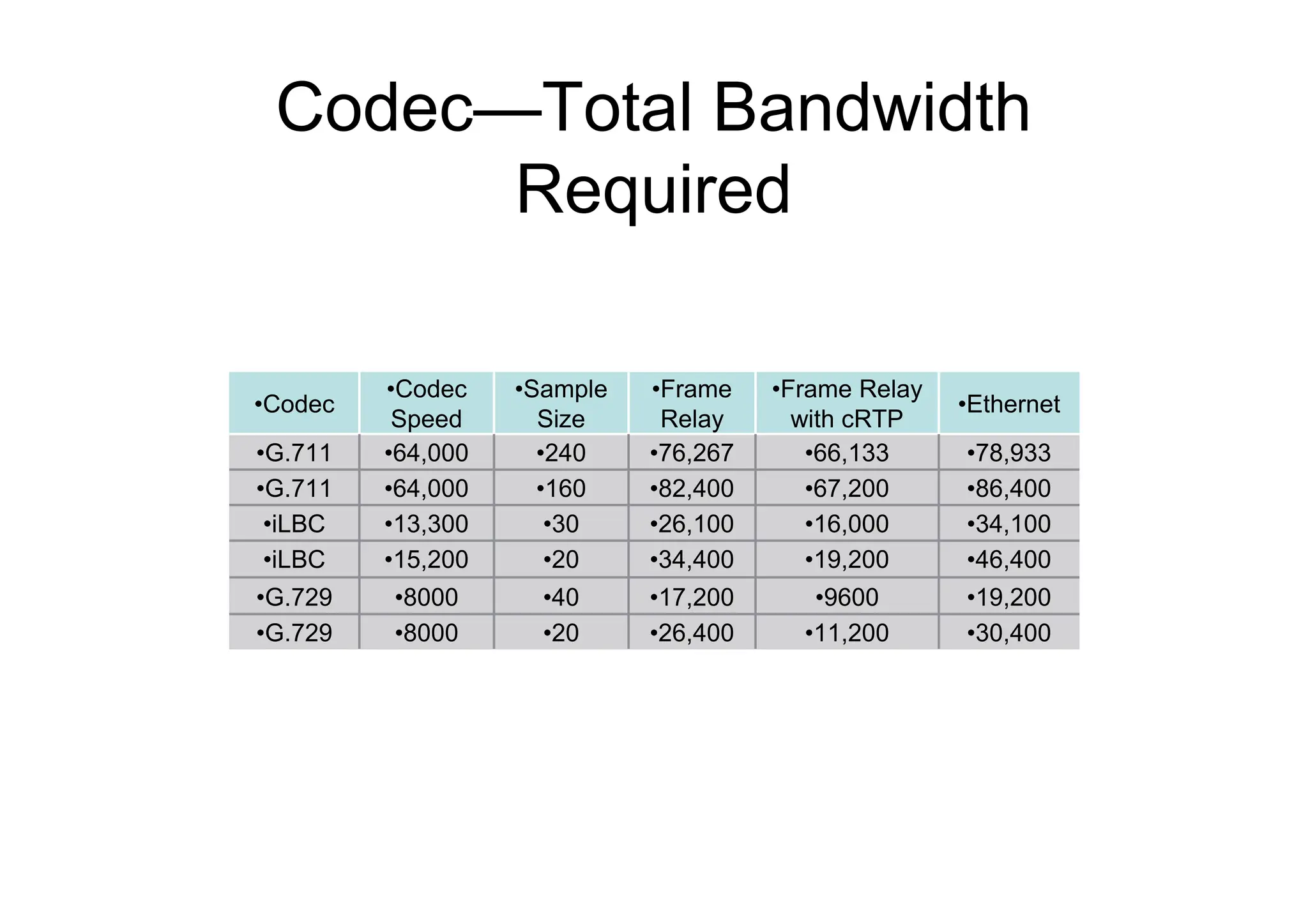
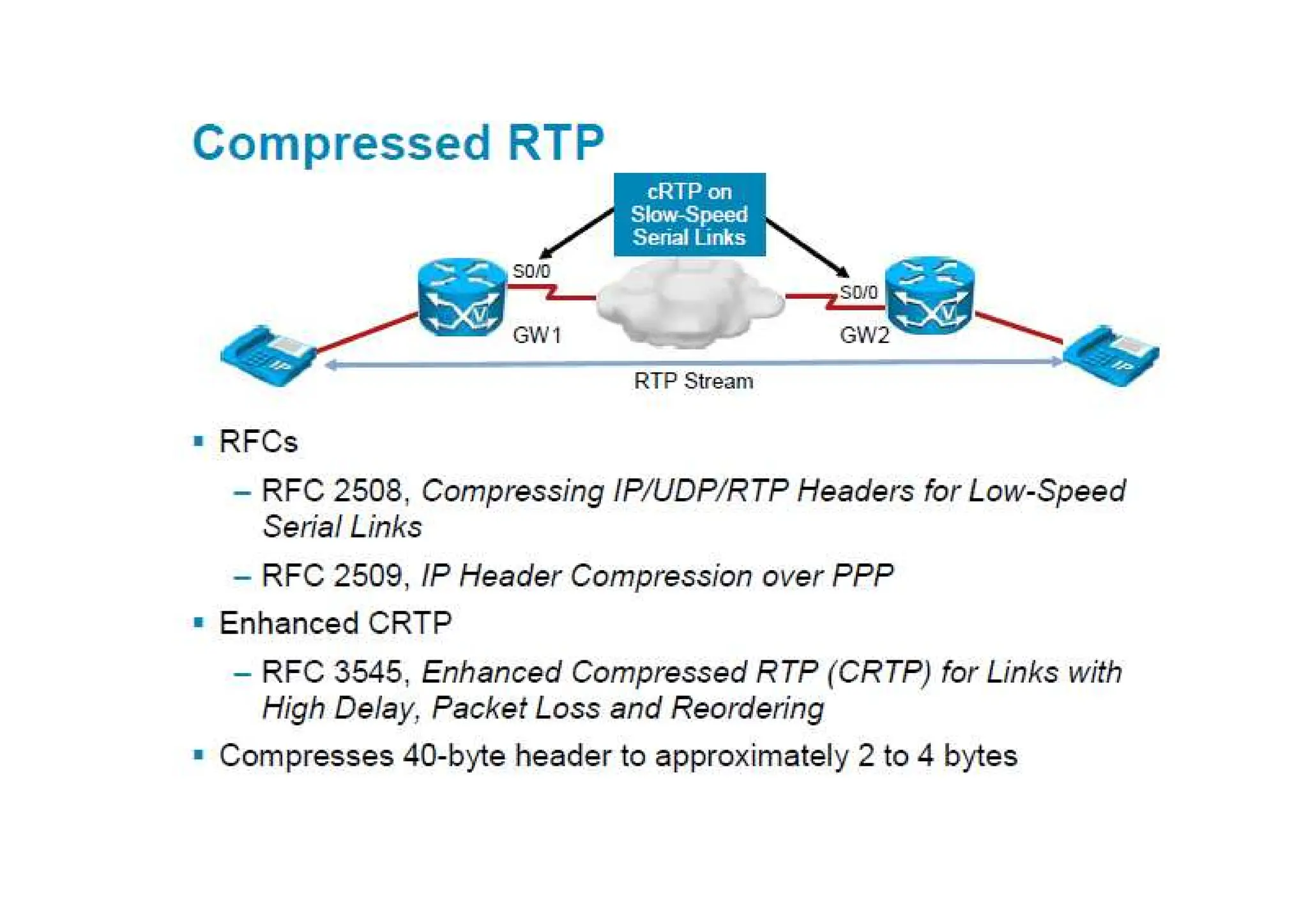
Codec—Overhead
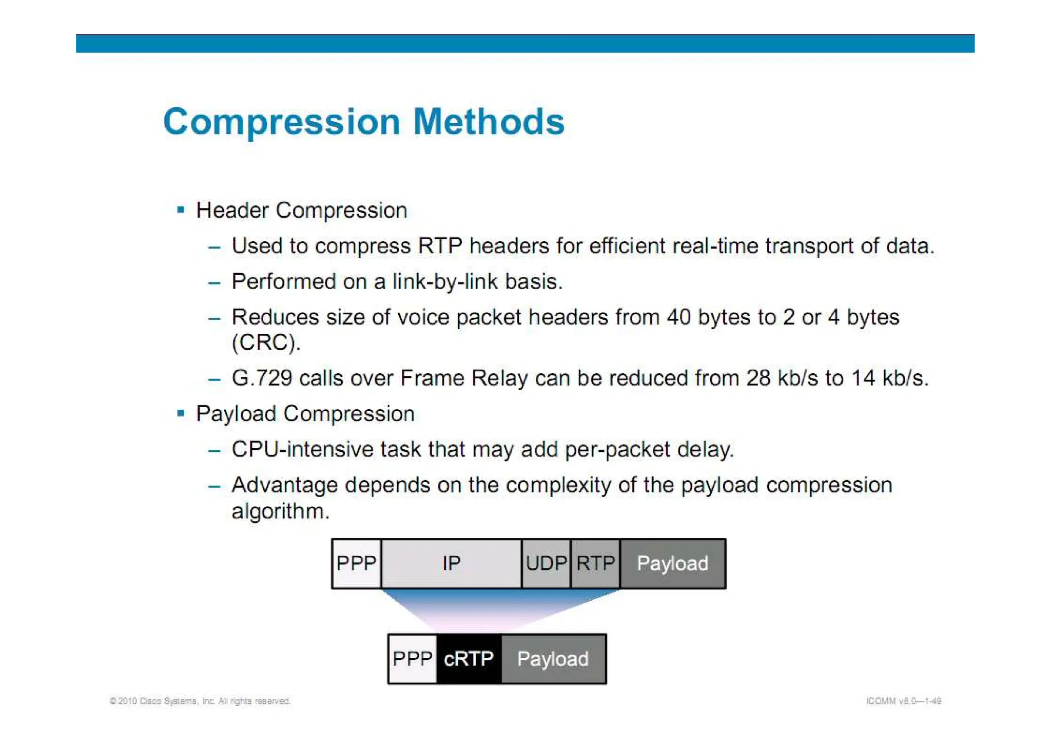
– RTP/UDP/IP headeroverhead
• 40 bytes of overhead
• 2 or 4 bytes of overhead if using cRTP
– Data link overhead (Layer 2 header and
trailer)
• Ethernet—18 bytes of overhead
• MLP—6 bytes of overhead
• FRF.12—6 bytes of overhead
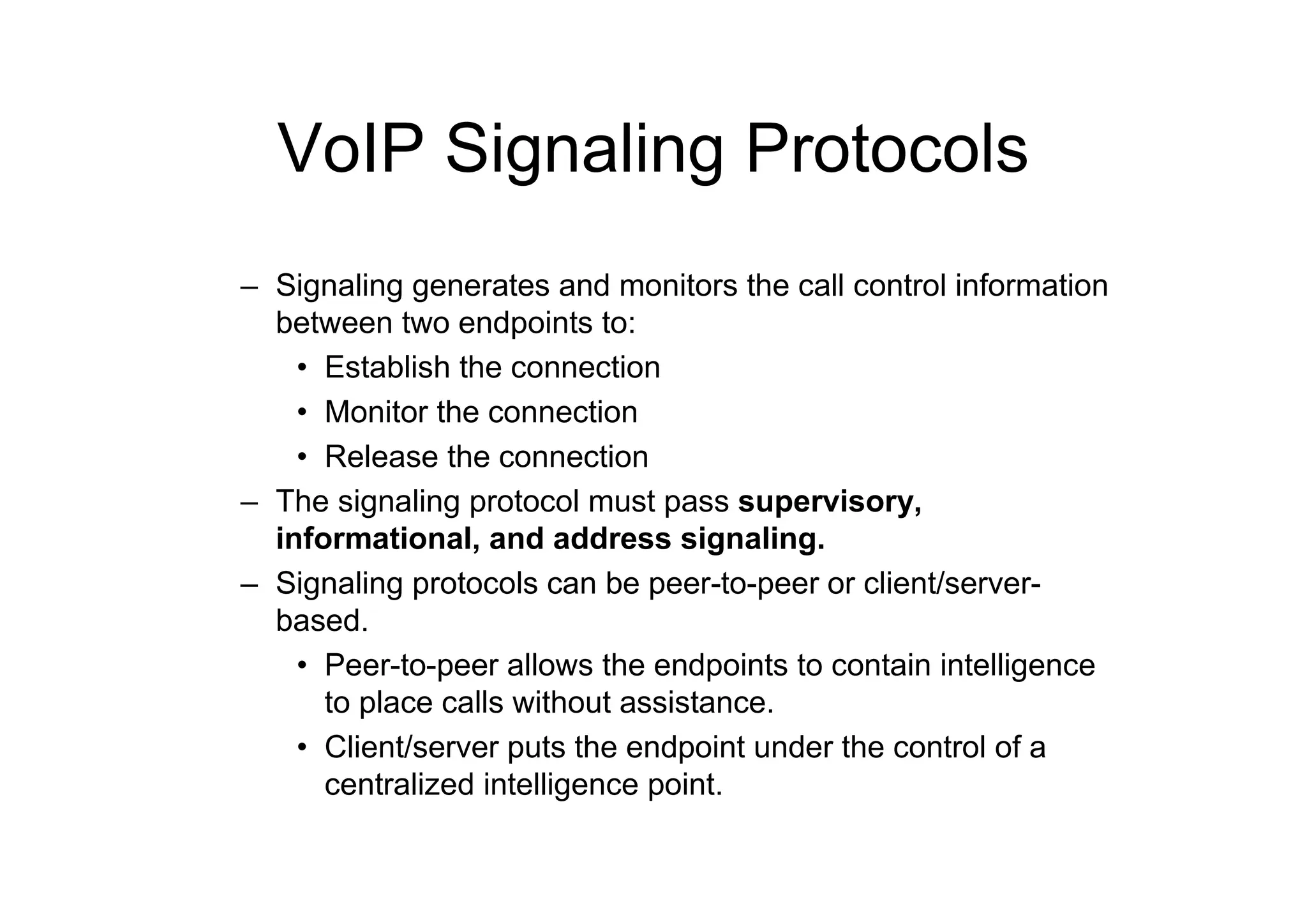
VoIP Signaling Protocols
–Signaling generates and monitors the call control information
between two endpoints to:
• Establish the connection
• Monitor the connection
• Release the connection
– The signaling protocol must pass supervisory,
informational, and address signaling.
– Signaling protocols can be peer-to-peer or client/server-
based.
• Peer-to-peer allows the endpoints to contain intelligence
to place calls without assistance.
• Client/server puts the endpoint under the control of a
centralized intelligence point.
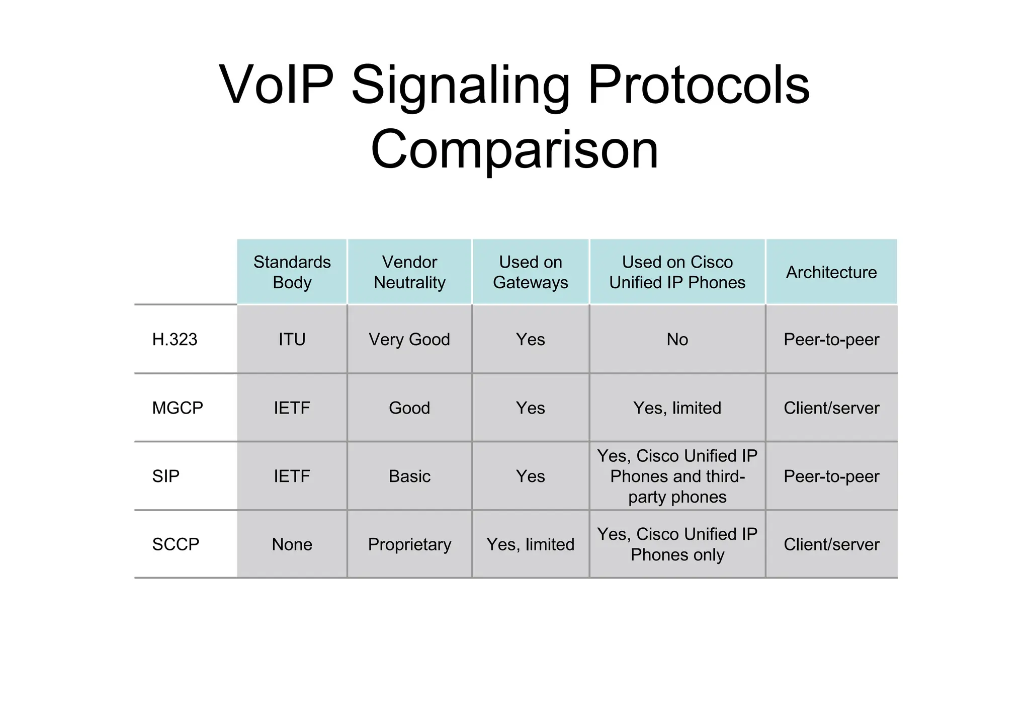
59.
VoIP Signaling Protocols
Comparison
Peer-to-peer
Yes,Cisco Unified IP
Phones and third-
party phones
Yes
Basic
IETF
SIP
Client/server
Yes, Cisco Unified IP
Phones only
Yes, limited
Proprietary
None
SCCP
Client/server
Yes, limited
Yes
Good
IETF
MGCP
Peer-to-peer
No
Yes
Very Good
ITU
H.323
Architecture
Used on Cisco
Unified IP Phones
Used on
Gateways
Vendor
Neutrality
Standards
Body
60.
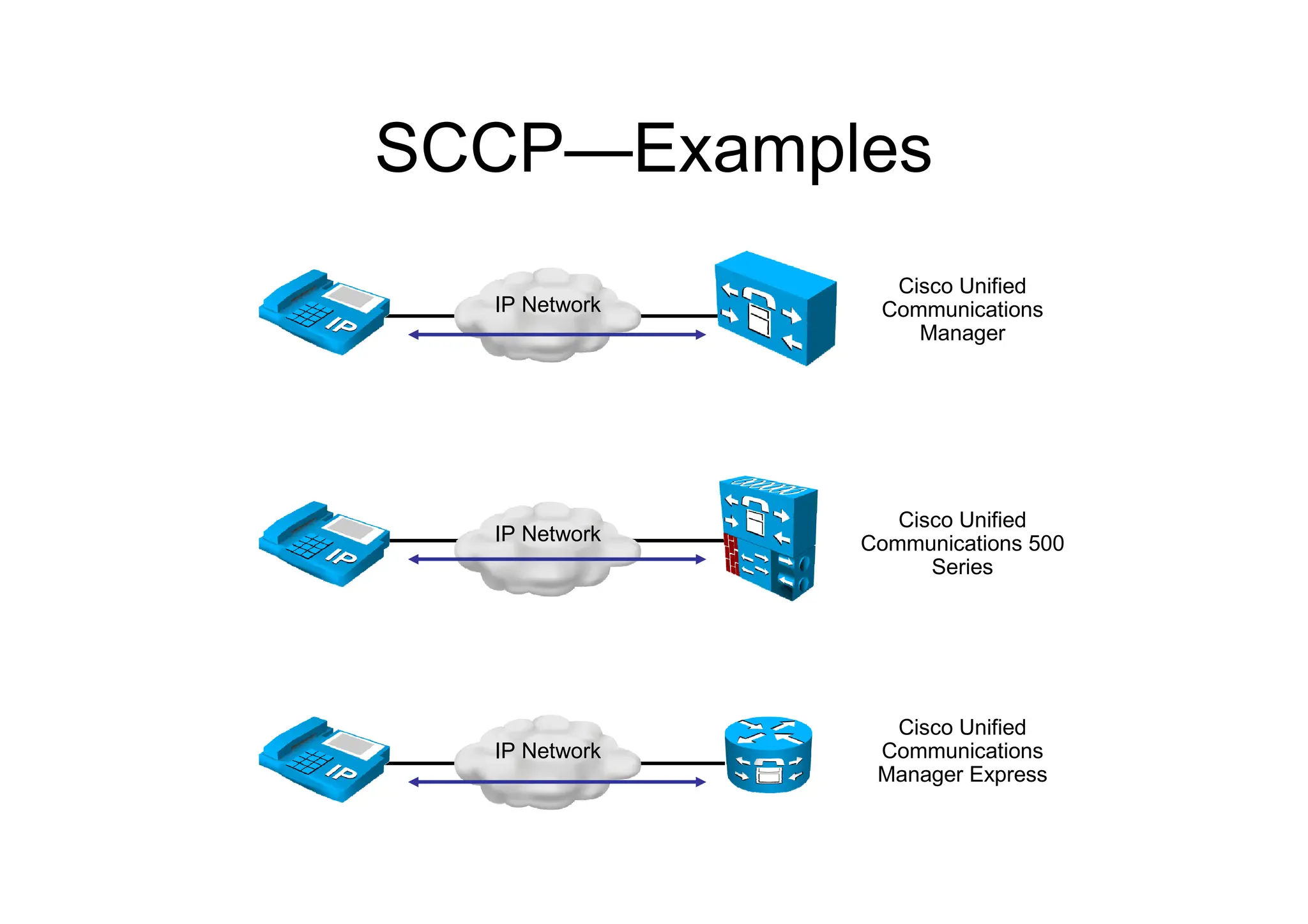
Skinny Client ControlProtocol
– Signaling protocol used between Cisco
Unified Communications call control platforms
and Cisco Unified IP Phones
– Cisco proprietary
– Lightweight protocol
– Client/server protocol
– Used for voice only and video-enabled calls
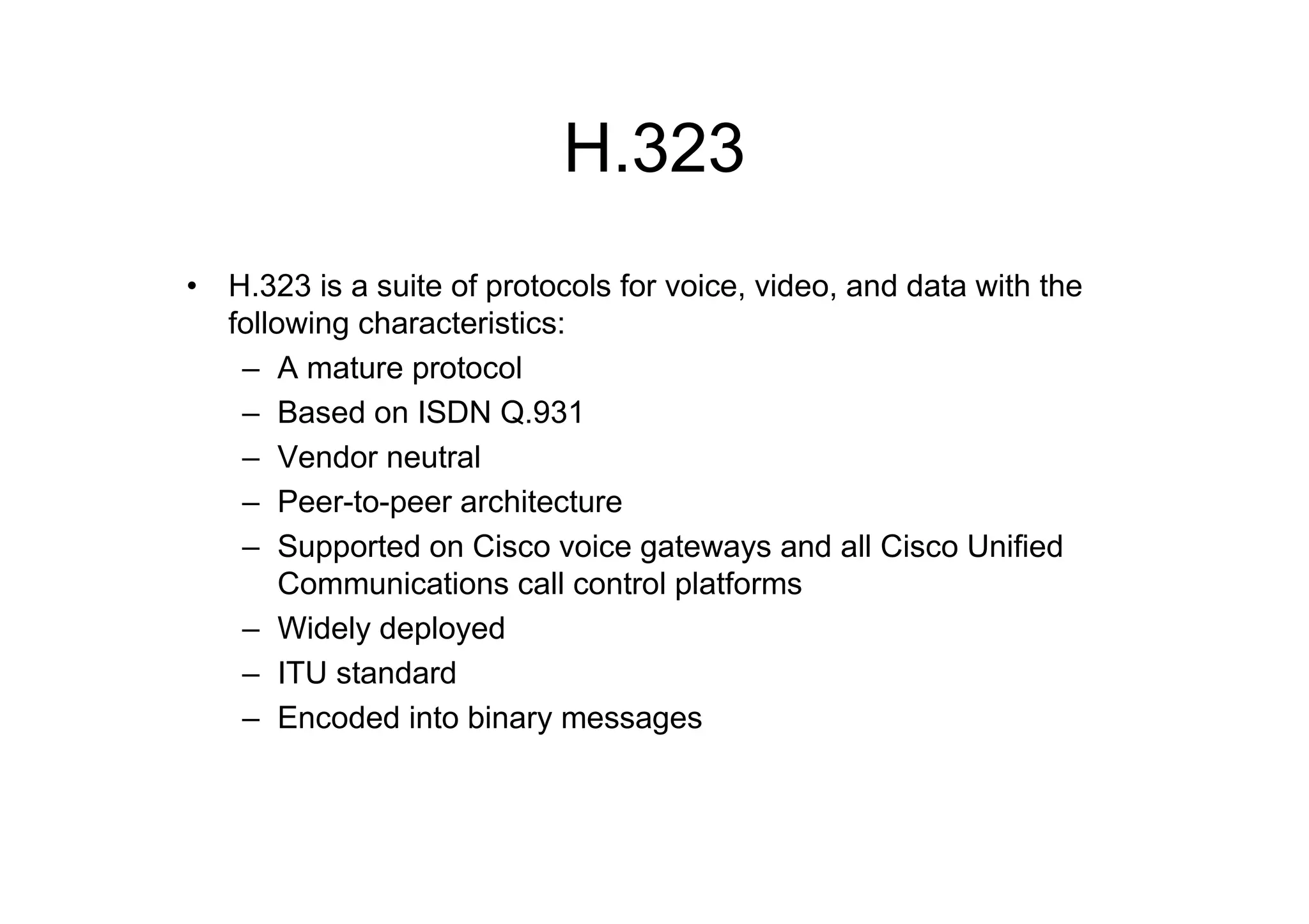
H.323
• H.323 isa suite of protocols for voice, video, and data with the
following characteristics:
– A mature protocol
– Based on ISDN Q.931
– Vendor neutral
– Peer-to-peer architecture
– Supported on Cisco voice gateways and all Cisco Unified
Communications call control platforms
– Widely deployed
– ITU standard
– Encoded into binary messages
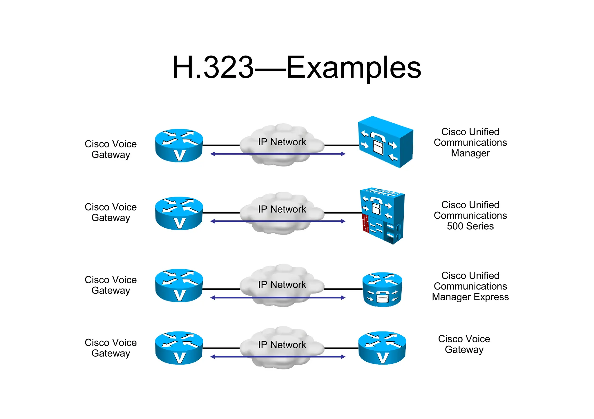
63.
H.323—Examples
IP Network
Cisco Unified
Communications
Manager
CiscoVoice
Gateway
IP Network Cisco Unified
Communications
500 Series
Cisco Voice
Gateway
IP Network
Cisco Unified
Communications
Manager Express
Cisco Voice
Gateway
IP Network
Cisco Voice
Gateway
Cisco Voice
Gateway
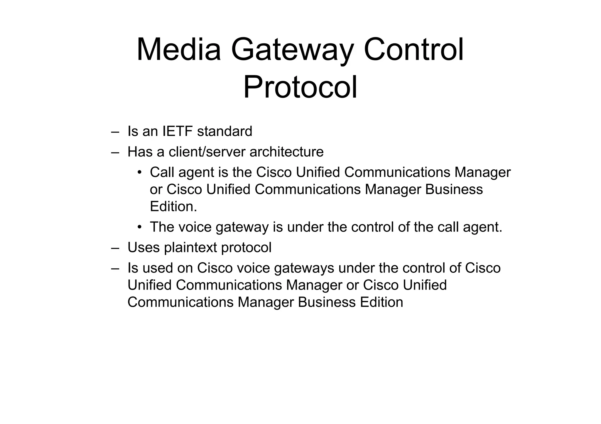
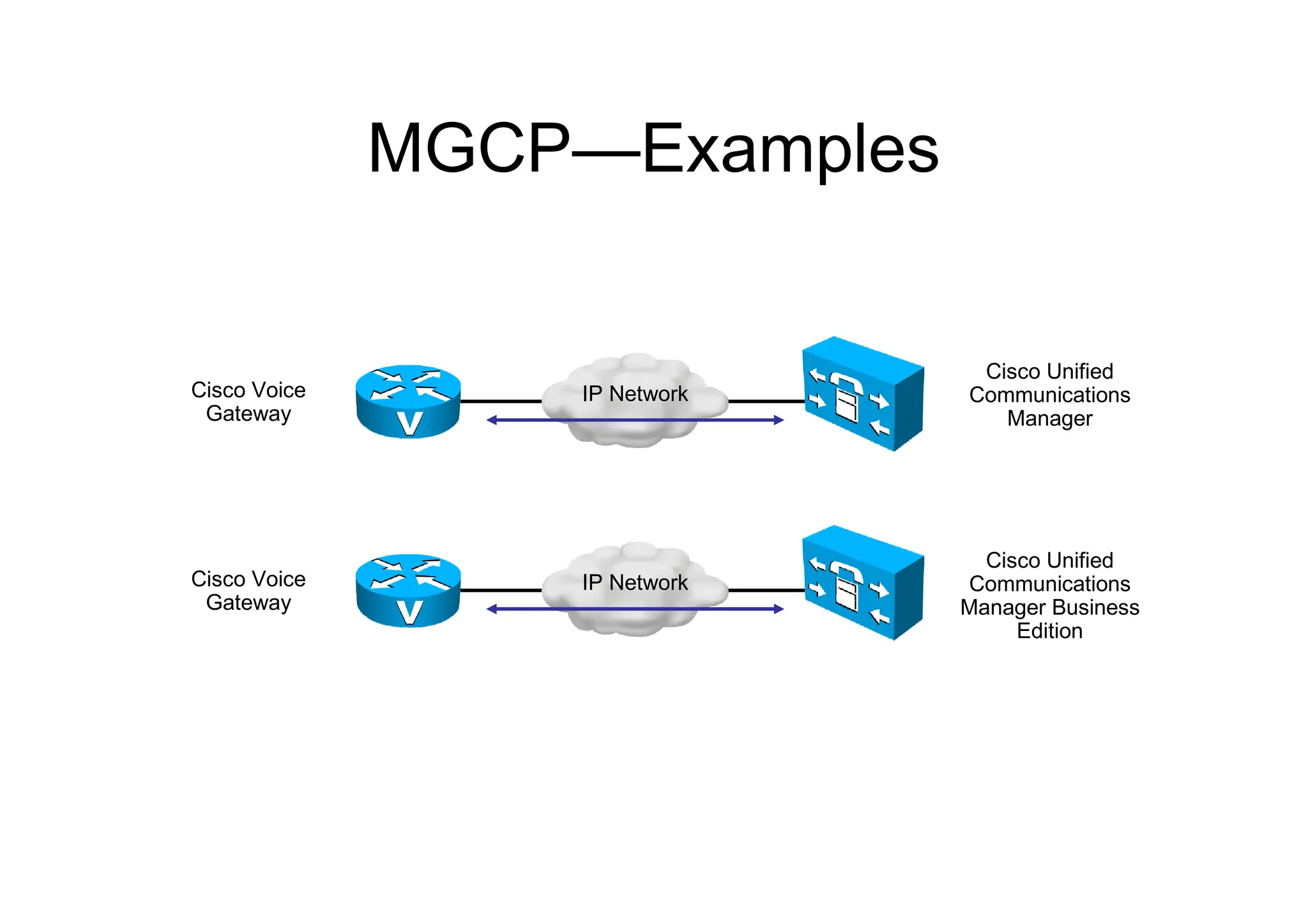
64.
Media Gateway Control
Protocol
–Is an IETF standard
– Has a client/server architecture
• Call agent is the Cisco Unified Communications Manager
or Cisco Unified Communications Manager Business
Edition.
• The voice gateway is under the control of the call agent.
– Uses plaintext protocol
– Is used on Cisco voice gateways under the control of Cisco
Unified Communications Manager or Cisco Unified
Communications Manager Business Edition
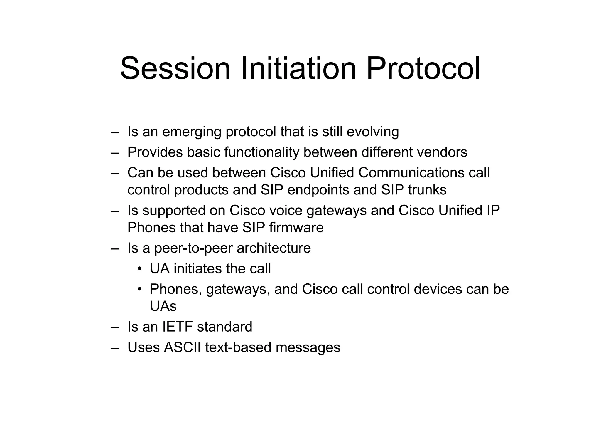
Session Initiation Protocol
–Is an emerging protocol that is still evolving
– Provides basic functionality between different vendors
– Can be used between Cisco Unified Communications call
control products and SIP endpoints and SIP trunks
– Is supported on Cisco voice gateways and Cisco Unified IP
Phones that have SIP firmware
– Is a peer-to-peer architecture
• UA initiates the call
• Phones, gateways, and Cisco call control devices can be
UAs
– Is an IETF standard
– Uses ASCII text-based messages
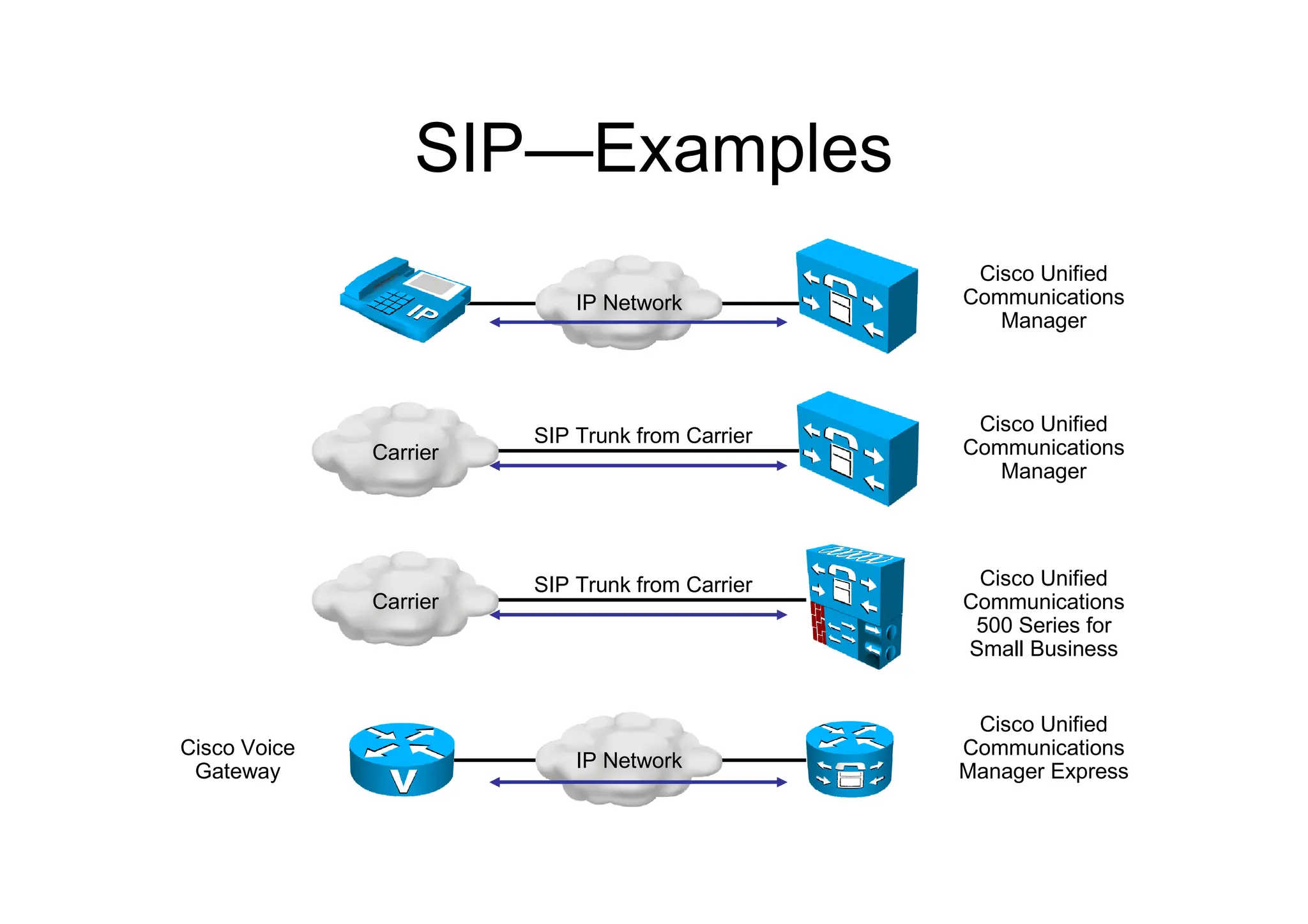
67.
SIP—Examples
SIP Trunk fromCarrier
Carrier
Cisco Unified
Communications
Manager
IP Network
Cisco Unified
Communications
Manager
IP Network
Cisco Unified
Communications
Manager Express
Cisco Voice
Gateway
SIP Trunk from Carrier
Carrier
Cisco Unified
Communications
500 Series for
Small Business
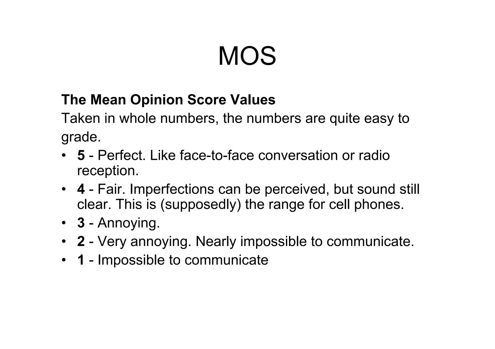
MOS
The Mean OpinionScore Values
Taken in whole numbers, the numbers are quite easy to
grade.
• 5 - Perfect. Like face-to-face conversation or radio
reception.
• 4 - Fair. Imperfections can be perceived, but sound still
clear. This is (supposedly) the range for cell phones.
• 3 - Annoying.
• 2 - Very annoying. Nearly impossible to communicate.
• 1 - Impossible to communicate
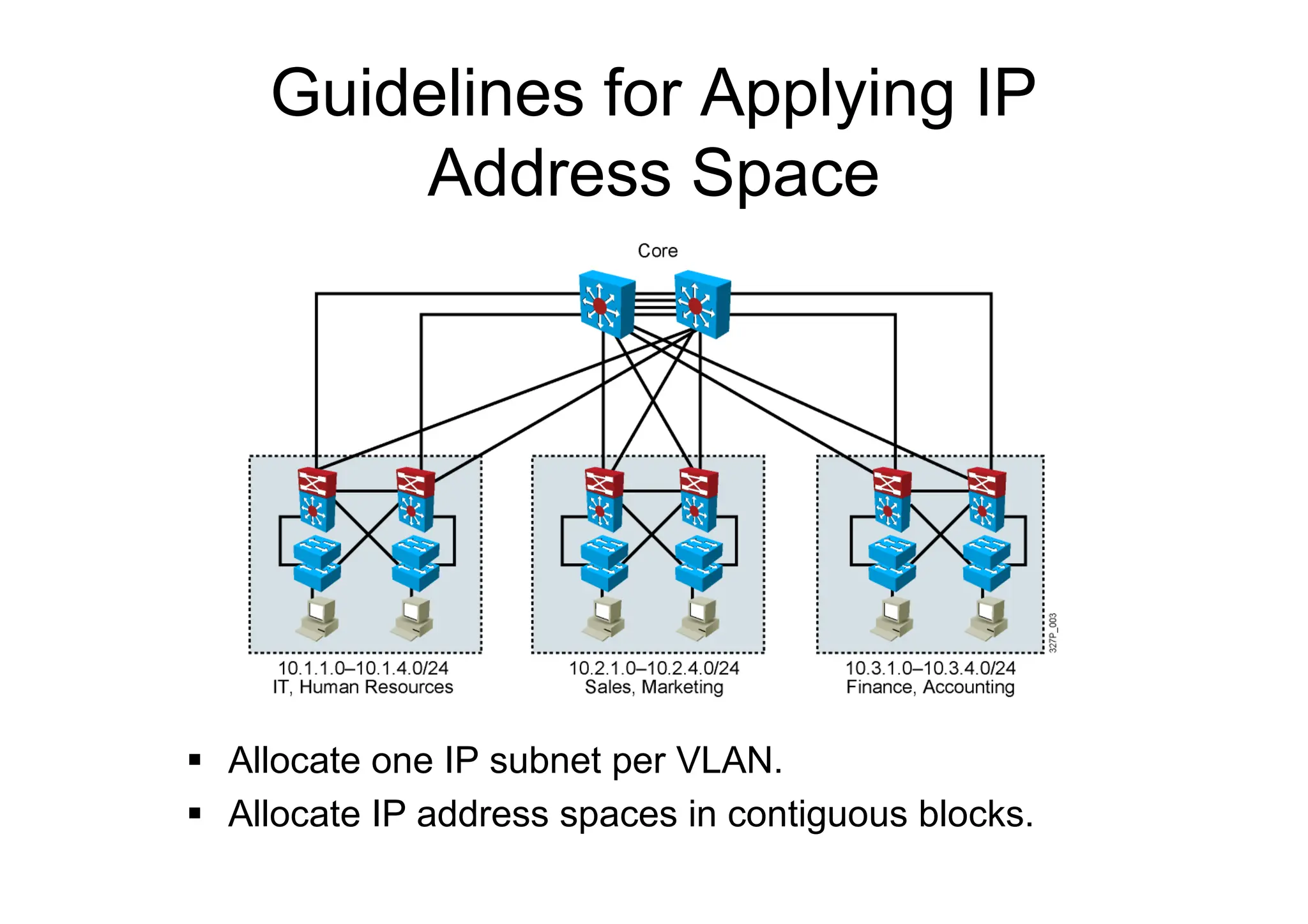
Guidelines for ApplyingIP
Address Space
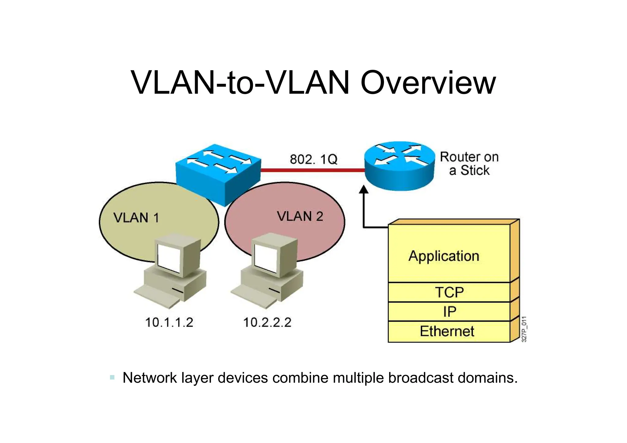
Allocate one IP subnet per VLAN.
Allocate IP address spaces in contiguous blocks.
94.
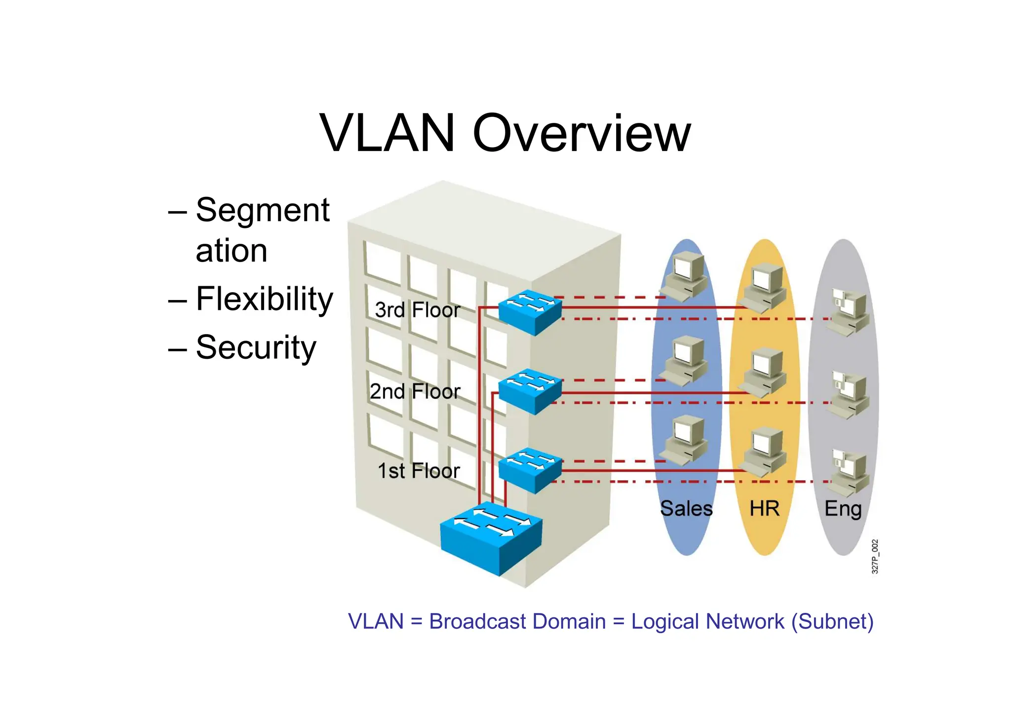
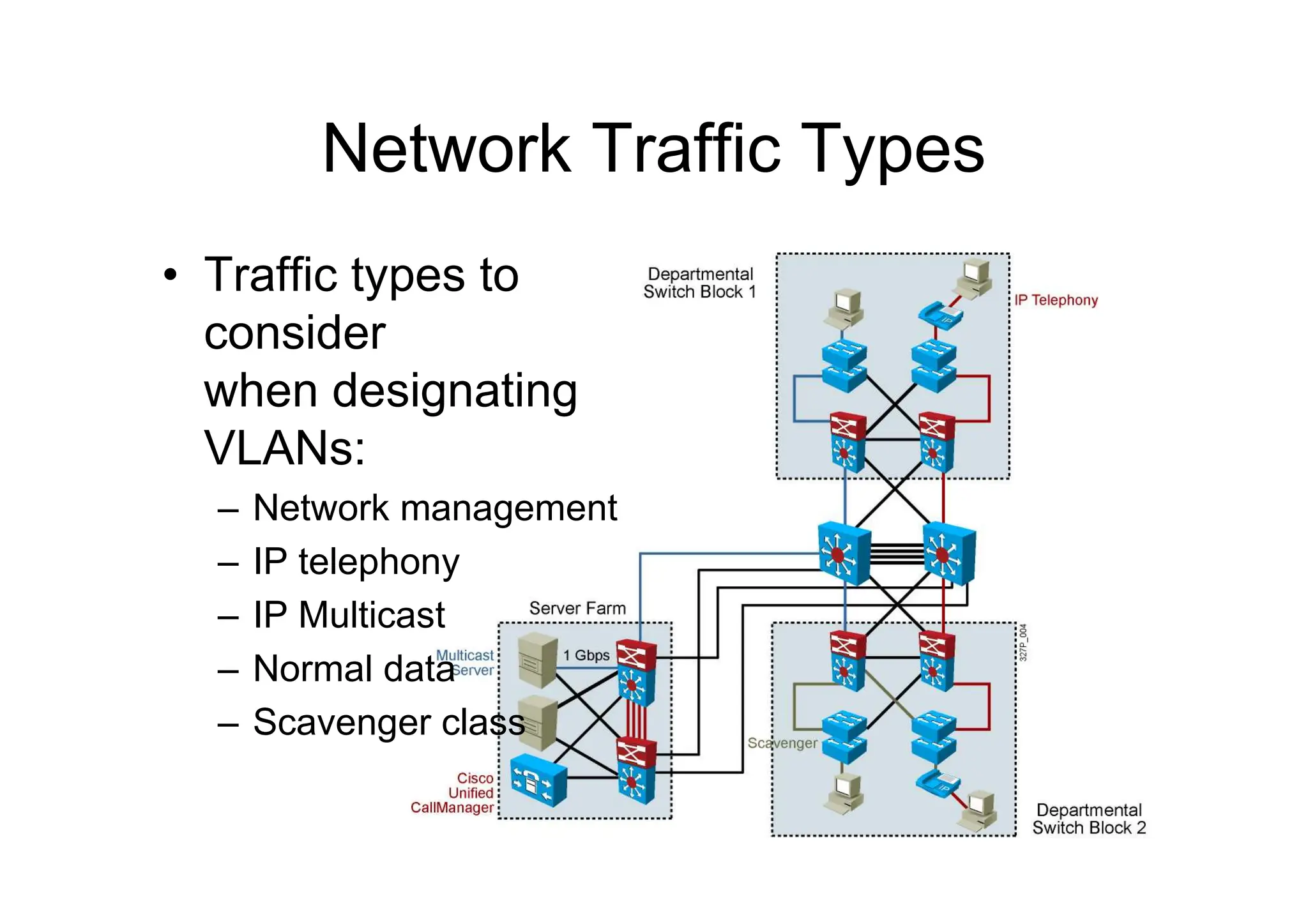
Network Traffic Types
•Traffic types to
consider
when designating
VLANs:
– Network management
– IP telephony
– IP Multicast
– Normal data
– Scavenger class
95.
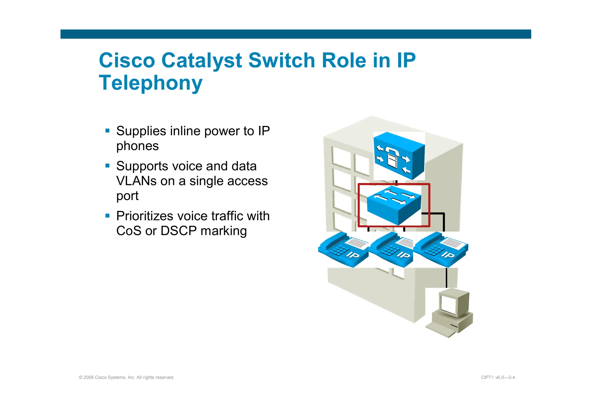
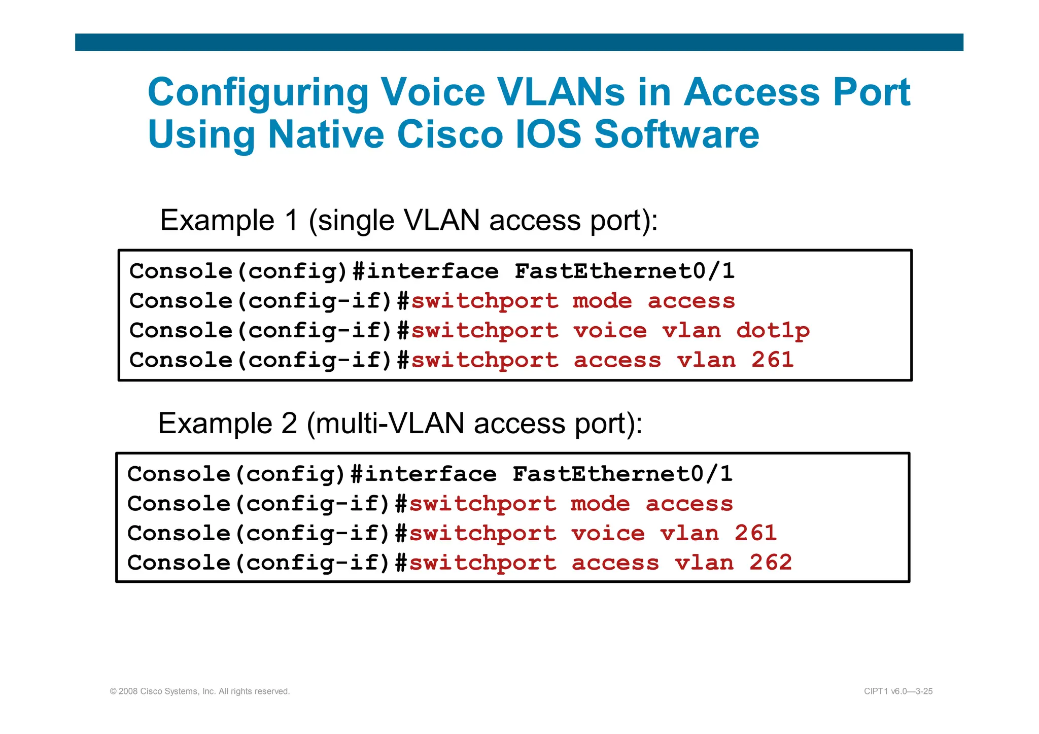
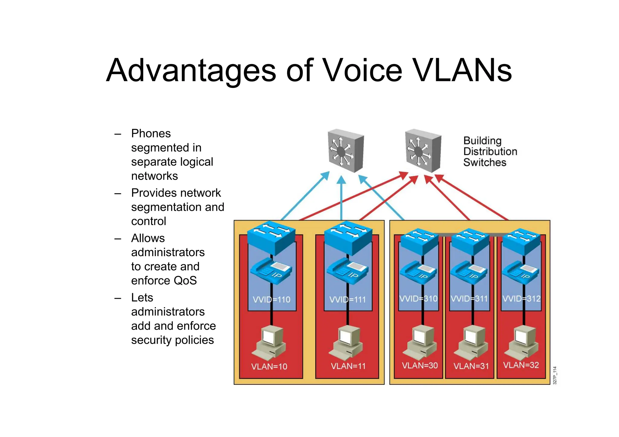
Advantages of VoiceVLANs
– Phones
segmented in
separate logical
networks
– Provides network
segmentation and
control
– Allows
administrators
to create and
enforce QoS
– Lets
administrators
add and enforce
security policies
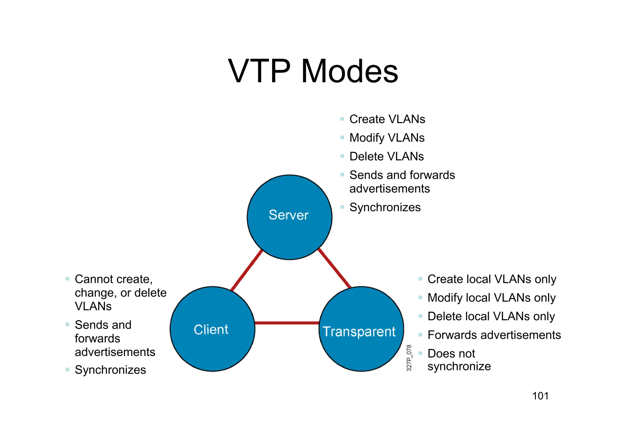
101
Cannot create,
change,or delete
VLANs
Sends and
forwards
advertisements
Synchronizes
Create VLANs
Modify VLANs
Delete VLANs
Sends and forwards
advertisements
Synchronizes
Create local VLANs only
Modify local VLANs only
Delete local VLANs only
Forwards advertisements
Does not
synchronize
VTP Modes
102.
SwitchX# configure terminal
SwitchX(config)#vtp mode [ server | client | transparent ]
SwitchX(config)# vtp domain domain-name
SwitchX(config)# vtp password password
SwitchX(config)# end
Creating a VTP Domain
103.
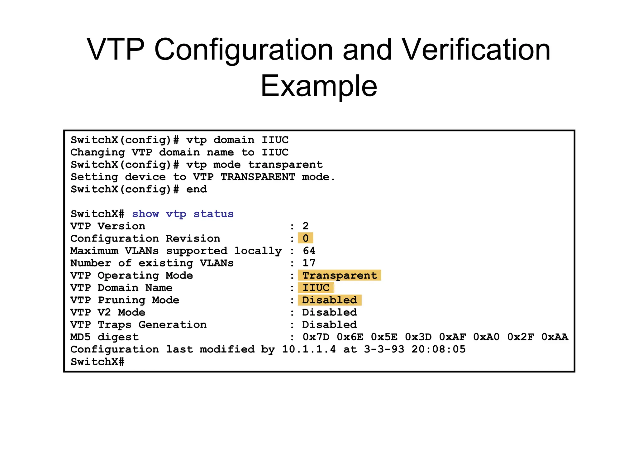
SwitchX(config)# vtp domainIIUC
Changing VTP domain name to IIUC
SwitchX(config)# vtp mode transparent
Setting device to VTP TRANSPARENT mode.
SwitchX(config)# end
SwitchX# show vtp status
VTP Version : 2
Configuration Revision : 0
Maximum VLANs supported locally : 64
Number of existing VLANs : 17
VTP Operating Mode : Transparent
VTP Domain Name : IIUC
VTP Pruning Mode : Disabled
VTP V2 Mode : Disabled
VTP Traps Generation : Disabled
MD5 digest : 0x7D 0x6E 0x5E 0x3D 0xAF 0xA0 0x2F 0xAA
Configuration last modified by 10.1.1.4 at 3-3-93 20:08:05
SwitchX#
VTP Configuration and Verification
Example
104.
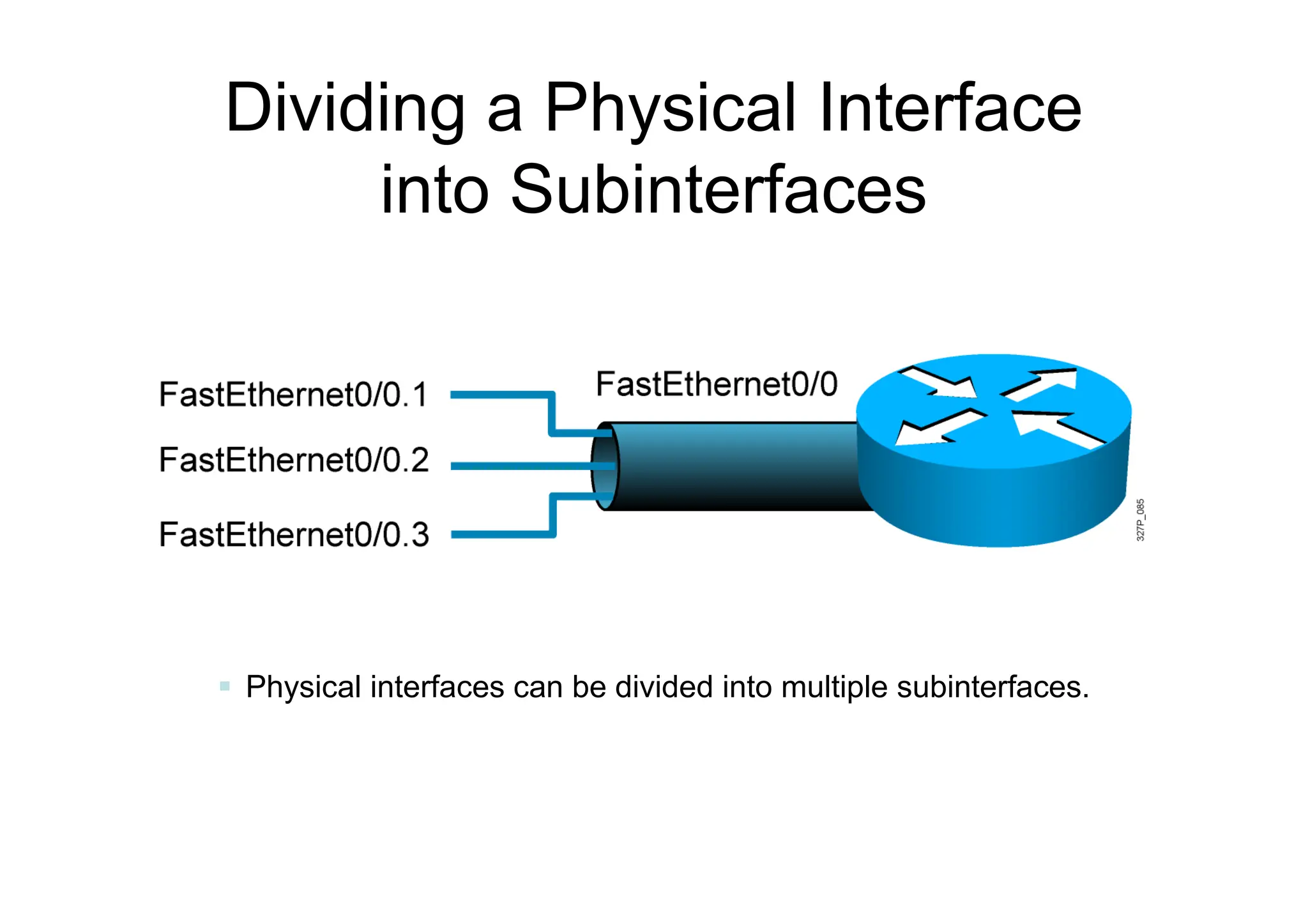
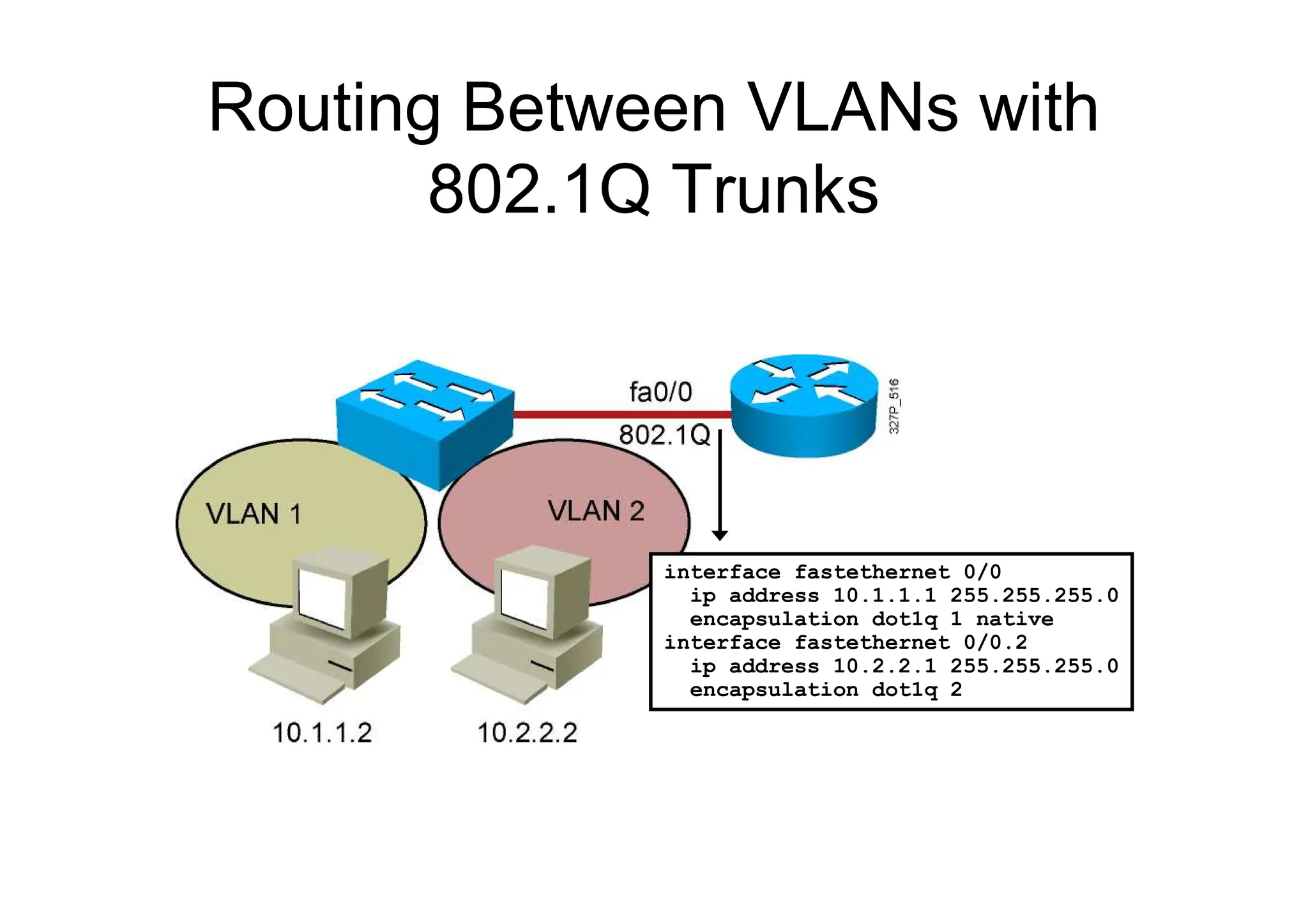
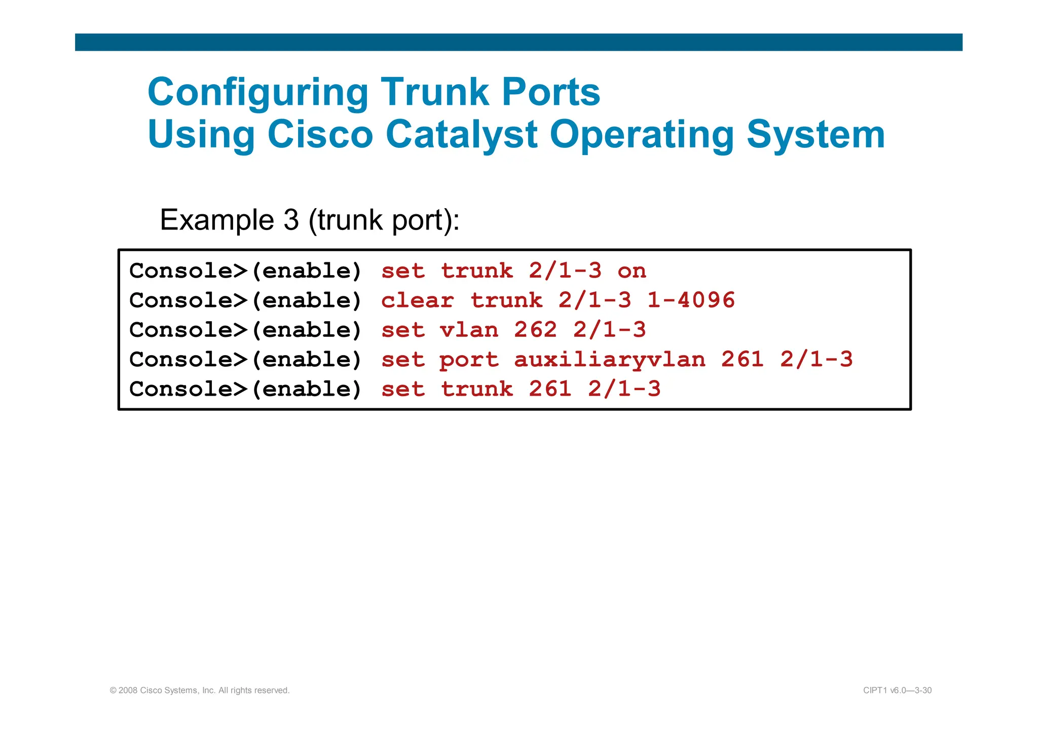
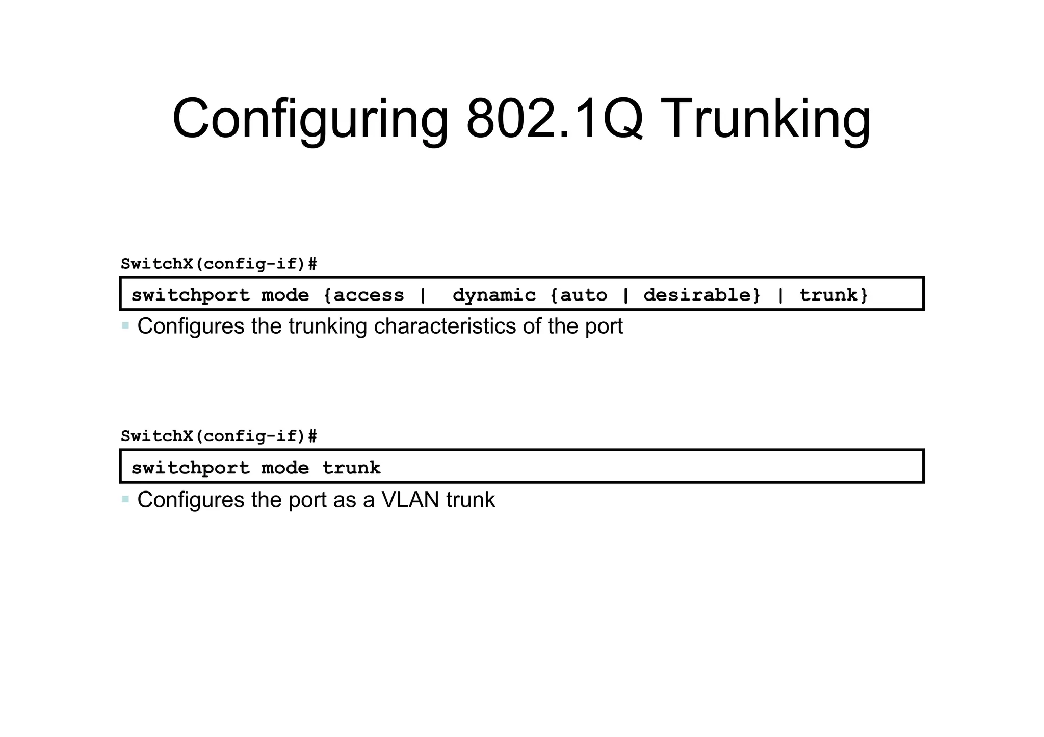
Configuring 802.1Q Trunking
Configures the port as a VLAN trunk
SwitchX(config-if)#
switchport mode trunk
switchport mode {access | dynamic {auto | desirable} | trunk}
SwitchX(config-if)#
Configures the trunking characteristics of the port
105.
105
SwitchX# show interfacesfa0/11 trunk
Port Mode Encapsulation Status Native vlan
Fa0/11 desirable 802.1q trunking 1
Port Vlans allowed on trunk
Fa0/11 1-4094
Port Vlans allowed and active in management domain
Fa0/11 1-13
SwitchX# show interfaces fa0/11 switchport
Name: Fa0/11
Switchport: Enabled
Administrative Mode: trunk
Operational Mode: down
Administrative Trunking Encapsulation: dot1q
Negotiation of Trunking: On
Access Mode VLAN: 1 (default)
Trunking Native Mode VLAN: 1 (default)
. . .
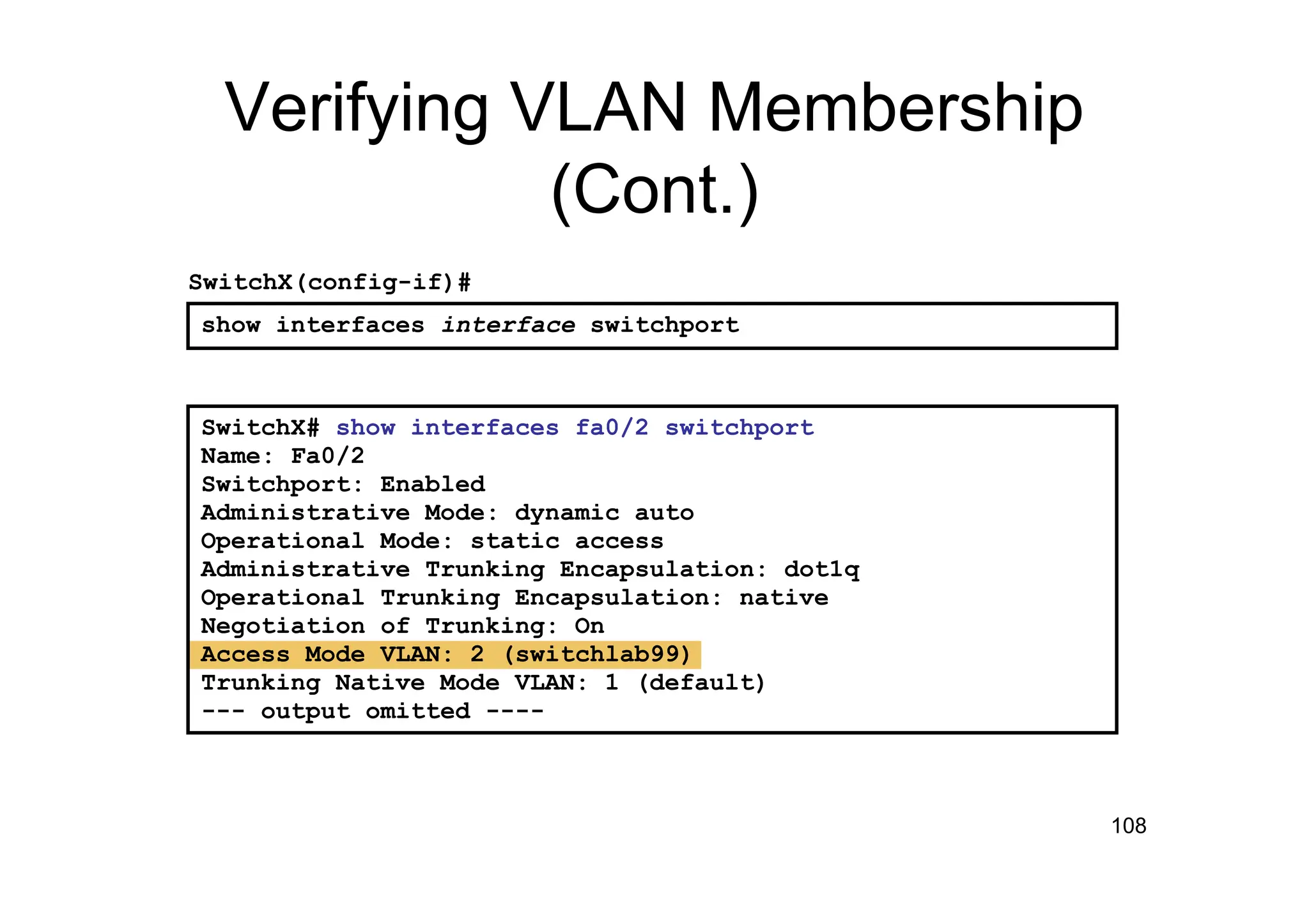
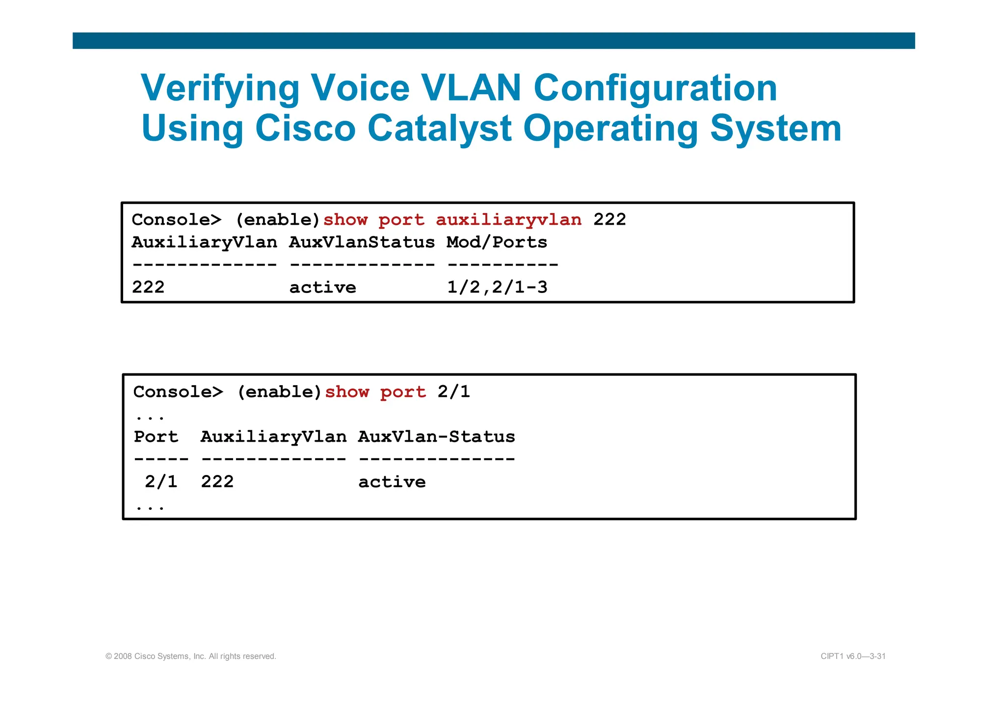
Verifying a Trunk
SwitchX# show interfaces interface [switchport | trunk]
106.
106
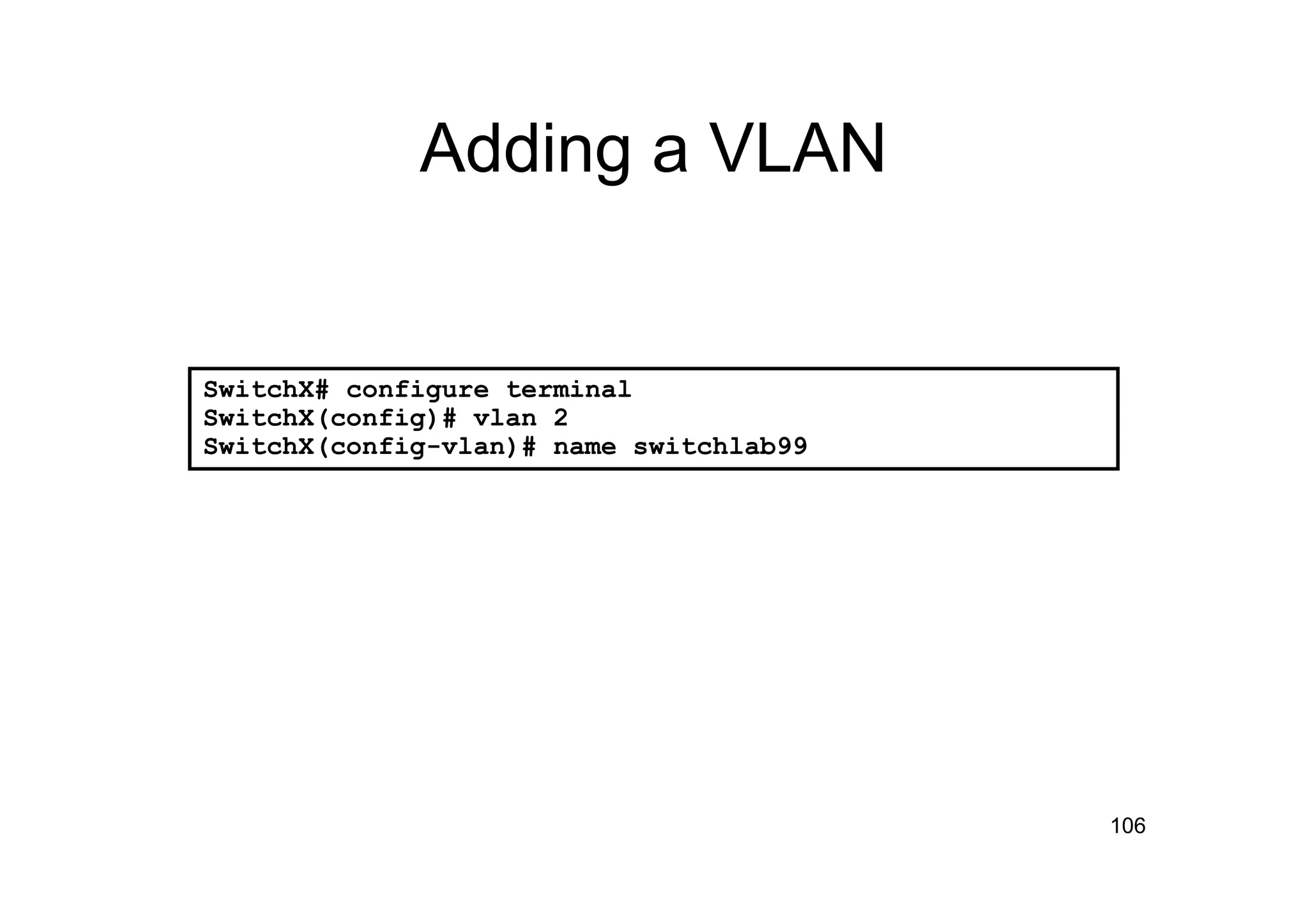
Adding a VLAN
SwitchX#configure terminal
SwitchX(config)# vlan 2
SwitchX(config-vlan)# name switchlab99
107.
107
Assigning Switch Portsto a
VLAN
SwitchX# configure terminal
SwitchX(config)# interface range fastethernet 0/2 - 4
SwitchX(config-if)# switchport access vlan 2
SwitchX# show vlan
VLAN Name Status Ports
---- -------------------------------- --------- ----------------------
1 default active Fa0/1
2 switchlab99 active Fa0/2, Fa0/3, Fa0/4
switchport access [vlan vlan# | dynamic]
SwitchX(config-if)#
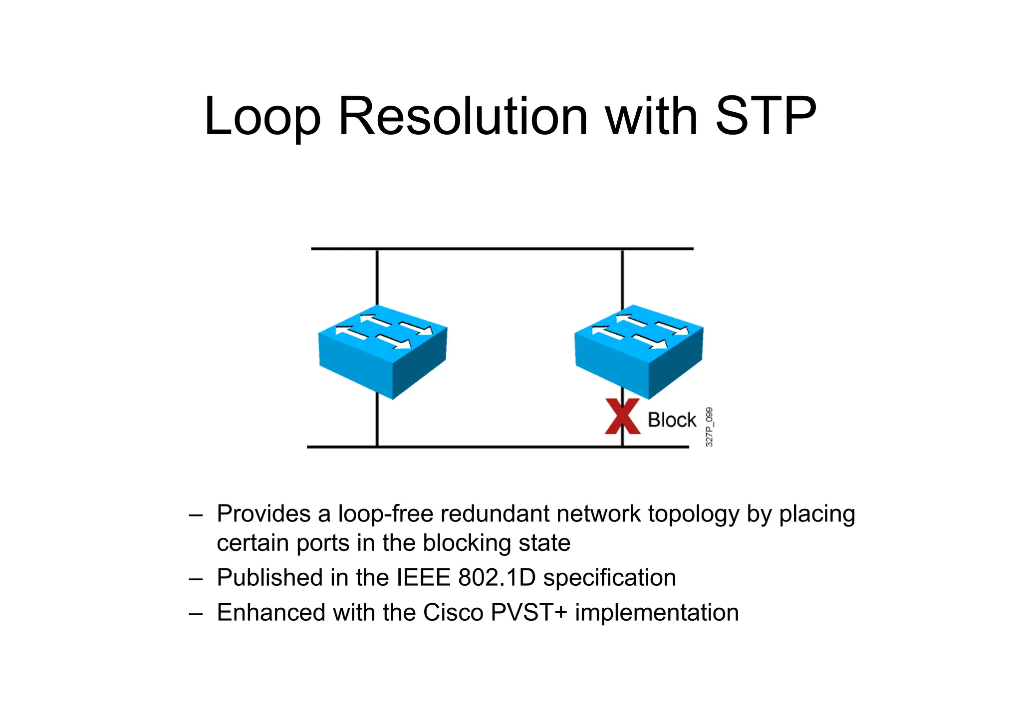
Loop Resolution withSTP
– Provides a loop-free redundant network topology by placing
certain ports in the blocking state
– Published in the IEEE 802.1D specification
– Enhanced with the Cisco PVST+ implementation
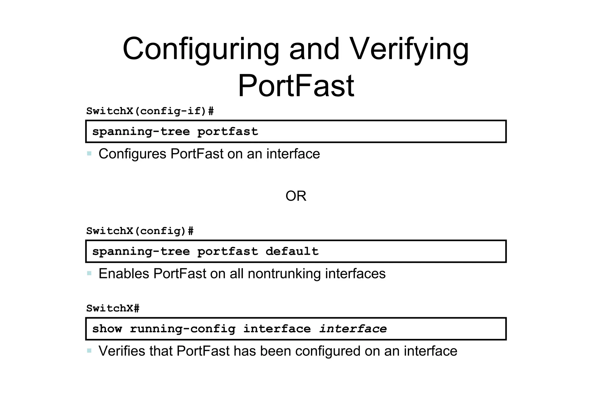
Configuring and Verifying
PortFast
spanning-treeportfast
SwitchX(config-if)#
Configures PortFast on an interface
spanning-tree portfast default
SwitchX(config)#
Enables PortFast on all nontrunking interfaces
show running-config interface interface
SwitchX#
Verifies that PortFast has been configured on an interface
OR


![SwitchX# configure terminal
SwitchX(config)# vtp mode [ server | client | transparent ]
SwitchX(config)# vtp domain domain-name
SwitchX(config)# vtp password password
SwitchX(config)# end
Creating a VTP Domain](https://image.slidesharecdn.com/1-voipfundamentals-250319191126-22116e40/75/1-voip-fundamentals-engineering-pdf-102-2048.jpg)
![105
SwitchX# show interfaces fa0/11 trunk
Port Mode Encapsulation Status Native vlan
Fa0/11 desirable 802.1q trunking 1
Port Vlans allowed on trunk
Fa0/11 1-4094
Port Vlans allowed and active in management domain
Fa0/11 1-13
SwitchX# show interfaces fa0/11 switchport
Name: Fa0/11
Switchport: Enabled
Administrative Mode: trunk
Operational Mode: down
Administrative Trunking Encapsulation: dot1q
Negotiation of Trunking: On
Access Mode VLAN: 1 (default)
Trunking Native Mode VLAN: 1 (default)
. . .
Verifying a Trunk
SwitchX# show interfaces interface [switchport | trunk]](https://image.slidesharecdn.com/1-voipfundamentals-250319191126-22116e40/75/1-voip-fundamentals-engineering-pdf-105-2048.jpg)
![107
Assigning Switch Ports to a
VLAN
SwitchX# configure terminal
SwitchX(config)# interface range fastethernet 0/2 - 4
SwitchX(config-if)# switchport access vlan 2
SwitchX# show vlan
VLAN Name Status Ports
---- -------------------------------- --------- ----------------------
1 default active Fa0/1
2 switchlab99 active Fa0/2, Fa0/3, Fa0/4
switchport access [vlan vlan# | dynamic]
SwitchX(config-if)#](https://image.slidesharecdn.com/1-voipfundamentals-250319191126-22116e40/75/1-voip-fundamentals-engineering-pdf-107-2048.jpg)