The document provides an overview of fundamental computing concepts, focusing on data structures, algorithms, programming languages, and flowcharting. It defines various data structures such as arrays, linked lists, stacks, and trees, along with their properties and traversal methods. Additionally, it discusses the nature of programming languages, categorizing them based on readability and providing examples of high-level languages.

![Computing Concepts. Prepared by: Engr. Nathaniel M. Cabansay 6
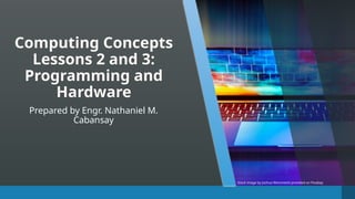
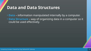
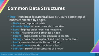
Common Data Structures
• Array – holds items of the same type [1].
• Element – an item stored in the array.
• Index – location of an element in an array. It is used to identify the
element. The index of the first element of an array is typically 0.
• Linked List / List – a data structure that decides the
arrangement of data with a pointer (reference to the
memory address of data) to the next element with the
option to pointer to the previous one [1].](https://image.slidesharecdn.com/0203algorithmsandprogrammingcomputercomponents-250120154408-23358de7/85/02_03_Algorithms-and-Programming_Computer-Components-pptx-6-320.jpg)
![Computing Concepts. Prepared by: Engr. Nathaniel M. Cabansay 8
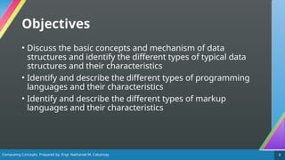
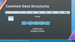
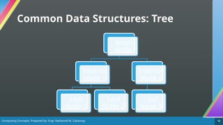
Common Data Structures
• Stack – follows the Last In, First Out (LIFO) principle.
Elements are added and removed from the same end,
known as the top [2].
• Push – insert an item on top of the stack.
• Pop – remove an item from the top of the stack.
• Queue – follows the First In, First Out (FIFO) principle.
Elements are added at one end called the rear, and removed
from the other end called the front [2].
• Enqueue – insert an item into the rear of the queue.
• Dequeue – remove an item from the front of the queue.](https://image.slidesharecdn.com/0203algorithmsandprogrammingcomputercomponents-250120154408-23358de7/85/02_03_Algorithms-and-Programming_Computer-Components-pptx-8-320.jpg)
![Computing Concepts. Prepared by: Engr. Nathaniel M. Cabansay 13
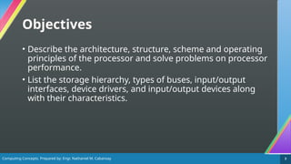
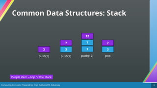
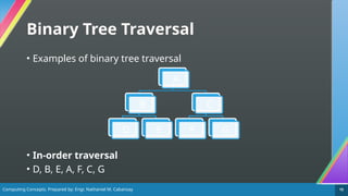
Common Data Structures
• Binary Tree – a type of tree which has up to two children.
• Binary trees can be traversed in many ways [3]:
• Pre-order traversal: Root, left, right
• In-order traversal: Left, root, right
• Post-order traversal: Left, right, root
• Level order traversal: All nodes on the same level are traversed
from left to right.](https://image.slidesharecdn.com/0203algorithmsandprogrammingcomputercomponents-250120154408-23358de7/85/02_03_Algorithms-and-Programming_Computer-Components-pptx-13-320.jpg)


![Computing Concepts. Prepared by: Engr. Nathaniel M. Cabansay 19
What is an Algorithm?
• Algorithm – a step-by-step way of getting something done
[4], just like computer programs or processes.](https://image.slidesharecdn.com/0203algorithmsandprogrammingcomputercomponents-250120154408-23358de7/85/02_03_Algorithms-and-Programming_Computer-Components-pptx-19-320.jpg)
![Computing Concepts. Prepared by: Engr. Nathaniel M. Cabansay 20
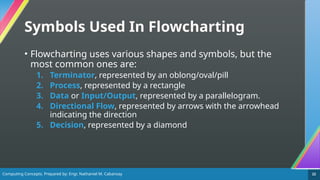
What is a Flowchart?
• Flowchart – a diagram depicting the flow and logic of a
process or system such as a computer program or an
algorithm [5]. It uses simple shapes and a set of standard
symbols to define the type of step and the sequence [5].](https://image.slidesharecdn.com/0203algorithmsandprogrammingcomputercomponents-250120154408-23358de7/85/02_03_Algorithms-and-Programming_Computer-Components-pptx-20-320.jpg)
![Computing Concepts. Prepared by: Engr. Nathaniel M. Cabansay 21
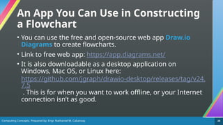
Why Use a Flowchart?
• A flowchart helps you outline a computer program or
process or algorithm clearly [4], [6].
• You want users or even you yourself to be able to
understand how this process works.](https://image.slidesharecdn.com/0203algorithmsandprogrammingcomputercomponents-250120154408-23358de7/85/02_03_Algorithms-and-Programming_Computer-Components-pptx-21-320.jpg)
![Computing Concepts. Prepared by: Engr. Nathaniel M. Cabansay 23
1. Terminator
• Represented by an oval/oblong/pill shape
• Marks the start and the end of the process [6].
• It usually contains the words “Start” or “End” but may also
contain the initial conditions and the outcome of the
process.
Start End](https://image.slidesharecdn.com/0203algorithmsandprogrammingcomputercomponents-250120154408-23358de7/85/02_03_Algorithms-and-Programming_Computer-Components-pptx-23-320.jpg)
![Computing Concepts. Prepared by: Engr. Nathaniel M. Cabansay 24
2. Process
• Represented by a rectangle
• Marks an action or step in the process [6].
• Manual actions and automatic steps use this symbol.
Multiply
integer a by
integer b
Press any key
to continue](https://image.slidesharecdn.com/0203algorithmsandprogrammingcomputercomponents-250120154408-23358de7/85/02_03_Algorithms-and-Programming_Computer-Components-pptx-24-320.jpg)
![Computing Concepts. Prepared by: Engr. Nathaniel M. Cabansay 25
3. Input/Output
• Represented by a parallelogram
• Marks where a system input or a system output takes place
[6].
Input
integer
x
Print
“Hello
world”](https://image.slidesharecdn.com/0203algorithmsandprogrammingcomputercomponents-250120154408-23358de7/85/02_03_Algorithms-and-Programming_Computer-Components-pptx-25-320.jpg)
![Computing Concepts. Prepared by: Engr. Nathaniel M. Cabansay 26
4. Directional Flow
• Represented by an arrow
• Represent the paths a flowchart’s user takes between steps.
Dotted or dashed arrows can represent alternate paths [6].](https://image.slidesharecdn.com/0203algorithmsandprogrammingcomputercomponents-250120154408-23358de7/85/02_03_Algorithms-and-Programming_Computer-Components-pptx-26-320.jpg)
![Computing Concepts. Prepared by: Engr. Nathaniel M. Cabansay 27
5. Decision
• Represented by a diamond
• Represent decisions to be made, often based on a true/false
or yes/no question [6].
Is x
greater
than or
equal to 7?
Does the
input
match the
keyword?](https://image.slidesharecdn.com/0203algorithmsandprogrammingcomputercomponents-250120154408-23358de7/85/02_03_Algorithms-and-Programming_Computer-Components-pptx-27-320.jpg)
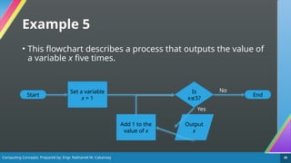
![Computing Concepts. Prepared by: Engr. Nathaniel M. Cabansay 31
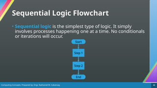
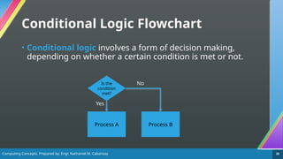
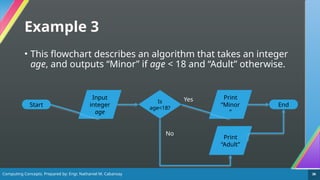
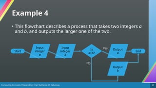
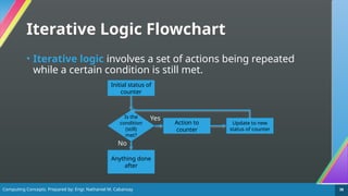
Flowcharts in Programming
• Computer programs can implement three basic types of
logic [7]. These can be described using flowcharts. They are:
1. Sequential Logic – simply executing instructions one after
another
2. Selection/Conditional Logic – deciding the next instructions to
follow based on certain conditions
3. Iterative Logic – repeating execution of a set of instructions
• We will deal with these types of logic in more detail in the
next lessons.](https://image.slidesharecdn.com/0203algorithmsandprogrammingcomputercomponents-250120154408-23358de7/85/02_03_Algorithms-and-Programming_Computer-Components-pptx-31-320.jpg)
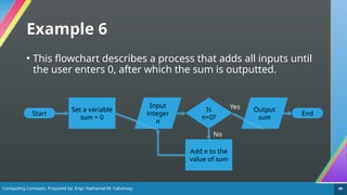
![Computing Concepts. Prepared by: Engr. Nathaniel M. Cabansay 42
Programming
• Computer programs are collections of text that commands
computers to perform algorithms.
• When you write a computer program, you’re in charge! You
are harnessing the computational power of your computer
and making it do what you want it to do.
• Programming languages allow users to write programs to
the computer [8].
• The apps you use everyday were made by programmers,
which you will soon be.](https://image.slidesharecdn.com/0203algorithmsandprogrammingcomputercomponents-250120154408-23358de7/85/02_03_Algorithms-and-Programming_Computer-Components-pptx-42-320.jpg)
![Computing Concepts. Prepared by: Engr. Nathaniel M. Cabansay 43
Programming Languages
• Programming languages come in three types according to
readability [8].
• Machine language – consists of only 0s and 1s. Can be
understood by hardware but not by humans.
• Assembly language/Low-level language – machine-centric
language executed quickly. Humans will have some difficulty
understanding this sort of language. Examples: x86 assembly, x64
assembly.
• High-level language – highly-readable languages easily
understood by humans. Must be converted to low-level languages
by either interpreters or compilers. Examples: C, C++, Python, Java,
C#, FORTRAN, COBOL](https://image.slidesharecdn.com/0203algorithmsandprogrammingcomputercomponents-250120154408-23358de7/85/02_03_Algorithms-and-Programming_Computer-Components-pptx-43-320.jpg)
![Computing Concepts. Prepared by: Engr. Nathaniel M. Cabansay 44
Programming Languages
• Some high-level programming languages include:
• C – a procedural language developed by Dennis Ritchie and is
widely used for system development [1], [8]
• C++ - a superset of C developed by Bjarne Stroustrup. Suitable for
system development while also being suitable for object-oriented
programming. It is used in systems programming (including
embedded systems such as Arduino [9]), and application
programming [1], [8].
• Java – another object-oriented programming language developed
by James Gosling which can run on different hardware as long as a
Java Virtual Machine (JVM) is installed [1], [8]. Widely used in
Android [8].](https://image.slidesharecdn.com/0203algorithmsandprogrammingcomputercomponents-250120154408-23358de7/85/02_03_Algorithms-and-Programming_Computer-Components-pptx-44-320.jpg)
![Computing Concepts. Prepared by: Engr. Nathaniel M. Cabansay 45
Programming Languages
• Some high-level programming languages include:
• Python – an interpreted and object-oriented scripting language
developed by Guido van Rossum which is widely used in artificial
intelligence, machine learning, and data analytics [8].
• JavaScript (JS) – an object-oriented scripting language used to
write programs that run in a web browser [1], [8].
• FORTRAN – language primarily suited for developing programs
related to science and technology. This was one of the first widely-
used high level languages [1].
• COBOL – language primarily suited for developing programs
related to administrative processes [1].](https://image.slidesharecdn.com/0203algorithmsandprogrammingcomputercomponents-250120154408-23358de7/85/02_03_Algorithms-and-Programming_Computer-Components-pptx-45-320.jpg)
![Computing Concepts. Prepared by: Engr. Nathaniel M. Cabansay 46
Programming Languages
• Some high-level programming languages include:
• BASIC – a language frequently used by novices due to its
comparatively easy-to-understand utilization of symbols [1].
• C# – an object-oriented language developed by Microsoft for
the .NET Framework with similar syntax to Java. It is used in
applications and game development.](https://image.slidesharecdn.com/0203algorithmsandprogrammingcomputercomponents-250120154408-23358de7/85/02_03_Algorithms-and-Programming_Computer-Components-pptx-46-320.jpg)
![Computing Concepts. Prepared by: Engr. Nathaniel M. Cabansay 47
Programming Languages
• Some high-level programming languages include:
• Visual BASIC (VB) – another object-oriented language developed
by Microsoft which allows the creation of a program in a visual
environment that uses windows and toolboxes [1]. It is also being
used in the .NET Framework.
• Visual BASIC for Applications (VBA) – a language that allows the
creation of macros, which create a series of specific operations in
an application [1]. Commonly used in Microsoft Excel.](https://image.slidesharecdn.com/0203algorithmsandprogrammingcomputercomponents-250120154408-23358de7/85/02_03_Algorithms-and-Programming_Computer-Components-pptx-47-320.jpg)
![Computing Concepts. Prepared by: Engr. Nathaniel M. Cabansay 48
Programming Languages
• High-level programming languages have two ways of being
translated into machine code [8].
• Interpreted language – translated and executed one instruction
at a time [1]. Examples: Python.
• Compiled language – translated all at once before execution
occurs [8], [1]. Examples: C, C++, C#, Java](https://image.slidesharecdn.com/0203algorithmsandprogrammingcomputercomponents-250120154408-23358de7/85/02_03_Algorithms-and-Programming_Computer-Components-pptx-48-320.jpg)
![Computing Concepts. Prepared by: Engr. Nathaniel M. Cabansay 49
Language Processing
• Language processors convert high-level languages into
machine code [1].
• Compiler – translates entire source programs all at once into
machine language with an executable format.
• Compiled code runs faster than interpreted code.
• Interpreter – executes programs while translating one command
at a time from the source program.
• Bugs are easier to find in interpreted code.](https://image.slidesharecdn.com/0203algorithmsandprogrammingcomputercomponents-250120154408-23358de7/85/02_03_Algorithms-and-Programming_Computer-Components-pptx-49-320.jpg)
![Computing Concepts. Prepared by: Engr. Nathaniel M. Cabansay 50
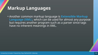
Markup Languages
• Markup languages are used for printing and screen
display. Text is enclosed in marks called tags, with possible
attribute information attached [1].
• The most common markup language is HyperText Markup
Language (HTML), which is commonly used to create web
pages.
• Furthermore, Cascading Style Sheets (CSS) can be used to define
the aesthetics of a webpage.](https://image.slidesharecdn.com/0203algorithmsandprogrammingcomputercomponents-250120154408-23358de7/85/02_03_Algorithms-and-Programming_Computer-Components-pptx-50-320.jpg)
![Computing Concepts. Prepared by: Engr. Nathaniel M. Cabansay 53
Main Units in a Computer
• The hardware functions in your computer can be divided into
five main units [1].
1. Input unit – reads data to be processed by your computer
2. Storage unit – records the data. Separated into main memory and
auxiliary storage.
3. Arithmetic and logical unit (ALU) – performs operations on data in
the storage unit or makes decisions based on the instructions of the
control unit
4. Control unit – interprets a command and gives instructions to the
other units.
5. Output unit – writes the results of the processing in a form that we
can understand.](https://image.slidesharecdn.com/0203algorithmsandprogrammingcomputercomponents-250120154408-23358de7/85/02_03_Algorithms-and-Programming_Computer-Components-pptx-53-320.jpg)
![Computing Concepts. Prepared by: Engr. Nathaniel M. Cabansay 54
Main Units in a Computer
• Below is a diagram showing all five major units [1].
Control
unit
Arithmetic
and Logical
Unit (ALU)
Main storage
unit
Input unit
Output
unit
Orange dashed arrows – data flow
Yellow solid arrows – control flow
CPU](https://image.slidesharecdn.com/0203algorithmsandprogrammingcomputercomponents-250120154408-23358de7/85/02_03_Algorithms-and-Programming_Computer-Components-pptx-54-320.jpg)
![Computing Concepts. Prepared by: Engr. Nathaniel M. Cabansay 55
Integrated Circuits
• An integrated circuit (IC) or chip packages thousands or
even millions of electrical and electronic components like
resistors, capacitors, inductors, diodes and transistors to
create a circuit that can perform a function [10].
• They commonly look like this from above:
NE555 74HC04 ATmega328P
The NE555 is a timer
integrated circuit
The 74HC04 is a logic circuit
(implements negation/NOT)
The ATmega328P is the microcontroller
used by an Arduino Uno](https://image.slidesharecdn.com/0203algorithmsandprogrammingcomputercomponents-250120154408-23358de7/85/02_03_Algorithms-and-Programming_Computer-Components-pptx-55-320.jpg)
![Computing Concepts. Prepared by: Engr. Nathaniel M. Cabansay 56
Classification of Integrated Circuits
[11]
Level of Integration Number of Transistors per Chip
Small Scale Integration (SSI) – logic circuits
(74xx series)
Fewer than 100
Medium Scale Integration (MSI) – basic
operations
100 to 10,000
Large Scale Integration (LSI) – early
microprocessors
10,000 to 100,000
Very Large Scale Integration (VLSI) -
microprocessors handling more than 8 bits
100,000 to 1,000,000
Ultra Large Scale Integration (ULSI) – most
modern microprocessors
More than 1,000,000](https://image.slidesharecdn.com/0203algorithmsandprogrammingcomputercomponents-250120154408-23358de7/85/02_03_Algorithms-and-Programming_Computer-Components-pptx-56-320.jpg)
![Computing Concepts. Prepared by: Engr. Nathaniel M. Cabansay 57
The Processing Unit
• The control unit and the ALU are collectively referred to as
the Central Processing Unit (CPU) or the processor.
• Aside from the ALU and the control unit, the CPU also has
these parts [1]:
• Registers – temporary storage of data inside the CPU.
• Clock generator (or simply clock) – generates clock signals to
synchronize and control timing of operations between various
devices. It also determines the maximum speed at which other
units can operate.
• Bus – signal path for connecting various devices and registers](https://image.slidesharecdn.com/0203algorithmsandprogrammingcomputercomponents-250120154408-23358de7/85/02_03_Algorithms-and-Programming_Computer-Components-pptx-57-320.jpg)
![Computing Concepts. Prepared by: Engr. Nathaniel M. Cabansay 58
Registers
• Computers mainly have these types of registers [1]:
• Instruction register – stores instructions to be executed. Composed of
an instruction and an address part.
• Program counter – stores the address of the instruction to be executed
next.
• General purpose register – can be used for various purposes.
• Accumulator – stores data for computations. Is typically designated as a
general-purpose register.
• Base address register – stores beginning address of a program.
• Index register – stores index for address modification
• Flags – store information of certain statuses.
• Program Status Word – stores running status of a program.](https://image.slidesharecdn.com/0203algorithmsandprogrammingcomputercomponents-250120154408-23358de7/85/02_03_Algorithms-and-Programming_Computer-Components-pptx-58-320.jpg)
![Computing Concepts. Prepared by: Engr. Nathaniel M. Cabansay 59
Buses
• CPUs have three types of buses according to usage [1]:
• Address bus – for specifying the reference address to the main
memory unit
• Control bus – for giving directions to each device from the control
unit.
• Data bus – for exchange of data.](https://image.slidesharecdn.com/0203algorithmsandprogrammingcomputercomponents-250120154408-23358de7/85/02_03_Algorithms-and-Programming_Computer-Components-pptx-59-320.jpg)
![Computing Concepts. Prepared by: Engr. Nathaniel M. Cabansay 60
Buses
• CPUs send out signal through buses in two ways [1]:
• Serial bus – sends data in the sequence of 1 bit each
• Parallel bus – sends multiple bits at once, depending on the bus
width.
• CPUs can also have buses connected in three ways [1]:
• Internal bus – used inside the CPU
• External bus – connects CPU and external devices.
• System bus – collective term for buses directly connected from CPU to outside
• Memory bus – mainly connected to main memory
• Input/output (I/O) bus – mainly connected to input and output devices.
• Expansion bus – connects the CPU and expansion cards.](https://image.slidesharecdn.com/0203algorithmsandprogrammingcomputercomponents-250120154408-23358de7/85/02_03_Algorithms-and-Programming_Computer-Components-pptx-60-320.jpg)
![Computing Concepts. Prepared by: Engr. Nathaniel M. Cabansay 62
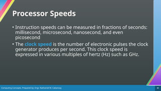
Processor Speeds
• We can also indicate processor speeds by the number of
instructions or operations per second [1]. Two common
metrics are Million Instructions Per Second (MIPS) and
Floating-Point Operations Per Second (FLOPS).
• We can also indicate the execution time of an instruction
using Cycles Per Instruction (CPI), which is the number of
clock pulses required to execute an instruction [1].](https://image.slidesharecdn.com/0203algorithmsandprogrammingcomputercomponents-250120154408-23358de7/85/02_03_Algorithms-and-Programming_Computer-Components-pptx-62-320.jpg)
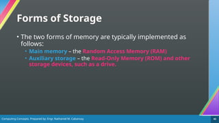
![Computing Concepts. Prepared by: Engr. Nathaniel M. Cabansay 64
Storage
• The computer uses two types of storage [1]:
• Main memory – can directly exchange data with the CPU but is
volatile (contents are lost if power is lost)
• Auxiliary storage – stores data that cannot be accommodated in
main memory and is non-volatile (contents remain even if power is
lost)](https://image.slidesharecdn.com/0203algorithmsandprogrammingcomputercomponents-250120154408-23358de7/85/02_03_Algorithms-and-Programming_Computer-Components-pptx-64-320.jpg)
![Computing Concepts. Prepared by: Engr. Nathaniel M. Cabansay 66
Random Access Memory
• In the Random Access Memory (RAM), all read and write
functions are performed here [1].
• It is the primary memory used by your computer and is
quite fast, and tends to be decently large, typically up to 64
GB (with 8 GB being common for both desktop PCs and
mobile phones).
• It can be classified as Static RAM (SRAM) or Dynamic RAM
(DRAM).](https://image.slidesharecdn.com/0203algorithmsandprogrammingcomputercomponents-250120154408-23358de7/85/02_03_Algorithms-and-Programming_Computer-Components-pptx-66-320.jpg)
![Computing Concepts. Prepared by: Engr. Nathaniel M. Cabansay 67
Main Memory
• The main memory is broadly composed of three
components.
• Memory unit – contains memory cells that record data [1].
• Read/write feature – reads and writes data in the memory cells [1]
. Connects to the CPU Data Bus
• Address selection feature – interprets a specified address and
selects the appropriate memory cell [1]. Connects to the CPU
Address Bus.](https://image.slidesharecdn.com/0203algorithmsandprogrammingcomputercomponents-250120154408-23358de7/85/02_03_Algorithms-and-Programming_Computer-Components-pptx-67-320.jpg)
![Computing Concepts. Prepared by: Engr. Nathaniel M. Cabansay 69
Read Only Memory
• ROM can be classified as [1]:
• Mask ROM – already manufactured with programs and data
• Programmable ROM – can have data written into it only once
• Erasable PROM (EPROM) – can be erased with ultraviolet (UV) light
and rewritten
• Electrically Erasable PROM / EEPROM – can be erased with
electrical signals and rewritten. Includes flash memory.](https://image.slidesharecdn.com/0203algorithmsandprogrammingcomputercomponents-250120154408-23358de7/85/02_03_Algorithms-and-Programming_Computer-Components-pptx-69-320.jpg)
![Computing Concepts. Prepared by: Engr. Nathaniel M. Cabansay 70
Auxiliary Storage Devices
• Auxiliary storage devices include:
• Magnetic disks – use disks with a magnetic material on its surface
and stores data by magnetic variation. Data is stored in concentric
circles referred to as tracks, which are divided into constant lengths
called sectors [1].
• Hard disk drive (HDD) – uses stacked magnetic disks called cylinders in a
firmly sealed case. These tend to be sensitive to vibrations [1]
• Floppy disk (you are most likely to know this as the Save icon) – can be
carried by covering one magnetic disk. Has a small storage capacity and is
easily affected by magnetism [1].](https://image.slidesharecdn.com/0203algorithmsandprogrammingcomputercomponents-250120154408-23358de7/85/02_03_Algorithms-and-Programming_Computer-Components-pptx-70-320.jpg)
![Computing Concepts. Prepared by: Engr. Nathaniel M. Cabansay 71
Auxiliary Storage Devices
• Auxiliary storage devices include:
• Optical discs – removable media where reading and writing of
data are done via laser beams [1].
• Compact disc (CD) – can store about 700 MB of data. Uses a low-energy
infrared laser [12].
• Digital video/versatile disc (DVD) – can store about 4.7 GB of data for a
single-layer DVD, or 8.5 GB for a double-layer DVD. Uses a slightly-higher-
energy red laser [12].
• Blu-ray – can store about 25 GB of data. Uses a high-energy blue laser [12].](https://image.slidesharecdn.com/0203algorithmsandprogrammingcomputercomponents-250120154408-23358de7/85/02_03_Algorithms-and-Programming_Computer-Components-pptx-71-320.jpg)
![Computing Concepts. Prepared by: Engr. Nathaniel M. Cabansay 72
Auxiliary Storage Devices
• Auxiliary storage devices include:
• Solid-state drives (SSD) – flash-memory based auxiliary storage
devices which can access data faster than HDDs [1].
• USB memory / Flash drive – small to medium-sized drives
equipping flash memory with a USB connector [1].
• SD cards / Memory card – small to medium-sized drives where
flash memory is put on a chip and inserted into a dedicated card
slot [1]. Typically used for external storage on mobile phones and
digital single-lens reflex (DSLR) cameras.](https://image.slidesharecdn.com/0203algorithmsandprogrammingcomputercomponents-250120154408-23358de7/85/02_03_Algorithms-and-Programming_Computer-Components-pptx-72-320.jpg)
![Computing Concepts. Prepared by: Engr. Nathaniel M. Cabansay 73
I/O
• Input devices are used for entering data into a computer
[1]. These include the mouse, keyboard, scanners, camera,
microphone, sensors and readers (e.g., barcode readers,
RFID card readers), switches, drawing tablets, and touch
screens.
• Output devices are used for showing the processing results
in a form we can understand [1]. These include the monitor,
printer, speaker, driver units (e.g., motor drivers used to
drive robots) and projector.](https://image.slidesharecdn.com/0203algorithmsandprogrammingcomputercomponents-250120154408-23358de7/85/02_03_Algorithms-and-Programming_Computer-Components-pptx-73-320.jpg)
![Computing Concepts. Prepared by: Engr. Nathaniel M. Cabansay 74
Other Devices
• Communication control units are used for various controls
when the computer is connected to a network [1]. The major
example of this is the Network Interface Card (NIC), which
allows the computer to connect to a network, especially the
Internet.](https://image.slidesharecdn.com/0203algorithmsandprogrammingcomputercomponents-250120154408-23358de7/85/02_03_Algorithms-and-Programming_Computer-Components-pptx-74-320.jpg)
![Computing Concepts. Prepared by: Engr. Nathaniel M. Cabansay 75
Interfacing Devices
• Device drivers are used to control peripheral devices connected
to input/output devices [1].
• Input/output interfaces (or I/O interfaces) are standards or
rules for connecting peripheral devices to computers [1].
• Serial interface – transfers data serially in units of bits [1]
• Parallel interface – transfers data in parallel in units of bytes or words [1].
• Analog I/O interfaces or converters – since computers use digital
signals, analog signals must be converted to digital signals and vice versa
[1].
• Analog-to-digital converter (ADC)
• Digital-to-analog converter (DAC) typically for audio output](https://image.slidesharecdn.com/0203algorithmsandprogrammingcomputercomponents-250120154408-23358de7/85/02_03_Algorithms-and-Programming_Computer-Components-pptx-75-320.jpg)
![Computing Concepts. Prepared by: Engr. Nathaniel M. Cabansay 76
Common Interfaces
• Universal Serial Bus (USB) is a serial interface which can
connect various peripheral devices [1]. Currently, three
generations have been created: USB 1.1, USB 2.0, and USB
3.0.
• Bluetooth – a wireless technology standard connecting
devices such as cell phones and PCs, which uses the 2.4 GHz
frequency band [1].
• High-Definition Multimedia Interface (HDMI) – transmits
audio and video as digital signals [1].](https://image.slidesharecdn.com/0203algorithmsandprogrammingcomputercomponents-250120154408-23358de7/85/02_03_Algorithms-and-Programming_Computer-Components-pptx-76-320.jpg)
![Computing Concepts. Prepared by: Engr. Nathaniel M. Cabansay 78
USB Connector Types
• Universal Serial Bus (USB) has several common connector
types [13]:
• USB-A – the most common types of connector. USB 3.0 ports using
this type of connector are typically indicated in blue.
• USB-B – are square-shaped but larger and are more durable. These
are typically used in printers and scanners.](https://image.slidesharecdn.com/0203algorithmsandprogrammingcomputercomponents-250120154408-23358de7/85/02_03_Algorithms-and-Programming_Computer-Components-pptx-78-320.jpg)
![Computing Concepts. Prepared by: Engr. Nathaniel M. Cabansay 79
USB Connector Types
• Universal Serial Bus (USB) has several common connector
types [13]:
• USB-Mini – the first standard attempt to reduce the size of the USB
connector for smaller devices. These are commonly found on
webcams/cameras.
• USB Micro-B – another attempt to reduce the size of USB
connectors for smaller devices. Commonly found on small devices
like smartphones as charging and data ports.
• USB-C – a reversible USB connector used in devices of all sizes like
laptops and many modern smartphones. These can be used both
for charging and for data transfer.](https://image.slidesharecdn.com/0203algorithmsandprogrammingcomputercomponents-250120154408-23358de7/85/02_03_Algorithms-and-Programming_Computer-Components-pptx-79-320.jpg)
![Computing Concepts. Prepared by: Engr. Nathaniel M. Cabansay 80
Common Device Drivers
• Basic Input/Output System (BIOS) provides the standard
means of input and output in computers [1].
• Plug and Play (PnP) allows the immediate use of a
peripheral device by just connecting it to a computer [1].
• Plug and pray is sometimes used jokingly to refer to either an
unreliable PnP connection or when someone is being skeptical
about a PnP device (Plug the thing in and pray that it works).](https://image.slidesharecdn.com/0203algorithmsandprogrammingcomputercomponents-250120154408-23358de7/85/02_03_Algorithms-and-Programming_Computer-Components-pptx-80-320.jpg)

![Computing Concepts. Prepared by: Engr. Nathaniel M. Cabansay 82
References
[1] Information-Technology Promotion Agency, New FE Textbook Vol. 1: IT Fundamentals,
Tokyo, Japan: Infotech Serve, 2015. Available:
https://lightboat.lightworks.co.jp/en-promotion (accessed Nov. 25, 2024).
[2] S.J. Balo. ICT Proficiency Diagnostic Exam Reviewer, 1st
ed., Philippines. Available:
https://drive.google.com/file/d/16K6r1Niqza3ewN9DFPEZBFBwb2-nIqM3/view
(accessed Nov. 25, 2024)
[3] “Tree Traversal Techniques”. GeeksForGeeks.
https://www.geeksforgeeks.org/tree-traversals-inorder-preorder-and-postorder/
(accessed Nov. 25, 2024)
[4] E. Woo. “Eddie Woo on Play School (2 of 4: Algorithms)”, YouTube, Jan. 1, 2022.
[Online]. Available: https://www.youtube.com/watch?v=UeatzxjFT6A (accessed Nov. 26,
2024)](https://image.slidesharecdn.com/0203algorithmsandprogrammingcomputercomponents-250120154408-23358de7/85/02_03_Algorithms-and-Programming_Computer-Components-pptx-82-320.jpg)
![Computing Concepts. Prepared by: Engr. Nathaniel M. Cabansay 83
References
[5] “What is a flowchart.” Lucidchart. https://www.lucidchart.com/
pages/what-is-a-flowchart-tutorial (accessed Nov. 26, 2024).
[6] “26 popular flowchart symbols explained.” Figma.
https://venngage.com/blog/flowchart-symbols/ (accessed Nov. 26, 2024).
[7] F. J. Mitropulos. “Sequence, selection, and iteration – the building blocks of
programming languages.” LearnProgramming Academy.
https://learnprogramming.academy/programming/
sequence-selection-and-iteration-the-building-blocks-of-programming-languages/
(accessed Nov. 26, 2024)
[8] Test Of Practical Competency in IT. TOPCIT Essence Ver. 3 Technical Field 01 Software
Development, Daejeon, South Korea: Ministry of Science, ICT and Future Planning, 2020.
Available: https://www.topcit.or.kr/upload/edubox/essence/ess_en_01/index.html
(accessed Nov. 26, 2024)](https://image.slidesharecdn.com/0203algorithmsandprogrammingcomputercomponents-250120154408-23358de7/85/02_03_Algorithms-and-Programming_Computer-Components-pptx-83-320.jpg)
![Computing Concepts. Prepared by: Engr. Nathaniel M. Cabansay 84
References
[9] K. Söderby. “Getting Started with Arduino”. Arduino Docs.
https://docs.arduino.cc/learn/starting-guide/getting-started-arduino/ (accessed Nov. 26,
2024).
[10] J. Blom. “Integrated Circuits.” SparkFun. https://learn.sparkfun.com/tutorials/
integrated-circuits/all (accessed Nov. 26, 2024)
[11] “Types of Integrated Circuits”. Geeks for Geeks. https://www.geeksforgeeks.org/
types-of-integrated-circuits/ (accessed Nov. 26, 2024)
[12] OpenStax. “Lasers”. https://phys.libretexts.org/Bookshelves/University_Physics/
University_Physics_(OpenStax)/University_Physics_III_-_Optics_and_Modern_Physics_
(OpenStax)/08%3A_Atomic_Structure/8.07%3A_Lasers (accessed Nov. 27, 2024)
[13] SFUptownMaker, BitSmashed. “Connector Basics.” SparkFun.
https://learn.sparkfun.com/tutorials/connector-basics/usb-connectors (accessed Nov. 27,
2024)](https://image.slidesharecdn.com/0203algorithmsandprogrammingcomputercomponents-250120154408-23358de7/85/02_03_Algorithms-and-Programming_Computer-Components-pptx-84-320.jpg)


![Getting Started with Apache Spark: Big Data Made Simple [Free Meetup]](https://cdn.slidesharecdn.com/ss_thumbnails/apachesparkgettingstarted-260203175547-8361bcc3-thumbnail.jpg?width=640&height=640&fit=bounds)


