This document is a project report on a naphtha cracker plant prepared by Shreenath M. Modi for his bachelor's degree in chemical engineering. It covers the importance of practical training in chemical industries, the production and applications of ethylene, and the various methods of naphtha cracking, including steam cracking and catalytic cracking. The report also includes technical details on the plant's operations, safety measures, and the equipment used.


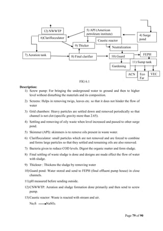


![Natural Gas to Olefins, Symposium[2]](https://cdn.slidesharecdn.com/ss_thumbnails/0b411131-d6a1-4822-ad58-dbcc1933154c-150612193624-lva1-app6891-thumbnail.jpg?width=640&height=640&fit=bounds)


