SlideShare a Scribd company logo
1 of 83
Genera layout of automobile
Components of automobile
1. Frame
2. Engine
3. Clutch
4. Gear Box
5. Universal Joint
6. Propeller Shaft
7. Differential
8.Suspension system
9.Steering mechanism
10.Wheels
11.Braking system
12.Fuel tank
13.Silencer
14.Radiator,Battery and Electrical systems.
15. Vehicle body
16. Axles
Operation of Automobile
• When the driver turns on the starter switch, it releases the
electric current from a battery and sets into action an electrical
starting motor which turns a flywheel connected to the engine
crankshaft.
• Immediately when the driver steps on a pedal which controls the
rate of flow of air fuel mixture into the inlet manifold of the
engine.
• During the four strokes or two strokes power is produced in the
engine cylinder.
• The power is transmitted from the piston to crankshaft by means
of connecting rod.
• As the process of stokes repeated over and over again, the
crankshaft is turned continuously – an the engine is running.
• The motion of the crankshaft is transmitted to the rear wheels
through the clutch, gear box and differential.
• Crankshaft is connected to gear box through clutch mechanism
• By means of gear shift lever, the gears of the transmission can be
shifted to suit driving conditions for changing the speed.
• The motion from the gearbox to the differential is transmitted
through a propeller shaft.
• The differential is arranged in the rear axle to permit one rear wheel
to turn faster than the other while turning a corner.
• The rear wheels are directly connected to the rear axle and get
motion as the rear axle turns – and the vehicle is in motion.
• The motor vehicle, is directed by a steering gear which controls the
direction in which the front wheels are pointed.
• The braking system is provided to stop the vehicle to slow it down as
required by the driver.
• The unevenness of road surfaces and the jerks are partially
controlled by front and rear springs, by shock absorbers, by padding
and springs in the car seats, by chassis cross members which
decrease sideways and by distribution of chassis and body weight as
between front and rear wheels.
AUTO MOBILE
An auto mobile is a self propelled vehicle. It is used for the
transportation of the passengers and goods from one place
to another place on the ground.
REQUIREMENT
1.It should be develop power by itself
2. The rate of power development must be easily
controlled.
3.There should be an arrangement to transmit the power
to the wheels.
4. An arrangement must exist to continue and discontinue
power flow to the wheels.
5. It should be possible to control or vary the torque.
6.It must have direction control.
7. An arrangement must exist to stop the vehicle while it
is running.
AUTO MOBILE
Types
1. With respect to the purpose
2. With respect to capacity
3. With respect to fuel used
4. with respect to number of wheels
5. With respect to drive of the vehicle
6. with respect to side of the drive
7. With respect to transmission
8. With respect to types of suspension
system
Vehicle Layouts
1. There mainly 4 types of vehicle layouts
are in use today.
2. FF(Front-engine, Front-wheel drive)
3. FR(Front-engine, Rear-wheel drive)
4. RR(Rear-engine, Rear-wheel drive)
5. Four Wheel Drive
1. Front engine front wheel drive
Here the engine is in front of the front axle, driving
the front wheels. This layout is typically chosen for its
compact packaging.
Front engine front wheel drive
• Advantages
2. Front-engine Rear-wheel drive
An FR, or Front-engine, Rear-wheel drive layout is
one where the engine is located at the front of the vehicle
and driven wheels are located at the rear.
Front engine rear wheel drive
• Advantages
• The weight of the vehicle is well balanced on all wheels.
• It provides enough space for the luggage
• It provides enough space for steering the front wheels.
• Increased efficiency of the cooling system
• It is easier to repair, inspection and adjust the engine clutch
and gearbox.
• Disadvantages
• Under heavy acceleration, over steering and fish-tailing can
occur.
• Increased weight due to the addition of long propeller shaft.
3. Rear-engine, Rear-wheel drive
A RR, or Rear-engine, Rear-wheel drive layout is
one which places both the engine and drive wheels at the
rear of the vehicle.
Rear engine –rear wheel drive
4. Four-wheel drive
Four-wheel drive, 4WD, 4x4 ("four by four"), or
AWD ("all wheel drive") is a four-wheeled vehicle with a
drive train that allows all four wheels to receive torque
from the engine simultaneously.
Four wheel drive or all wheel drive
Advantages
• Traction is nearly doubled compared to a two
wheel-drive so given sufficient power.
• It suitable for irregularities road surface and
produce high torque compare other drive.
Disadvantages
• High cost compare other drive
• Less fuel efficient compare other drive
An Automobile is constructed with main three parts.
(i) Chassis
(ii) Frame
(iii) Body
Chassis & Frame
Body
Vehicle Construction
Introduction of Chassis
• Chassis is a French term and was initially used to
denote the frame parts or Basic Structure of the
vehicle. It is the back bone of the vehicle. A vehicle
with out body is called Chassis.
• The components of the vehicle like Power plant,
Transmission System, Axles, Wheels and Tyres,
Suspension, Controlling Systems like Braking,
Steering etc., and also electrical system parts are
mounted on the Chassis frame.
• It is the main mounting for all the components
including the body. So it is also called as Carrying
Unit.
CHASSIS
• The various component parts and support systems of a
chassis are
– The power unit – Engine – consists of cylinder,
piston, connecting rod, crankshaft, flywheel,
inlet manifold, outlet manifold, cooling system
(Radiator), lubricating system, Fuel Tank,
Hydraulic Pipes,
– The power train – consists of clutch, gear box,
propeller shaft, universal joints, differentials
gears, rear half axles.
– The running systems – consists of brakes,
wheels, tires, frame, suspension (Rear Springs,
shock absorbers) and the steering system
– The electrical system – consists of different
circuits such as starting circuit, charging
circuit, ignition circuit, lighting circuit and the
horn circuit, Storage battery and cables.
Chassis – Cont.
• The chassis is sub-divided into the running gear and the
power plant.
– Running Gear includes the frame, steering system,
suspension system, brakes, wheels and tyres
– Power Plant include the engine assembly and power
transmission assembly.
• The electrical system is the part of both chassis and body.
Layout of Chassis and its main
Components:
Components of The Chassis
1. Frame
2. Engine
3. Clutch
4. Gear Box
5. Universal Joint
6. Propeller Shaft
7. Differential
8.Suspension system
9.Steering mechanism
10.Wheels
11.Braking system
12.Fuel tank
13.Silencer
14.Radiator,Battery and Electrical systems.
FUNCTIONS OF THE CHASSIS
1. To carry load of the passengers or goods carried in
the body.
2. To support the load of the body, engine, gear box
etc.,
3. To withstand the forces caused due to the sudden
braking or acceleration
4. To withstand the stresses caused due to the bad
road condition.
5. To withstand centrifugal force while cornering
Vehicle Construction
• Classification of Chassis
1. According to Fitting of Engine:
• Full forward Chassis
• Semi forward Chassis
• Bus Chassis
• Engine at back Chassis (Eg. Volvo Bus, Tata nano)
• Engine at Centre Chassis (Eg. Royal tiger master bus)
2. According to No of wheels fitted into vehicle:
* 4 x 2 Drive Chassis [has 4 wheels with 2 driving wheels]
* 4 x 4 Drive Chassis [ has 4 wheels with 4 driving wheels]
* 6 x 2 Drive Chassis [ has 6 wheels with 2 driving wheels]
* 6 x 4 Drive Chassis [ has 6 wheels with 4 driving wheels]
Full forward – Engine outside Drivers Cabin
Semi forward – Half portion outside & half portion
inside driver cabin
Bus Chassis – Engine fitted in driver cabin
Classification of Chassis
a. Full forward – Engine is fitted outside the driver cabin
or seat like in cars and old Tata trucks
b. Semi forward – Half portion of the engine is in the
driver cabin and the remaining half is outside it like in
standard, Bedford pickup vans.
c. Bus chassis – (Forward control) – The engine is fitted in
the driver cabin as in commercial bus.
d. Engine in front – The engine is fitted in front of the
chassis
e. Engine in rear – The engine fitted at the back portion
of the chassis, which does not require long propeller shaft
like Volkswagen of West Germany
f. Engine at Centre – engine fitted at the Centre of the
chassis, which provides full space of chassis floor for use
like in Royal tiger World Master buses of Delhi Transport.
Requirement of Chassis
1.High strength
2.High safety
3. Best durability
4. Best dependability
5.Easy of control
6.High stability
7.High braking ability
8.Simplicity of lubrication
Frame
A rigid Structure of Chassis and skeleton of the vehicle which holds all the parts of
the vehicle.
• It is a rigid structure that forms a skeleton to hold all the major part
together like engine, body, gear box, propeller shaft, rear axles,
wheels, front and rear suspensions, steering gear assemblies,
radiator, braking systems, fuel tank, etc.
• The engine is mounted in the forward end of the frame and at the rear
end of frame, the rear axle housing is attached through the rear
spring.
• The wheels and tire assemblies support the frame.
• Some parts of steering system bolted to the frame and the fuel tank is
fastened to the frame.
• Chassis frame made of cold rolled open earth steel or heat
treated alloy steel
• Side Members may be either of channel or box shaped cross section
(usually have high twisting resistance)
• Cross members are made of Pressed steel, may be either I channel or
tubular cross section.
• Joints are made up of welding or by riveting.
Frame – Cont…
• In a car frame, the frame is narrow at the front to all for a short
turning radius of the front wheels, widening out at the rear to
provide a bigger space in the body.
• The side members are curved upwards at the rear forming the
kickup, which comes over the axles to lower the centre of gravity of
the car.
• The rear left springs connect each end of this curve.
• Truck frames are made of uniform width from end to end.
• The longitudinal members of truck frame are made of channel
sections, which have maximum section at the middle and it
decreases toward the ends.
• The Bumpers provided with the frame is to take the shock of impact
or collision and transfer the same to the frame, which avoiding the
damage to engine, radiator, lamps etc.
Frame – Cont…
• Functions:
– To support the weight of body and passengers
– To accommodate the suspension spring system
– To withstand torques due to engine, transmission, sudden
acceleration and braking action
– To withstand torque stresses due to road shocks
– To withstand sudden impact loads during collisions
– To act as a base for mounting body, engine, transmission,
fuel tank units etc.
– To safely withstand the vibrations set up due to engine and
road bumps.
– To withstand the centrifugal force while cornering
– To withstand the bending stresses and twisting due to the
rise and fall of the front and rear axles.
Types of frames section
Types of Frame:
1. Conventional Frame Construction
2. Semi Integral Frame Construction
3. Integral or Frameless Construction
CONVENTIONAL: SEMI-INTEGRAL: INTEGRAL:
Also called as Non Load carrying frame
As Load carried by Suspension. Frame
Only supports engine & other mountings.
Vehicle Construction
Body mountings are replaced
by stiff material and transfers
part of frame load to the body
also.
Also called as Chassis-less,
Unitary or Monocoque
construction. Pillars are
integrated part of the
frame with stands all
thrusts.
Conventional Frame
Advantages
• Easier body repairs.
• Body can be lighter and cheaper to manufacture
• Any type of body can be made in the case of commercial vehicles.
• It is easy and cheap for hand build.
Disadvantage:
Since it is a 2 dimensional structure, torsional rigidity is very much
lower than other chassis, especially when dealing with vertical load
or bumps.
Truck Frames:
• The bus or truck frames have the channel section
longitudinal members parallel to each other.
• These have maximum section at the middle,
reducing progressively towards the ends.
• Cross members of box section are riveted to the
side members and support the radiator, engine and
the central bearing of the propeller shaft.
• The rear cross frames (two numbers) have mounts
for attaching the leaf spring.
• Members may be hot or cold riveted.
• Low carbon steel (0.15% - 0.20% C, Ni, Si, Mn, P
and S) is used for the manufacture of various
members.
Car frame
Car Frame Design:
 Two longitudinal members, cross members and an X
member.
 Members are made by rolling or pressing methods
 Pressing method will give light weight and rigid frame.
 To obtain uniform strength for minimum weight, the side
members are tapered in depth at both the ends.
 Frame nearer at the front to allow for swinging motion of the
front road wheels due to steering.
 An arched shape at the front and rear allows the up and
down movement of the road wheels.
 This also lowers the centre of gravity of the car, which giving
comfort to the passenger and stability to the car.
 X member (Box or channel section) riveted to the
longitudinal members imparts torsional rigidity to the frame.
 Rear engine cars have the backbone frame forked at the rear
to house the engine and gear box.
Advantages of Frameless cars:
• Lighter construction but stronger
• Cheaper when mass produced
• Lesser body rattles and squeaks
• Improved torsional rigidity
• Provides lower centre of gravity imparting comfort and good road
holding characteristics.
Disadvantages of Frameless Cars:
• Lesser Impact resistance
• Repairs are expensive
• Greater Mechanical noises
• Uneconomical if produced in small numbers
Sub Frames:
• Box Sections
• Carries the engine, clutch, gear box, steering, front suspension and brakes.
• Attached to the body with the help of nuts and bolts.
• The twisting and flexing of the body has no effect on the units supported on the
sub frame.
• Advantages:
– Easy maintenance and repairs, owing to easy accessibility of parts attached
to it.
– The weight of the sub frame helps to damp vibrations
– Reduces production time.
Loads on Chassis Frame:
1. Load of Short duration:
Occurs when Vehicle crosses broken patch of road results in LONGITUDINAL TORSION.
2. Combined Loads of moment:
Occurs when negotiating curve, apply brakes, striking a pothole results in BENDING & TORSION.
3. Inertia Loads:
Occurs when applied brake for short period results in BENDING OF SIDE MEMBERS
4. Static Loads:
Due to weight of engine, steering, gearbox etc.
5. Over Loads:
Load on the vehicle beyond the specified design. (Eg.MTC Bus in Peak Hours)
6. Other Loads:
Load due to side wind, cornering force while taking a turn – results in
LATERAL BENDING OF SIDE MEMBERS & Load due to Wheel impact with road obstacles –
results in DISTORTION OF FRAME.
MATERIALS FOR FRAME:
1. Mild Steel sheet,
2. Carbon steel Sheet,
3. Nickel alloy steel sheet
Composition of Nickel Alloy Steel Sheet:
Carbon:0.25-0.35%, Manganese:0.35-0.75%,Silicon-0.30%(Max)
Nickel-3%,Phosporous-0.05%(max) & Sulphur – 0.5%(max)
Vehicle Construction
Requirement of a Good Frame:
• Must be Strong and Light
• To withstand Shocks, twists, and vibration
• Must resist distorting forces like weight of the components & passengers causing
sagging effect due to bending.
• Must resist horizontal force due to road irregularities & Upward twisting force caused by
road shocks.
Vehicle Construction
BODY:
• Body is to provide accommodation to the driver and the passengers and to
protect them against varying weather conditions.
• Body is the super structure of the vehicle.
• Body is bolted to the chassis which is a cover to the chassis.
• Different types of bodies are attached to the chassis to make a complete
vehicle.
• Body may be conventional or integral (unitized) design.
• Various parts of the body are:
– Floor assembly
– Panels
– Cowl or bonnet assembly
– Roof assembly
– Rear trunk lid
– Quarter Panels
– Front side assembly
– Engine Hood
– Bumpers
– Doors
Body Cont….
Requirements of Body:
Body Should be Light
 have minimum number of components
 have long fatigue life.
 have uniformly distributed load.
 provide sufficient space for passengers and luggage.
 have good access to the engine and suspension system.
 create minimum vibrations when the vehicle is running.
 have minimum resistance to air.
 be cheap and easy in manufacturing
 provide clear all-round vision through glass areas.
 be attractive in shape and colour.
Body Cont….
TYPES OF AUTOMOBILE BODIES
1.Passenger body
2. Commercial body
1. According to chassis design
Conventional Construction
Semi Integral Construction
Integral or Frameless Construction
2. According to usage
(a) Light vehicle- cars, jeeps
(b) Heavy vehicle- buses, lorries
(c) medium vehicle- vans
3.According to shell forming the exterior of a car
a. Hatch back b. Sports car c. four door sedan d. limousine
b. e. convertible f. Van g. Hard top h. Pick up truck
Body Cont….
Vehicle Construction
VEHICLE BODY:
Types of Vehicle Body:
1. CAR 2.Truck 3. Tractor 4. Trailer
5. Tanker 6. Dumper Truck 7. Van 8. Jeep
9. Mini Bus 10. Bus 11. Three Wheeler
Vehicle Construction
VEHICLE BODY:
Construction & Components:
Various Components of Vehicle Body is grouped into 3 categories
1.Structure: All Load Carrying Elements are Structures
2.Finish: Unstressed Units like Bonnet, lid, bumper etc. are Finish
3. Equipment: Parts like Seats, Doors, Windows etc. are Equipment
Vehicle Construction
VEHICLE BODY:
Construction & Components:
Two Panels in Body Construction -> Outer Panel (Provides Shape of the body)
-> Inner Panel (Reinforces Shell of the body)
Two panels are welded together and to the pillars and rails to form the Skeleton of
the Car body.
1.Floor Assembly:
• Made up of pressed steel panels divides front, centre and rear sections usually.
• Metal Strips are welded at floor to provide strength, rigidity.
• Wheel house panel welded to the floor to provide sufficient clearance for wheels.
Vehicle Construction
VEHICLE BODY:
Construction & Components:
2. Cowl Assembly
• Cowl is the front portion of the car and made up of many smaller panel stamping of
sheet metal.
• Windshield frame accommodates wind shield.
• Dash board accommodates different warning & indicating devices.
• Side of the cowl are used for hinges for front doors.
Vehicle Construction
VEHICLE BODY:
Construction & Components:
3. Pillar and Roof assembly:
• Classified as A Pillar, B Pillar and C Pillar in modern cars and Centre (B) Pillar
supports rear doors and hinges.
• Rail roof and centre pillar made up of box section to provide max strength.
• Drip mountings are added to the side of rail roof.
• Rear window, Front Windshields are attached to the roof panel by spot welding.
Vehicle Construction
VEHICLE BODY:
Construction & Components:
4. Quarter Panel: This panel is welded to rear wheel house panel, floor panel and the
rear side of the roof.
5. Front / Rear Door Assembly: LH & RH doors are assembled together to
corresponding pillars
Vehicle Construction
VEHICLE BODY:
Construction & Components:
5. Seats & Other Interiors: Its design depends on number of passengers, comfortness
and aesthetics & ergonomics.
Material Used for Body Construction:
Floor Panel/Roof Panel/Cowl and other Sheet metals:
Aluminium sheets for light weight and resistance to corrosion (or)
Stainless Steel Sheets which give more stiffness and strength than aluminium.
Side mountings/Accessories:
Thermosetting plastics and rubbers
Windshield and Other glass doors (Backlite & Side door):
Toughened & Laminated Glass
Automotive vehicle aerodynamics
 Automotive aerodynamics is the study of the
aerodynamics of the road vehicles. Its main goals are
reducing drag and wind noise, minimizing noise
emission, and preventing undesired lift forces and
other causes of aerodynamic instability at high speeds.
 Automotive aerodynamics is studied using both
computer modelling and wind tunnel testing.
Objectives of improvement of flow
past vehicle bodies.
 1. Reduction of fuel consumption.
 2. More favorable comfort characteristics( mud deposition
on body, noise, ventilating and cooling of passenger
comportment)
 3. Improvement of driving characteristics (Stability
,handling, traffic safety)
 Vehicle aerodynamics includes three interacting flow fields
 1.Flow past vehicle body
 2.Flow past vehicle components (wheels,heatexchanger,
brakes, windshield)
 3.Floe past in passenger compartment
Dynamic characteristics of vehicles
 1.Aero dynamic resistance
 A. turbulent air flow around vehicle body (75%)
 B.Friction of air over vehicle body(12%)
 C.Vehicle component resistance, from radiators and air
vents(3%)
 Forces causes to resistance
 Drag force,
 Lifting force
 Cross wind force
Aero Dynamics is the Behavior of air in motion relative to vehicle body.
1.Drag Force (Fx): Force of air acting in the direction of vehicle motion in longitudinal direction.
It is also called air resistance. This
offers resistance to vehicle motion &
calculated by:
Fx = CxρV2(A/2) where
Cx – Drag Coefficient
ρ – Density of Air
V- Velocity of Air &
A – Projected Area of vehicle viewed from front.
The profile of the body should be designed in such a way to reduce the drag force
2. Lift Force (Fz): It is the vertical force caused by
Pressure distribution on the body.
Fz = CzρV2(A/2)
Cz is the drag coefficient.
Latest Design Vehicles to reduce drag & lift
Resistance to Vehicle Motion (or) Aero Dynamics
3.Crosswind Force (Fy):
It is the force acting in the lateral direction
on the side of the vehicle .
 2. Rolling resistance
 These forces are mainly due to frictional effect on
moving parts of the vehicle, and also include the
frictional slip between road surface and tire.
 A.Resistance from tire deformation(90%)
 B. Tire surface compression(4%)
 C.Tire slippage and air circulation around wheel.(6%)
 3.Grade resistance
 When vehicle move up a grade, a component of the
weight of the vehicle acts downward, along the plane
of the highway. This creates a force acting in a
direction opposite that of the motion.
 4. Curve resistance
 When a vehicle turn a curve, external forces act on the
front wheels of the vehicle. These forces have component
that retarding effect on the forward motion of the vehicle.
The sum of these components provides the curve
resistance.
 5. Traction
 Traction is defined as the adhesive friction of the tire to the
road surface.
 1. Driving traction
 2.Braking traction
 3.Cornering traction
Aerodynamics
 An automobile is a small object submerged amid vast
surrounding of air.
 The motion of the vehicle takes place through a large mass of
either stationary air, or air in motion.
 The air exerts force on the auto vehicle.
 The body of the vehicle which is mainly exposed to the air.
 An arbitrary shaped body will experience a large air resistance
which implies that there is more loss of engines power.
 Consequently less power will be available to propel the
automobile thereby causing less load carrying capacity and
slow speed for the same fuel consumption.
 Thus there exists a need to profile aerodynamically suitable
body.
Aerodynamics:
 The force exerted by air on a moving auto vehicle had two components.
 One in the direction of motion and the other in a direction perpendicular to
the motion.
 The force in the direction of motion is called drag FD and that in the
perpendicular direction is known as Lift FL.
 For the good body profile the lift force should be zero or negligible and the
total force on the body is drag force.
 The viscosity of air is mainly responsible for drag on the body.
 The arbitrary shaped body of an automobile held stationary in a stream of air
moving at an uniform velocity V experiences shear force along its tangential
direction and pressure force in the normal direction.
 The shear forces are called friction drag force FDf and the pressure forces are
know as pressure drag force FDp..
 The total drag on the body is therefore the sum of friction and pressure drags.
 The magnitudes of friction drag and pressure drag depend on shape of the
body.
 The drag and lift may be calculated from
FD = CD A ρV2/2
FL = CL A ρV2/2
 Where CD is coefficient of drag and CL is coefficient of Lift. A is
characteristic area of the body which is the largest projected area
of body on a plane perpendicular to the direction of flow of the
air.
 The separation of flow, and the difference of pressure on the
upstream and downstream sides of the moving vehicles are
responsible for the Wake. (Lifting of small or light objects on the
downstream of a fast moving vehicle).
 Wake should be avoided or minimized by proper profiling of the
body.
 The contouring of body should be such that the separation of
flow does not occur, and the pressure difference is not much on
the upstream and downstream sides.
 To achieve it, the modern cars employ a rear spoiler that adds to
aerodynamic styling of the body.
 The formed wakes can be different sizes according to shape of the body.
 The magnitude of pressure drag depends on the size of the wake.
 The size of the wake will be large in a body such as circular disc having
sharp edges than well rounded bodies.
 The wake and therefore the drag force is extremely small in case of
streamlined body.
 In a well streamlined object, the friction drag is larger than the pressure
drag.
 The coefficient of drag depends on shape of the body in high velocity air
streams.
 As compared to flat headed body in which CD = 0.85 at 300 kmph, this
value is only 0.15 in sharp pointed projection of racing cars. Hence the
racing cars are made of the profile as shown.
 The pressure (drag) and suction (Lift) distribution on a typical car body
is shown in figure.
 Rolling Resistance: Mainly due to the friction between wheel tyres and
road surface. 1 to 2% of total weight of vehicle. It depends upon the
following factors
 Load on each road wheel,
 Type of tyre tread
 Wheel inflation pressure
 Nature of road surface.
 Wind or air resistance: This type of resistance due to the following factors
 The shape and size of the vehicle body
 Air velocity
 Speed of the vehicle.
 It increases as the square of the vehicle speed owing to which much
importance is given to streamlining and frontal area of modern
automobiles.
 Gradient resistance: This is due to steepness of road gradient. It is
subject to vehicle weight and road gradient which does not depend upon
vehicle speed.

More Related Content

Similar to unit1 new.pptx

Automobile Engineering.ppt
Automobile Engineering.pptAutomobile Engineering.ppt
Automobile Engineering.pptsivasankar480633
 
Basic of automobile.ppt
Basic of automobile.pptBasic of automobile.ppt
Basic of automobile.pptGurinder Singh
 
automobile workshop ppt Traning report by c rang rajan and sudhir kumar
automobile workshop ppt Traning report by c rang rajan and sudhir kumarautomobile workshop ppt Traning report by c rang rajan and sudhir kumar
automobile workshop ppt Traning report by c rang rajan and sudhir kumarchakrawarti rang rajan
 
automobile engineering
automobile engineeringautomobile engineering
automobile engineeringSaurabh Negi
 
Defining Automotive Technology by SouLSteer
Defining Automotive Technology by SouLSteerDefining Automotive Technology by SouLSteer
Defining Automotive Technology by SouLSteerShobhit Gosain
 
1.power plant and locations
1.power plant and locations1.power plant and locations
1.power plant and locationsshaikusmanshag
 
Gear box- transmission system of automobiles
Gear box- transmission system of automobilesGear box- transmission system of automobiles
Gear box- transmission system of automobilesKodanda Ramarao
 
Four wheel steering system for Automobile
Four wheel steering system for Automobile Four wheel steering system for Automobile
Four wheel steering system for Automobile ijiert bestjournal
 
Four Wheel Steering System.
Four Wheel Steering System.Four Wheel Steering System.
Four Wheel Steering System.mudassir khan
 
Vehicle Structure and Engines
Vehicle Structure and EnginesVehicle Structure and Engines
Vehicle Structure and EnginesPraveenManickam2
 
M.tech 1st sem automobile that useful for development
M.tech 1st sem automobile that useful for developmentM.tech 1st sem automobile that useful for development
M.tech 1st sem automobile that useful for developmentBinayaBhusanPanda
 
1.vbe intro compatibility-mode_
1.vbe intro compatibility-mode_1.vbe intro compatibility-mode_
1.vbe intro compatibility-mode_navinrawat27
 
Introduction to automotive system
Introduction to automotive system Introduction to automotive system
Introduction to automotive system CrazyBeats1
 
ppt_ae.pdf business research progress report
ppt_ae.pdf business research progress reportppt_ae.pdf business research progress report
ppt_ae.pdf business research progress reportpdhruvil518
 

Similar to unit1 new.pptx (20)

Automobile Engineering.ppt
Automobile Engineering.pptAutomobile Engineering.ppt
Automobile Engineering.ppt
 
Unit 1 Introduction to automobile and drive train
Unit 1 Introduction to automobile and drive trainUnit 1 Introduction to automobile and drive train
Unit 1 Introduction to automobile and drive train
 
Basic of automobile.ppt
Basic of automobile.pptBasic of automobile.ppt
Basic of automobile.ppt
 
Automobile Engineering.ppsx
Automobile Engineering.ppsxAutomobile Engineering.ppsx
Automobile Engineering.ppsx
 
automobile workshop ppt Traning report by c rang rajan and sudhir kumar
automobile workshop ppt Traning report by c rang rajan and sudhir kumarautomobile workshop ppt Traning report by c rang rajan and sudhir kumar
automobile workshop ppt Traning report by c rang rajan and sudhir kumar
 
automobile engineering
automobile engineeringautomobile engineering
automobile engineering
 
Defining Automotive Technology by SouLSteer
Defining Automotive Technology by SouLSteerDefining Automotive Technology by SouLSteer
Defining Automotive Technology by SouLSteer
 
1.power plant and locations
1.power plant and locations1.power plant and locations
1.power plant and locations
 
Gear box- transmission system of automobiles
Gear box- transmission system of automobilesGear box- transmission system of automobiles
Gear box- transmission system of automobiles
 
Four wheel steering system for Automobile
Four wheel steering system for Automobile Four wheel steering system for Automobile
Four wheel steering system for Automobile
 
unit - 1.ppt
unit - 1.pptunit - 1.ppt
unit - 1.ppt
 
Unit 1-61
Unit 1-61Unit 1-61
Unit 1-61
 
Four Wheel Steering System.
Four Wheel Steering System.Four Wheel Steering System.
Four Wheel Steering System.
 
engine
engineengine
engine
 
Vehicle Structure and Engines
Vehicle Structure and EnginesVehicle Structure and Engines
Vehicle Structure and Engines
 
M.tech 1st sem automobile that useful for development
M.tech 1st sem automobile that useful for developmentM.tech 1st sem automobile that useful for development
M.tech 1st sem automobile that useful for development
 
Unit- I.pptx
Unit- I.pptxUnit- I.pptx
Unit- I.pptx
 
1.vbe intro compatibility-mode_
1.vbe intro compatibility-mode_1.vbe intro compatibility-mode_
1.vbe intro compatibility-mode_
 
Introduction to automotive system
Introduction to automotive system Introduction to automotive system
Introduction to automotive system
 
ppt_ae.pdf business research progress report
ppt_ae.pdf business research progress reportppt_ae.pdf business research progress report
ppt_ae.pdf business research progress report
 

Recently uploaded

Work Experience-Dalton Park.pptxfvvvvvvv
Work Experience-Dalton Park.pptxfvvvvvvvWork Experience-Dalton Park.pptxfvvvvvvv
Work Experience-Dalton Park.pptxfvvvvvvvLewisJB
 
Gurgaon ✡️9711147426✨Call In girls Gurgaon Sector 51 escort service
Gurgaon ✡️9711147426✨Call In girls Gurgaon Sector 51 escort serviceGurgaon ✡️9711147426✨Call In girls Gurgaon Sector 51 escort service
Gurgaon ✡️9711147426✨Call In girls Gurgaon Sector 51 escort servicejennyeacort
 
main PPT.pptx of girls hostel security using rfid
main PPT.pptx of girls hostel security using rfidmain PPT.pptx of girls hostel security using rfid
main PPT.pptx of girls hostel security using rfidNikhilNagaraju
 
Call Girls Narol 7397865700 Independent Call Girls
Call Girls Narol 7397865700 Independent Call GirlsCall Girls Narol 7397865700 Independent Call Girls
Call Girls Narol 7397865700 Independent Call Girlsssuser7cb4ff
 
Introduction to Machine Learning Unit-3 for II MECH
Introduction to Machine Learning Unit-3 for II MECHIntroduction to Machine Learning Unit-3 for II MECH
Introduction to Machine Learning Unit-3 for II MECHC Sai Kiran
 
Call Girls Delhi {Jodhpur} 9711199012 high profile service
Call Girls Delhi {Jodhpur} 9711199012 high profile serviceCall Girls Delhi {Jodhpur} 9711199012 high profile service
Call Girls Delhi {Jodhpur} 9711199012 high profile servicerehmti665
 
IVE Industry Focused Event - Defence Sector 2024
IVE Industry Focused Event - Defence Sector 2024IVE Industry Focused Event - Defence Sector 2024
IVE Industry Focused Event - Defence Sector 2024Mark Billinghurst
 
Artificial-Intelligence-in-Electronics (K).pptx
Artificial-Intelligence-in-Electronics (K).pptxArtificial-Intelligence-in-Electronics (K).pptx
Artificial-Intelligence-in-Electronics (K).pptxbritheesh05
 
Past, Present and Future of Generative AI
Past, Present and Future of Generative AIPast, Present and Future of Generative AI
Past, Present and Future of Generative AIabhishek36461
 
Decoding Kotlin - Your guide to solving the mysterious in Kotlin.pptx
Decoding Kotlin - Your guide to solving the mysterious in Kotlin.pptxDecoding Kotlin - Your guide to solving the mysterious in Kotlin.pptx
Decoding Kotlin - Your guide to solving the mysterious in Kotlin.pptxJoão Esperancinha
 
What are the advantages and disadvantages of membrane structures.pptx
What are the advantages and disadvantages of membrane structures.pptxWhat are the advantages and disadvantages of membrane structures.pptx
What are the advantages and disadvantages of membrane structures.pptxwendy cai
 
Heart Disease Prediction using machine learning.pptx
Heart Disease Prediction using machine learning.pptxHeart Disease Prediction using machine learning.pptx
Heart Disease Prediction using machine learning.pptxPoojaBan
 
EduAI - E learning Platform integrated with AI
EduAI - E learning Platform integrated with AIEduAI - E learning Platform integrated with AI
EduAI - E learning Platform integrated with AIkoyaldeepu123
 
complete construction, environmental and economics information of biomass com...
complete construction, environmental and economics information of biomass com...complete construction, environmental and economics information of biomass com...
complete construction, environmental and economics information of biomass com...asadnawaz62
 
Electronically Controlled suspensions system .pdf
Electronically Controlled suspensions system .pdfElectronically Controlled suspensions system .pdf
Electronically Controlled suspensions system .pdfme23b1001
 
DATA ANALYTICS PPT definition usage example
DATA ANALYTICS PPT definition usage exampleDATA ANALYTICS PPT definition usage example
DATA ANALYTICS PPT definition usage examplePragyanshuParadkar1
 

Recently uploaded (20)

9953056974 Call Girls In South Ex, Escorts (Delhi) NCR.pdf
9953056974 Call Girls In South Ex, Escorts (Delhi) NCR.pdf9953056974 Call Girls In South Ex, Escorts (Delhi) NCR.pdf
9953056974 Call Girls In South Ex, Escorts (Delhi) NCR.pdf
 
Work Experience-Dalton Park.pptxfvvvvvvv
Work Experience-Dalton Park.pptxfvvvvvvvWork Experience-Dalton Park.pptxfvvvvvvv
Work Experience-Dalton Park.pptxfvvvvvvv
 
Gurgaon ✡️9711147426✨Call In girls Gurgaon Sector 51 escort service
Gurgaon ✡️9711147426✨Call In girls Gurgaon Sector 51 escort serviceGurgaon ✡️9711147426✨Call In girls Gurgaon Sector 51 escort service
Gurgaon ✡️9711147426✨Call In girls Gurgaon Sector 51 escort service
 
Design and analysis of solar grass cutter.pdf
Design and analysis of solar grass cutter.pdfDesign and analysis of solar grass cutter.pdf
Design and analysis of solar grass cutter.pdf
 
main PPT.pptx of girls hostel security using rfid
main PPT.pptx of girls hostel security using rfidmain PPT.pptx of girls hostel security using rfid
main PPT.pptx of girls hostel security using rfid
 
Call Girls Narol 7397865700 Independent Call Girls
Call Girls Narol 7397865700 Independent Call GirlsCall Girls Narol 7397865700 Independent Call Girls
Call Girls Narol 7397865700 Independent Call Girls
 
Introduction to Machine Learning Unit-3 for II MECH
Introduction to Machine Learning Unit-3 for II MECHIntroduction to Machine Learning Unit-3 for II MECH
Introduction to Machine Learning Unit-3 for II MECH
 
Call Girls Delhi {Jodhpur} 9711199012 high profile service
Call Girls Delhi {Jodhpur} 9711199012 high profile serviceCall Girls Delhi {Jodhpur} 9711199012 high profile service
Call Girls Delhi {Jodhpur} 9711199012 high profile service
 
IVE Industry Focused Event - Defence Sector 2024
IVE Industry Focused Event - Defence Sector 2024IVE Industry Focused Event - Defence Sector 2024
IVE Industry Focused Event - Defence Sector 2024
 
Artificial-Intelligence-in-Electronics (K).pptx
Artificial-Intelligence-in-Electronics (K).pptxArtificial-Intelligence-in-Electronics (K).pptx
Artificial-Intelligence-in-Electronics (K).pptx
 
Past, Present and Future of Generative AI
Past, Present and Future of Generative AIPast, Present and Future of Generative AI
Past, Present and Future of Generative AI
 
Decoding Kotlin - Your guide to solving the mysterious in Kotlin.pptx
Decoding Kotlin - Your guide to solving the mysterious in Kotlin.pptxDecoding Kotlin - Your guide to solving the mysterious in Kotlin.pptx
Decoding Kotlin - Your guide to solving the mysterious in Kotlin.pptx
 
young call girls in Rajiv Chowk🔝 9953056974 🔝 Delhi escort Service
young call girls in Rajiv Chowk🔝 9953056974 🔝 Delhi escort Serviceyoung call girls in Rajiv Chowk🔝 9953056974 🔝 Delhi escort Service
young call girls in Rajiv Chowk🔝 9953056974 🔝 Delhi escort Service
 
What are the advantages and disadvantages of membrane structures.pptx
What are the advantages and disadvantages of membrane structures.pptxWhat are the advantages and disadvantages of membrane structures.pptx
What are the advantages and disadvantages of membrane structures.pptx
 
POWER SYSTEMS-1 Complete notes examples
POWER SYSTEMS-1 Complete notes  examplesPOWER SYSTEMS-1 Complete notes  examples
POWER SYSTEMS-1 Complete notes examples
 
Heart Disease Prediction using machine learning.pptx
Heart Disease Prediction using machine learning.pptxHeart Disease Prediction using machine learning.pptx
Heart Disease Prediction using machine learning.pptx
 
EduAI - E learning Platform integrated with AI
EduAI - E learning Platform integrated with AIEduAI - E learning Platform integrated with AI
EduAI - E learning Platform integrated with AI
 
complete construction, environmental and economics information of biomass com...
complete construction, environmental and economics information of biomass com...complete construction, environmental and economics information of biomass com...
complete construction, environmental and economics information of biomass com...
 
Electronically Controlled suspensions system .pdf
Electronically Controlled suspensions system .pdfElectronically Controlled suspensions system .pdf
Electronically Controlled suspensions system .pdf
 
DATA ANALYTICS PPT definition usage example
DATA ANALYTICS PPT definition usage exampleDATA ANALYTICS PPT definition usage example
DATA ANALYTICS PPT definition usage example
 

unit1 new.pptx

  • 1.
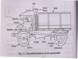
  • 2. Genera layout of automobile
  • 3. Components of automobile 1. Frame 2. Engine 3. Clutch 4. Gear Box 5. Universal Joint 6. Propeller Shaft 7. Differential 8.Suspension system 9.Steering mechanism 10.Wheels 11.Braking system 12.Fuel tank 13.Silencer 14.Radiator,Battery and Electrical systems. 15. Vehicle body 16. Axles
  • 4. Operation of Automobile • When the driver turns on the starter switch, it releases the electric current from a battery and sets into action an electrical starting motor which turns a flywheel connected to the engine crankshaft. • Immediately when the driver steps on a pedal which controls the rate of flow of air fuel mixture into the inlet manifold of the engine. • During the four strokes or two strokes power is produced in the engine cylinder. • The power is transmitted from the piston to crankshaft by means of connecting rod. • As the process of stokes repeated over and over again, the crankshaft is turned continuously – an the engine is running. • The motion of the crankshaft is transmitted to the rear wheels through the clutch, gear box and differential.
  • 5. • Crankshaft is connected to gear box through clutch mechanism • By means of gear shift lever, the gears of the transmission can be shifted to suit driving conditions for changing the speed. • The motion from the gearbox to the differential is transmitted through a propeller shaft. • The differential is arranged in the rear axle to permit one rear wheel to turn faster than the other while turning a corner. • The rear wheels are directly connected to the rear axle and get motion as the rear axle turns – and the vehicle is in motion. • The motor vehicle, is directed by a steering gear which controls the direction in which the front wheels are pointed. • The braking system is provided to stop the vehicle to slow it down as required by the driver. • The unevenness of road surfaces and the jerks are partially controlled by front and rear springs, by shock absorbers, by padding and springs in the car seats, by chassis cross members which decrease sideways and by distribution of chassis and body weight as between front and rear wheels.
  • 6. AUTO MOBILE An auto mobile is a self propelled vehicle. It is used for the transportation of the passengers and goods from one place to another place on the ground. REQUIREMENT 1.It should be develop power by itself 2. The rate of power development must be easily controlled. 3.There should be an arrangement to transmit the power to the wheels. 4. An arrangement must exist to continue and discontinue power flow to the wheels. 5. It should be possible to control or vary the torque. 6.It must have direction control. 7. An arrangement must exist to stop the vehicle while it is running.
  • 7. AUTO MOBILE Types 1. With respect to the purpose 2. With respect to capacity 3. With respect to fuel used 4. with respect to number of wheels 5. With respect to drive of the vehicle 6. with respect to side of the drive 7. With respect to transmission 8. With respect to types of suspension system
  • 8. Vehicle Layouts 1. There mainly 4 types of vehicle layouts are in use today. 2. FF(Front-engine, Front-wheel drive) 3. FR(Front-engine, Rear-wheel drive) 4. RR(Rear-engine, Rear-wheel drive) 5. Four Wheel Drive
  • 9. 1. Front engine front wheel drive Here the engine is in front of the front axle, driving the front wheels. This layout is typically chosen for its compact packaging.
  • 10.
  • 11. Front engine front wheel drive • Advantages
  • 12. 2. Front-engine Rear-wheel drive An FR, or Front-engine, Rear-wheel drive layout is one where the engine is located at the front of the vehicle and driven wheels are located at the rear.
  • 13.
  • 14. Front engine rear wheel drive • Advantages • The weight of the vehicle is well balanced on all wheels. • It provides enough space for the luggage • It provides enough space for steering the front wheels. • Increased efficiency of the cooling system • It is easier to repair, inspection and adjust the engine clutch and gearbox. • Disadvantages • Under heavy acceleration, over steering and fish-tailing can occur. • Increased weight due to the addition of long propeller shaft.
  • 15. 3. Rear-engine, Rear-wheel drive A RR, or Rear-engine, Rear-wheel drive layout is one which places both the engine and drive wheels at the rear of the vehicle.
  • 16.
  • 17. Rear engine –rear wheel drive
  • 18. 4. Four-wheel drive Four-wheel drive, 4WD, 4x4 ("four by four"), or AWD ("all wheel drive") is a four-wheeled vehicle with a drive train that allows all four wheels to receive torque from the engine simultaneously.
  • 19.
  • 20. Four wheel drive or all wheel drive Advantages • Traction is nearly doubled compared to a two wheel-drive so given sufficient power. • It suitable for irregularities road surface and produce high torque compare other drive. Disadvantages • High cost compare other drive • Less fuel efficient compare other drive
  • 21.
  • 22. An Automobile is constructed with main three parts. (i) Chassis (ii) Frame (iii) Body Chassis & Frame Body Vehicle Construction
  • 23. Introduction of Chassis • Chassis is a French term and was initially used to denote the frame parts or Basic Structure of the vehicle. It is the back bone of the vehicle. A vehicle with out body is called Chassis. • The components of the vehicle like Power plant, Transmission System, Axles, Wheels and Tyres, Suspension, Controlling Systems like Braking, Steering etc., and also electrical system parts are mounted on the Chassis frame. • It is the main mounting for all the components including the body. So it is also called as Carrying Unit.
  • 24. CHASSIS • The various component parts and support systems of a chassis are – The power unit – Engine – consists of cylinder, piston, connecting rod, crankshaft, flywheel, inlet manifold, outlet manifold, cooling system (Radiator), lubricating system, Fuel Tank, Hydraulic Pipes, – The power train – consists of clutch, gear box, propeller shaft, universal joints, differentials gears, rear half axles. – The running systems – consists of brakes, wheels, tires, frame, suspension (Rear Springs, shock absorbers) and the steering system – The electrical system – consists of different circuits such as starting circuit, charging circuit, ignition circuit, lighting circuit and the horn circuit, Storage battery and cables.
  • 25. Chassis – Cont. • The chassis is sub-divided into the running gear and the power plant. – Running Gear includes the frame, steering system, suspension system, brakes, wheels and tyres – Power Plant include the engine assembly and power transmission assembly. • The electrical system is the part of both chassis and body.
  • 26. Layout of Chassis and its main Components:
  • 27.
  • 28.
  • 29.
  • 30. Components of The Chassis 1. Frame 2. Engine 3. Clutch 4. Gear Box 5. Universal Joint 6. Propeller Shaft 7. Differential 8.Suspension system 9.Steering mechanism 10.Wheels 11.Braking system 12.Fuel tank 13.Silencer 14.Radiator,Battery and Electrical systems.
  • 31. FUNCTIONS OF THE CHASSIS 1. To carry load of the passengers or goods carried in the body. 2. To support the load of the body, engine, gear box etc., 3. To withstand the forces caused due to the sudden braking or acceleration 4. To withstand the stresses caused due to the bad road condition. 5. To withstand centrifugal force while cornering
  • 32. Vehicle Construction • Classification of Chassis 1. According to Fitting of Engine: • Full forward Chassis • Semi forward Chassis • Bus Chassis • Engine at back Chassis (Eg. Volvo Bus, Tata nano) • Engine at Centre Chassis (Eg. Royal tiger master bus) 2. According to No of wheels fitted into vehicle: * 4 x 2 Drive Chassis [has 4 wheels with 2 driving wheels] * 4 x 4 Drive Chassis [ has 4 wheels with 4 driving wheels] * 6 x 2 Drive Chassis [ has 6 wheels with 2 driving wheels] * 6 x 4 Drive Chassis [ has 6 wheels with 4 driving wheels] Full forward – Engine outside Drivers Cabin Semi forward – Half portion outside & half portion inside driver cabin Bus Chassis – Engine fitted in driver cabin
  • 33. Classification of Chassis a. Full forward – Engine is fitted outside the driver cabin or seat like in cars and old Tata trucks b. Semi forward – Half portion of the engine is in the driver cabin and the remaining half is outside it like in standard, Bedford pickup vans. c. Bus chassis – (Forward control) – The engine is fitted in the driver cabin as in commercial bus. d. Engine in front – The engine is fitted in front of the chassis e. Engine in rear – The engine fitted at the back portion of the chassis, which does not require long propeller shaft like Volkswagen of West Germany f. Engine at Centre – engine fitted at the Centre of the chassis, which provides full space of chassis floor for use like in Royal tiger World Master buses of Delhi Transport.
  • 34. Requirement of Chassis 1.High strength 2.High safety 3. Best durability 4. Best dependability 5.Easy of control 6.High stability 7.High braking ability 8.Simplicity of lubrication
  • 35. Frame A rigid Structure of Chassis and skeleton of the vehicle which holds all the parts of the vehicle. • It is a rigid structure that forms a skeleton to hold all the major part together like engine, body, gear box, propeller shaft, rear axles, wheels, front and rear suspensions, steering gear assemblies, radiator, braking systems, fuel tank, etc. • The engine is mounted in the forward end of the frame and at the rear end of frame, the rear axle housing is attached through the rear spring. • The wheels and tire assemblies support the frame. • Some parts of steering system bolted to the frame and the fuel tank is fastened to the frame. • Chassis frame made of cold rolled open earth steel or heat treated alloy steel • Side Members may be either of channel or box shaped cross section (usually have high twisting resistance) • Cross members are made of Pressed steel, may be either I channel or tubular cross section. • Joints are made up of welding or by riveting.
  • 36. Frame – Cont… • In a car frame, the frame is narrow at the front to all for a short turning radius of the front wheels, widening out at the rear to provide a bigger space in the body. • The side members are curved upwards at the rear forming the kickup, which comes over the axles to lower the centre of gravity of the car. • The rear left springs connect each end of this curve. • Truck frames are made of uniform width from end to end. • The longitudinal members of truck frame are made of channel sections, which have maximum section at the middle and it decreases toward the ends. • The Bumpers provided with the frame is to take the shock of impact or collision and transfer the same to the frame, which avoiding the damage to engine, radiator, lamps etc.
  • 37. Frame – Cont… • Functions: – To support the weight of body and passengers – To accommodate the suspension spring system – To withstand torques due to engine, transmission, sudden acceleration and braking action – To withstand torque stresses due to road shocks – To withstand sudden impact loads during collisions – To act as a base for mounting body, engine, transmission, fuel tank units etc. – To safely withstand the vibrations set up due to engine and road bumps. – To withstand the centrifugal force while cornering – To withstand the bending stresses and twisting due to the rise and fall of the front and rear axles.
  • 38. Types of frames section
  • 39. Types of Frame: 1. Conventional Frame Construction 2. Semi Integral Frame Construction 3. Integral or Frameless Construction CONVENTIONAL: SEMI-INTEGRAL: INTEGRAL: Also called as Non Load carrying frame As Load carried by Suspension. Frame Only supports engine & other mountings. Vehicle Construction Body mountings are replaced by stiff material and transfers part of frame load to the body also. Also called as Chassis-less, Unitary or Monocoque construction. Pillars are integrated part of the frame with stands all thrusts.
  • 40.
  • 41. Conventional Frame Advantages • Easier body repairs. • Body can be lighter and cheaper to manufacture • Any type of body can be made in the case of commercial vehicles. • It is easy and cheap for hand build. Disadvantage: Since it is a 2 dimensional structure, torsional rigidity is very much lower than other chassis, especially when dealing with vertical load or bumps.
  • 42. Truck Frames: • The bus or truck frames have the channel section longitudinal members parallel to each other. • These have maximum section at the middle, reducing progressively towards the ends. • Cross members of box section are riveted to the side members and support the radiator, engine and the central bearing of the propeller shaft. • The rear cross frames (two numbers) have mounts for attaching the leaf spring. • Members may be hot or cold riveted. • Low carbon steel (0.15% - 0.20% C, Ni, Si, Mn, P and S) is used for the manufacture of various members.
  • 43.
  • 45. Car Frame Design:  Two longitudinal members, cross members and an X member.  Members are made by rolling or pressing methods  Pressing method will give light weight and rigid frame.  To obtain uniform strength for minimum weight, the side members are tapered in depth at both the ends.  Frame nearer at the front to allow for swinging motion of the front road wheels due to steering.  An arched shape at the front and rear allows the up and down movement of the road wheels.  This also lowers the centre of gravity of the car, which giving comfort to the passenger and stability to the car.  X member (Box or channel section) riveted to the longitudinal members imparts torsional rigidity to the frame.  Rear engine cars have the backbone frame forked at the rear to house the engine and gear box.
  • 46.
  • 47.
  • 48.
  • 49.
  • 50. Advantages of Frameless cars: • Lighter construction but stronger • Cheaper when mass produced • Lesser body rattles and squeaks • Improved torsional rigidity • Provides lower centre of gravity imparting comfort and good road holding characteristics. Disadvantages of Frameless Cars: • Lesser Impact resistance • Repairs are expensive • Greater Mechanical noises • Uneconomical if produced in small numbers
  • 51. Sub Frames: • Box Sections • Carries the engine, clutch, gear box, steering, front suspension and brakes. • Attached to the body with the help of nuts and bolts. • The twisting and flexing of the body has no effect on the units supported on the sub frame. • Advantages: – Easy maintenance and repairs, owing to easy accessibility of parts attached to it. – The weight of the sub frame helps to damp vibrations – Reduces production time.
  • 52. Loads on Chassis Frame: 1. Load of Short duration: Occurs when Vehicle crosses broken patch of road results in LONGITUDINAL TORSION. 2. Combined Loads of moment: Occurs when negotiating curve, apply brakes, striking a pothole results in BENDING & TORSION. 3. Inertia Loads: Occurs when applied brake for short period results in BENDING OF SIDE MEMBERS 4. Static Loads: Due to weight of engine, steering, gearbox etc. 5. Over Loads: Load on the vehicle beyond the specified design. (Eg.MTC Bus in Peak Hours) 6. Other Loads: Load due to side wind, cornering force while taking a turn – results in LATERAL BENDING OF SIDE MEMBERS & Load due to Wheel impact with road obstacles – results in DISTORTION OF FRAME. MATERIALS FOR FRAME: 1. Mild Steel sheet, 2. Carbon steel Sheet, 3. Nickel alloy steel sheet Composition of Nickel Alloy Steel Sheet: Carbon:0.25-0.35%, Manganese:0.35-0.75%,Silicon-0.30%(Max) Nickel-3%,Phosporous-0.05%(max) & Sulphur – 0.5%(max) Vehicle Construction
  • 53. Requirement of a Good Frame: • Must be Strong and Light • To withstand Shocks, twists, and vibration • Must resist distorting forces like weight of the components & passengers causing sagging effect due to bending. • Must resist horizontal force due to road irregularities & Upward twisting force caused by road shocks. Vehicle Construction
  • 54. BODY: • Body is to provide accommodation to the driver and the passengers and to protect them against varying weather conditions. • Body is the super structure of the vehicle. • Body is bolted to the chassis which is a cover to the chassis. • Different types of bodies are attached to the chassis to make a complete vehicle. • Body may be conventional or integral (unitized) design. • Various parts of the body are: – Floor assembly – Panels – Cowl or bonnet assembly – Roof assembly – Rear trunk lid – Quarter Panels – Front side assembly – Engine Hood – Bumpers – Doors
  • 55. Body Cont…. Requirements of Body: Body Should be Light  have minimum number of components  have long fatigue life.  have uniformly distributed load.  provide sufficient space for passengers and luggage.  have good access to the engine and suspension system.  create minimum vibrations when the vehicle is running.  have minimum resistance to air.  be cheap and easy in manufacturing  provide clear all-round vision through glass areas.  be attractive in shape and colour.
  • 56. Body Cont…. TYPES OF AUTOMOBILE BODIES 1.Passenger body 2. Commercial body 1. According to chassis design Conventional Construction Semi Integral Construction Integral or Frameless Construction 2. According to usage (a) Light vehicle- cars, jeeps (b) Heavy vehicle- buses, lorries (c) medium vehicle- vans 3.According to shell forming the exterior of a car a. Hatch back b. Sports car c. four door sedan d. limousine b. e. convertible f. Van g. Hard top h. Pick up truck
  • 58. Vehicle Construction VEHICLE BODY: Types of Vehicle Body: 1. CAR 2.Truck 3. Tractor 4. Trailer 5. Tanker 6. Dumper Truck 7. Van 8. Jeep 9. Mini Bus 10. Bus 11. Three Wheeler
  • 60. Vehicle Construction VEHICLE BODY: Construction & Components: Various Components of Vehicle Body is grouped into 3 categories 1.Structure: All Load Carrying Elements are Structures 2.Finish: Unstressed Units like Bonnet, lid, bumper etc. are Finish 3. Equipment: Parts like Seats, Doors, Windows etc. are Equipment
  • 61. Vehicle Construction VEHICLE BODY: Construction & Components: Two Panels in Body Construction -> Outer Panel (Provides Shape of the body) -> Inner Panel (Reinforces Shell of the body) Two panels are welded together and to the pillars and rails to form the Skeleton of the Car body. 1.Floor Assembly: • Made up of pressed steel panels divides front, centre and rear sections usually. • Metal Strips are welded at floor to provide strength, rigidity. • Wheel house panel welded to the floor to provide sufficient clearance for wheels.
  • 62. Vehicle Construction VEHICLE BODY: Construction & Components: 2. Cowl Assembly • Cowl is the front portion of the car and made up of many smaller panel stamping of sheet metal. • Windshield frame accommodates wind shield. • Dash board accommodates different warning & indicating devices. • Side of the cowl are used for hinges for front doors.
  • 63. Vehicle Construction VEHICLE BODY: Construction & Components: 3. Pillar and Roof assembly: • Classified as A Pillar, B Pillar and C Pillar in modern cars and Centre (B) Pillar supports rear doors and hinges. • Rail roof and centre pillar made up of box section to provide max strength. • Drip mountings are added to the side of rail roof. • Rear window, Front Windshields are attached to the roof panel by spot welding.
  • 64. Vehicle Construction VEHICLE BODY: Construction & Components: 4. Quarter Panel: This panel is welded to rear wheel house panel, floor panel and the rear side of the roof. 5. Front / Rear Door Assembly: LH & RH doors are assembled together to corresponding pillars
  • 65. Vehicle Construction VEHICLE BODY: Construction & Components: 5. Seats & Other Interiors: Its design depends on number of passengers, comfortness and aesthetics & ergonomics. Material Used for Body Construction: Floor Panel/Roof Panel/Cowl and other Sheet metals: Aluminium sheets for light weight and resistance to corrosion (or) Stainless Steel Sheets which give more stiffness and strength than aluminium. Side mountings/Accessories: Thermosetting plastics and rubbers Windshield and Other glass doors (Backlite & Side door): Toughened & Laminated Glass
  • 66. Automotive vehicle aerodynamics  Automotive aerodynamics is the study of the aerodynamics of the road vehicles. Its main goals are reducing drag and wind noise, minimizing noise emission, and preventing undesired lift forces and other causes of aerodynamic instability at high speeds.  Automotive aerodynamics is studied using both computer modelling and wind tunnel testing.
  • 67. Objectives of improvement of flow past vehicle bodies.  1. Reduction of fuel consumption.  2. More favorable comfort characteristics( mud deposition on body, noise, ventilating and cooling of passenger comportment)  3. Improvement of driving characteristics (Stability ,handling, traffic safety)  Vehicle aerodynamics includes three interacting flow fields  1.Flow past vehicle body  2.Flow past vehicle components (wheels,heatexchanger, brakes, windshield)  3.Floe past in passenger compartment
  • 68. Dynamic characteristics of vehicles  1.Aero dynamic resistance  A. turbulent air flow around vehicle body (75%)  B.Friction of air over vehicle body(12%)  C.Vehicle component resistance, from radiators and air vents(3%)  Forces causes to resistance  Drag force,  Lifting force  Cross wind force
  • 69. Aero Dynamics is the Behavior of air in motion relative to vehicle body. 1.Drag Force (Fx): Force of air acting in the direction of vehicle motion in longitudinal direction. It is also called air resistance. This offers resistance to vehicle motion & calculated by: Fx = CxρV2(A/2) where Cx – Drag Coefficient ρ – Density of Air V- Velocity of Air & A – Projected Area of vehicle viewed from front. The profile of the body should be designed in such a way to reduce the drag force 2. Lift Force (Fz): It is the vertical force caused by Pressure distribution on the body. Fz = CzρV2(A/2) Cz is the drag coefficient. Latest Design Vehicles to reduce drag & lift Resistance to Vehicle Motion (or) Aero Dynamics
  • 70.
  • 71. Resistance to Vehicle Motion (or) Aero Dynamics 3.Crosswind Force (Fy): It is the force acting in the lateral direction on the side of the vehicle .
  • 72.
  • 73.  2. Rolling resistance  These forces are mainly due to frictional effect on moving parts of the vehicle, and also include the frictional slip between road surface and tire.  A.Resistance from tire deformation(90%)  B. Tire surface compression(4%)  C.Tire slippage and air circulation around wheel.(6%)  3.Grade resistance  When vehicle move up a grade, a component of the weight of the vehicle acts downward, along the plane of the highway. This creates a force acting in a direction opposite that of the motion.
  • 74.  4. Curve resistance  When a vehicle turn a curve, external forces act on the front wheels of the vehicle. These forces have component that retarding effect on the forward motion of the vehicle. The sum of these components provides the curve resistance.  5. Traction  Traction is defined as the adhesive friction of the tire to the road surface.  1. Driving traction  2.Braking traction  3.Cornering traction
  • 75. Aerodynamics  An automobile is a small object submerged amid vast surrounding of air.  The motion of the vehicle takes place through a large mass of either stationary air, or air in motion.  The air exerts force on the auto vehicle.  The body of the vehicle which is mainly exposed to the air.  An arbitrary shaped body will experience a large air resistance which implies that there is more loss of engines power.  Consequently less power will be available to propel the automobile thereby causing less load carrying capacity and slow speed for the same fuel consumption.  Thus there exists a need to profile aerodynamically suitable body.
  • 76. Aerodynamics:  The force exerted by air on a moving auto vehicle had two components.  One in the direction of motion and the other in a direction perpendicular to the motion.  The force in the direction of motion is called drag FD and that in the perpendicular direction is known as Lift FL.  For the good body profile the lift force should be zero or negligible and the total force on the body is drag force.  The viscosity of air is mainly responsible for drag on the body.  The arbitrary shaped body of an automobile held stationary in a stream of air moving at an uniform velocity V experiences shear force along its tangential direction and pressure force in the normal direction.  The shear forces are called friction drag force FDf and the pressure forces are know as pressure drag force FDp..  The total drag on the body is therefore the sum of friction and pressure drags.  The magnitudes of friction drag and pressure drag depend on shape of the body.
  • 77.
  • 78.  The drag and lift may be calculated from FD = CD A ρV2/2 FL = CL A ρV2/2  Where CD is coefficient of drag and CL is coefficient of Lift. A is characteristic area of the body which is the largest projected area of body on a plane perpendicular to the direction of flow of the air.  The separation of flow, and the difference of pressure on the upstream and downstream sides of the moving vehicles are responsible for the Wake. (Lifting of small or light objects on the downstream of a fast moving vehicle).  Wake should be avoided or minimized by proper profiling of the body.  The contouring of body should be such that the separation of flow does not occur, and the pressure difference is not much on the upstream and downstream sides.
  • 79.  To achieve it, the modern cars employ a rear spoiler that adds to aerodynamic styling of the body.  The formed wakes can be different sizes according to shape of the body.  The magnitude of pressure drag depends on the size of the wake.  The size of the wake will be large in a body such as circular disc having sharp edges than well rounded bodies.  The wake and therefore the drag force is extremely small in case of streamlined body.  In a well streamlined object, the friction drag is larger than the pressure drag.  The coefficient of drag depends on shape of the body in high velocity air streams.  As compared to flat headed body in which CD = 0.85 at 300 kmph, this value is only 0.15 in sharp pointed projection of racing cars. Hence the racing cars are made of the profile as shown.  The pressure (drag) and suction (Lift) distribution on a typical car body is shown in figure.
  • 80.
  • 81.
  • 82.  Rolling Resistance: Mainly due to the friction between wheel tyres and road surface. 1 to 2% of total weight of vehicle. It depends upon the following factors  Load on each road wheel,  Type of tyre tread  Wheel inflation pressure  Nature of road surface.  Wind or air resistance: This type of resistance due to the following factors  The shape and size of the vehicle body  Air velocity  Speed of the vehicle.  It increases as the square of the vehicle speed owing to which much importance is given to streamlining and frontal area of modern automobiles.  Gradient resistance: This is due to steepness of road gradient. It is subject to vehicle weight and road gradient which does not depend upon vehicle speed.
  • 83.  Rolling Resistance: Mainly due to the friction between wheel tyres and road surface. 1 to 2% of total weight of vehicle. It depends upon the following factors  Load on each road wheel,  Type of tyre tread  Wheel inflation pressure  Nature of road surface.  Wind or air resistance: This type of resistance due to the following factors  The shape and size of the vehicle body  Air velocity  Speed of the vehicle.  It increases as the square of the vehicle speed owing to which much importance is given to streamlining and frontal area of modern automobiles.  Gradient resistance: This is due to steepness of road gradient. It is subject to vehicle weight and road gradient which does not depend upon vehicle speed.