2. Formula Hybrid Electrical Tutorial
Fusing, version 1.0 Page 2
Branch Circuits
Consider fusing for this circuit, with one source and
three loads.
One option is to use a fuse 25% larger than the total
current (12 A x 1.25 = 15 A), and use wire rated for 15
A throughout the circuit, as shown, right.
Note that the fuse should be adjacent to the power
source. Any wiring between the power source and the
fuse is unprotected—if a short occurs in that part of
the system, the fuse cannot offer any protection.
The disadvantage of the single-fuse approach is that it
requires big wire everywhere, even for circuits that
only use 1 A. An alternative is to use smaller wire for
the low-current part of the circuit, and to include a fuse
to protect that part of the circuit, as shown, right.
We could even go crazy with that approach and put
fuses in each branch of the circuit, so as to be able to
use wire as small as possible in each branch, as
shown, right.
But that would be a terrible design! Not only does
it have more fuses than loads, but it also has fuses
everywhere in the system. If one of them failed, it
would be a nightmare to find it.
10 A 1 A1 A
15 A
fuse
15 A wire
2.5 A fuse
2.5 A wire
2.5 A wire
10 A 1 A1 A
15 A
fuse
15 A wire
10 A
1 A1 A
15 A
fuse
15 A wire
2.5
A fuse
12.5 A
fuse
12.5 A
wire
1.25 A fuse
1.25 A
fuse
1.25 A wire
1.25 A wire
2.5 A wire
10 A 1 A1 A
3. Formula Hybrid Electrical Tutorial
Fusing, version 1.0 Page 3
A better design is to put all the fuses in one spot.
For 12 V automotive and marine systems,
inexpensive fuse blocks are readily available in
various sizes and configurations; they can make
constructing a safe, convenient, and reliable 12 V
power system very easy.
If locating the fuse block away from the power
source is necessary, a master fuse is needed protect
the wiring between the power source and the fuse
block. Other reasons for including a master fuse
are discussed under fuse ratings.
Fuse Ratings
A fuse’s current rating, the maximum current it can continuously carry without blowing, might seem like the only
parameter you need to know. However, fuses also have voltage ratings, interrupting capacity ratings, and various
ratings related to the speed at which they blow.
If a fuse is used in a circuit with a higher voltage than its rating, or if the short-circuit current in the circuit exceeds
the interrupting capacity of the fuse, it might not be able to safely open the circuit even after the element melts. An
arc can continue the current through the fuse even after the element melts—in this case the fuse does not succeed
in stopping current flow. Or, the fuse may explode, spewing hot metal around and starting a fire rather than
preventing one.
The voltage rating must be at least the maximum voltage in the system. Multiple fuses in series do not help—each
one must be rated for the full voltage. That’s because one will trip first, and the full voltage can appear across that
one fuse1. The voltage rating of a fuse for ac voltage is often higher than the voltage rating of the same fuse for dc
voltage. That’s because the zero crossing of an ac voltage can help extinguish an arc, whereas with dc the arc is
more likely to continue. The dc rating may be less than half the ac rating; some fuses are not rated for interrupting
dc at all. Formula Hybrid rules require that dc systems use fuses rated for dc.
The interrupting rating of the fuse must be greater than the possible short circuit current in the circuit. With grid-
powered systems, calculating the short-circuit current is complex, but with battery and ultracapacitor systems, the
short-circuit current of a cell is the cell voltage divided by the series resistance of the cell. When cells are combined
in series, the short circuit current remains the same; when they are connected in parallel the short circuit currents
increase. For example, for a Maxwell BCAP3000 ultracap, the cell voltage is 2.7 V, and the ESR is 0.37 ohms. That
means the short-circuit current is 7300 A. An A123 ANR26650 Li-ion cell is rated 3.3 V and 10 millohms (for a 1
1
http://www.ferrazshawmut.com/en/pdf/edupack/GB110_Fuses_in_series.pdf
1 A10 A 1 A
1.25 A
1.25 A
12.5 A
2.5 A wire
15 A wire
12.5 A
wire
1.25 A wire
1 A10 A 1 A
1.25 A
1.25 A
12.5 A
2.5 A wire
15 A wire
12.5 A
wire
1.25 A wire
15 A
fuse
4. Formula Hybrid Electrical Tutorial
Fusing, version 1.0 Page 4
second dc pulse). That means a 330-A short-circuit current. The interrupting rating may be lower for dc than for
ac.
In a system with a master fuse and additional branch-circuit fuses, the interrupting capacity of the branch-circuit
fuses need only be equal to the rating of the master fuse. This can help you avoid buying many exotic high-
interrupting capacity fuses for a system with a high-current source.
Fusing Multiple Sources
With multiple power sources, each power source needs to be fused, unless a source has inherently limited current
capability, and the wire size is adequate for that current. In some cases, this may require fuses at both ends of a
particular wire run. For example, in the drawing below, the left battery, which is intended to put out 8 A, has a 10
A fuse and 10 A wire. It needs fuses at both ends of the run of 10 A wire, because the 10 A wire wouldn’t be
protected by the 15 A fuse on the main battery.
If a source is inherently current-limited, and the wire is rated for at least that current, no fuse is required at the
source. However, a fuse might be required at the end of the wire that connects to other parts of the system. For
example, if we replace the battery on the left in the above example with a generator, inherently limited to 8 A, the
left 10 A fuse may be omitted, but the right one is still needed, because current could flow from the main system
back into the generator wires if they were to short out.
Sometimes a battery or ultracapacitor bank has multiple cells or strings of cells connected in parallel. In that case, it
is necessary to fuse each string separately, even if there is no run of wire outside the battery box (see next page).
These fuses protect against overcurrent from one string charging another string, as could happen if a cell shorted.
1 A10 A 1 A
1.25 A
1.25 A
12.5 A
2.5 A wire
15 A wire
12.5 A
wire
1.25 A wire
15 A
fuse
8 A generator
10 A
fuse
10 A wire
1 A10 A 1 A
1.25 A
1.25 A
12.5 A
2.5 A wire
15 A wire
12.5 A
wire
1.25 A wire
15 A
fuse
10 A
fuse
10 A
fuse
10 A wire
5. Formula Hybrid Electrical Tutorial
Fusing, version 1.0 Page 5
Measurement circuits
Often there is a need to connect some small wires to a power circuit in order to make measurements, power a small
auxiliary circuit, or connect balancing circuits to a battery or ultracapacitor bank. Since these are not power
circuits, it’s easy to forget that they might need fusing. A 24 AWG wire connected to a 100 A circuit will likely act
as a fuse itself if it is shorted, which might seem to obviate the need for a fuse, but fuses safely encase their hot
metal inside a glass or ceramic tube, sometimes filled with sand. A plastic-insulated wire that melts could start a
fire and/or cause another insulation failure that might cause a higher-current short, or produce a shock hazard.
The straightforward solution is to do exactly as we did before and add a fuse each place that a smaller wire
connects to a high-current system. One other solution is to place a resistor in the same place the fuse would go,
with the resistor value chosen to limit the short-circuit current to a level that is safe for the wires.
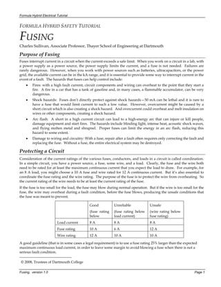
Time Dependence
Fuses take time to blow. The further they are over the current limit, the faster they blow. This characteristic can
work well for protecting wire from overheating, because wire also takes time to heat up. Each fuse time has a
different characteristic, described by a time-current curve. A good time-current curve will show a shaded area.
Below the shaded area, the fuse is guaranteed not to blow; above it, it is guaranteed to interrupt the circuit.
1 A10 A 1 A
1.25 A
1.25 A
12.5 A
2.5 A wire
15 A wire
12.5 A
wire
1.25 A wire
5 A fuse
5 A fuse 5 A
fuse
Current (log scale)
Time
(log scale)
300 A
5 s
15 s
Example fuse curve:
This fuse would be guaranteed to
clear within 15 seconds at 300 A.
Thus, it could safely protect a wire
that would overheat after 16 seconds
of 300 A current. It is guaranteed
not to melt before 5 seconds with a
300 A current. Thus, it could be
used in a system designed to have
currents of 250 A (for example) for 5
6. Formula Hybrid Electrical Tutorial
Fusing, version 1.0 Page 6
Protecting semiconductors with fuses is, however, harder than protecting wire, as semiconductors can heat up and
fail very rapidly in an overcurrent situation. For this purpose, special very fast blowing fuses are available. They
often are not fast enough to protect the semiconductor from failing, but may prevent the failure from being as
violent, allowing repair to be more feasible.
On the other hand, a slow-blowing fuse can be very useful in a system such as a vehicle, where high currents are
often expected to last only a short time (e.g., 10 seconds during acceleration). A very fast fuse would need to be
sized for that full current (although even a fast fuse might take double its rated current for 10 seconds). But a slow
(“time-delay”) fuse might be able to carry as much as five times its rated current for 10 seconds. Using a fuse rated
for a lower current isn’t in and of itself an advantage, but doing so could allow using smaller wire. Using wire
rated for 50 A for a short 100 A pulse is fine as long as it is for a short enough time that the wire won’t overheat.
Here’s an example using this approach:
The 10 A time-delay fuse protects the 10 A wire. The 25 A fast fuse is only needed if the load itself has
semiconductors that need protection that is not already built into the load. For example, some motor controllers do
not have internal fuses and recommend external fast fuses.
Although the use of time-delay fuses can make it safe to use wire rated for lower currents, doing so is not
necessarily the best choice for high performance: the added power loss and voltage drop in thinner wire could
degrade efficiency and acceleration capability of the vehicle. Comparing these effects to the effect of greater weight
and cost in larger wire could lead you to a good choice of wire size.
Other Protection Devices
Circuit breakers—switches that automatically open upon an overcurrent condition—can be an attractive alternative
to fuses. Similar ratings apply, and as for fuses, it is essential to find ones that are rated for dc if they are used in a
dc application, for the same reason as with fuses. The advantages of circuit breakers are that they can be reset
rather than replaced after they trip, and, in many cases, they can provide a useful switching function as well as a
protection function.
PTC (positive temperature coefficient) resistors rapidly increase in resistance if too much current makes them get
hot. This can provide similar protection to a fuse or circuit breaker. In the case of a fault, the circuit won’t be
completely interrupted—a smaller current will continue to flow, maintaining the temperature of the PTC. After the
fault it removed, it will cool and effectively reset itself. PTCs are available only for currents and voltages that are
low compared to the electric drive system in a hybrid vehicle, but they can be useful for the low-voltage (e.g. 12 V)
system in a vehicle. Note that they generally have higher resistance (even when not tripped) than fuses or circuit
breakers.
pulsed load:
35 A for
10 seconds;
10 A for one
minute.
10 A time-
delay fuse
25 A fast
“semiconductor”
fuse
10 A wire