
Recommended
More Related Content
What's hot
What's hot (20)
Similar to Syrm
Similar to Syrm (20)
Recently uploaded
Recently uploaded (20)
Syrm
- 2. Unit – II SYNCHRONUS RELUCTANCE MOTOR Unit Syllabus Constructional features, operating principle and characteristics of synchronous reluctance motor
- 3. Reluctance Motors • An induction motor with a modified squirrel- cage rotor – Single-phase or Three-phase – rotor turns in synchronism with the rotating magnetic flux
- 4. What is synchronous reluctance motor? • Stator consists of multiple salient (ie. projecting) electromagnet poles, similar to a wound field brushed DC motor • Ferromagnetic rotor(non-permanent magnetic poles) • Torque is generated through the phenomenon of magnetic reluctance. • The rotor consists of soft magnetic material, such as laminated silicon steel, which has multiple projections acting as salient magnetic poles through magnetic reluctance. • Number of rotor poles is less than the number of stator poles, which minimizes torque ripple.
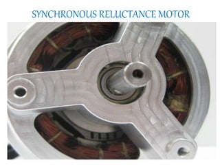
- 6. Construction
- 7. Construction
- 9. Types based on magnetization • Radial Type • Axial type
- 11. Distributed Anisotropy cage motors
- 12. Axially laminated Anisotropic rotor
- 13. Types of Rotor Three different types of SynRM with anisotropic rotor structures a) Simple salient pole (SP) rotor b) Axially laminated rotor c) Transversally laminated rotor
- 14. Simple salient pole (SP) rotor • The salient pole rotor is made by removing some iron material in the transversal region. Four-pole conventional salient pole design
- 15. Axially laminated rotor • In the axially laminated rotor, the laminations (iron) are suitably shaped at each pole and insulated from each other using electrically and magnetically passive materials (insulation) and the resulting stacks are connected through pole holders to the central region to which the shaft is connected. Four-pole axially-laminated rotor design
- 16. Transversally laminated rotor (Mostly Employed) • In the third type of rotor the laminations are punched in the traditional way. Thin ribs are left when punching, thus the various rotor segments are connected to each other by these ribs. Four-pole transversally-laminated rotor design
- 17. AXIAL TYPE RADIAL TYPE Axially laminated rotor Radially laminated rotor By increasing the Ld/Lq ratio, we obtain more PF and efficiency By decreasing Ld/Lq ratio, circulating flux in the rotor pole faces Designed to have high saliency Designed to have optimized flux guide Offers good performance, torque, PF, efficiency To obtain less ripple torque, less iron losses it is designed Rotor has 2 designs Rotor has 1 design Shaft may be rectangular cross section Shaft may be circular cross section High speed applications Poor choice for high speed applications
- 18. Operating Principle When a stator pole is energized, the rotor torque is in the direction that will reduce reluctance. Thus the nearest rotor pole is pulled into alignment with the stator field (a position of less reluctance). In order to sustain rotation, the stator field must rotate in advance of the rotor poles, thus constantly "pulling" the rotor along.
- 19. Operation • Rotor accelerates towards synchronous speed • At a “critical” speed, the low-reluctance paths provided by the salient poles will cause them to “snap” into synchronism with the rotating flux.
- 20. Operation (continued) • When the rotor synchronizes, slip is equal to zero • Rotor pulled around by “reluctance torque” • Figure at right shows the rotor synchronized at no load
- 21. Operation (continued) • A “step” increase in load slows the rotor down, and the rotor poles “lag” the stator poles. • The angle of lag, δ, is called the “torque angle”. • The maximum torque angle, δmax = 45°.
- 22. Operation at maximum load • Maximum load is when δ = 45°. • If load increases so that δ>45°, the flux path is “over stretched” and the rotor falls out of synchronism. • Motor runs at slip speed
- 23. Reluctance torque, Trel 0 2 sin(2 )srel rel V T K f Trel = average value of reluctance torque V = applied voltage (V) f = line frequency (Hz) δrel = torque angle (electrical degrees) K = motor constant
- 24. Reluctance torque, Trel • Maximum reluctance torque, Trelmax occurs at δrel = 45°
- 25. Characteristics of synchronous reluctance motor The synchronous reluctance motor is not self starting without the squirrel cage. During run up it behaves as an induction motor but as it approaches synchronous speed, the reluctance torque takes over and the motor locks into synchronous speed.
- 26. Torque - Angle characteristics
- 27. Torque – Speed Characteristics
- 28. Advantage & Disadvantage of SyRM Advantages of SyRM 1. There is no concern with demagnetization, hence synchronous reluctance. 2. There need be no excitation field at zero torque, thus eliminating electromagnetic spinning losses. 3. SyRM rotor can be constructed entirely from high strength, low cost materials. 4. Lower torque ripple. Disadvantages of SyRM 1. Compared to induction motor it is slightly heavier and has low power factor. 2. High cost than induction motor. 3. Need speed synchronization to inverter output frequency by using rotor position sensor and sensor less control.
- 29. Applications of syrm 1. Synthetic fiber manufacturing equipment 2. Wrapping and folding machine 3. Auxiliary time mechanism 4. Synchronized conveyors 5. Metering pumps