RiccoTek Presented SNL Plummer Block Housings
•
0 likes•1,984 views

RiccoTek shares the document about the SNL Plummer Block Housings. Know more at: http://www.riccotek

Recommended
More Related Content
What's hot
What's hot (20)
Viewers also liked
Similar to RiccoTek Presented SNL Plummer Block Housings
Similar to RiccoTek Presented SNL Plummer Block Housings (20)
Recently uploaded
Recently uploaded (20)
RiccoTek Presented SNL Plummer Block Housings
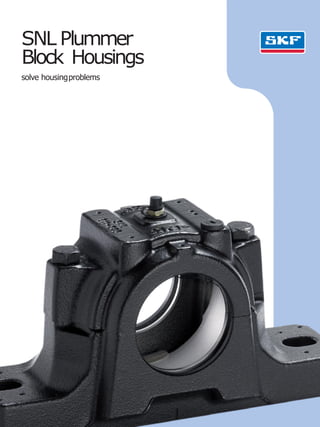
- 1. SNL Plummer Block Housings solve housingproblems
- 2. The SKF brand now stands for more than ever before, and means more to you as a valued customer. While SKF maintains its leadership as a high-quality bearing manufacturer throughoutthe world, new dimensions in technical advances, product support and services have evolved SKF into a truly solutions-oriented supplier, creating greater value forcustomers. These solutions enable customers to improve productivity, not only with breakthrough application-specificprod- ucts, but also through leading-edge design simulation tools andconsultancy services, plant asset efficiency mainte- nance programmes, and the industry’s mostadvanced supply management techniques. The SKF brand still stands for the very best in rolling bearings, but it now stands for much more. SKF – the knowledge engineering company ProductinformationA 3 Fewer bearing replacementsand less maintenance 3 Plummer blockhousingshavemuch tooffer 3 SNL plummerblockhousingshave moretooffer 4 Onebasic design–manyvariants 6 Featuresandbenefits 8 Superior performance in allsectors B Recommendations 10 Bearing arrangement design 10 Bearings onadaptersleevesonstraight shafts 11 Bearings onadaptersleevesonstepped shafts 12 Bearings onwithdrawal sleeveson steppedshafts 13 Bearings oncylindrical seatsonstepped shafts 14 Standardseals 21 Specialseals 22 Endcovers 22 Locatingrings 24 Axial displacement using CARBtoroidal roller bearings in SNLhousings 26 Application advice fortrouble-free operation 28 Lubrication 32 Mounting 36 Mounting SNL housings withfour-lip seals 38 Mounting SNL housings withdouble-lip seals 40 Mounting SNL housings with V-ring seals 42 Mounting SNL housings with feltseals 44 Mounting SNL housings withlabyrinth seals 43 Mounting SNL housings withtaconite seals 48 Mounting SNL housings with oilseals Contents ProductdataC 50 Designations and housing data – general 50 Designations 50 Loadcarrying ability 56 Product tables 56 SNL plummerblockhousings for bearings onanadaptersleeve, metricshafts 68 SNL plummerblockhousings for bearings onanadaptersleeve, inchshafts 84 SNL plummerblockhousingsfor bearings with acylindricalbore 94 Sealingarrangements for SNLplummer blockhousings D Additional information 100 Other products fortrouble-free operation 100 High-performance, self-aligning standardbearings 101 For easymounting –adapterand withdrawalsleeves 102 Otherproducts 103 Otherbearinghousings 104 Conditionmonitoring equipment 106 SKF – the knowledge engineering company 2
- 3. Fewer bearingreplacements andlessmaintenance Plummer blockhousings have much to offer The mainbenefit of split plummerblock housings is their easyinstallation;preassem- bledshafts canbemountedin them.When thehousing basesare attachedtothebase plate,it is thenonly necessarytoplacethe housing capsin positionandtotighten the attachmentboltstocompletetheinstallation. Split plummerblockhousings availableon themarketaremainlyintended forself-align- ing ball bearings, spherical rollerbearings and CARBtoroidalroller bearings of ISODimen- sion Series 02,03, 22,23 and32. Theycan often befittedwith anumberof different seals.Many designs andvariants of split plummerblockhousings areavailable,making theuse of tailoredhousings unnecessaryand thus enabling cost-effective bearing arrange- mentstobemade. For manyyearsSKFhasbeenoneofthe leading producers of split plummerblock housings –synonymous with operational reliability, qualityandversatility. SNL plummer block housings have more tooffer SKFhasdevelopedthe SNL plummerblock housings tobethefirst choice for design, qualityandeconomy.This enablescustomers tokeepastepahead. SNLplummerblockhousings enablethefull service life potential of theincorporated bear- ings tobeexploitedwith less needfor main- tenance.This supports user’seffortstofurther reducemaintenancecosts.Amongother characteristics, thehousings areverystiff, making theminsensitive touncontrolled and excessivetightening of theattachmentbolts. Anotherbenefitis thewiderangeofdifferent types of standard seals to be fitted in the SNL plummerblockhousings. A 3
- 4. One basic design – many variants SNL plummerblockhousingsareprimarily intendedfor self-aligning ball bearings,spher- ical roller bearingsandCARBtoroidalroller bearings. Thehousingsaredesignedonthe ”buildingblock”principle toenableawider choiceofbearingsandsealsaswellasavariety ofmounting andlubrication methods. Abuilding block system The SKFassortment of SNL plummerblock housings canaccommodateshafts ranging from20 to160mmindiameter.These hous- ings,whichallsharethe samedesignfeatures, areavailablewith avarietyof seals. The standard rangealso includes anumberof options, liketappedholes for greasefittings andcondition monitoring sensors, tocreate analmostlimitlesscombination of variants. Housings are also availablefor bearings for largershaft diameters( † page 103). SNL plummerblockhousings aremade of high quality,greycast iron toprovidehigh tensilestrength. Forapplications whereadd- itional strength is required,housings made of spheroidal graphitecast ironare available. Several sealingoptions AnimportantadvantageoftheSNLplummer blockhousings is thattheycanbefitted with avarietyof seals.StandardSKFsealsinclude four-lip seals,V-ringseals,feltseals,labyrinth sealsandheavy-duty taconitelabyrinth seals with aradial labyrinth andendcovers.Other standardsealsare also availablefor SNL housings,but thehousinghastobemodified for thesealtobeeffective.These include oil sealsandheavy-duty taconitelabyrinth seals with anaxiallabyrinth. SNL plummerblockhousings aredimen- sionally interchangeablewiththeearlierSNH housings.Theirdimensionsconformto ISO113:1999. SNL plummerblock housing withsealingoptions 4
- 5. A 5
- 6. • Stiffdesign Insensitivetoover-tightening of theattachment bolts • Excellentheat dissipation Lowers bearing operatingtemperature Extends relubricationintervals Increasesthe service life of the bearings,seals andlubricant Relubricationfacilityasstandard• Drilled andtappedholes for greasefittings Avoids mixing capsandbases,enablestraceability• Capsandbases individually marked Enables quickeradaptationof astandardhousing toanapplication• Dimplescastinto the housing toidentify drillinglocations • Simplemounting • Additionalseals Centre lines arecastinto the housing baseto simplify the alignmentprocess Several sealing options, toextendbearing servicelife in harshoperating environment • Greaseguidingsystem Guides greasedirectly tothesideofthebearing Features andbenefits The SKFassortment of SNL plummerblock housings is characterized byanumberof advantages,including high load carrying capacityandmachining quality.Inaddition, SNL housings incorporate unique features that aredesignedtoimprove theperformance andincreasetheservicelife of yourapplication. Stiffdesign The housing baseis reinforced with ribs andextra material aroundtheattachmentholestoaddstrength andpreventdeformationof thebase.Theattachment bolts canbepreloaded tolocate thehousing and preventdeformation of thehousing baseandbore. Excellentheatconduction Additional ribs ontheunderside ofthebaseimprove heatflowfromthebearingouterring tothesupport surface.Bearingsin anSNL housing run 5–10% coolerthanthebearingsin otherhousings. Relubricationmadesimple StandardSNL housings havetwotappedholes in the capfor thegreasefitting. Theyareprotectedbyplas- tic plugs.The locationof thegreasefitting is deter- minedbythebearing. Ifthebearinghas aW33 groove,install thefitting in themiddleof thehousing. Otherwise,putthefitting in theother hole sothat greasewill enterthebearingfromtheside. Caps and bases individuallymarked The housing baseandcaparematchedduringman- ufacture andarenotinterchangeable with thecaps andbasesof other housings. Topreventanymis- matches,aunique serialnumberis markedonboth thehousing capandbase. Greaseguidingsystem Whenlubricating fromthetop,this feature guides freshgreasefromthefitting totheside of thebearing. This appliesin particularfor lubricating self-aligning ball bearingsand CARBbearings. 6
- 7. Dimples tolocateaccessories SNL housings havedimplescastinto thehousingcap toshowwhereconditionmonitoring sensorscanbe mountedfor maximumeffectiveness. Simplemounting Tosimplify mounting andmakealignment more accurate,lines indicating thecentre of theboreand thecentre of thebasearecastinto thehousing. Mounting instructions,included with eachsealpack, providevaluableinstallation tips. High speedseal The SKFfour-lip, lowfriction sealwasdeveloped specifically forSNL housings. This highly effective seal,whichcanaccommodatespeedsupto13m/s, is easytoremoveandinstall. A 7
- 8. Superior performance in allsectors High load carrying capacity,robust design, accuratelymachinedsurfaces andsimplified installationmakeSKFhousings thefirstchoice for machinemanufacturers andendusers. Applications • Mineventilators • Exhaustandfresh airfans • Flue gasfans • Emergency powersupplygenerator flywheels • Transmissions • Beltdrives • Impactandhammermills Customerdemands • Robustdesign • Nobreakdowns • Extremelyeffectiveseals • Long maintenanceintervals • Conditionmonitoring facilities • Fastandeasymountingand dismounting Another reason whySKFhousings areso popular is becauseknowledgeableconsumers knowthat high qualitycomponentscansig- nificantly reduceoperatingcosts–that includes everythingfrommaintenance,energy consumption,lubricant consumption and downtime. Solution 8
- 9. A 9
- 10. Bearingarrangementdesign SNL plummerblockhousings aretypically usedwith self-aligning ball bearings, spher- ical roller bearings or CARBtoroidalroller bearings fittedonstraight or steppedshafts; thebearings canbemounted onadapteror withdrawal sleevesor directly oncylindrical shaft seats.These housings canalso beused with otherbearing typesiftheyarewithin the correct DimensionSeries. 1. Bearings on adapter sleeves on straight shafts Advantages • Drawnround bar(toleranceh9)canbe usedwithoutmachining. • Maximumshaftstrength asthereisno weakening byshoulders orreliefs. • Bearings canbemountedatanyposition ontheshaft. • Mounting force, i.e. the force required to drive the bearing onto the sleeve, is 40 % lessthanwithothershaftsbecausethere is only oneslidingsurface. • Bearing radial clearance canbeadjusted (within limits)during mounting tomeet applicationdemands. Applications • Bearing arrangements for relatively long shafts wheremorethantwobearingsare required forsupport. • Bearing arrangements wheremachine componentsaremountedusingwedging or tensioning componentsthat donot require theshaft tobemachined. • Bearing arrangements wherethe final positionof thebearing cannot beaccurately determined. Bearings on adaptersleeveson straightshafts 12EK SNL5 22EK 213CCK23EK SNL6 13EK 223EK232CCK C 23K222 EK BS2-22-2CSK C 22K C 32K 10
- 11. 2. Bearings on adapter sleeves on stepped shafts Advantages • The bearing positionontheshaftisaccur- atelydetermined bytheabutmentring. • Othercomponentsontheshaft canbe axiallylocatedbythebearing onitssleeve viaspacersleeves. • Easydismounting asthebearing innerring is in contactwith the abutmentring. • Bearing radial clearance canbeadjusted (within limits)during mounting tomeet applicationdemands. Applications • Bearingarrangementsattheendofashaft. • Bearing arrangements wherefrequent mounting anddismounting arerequired. Bearings on adaptersleeveson steppedshafts 12EK SNL5 22EK 213CCK23EK SNL6 13EK 223EK232CCK C 23K222 EK BS2-22-2CSK C 22K C 32K B 11
- 12. 3. Bearingson withdrawal sleeves on stepped shafts Advantages • The bearing positionontheshaftisaccur- atelydetermined bytheshaftshoulder. • Othercomponentsontheshaft canbe axiallylocatedbythebearing onitssleeve viaspacersleeves. • Easydismounting using awithdrawalor hydraulicnut. • Bearing radial clearance canbeadjusted (within limits)during mounting tomeet applicationdemands. Applications • Bearingarrangementsattheendofashaft. • Bearing arrangements wherefrequent mounting anddismounting arerequired. Bearings on withdrawalsleeveson steppedshafts 12EK SNL5 22EK 213CCK23EK SNL6 13EK 223EK232CCK C 23K222 EK BS2-22-2CSK C 22K C 32K 12
- 13. Bearings on cylindrical seatson steppedshafts 4. Bearings on cylindrical seats on stepped shafts Advantages • The axialload carrying capacityof the bearings (inbothdirections) is notlimited byasleeve. • The residual bearing internalclearance is determinedbythetolerance of the shaft seatsothere is no dangerof radially preloading the bearing duringmounting. • The bearing positionontheshaftisaccur- atelydetermined bytheshaftshoulder. • The bearing canbesupported byother componentsviaspacersleeves. • The shaftdiameteratthebearing position ismaximized. Applications • Bearing arrangements wherelargenum- bersof bearings havetobemounted. • Bearing arrangements wherelargeshock loads canoccur. SNL2 12 E 22E 222E 213CC23E SNL3 13E 223CC232CC C22 C32 C23BS2-22-2CS B 13
- 14. Standard seals Animportant advantageof SNL plummer blockhousings is that theycanbefittedwith different typesof seals.StandardSKFseals include split four-lip seals,V-ring seals,felt seals,labyrinth seals andheavy-duty“taco- nite”seals with aradial labyrinth. The seals areeasytoinstall andaresuppliedseparately. All thestandardseals,aswellastheseals for use with oil lubrication, areshownin table 1, with anoverviewof theseal type, its designfeaturesandsuitabilityforvarious operatingconditions. Detailedinformation aboutstandard andspecial seals canbefound onpages16 to21. Table1 Sealselection 1)Deliveredas acomplete unitonly,i.e.housingswith seals,SNL ..TURU. Oil seals canbeorderedseparatelyas sparepartsonly 2)Seetable 2 onpage 15 toconvertperipheral speeds to rotationalspeeds 3)WhentheV-ring isaxially supported 4)Ifappropriatecomponents areused;i.e. ASNA..Vendcover at theendof ashaft 5) WhentheV-ring of thelower sealis mountedinboard TSN..L TSN..A TSN..C TSN..S TSN..ND TSN..U1) Internalconditions Temperature,°C –40 to+100 –40 to+100 –40 to+100 –50 to+200 –40 to+100 -40to +200 Temperature,°F –40 to+210 –40 to+210 –40 to+210 –60 to+390 –40 to+210 -40to +390 Peripheral speed,m/s2) up to13 up to7 up to4 ++ up to12 ++ above73) Misalignment,degrees 0,5 to1 1 to1,5 up to0,5 up to0,3 up to0,5 up to1 Greaselubrication ++ ++4) - + + Oillubrication -- -- -- -- -- ++ Lowfriction ++ ++ - ++ + ++ Axialshaftdisplacement ++ - ++ + + - Verticalarrangement + ++5) -- -- - -- Replacement ++ - + - - - Externalconditions Dust ++ + + + ++ - Fineparticulate ++ + - + ++ + contaminants Coarseparticulate + - - + ++ + contaminants Abrasivecontaminants + -- + ++ ++ ++ Liquids whensprayed + + - -- ++ - Directsunlight + -- ++ ++ ++ ++ Symbols: ++verysuitable +suitable -limited suitability -- unsuitable 14
- 15. Table2 Rotational speeds corresponding to peripheralspeeds Shaftdiameter at the seallip Rotational speedscorresponding to peripheral speedsof 1) da,db 2m/s 4m/s 7m/s 8m/s 12m/s 13m/s mm r/min 20 1910 3820 6680 7640 11460 – 25 1530 3060 5350 6110 9170 – 30 1270 2550 4460 5090 7640 8280 35 1090 2180 3820 4370 6550 7090 40 950 1910 3340 3820 5730 6210 45 850 1700 2970 3400 5090 5520 50 760 1530 2670 3060 4580 4970 55 690 1390 2430 2780 4170 4510 60 640 1270 2230 2550 3820 4140 65 590 1180 2060 2350 3530 3820 70 550 1090 1910 2180 3270 3550 75 510 1020 1780 2040 3060 3310 80 480 950 1670 1910 2860 3100 85 450 900 1570 1800 2700 2920 90 420 850 1490 1700 2550 2760 95 400 800 1410 1610 2410 2610 100 380 760 1340 1530 2290 2480 110 350 690 1220 1390 2080 2260 115 330 660 1160 1330 1990 2160 120 320 640 1110 1270 1910 2070 125 310 610 1070 1220 1830 1990 130 290 590 1030 1180 1760 1910 135 280 570 990 1130 1700 1840 140 270 550 950 1090 1640 1770 145 260 530 920 1050 1580 1710 150 250 510 890 1020 1530 1660 155 250 490 860 990 1480 1600 165 230 460 810 930 1390 – 175 220 440 760 870 1310 – 1) da:shaftdiameterfor bearings onanadaptersleeve. db:shaftdiameterfor bearings onastepped shaft B 15
- 16. Four-lipseals With shaft speedscontinuously increasing, there wasaneedfor asealing solution that could accommodatehigher speedswith the samehigh level of performance that the SKF double-lip seal could provideatlowerspeeds. Tomeetthat need,SKFdevelopedarobust, easy-to-mount four-lip seal ( † fig. 1)that canaccommodateperipheral speedsupto 13 m/s.This four-lip seal ismadefromaspe- cially formulated thermoplastic elastomer.Itis manufacturedusing aunique processthat improvesthefinish of thecontact surfaces so that there is less friction andheatgenerated bytheseal. These four-lip seals,which are designed for greaselubrication, canaccom- modatespeedsupto13 m/sevenif thehous- ing uses agreaseescapehole (suffix V).The seals aresplit so that theycanbeinstalled easily. The permissible angular misalignment for shaft diameters≤100 mmis approximately 1°andapproximately0,5°for largershafts. The seal counterface ontheshaft should be groundandthesurface roughnessRashould not exceed3,2 µm.The recommended shaft tolerance is h9.The axialmovementof the shaft relative tothehousing is not limited whenfour-lip seals areused.Thepermissible operatingtemperaturerangefor the seal is between–40 and+100°C(–40to+210°F). The seals areavailablefromsize TSN 507 L uptoandincluding sizeTSN532 L. Eachpackageof four-lip sealscontains two seals.Consequently,whenusing anendcover, oneseal canbekeptasaspare.Four-lip seals areidentifiedbythedesignation prefix TSN followed bythesize identification andthesuf- fixL,e.g.TSN511L. V-ring seals V-ring seals( † fig. 2)are two-piece seals thatconsistofaV-ringandagalvanized,sheet steelsealingwasher.Arubberlip,vulcanizedto thesealing washer,fits into theseal groovein thehousing.The V-ring fits tight ontheshaft andsealsaxiallyagainstthe washer.Asit is turning with theshaft,the V-ring actsasa flinger.These veryefficient sealsaretypically usedin difficult applicationse.g.where there arehighspeedsor roughfinished shafts. They canaccommodateperipheral speedsin excess of 7 m/sif theV-ring is prevented frommov- ing or lifting fromtheshaft byasupport ring. Recommendeddimensionsfor appropriate support rings (foraxial andradial location)are providedin table3. NOTE: Supportrings cannotbeusedforsizes between205 to211 and306 to314 dueto limited spacebetweentheshaft andhousing shaftbore. The permissible angular misalignmentfor V-ring seals is approximately1,5°fora 50 mmshaft decreasing toapproximately1° for shaft diameters≥150 mm.The axial movementof theshaft relative tothehousing is limited to±1mmfor shaft diametersupto 65 mm,toapproximately+/-1,2 mmfor 70-100 mmshaft diametersandtoapproxi- mately+/-1,5mmfor largershaftdiameters. Each packageof V-ring seals contains two seals.Consequently,whenusing anendcover, oneseal canbekeptasaspare.V-ring seals areidentifiedbythedesignation prefix TSN followed bythesize identification andthesuf- fixA,e.g.TSN511A. V-ringseal Fig.2 Four-lipseal Fig.1 16
- 17. Locationof theV-ring Peripheral speedupto7m/s Peripheralspeed 7 to12m/s Table3 Recommendeddimensionsforsupportrings forV-ring seals Shaft diameter V-ring Designation VAR CR da,db 1) Dimensions d1 d2 B B1 B2 D Grub screw to A G1 DIN913 mm mm – – 20 20 27,2 5 8,5 3,5 30 2,5 M3 3 ¥5 20VAR CR400200 25 25 32,1 5 8,5 3,5 35 2,5 M3 3 ¥5 25VAR CR400250 30 30 37,2 5 8,5 3,5 40 2,5 M3 3 ¥5 30VAR CR400300 35 35 42,2 5 8,5 3,5 45 2,5 M3 3 ¥5 35VAR CR400350 40 40 49,1 7 11,5 4,5 53 3,5 M4 4 ¥5 40VAR CR400400 45 45 54 7 11,5 4,5 58 3,5 M4 4 ¥5 45VAR CR400450 50 50 59,1 7 11,5 4,5 63 3,5 M4 4 ¥5 50VAR CR400500 55 55 64,1 7 11,5 4,5 68 3,5 M4 4 ¥5 55VAR CR400550 60 60 69,1 7 11,5 4,5 73 3,5 M4 4 ¥5 60VAR CR400600 65 65 74,1 7 11,5 4,5 78 3,5 M4 4 ¥5 65VAR CR400650 70 70 81 9 15 6 84 4,5 M5 5 ¥6 70VAR CR400700 75 75 86 9 15 6 89,5 4,5 M5 5 ¥6 75VAR CR400750 80 80 91 9 15 6 94,5 4,5 M5 5 ¥6 80VAR CR400800 85 85 96 9 15 6 100 4,5 M5 5 ¥6 85VAR CR400850 90 90 101 9 15 6 105 4,5 M5 5 ¥6 90VAR CR400900 95 95 106 9 15 6 109 4,5 M5 5 ¥6 95VAR CR400950 100 100 111 9 15 6 115 4,5 M5 5 ¥6 100VAR CR401000 110 110 122,9 10 17,5 7,5 128 5 M6 6 ¥8 110VAR CR401100 above12m/s 115 115 127,4 10 17,5 7,5 133 5 M6 6 ¥8 110VAR CR401100 125 125 138,1 10 17,5 7,5 143 5 M6 6 ¥8 130VAR CR401300 135 135 147,5 10 17,5 7,5 153 5 M6 6 ¥8 130VAR CR401300 140 140 152,9 10 17,5 7,5 158 5 M6 6 ¥8 140VAR CR401400 145 145 158,1 10 17,5 7,5 163 5 M6 6 ¥8 150VAR CR401500 155 155 167,5 10 18,5 8,5 173 5 M6 6 ¥8 150VAR CR401500 165 165 179,9 10 18,5 8,5 185,5 5 M6 6 ¥8 170VAR CR401700 175 175 189,3 10 18,5 8,5 195 5 M6 6 ¥8 170VAR CR401700 120° G1 A d1 D B B2 d2 B1 7–12m/s >12m/s 1) da:shaftdiameterfor bearings onanadaptersleeve. db:shaftdiameterfor bearings onastepped shaft B 17
- 18. Fig.3b Felt ringseals Feltring seals ( † fig. 3)aresimple,efficient greaseseals that canaccommodateperiph- eral speedsupto4 m/s.These seals can accommodatehigher speeds,butbeyond 4 m/s,asmall gapformsbetweenthefeltand shaft, transforming thecontact seal into a non-contact, gap-typeseal. Inapplications wherebearings aremount- edonastraight shaft with adaptersleeve, split felt ringseals aretypicallyused ( † fig. 3a). The felt is impregnatedwith oil. Toinstall theseseals, around rubber cordis firstinsertedintothesealgrooveinthehous- ing.Then, with thefelt inserted in thelight alloyhalf-rings, thehalf rings areinstalledin theseal groove.The rubbercordpreventsthe rings fromturning. The permissible angular misalignmentfor feltring seals isapproximately0,5°.Theseal counterface ontheshaft should beground andthesurface roughnessRashould not exceed3,2µm. The axialmovementof theshaftrelative to thehousing is not limited whenfelt seals are used. Eachpackageof felt ring seals containstwo seals.Consequently,whenusing anend cover, oneseal canbekeptasaspare.Feltringseals areidentifiedbythedesignation prefix TSN followed bythesize identification andthesuf- fix C,e.g.TSN 511C. High temperatureapplications For applications where spherical roller bear- ingsor CARBtoroidal roller bearingsoperate continuously athigh temperatures,upto +250°C(480°F),SKFgraphitedFSB seals should beused.These sealsaremadeofalu- miniumboronsilicateandcanaccommodate speedsupto2m/s. Feltring seals canbesupplied withanFSB insert. The round rubber cords usedwith these seals arereplacedwith afluoro rubber cord.These seals areidentifiedbythe suffix CB,e.g.TSN511CB. Feltstrips Ifthebearings aretobeinstalledonastepped shaft with acylindrical seat(sizes 205 to218 inclusive),loose felt strips ( † fig. 3b) canbe used.The strips are170 mmin length.They should becut totheright length andprior to installation,theymustbesoakedin hot oil for afewminutes.Then, theycanbeinstalled directly intotheseal groove.The feltstrips are designatedFS170. High temperatureapplications For high operatingtemperatures,upto +250°C(480 °F),SKFgraphitedstrips canbe supplied. Theyshould becut totheright length.Theycanbeinstalleddirectly into the sealgroove. ContactSKFfor correctdesignation. Feltringseal Fig.3a Feltstrips Felt ringseal Sealsmadeof fluoro rubber giveoffhaz- ardous fumeswhenexposedtoextreme temperaturesabove300 °C(570°F). Therefore, reviewandfollowthesafety recommendationsmentioned in thesec- tion “Sealmaterials”in theGeneralCata- logue 6000, onpage143. 18
- 19. Labyrinth seals For applications wherethere are high speeds and/orextremetemperatures,SKFrecom- mendsusing alabyrinth typeseal ( † fig. 4). The standard labyrinth typeseal is called a labyrinth ring. Labyrinth rings consist of a metalring with twostepsarranged radially. Onestepfits in the seal grooveinthehousing toformagaptypeseal. The otherstepforms agaptypeseal with theoutside of thehous- ing.Ahollow,silicone rubber cordsupplied with theseal holds thelabyrinth ring in place ontheshaft. The standard labyrinth seals canaccom- modateapproximately0,3°of angular mis- alignment andoperatingtemperaturesrang- ing from–50 to+200°C(–60to+390°F). Whenlabyrinth seals areused,axial move- mentoftheshaftrelative tothehousing isnot limited.The recommendedshaft tolerance is h9. Labyrinth rings aresupplied singly. For through-shaft applications, tworings should beordered.Alabyrinth ring is identifiedbythe designation prefix TSN followed bythe size identification andthesuffixS,e.g.TSN511 S. Taconite heavy-dutyseals Taconiteis averyfine-grained mineral which is extremelydifficulttoseal against.For bear- ing arrangements which mustoperateunder veryarduous conditions such asthose encounteredin mining, labyrinth seals, which canberelubricated, arerecommended,as greaseenhancesthesealing effect and extendstheserviceability of theseals.SKF hasdevelopeddifferent designs of these heavy-dutyseals (which canseal against taconite,hence thename)that canbesup- pliedforusewithSNLhousings. Onetaconiteseal design( † fig. 5)is based onaradial labyrinth seal andfits standard housings. AV-ring seal mountedontheshaft sealsagainstthenon-rotatingpartoftheseal, which is insertedin theseal groove andpre- ventscontaminants frompenetrating tothe bearing when theseal is relubricated. This greaseis supplied viaagreasefitting in the non-rotating part of theseal. Angular mis- alignments of the shaft of uptoapproximately 0,5°arepossible.The permissible operating temperaturerangefor theseal isbetween –40 and+100°C(–40to+210°F). The axial movementof theshaft relative to the housing is limited for this type of taconite seal to±1mmfor shaft diametersupto 65 mmandtoapproximately±1,2mmfor sizes upto100 mmand±1,5mmforlarger shaft diameters.The recommended shaft tolerance ish9. These seals aresupplied singly so that for housings usedonthrough shafts, itis neces- sary toorder twoseals.The seal is identified bythedesignation prefix TSN followed by thesize identification andthesuffix ND,e.g. TSN 511ND. The seconddesignof taconiteseal ( † fig. 6)is basedonalabyrinth seal with thelabyrinth stagesarranged axially.The seal is relubricated vialubrication holes andfit- tings in thehousing cap.The positions for the holes aremarkedbydimplesin thecasting. The permissible misalignment of the shaft relative tothehousing for this seal is approxi- mately0,5°.The operatingtemperaturerange is from–40 to+250°C(–40to480 °F).Axial movementof theshaft relative tothehousing is also limited.The recommended shaft toler- anceish9. Fig.4 Labyrinthseal Fig.5 Taconiteheavy-duty sealwitha radial labyrinth Fig.6 Taconiteheavy-duty sealwithan axial labyrinth B 19
- 20. These seals require that avariant of the standardhousing isordered,eithersuffixTfor housing usedwith endcoverwhenlubrication ononlyonesideofhousing isrequired orsuf- fixTDforthrough shaftwhenlubricationpos- sibilitiesisrequired onbothsides ofthehous- ing.The sealsareavailablefromsize 515-612. The seals are supplied separately andis identifiedbythedesignation prefixTSN followed bythesize identification andthesuf- fixNC,e.g.TSN515-612 NC. The third variant of theTaconiteseal has thesamedesignastheTaconiteheavy-duty seal with anaxial labyrinth but includesan V-ring seal ( † fig. 7)andrequires the same modified housing preparedfor lubricationon oneor twosides of thehousing, e.g.suffix T orTD,asthesecondseal variant.The sealis availablefromsize 515-612. The seals are supplied separatelyandis identifiedbythe designation prefix TSN followed bythe size identification andthesuffix NB, e.g.TSN 515-612NB. Seals for oil lubrication Toretainoil in anSNL housing andprevent leaks,SKFhasdevelopedaU-designlabyrinth seal ( † fig. 8).These seals, which require a modified housing, consist of twoparts:asta- tionary U-shaped platethat is boltedtothe housing, andasteel labyrinth ring that is mountedonthe shaft. Twohollow,silicone rubber cordsinserted betweentheloose fit- tinglabyrinth ring andshaft, keepthering in placeandpreventoil fromescapingalong theshaft. Tokeepthetwoseal partstogether, aretaining ring is mounted onthelabyrinth ring. These oil seals donot limit axial move- mentoftheshaftrelative tothehousing.The recommended shaft tolerance for these seals isg7,buth9isacceptable. Modified SNL housings for oil lubrication aresupplied togetherwith seals.Thehousings with seals areidentifiedbydesignation suffix TURU,e.g.SNL 524 TURU.Special endcov- ers,designation ASNH ..R,mustbeordered separately. SNL..TURU housings arepronetooverfill- ing with oil. This is duetothelimited size of theSNL sump.Forthis reason,it is very important not toexceedtherecommendedoil level ifleaksaretobeavoided( † table3 on page30). Oilseal Taconiteheavy-duty sealwithan axiallabyrinth and an V-ringseal Fig.8Fig.7 SONL housings for oil lubrication Aspart of the SNL assortment,SKFhasafull line of SONL housings, specifically designed foroil lubrication.Availableforshaftdiameters ranging from75 to240 mm,thesehousings arenot aspronetooverfilling asSNL hous- ings. Otheradvantagesof the SONL housing include • a15 %largeroilsump(reservoir) • cooling finsinsidethecasting forimproved heatdissipation. ForadditionalinformationaboutSONLplum- merblockhousings, † SKFpublication 6111 ”SONLplummerhousings –designed for oil lubrication.” 20
- 21. Specialseals For applications that require special seals,SKF recommends ordering housings in theSNL 2 series rather thanthose in the5 or 6 series. Housings in the SNL 2 series havealarger bore(Db)andcanaccommodateawider choice of sealdesigns. Special seals are not normally supplied by SKF. Therefore, relevant seal groove dimen- sions are providedin table4. Table4 Seal groovedimensions Housing Dimensions Size A3 A4 A5 A6 Db Dc – mm SNL205 44 5 7,5 10 36,5 44,5 SNL206-305 54 5 7,5 10 46,5 54,5 SNL207 58 5 8 11 56,5 64,5 SNL208-307 61 5 8 11 62 70,5 SNL209 59 5 9 12 67 75,5 SNL210 64 5 9 12 72 80,5 SNL211 69 5 9 12 77 85,5 SNL212 79 5 9 12 87 95,5 SNL213 82 5 9 13 92,5 101 SNL215 87 5 9 13 102,5 111 SNL216 92 5 9 13 108 116,5 SNL217 97 5 9 13 112 120,5 SNL218 112 5 9 13 120 128,5 SNL505 45 5 7,5 10 31,5 39,5 SNL506-605 55 5 7,5 10 36,5 44,5 SNL507-606 59 5 8 11 46,5 54,5 SNL508-607 62 5 8 11 51,5 59,5 SNL509 60 5 9 12 56,5 64,5 SNL510-608 65 5 9 12 62 70,5 SNL511-609 70 5 9 12 67 75,5 SNL512-610 80 5 9 12 72 80,5 SNL513-611 83 5 9 13 77 85,5 SNL515-612 88 5 9 13 87 95,5 SNL516-613 93 5 9 13 92,5 101 SNL517 98 5 9 13 97,5 106 SNL518-615 113 5 9 13 102,5 111 SNL519-616 116 6 10 14 131 141 SNL520-617 131 6 10 14 137,5 147,5 SNL522-619 143 6 10 14 147,5 157,5 SNL524-620 151 6 11 15 157,5 167,5 SNL526 156 6 11 15 167,5 177,5 SNL528 171 6 11 15 177,5 187,5 SNL530 189 6 11 15 192,5 202,5 SNL532 201 6 11 15 202,5 212,5 A4 A6 A5 A3 Db DC 1° B 21
- 22. End covers Housings mountedattheendof ashaft shouldbefittedwithanendcoverthatfitsinto thesealgroove( † fig. 9).Detailsoftheper- missible length of theshaft endcanbefound in table 5. End covers, which areplastic, are suitablefor operatingtemperaturesranging from–40 to+110°C(–40to+230°F). For applications wheretemperatures exceed110 °C(230°F),steel endcovers should beused.These canbecut fromsheet steel andplacedin the seal groove.Useahol- low silicone rubber cordtohold the coverin place.Sealgroovedimensions areprovidedin table4 onpage 21. The standard plasticendcoverisidentified bythedesignation prefix ASNH followed by thehousing size identification,e.g. ASNH511-609. Locatingrings The width ofthebearing seatinSNLhousings ismachinedinsuch waythatitcanaccommo- datebearings in the locating aswell asin the non-locatingposition. The locating bearing,which locatesthe shaft axiallyin bothdirections, mustbe secured in thehousing onbothsideswith alocating ring ( † fig. 10). Inmostcases,thenon-locating bearing is free tomoveaxiallyin thehousing toaccom- modatethermal expansionof theshaft. How- ever,CARBtoroidalroller bearings are an exception.These bearings accommodateaxial displacement internally andmustthereforebe secured in thehousing, onbothsides,with alocatingring. Locating rings areidentifiedbythe desig- nation prefix FRB followed byfigures indicat- ing thewidth/outsidediameterinmillimetres, e.g.FRB11.5/100. Housing withan endcover Fig.9 Housing witha locatingring atboth sides of thebearing Fig.10 22
- 23. Table5 Premissible length of shaft end Dimensions Widest bearingthatfits thehousingHousing Size Designation Dimensions 1) ba bc Ca B bb – mm – mm SNL205 18 24 25 22205E 18 17 SNL206-305 20 29 32 2305E 24 19 SNL207 23 32 34 22207E 23 20,5 SNL208-307 26(22) 33 39 2307E 31 24,5 SNL209 25 32 30 22209E 23 22,5 SNL210 28(24) 35 41 22210E 23 23,5 SNL211 30(25) 37 44 22211E 25 25 SNL212 33(26) 42 48 22212E 28 27 SNL213 35(30) 45 51 22213E 31 29,5 SNL215 37(30) 47 56 22215E 31 30,5 SNL216 39(33) 50 58 22216E 33 33,5 SNL217 40(35) 52 61 22217E 36 36 SNL218 45(35) 60 65 23218CC/W33 52,4 44,2 SNL505 18 24 25 22205EK 18 17 SNL506-605 20 29 32 2305EK 24 19 SNL507-606 23 32 34 2306EK 27 21,5 SNL508-607 26(22) 33 39 2307EK 31 24,5 SNL509 25 32 30 22209EK 23 22,5 SNL510-608 28(24) 35 41 22308EK 33 26,5 SNL511-609 30(25) 37 44 22309EK 36 29 SNL512-610 33(26) 42 48 22310EK 40 32 SNL513-611 35(30) 45 51 22311EK 43 33,5 SNL515-612 37(30) 47 56 22312EK 46 36 SNL516-613 39(33) 50 58 22313EK 48 38 SNL517 40(35) 52 61 22217EK 36 36 SNL518-615 45(35) 60 65 22315EK 55 42,5 SNL519-616 47(40) 61 68 22316EK 58 46 SNL520-617 51(45) 69 70 23220 CCK/W33 60,3 50,2 SNL522-619 61 75 80 23222 CCK/W33 69,8 55,9 SNL524-620 65 79 86 23224 CCK/W33 76 60 SNL526 65 81 90 23226 CCK/W33 80 63 SNL528 70 89 98 23228 CCK/W33 88 68 SNL530 80 98 106 23230 CCK/W33 96 74 SNL532 85 104 114 23232 CCK/W33 104 80 Ca B bb ba bc Ca B bb ba bc 1)The dimensionbasuitsall appropriatebearings,with two exceptions: 1. For self-aligning ball bearings in the12 series, values between brackets aresuitable fortotalbearing innerringseat 2. For non-locatingbearing arrangements, in particular for bearings with thewidest possible width (seetable),thevalues for bamustbecorrespondinglyadjusted (reducedor increased) whenthebearing is notmountedcentrally ( † page 24) B 23
- 24. Axial displacement using CARB toroidal roller bearings in SNL housings Axial displacement reducesclearance in a CARBbearing.Asaresult, thepermissible axial displacement dependsontheclearance in thebearing after mounting.Insufficient radial clearance,combinedwith axial dis- placement,could actually result in apreload condition that causes the bearing tofailpre- maturely.Seegeneral cataloguefor calcula- tion of permissible axialdisplacement. Even if clearance is sufficient, axial dis- placementin aCARBbearing is limitedbythe distancethe inner ring canmovebyanyone of thefollowing • rollers starttobeexposedononeside of thebearing • locknut/locking washer fouls therollers andcage • typeofseal. Toavoidthe rollers andcageassemblyfrom contacting thelock nut/ washer,bearings in theC22 Kseries, uptoandincluding size 22, should beusedwith aspecial adaptersleeve that hasanarrow slot andaself-locking KMFE nut.These sleevesareidentifiedbythe suffixE,e.g.H311 E( † fig. 11). Forbearings intheC22 KandC32 Kseries fromsize 24 andabove,sleevesaresupplied withaKMLnutindicatedbysuffixL in the sleevedesignation, e.g.H 2324L. CARB toroidal roller bearing on a stepped shaft and an adapter sleeve incorporating a self-lockingKMFEnut Fig.11 24
- 25. Applicationadvicefortrouble-free operation Conditionmonitoring is recommended for SNL plummerblocks,particularly if theyare fittedtomachineswherebearing failures wouldcauseproduction stoppages.The early recognition andtrending of thedegradationof themachineandmachineparts makeit pos- sible toanalysetheroot causeandtobeable toplan for corrective maintenanceactions beforetheyareneeded. Extensivemonitoring experienceanda knowledge of thedynamicbehaviour of machines,machinecomponentsandbearings wherethere is incipient damageenablesSKF torecommendtwopowerful signalprocessing techniques that canbeusedfor condition monitoring. Vibration velocity The RMS (rootmeansquare)of thevelocity ofvibrationsinthefrequencyrange10Hzto 1kHzhasbeenusedwithgreatsuccessto measure phenomenasuch asimbalance,mis- alignment,resonanceetc.Highlevelsof vel- ocityvibrationcanbegeneratedbypoor machine conditions suchasimproperclear- ances,imbalance,misalignment,weakfoun- dations,bentrotors,out-of-round, belt prob- lemsor damagedfanblades.The ISO Standard10816-1:1995 contains recom- mendationsfor referencevaluesfor theRMS velocityvaluesmeasuredondifferent classes ofmachinesandmachineparts.Theserecom- mendationsprovideaclear andquantifiable measure for thechangesinmachine condition. Vibration velocityexpressedasanoverall RMS valuein the10 Hz to1 kHzfrequencyrange providesminimalinformation ondefectsin rolling elementbearings or gearmeshprob- lems.These typesof defectcannowbeeasily detectedbyenveloped accelerationin the higher frequencyranges. SKF Multilogonline systemIMx-T SKF MachineCondition Transmitters(MCT) SKF Micrologseries datacollectors/ analysers 26
- 26. Envelopedacceleration Bearing defectscanbeeasilyrecognizedby measurementandanalysis of anenveloped accelerationsignal of thehigher frequencies generatedbytheimpactsignals typicalofroll- ing bearing defectsandgearteethproblems. This technique hasproventobeextremely reliablein the detection of incipient bearing defects.The low frequencies generatedby imbalance,misalignment etc.arenot meas- ured anddiagnosed within theenveloped accelerationprocess. • Conditionmonitoring anddiagnosiswith permanentlyinstalledmonitoring systems The SKFMultilog online systemIMx-T is thenextgenerationof powerful, cost- effective solutions for avarietyof condition monitoring applications. Togetherwith SKF@ptitudeObserver software,Multilog IMx-T providesacompletefor early fault detection andprevention, automaticadvice for correcting existing or impendingcondi- tions andadvancedcondition basedmain- tenancetoimprovemachinereliability, availability andperformance. SKF’sMachine ConditionTransmitters (MCT)deliver addedvalue toessentialpro- duction equipmentbyproviding vital infor- mationonbearing performance that helps maximize potential machineutilization. Highly cost-effective, using MCTsmean potential problemscanbespottedbefore theydeteriorate,somaintenanceand repairschedules canbeforecast andpro- duction arrangements cancontinue as planned. Each stand-alone monitoring devicemay bepermanentlymountedontoamachine, providing low-cost continuous monitoring of specific machine,gearandbearing performance parametersin pumps,fans, motorsandothergeneral-purpose machinery. • Conditionmonitoring anddiagnosiswith aportabledatacollectorandanalyser SKFoffers arangeof portablecondition monitoring hardware, designed toassess andreport ontemperature,oil condition, speed,bearing condition, shaft alignment, noise, vibration andmore.Whereameas- urementpointisdifficulttoaccess,perma- nently installedsensors canbeused.These canbeconnectedbycabletoaconnection boxaccessibletothe datacollector. SNL housings prepared for condition monitoring SNL housings haveappropriatepoints for sensors ( † fig. 1).Measuring point in posi- tion 1 is perpendicular tothe shaft, while position2 is paralleltotheshaft. Both points correspond toISO10816-1: 1995. The measurementpointinposition3isatapprox- imately45° tothe shaft axis.For enveloped acceleration,theangleof inclination of the measuringpointisofminorimportance. Measurement point in position2 should be usedonSNL housings wheretheload acts towardthebaseplate.The measuring pointin position1 is intended for ahousing that is hung fromits support or when theload acts awayfromthe baseplate. Housings withatappedhole forasensor in position3 canbesupplied onrequest.These housings aredesignatedwith the suffixSN. For additionalinformation aboutcondition monitoring andthemeasurementtoolsand systemsavailablefromSKF,contacttheSKF applicationengineeringservice. Measuring pointsforconditionmonitoring Position 1:Sensor position for accelerationenveloping ona verticalor hanging housing according toISO10816-1:1995 Position 3:This sensor positionis a compromise andcanbeusedforforces perpendicular or paralleltothe shaft centreline aswell asforcesexhibited against the measurementpoint Position 2:Sensor position for axial measurements according toISO10816-1:1995 Fig.1 B 27
- 27. Lubrication SNL plummerblocks canaccommodateeither greaseoroil asalubricant,butgreaseispre- ferred.Foroil, SKFrecommends SONLhous- ings. Whicheverhousing is used,thelubricant should beselectedbasedontheoperating conditions.Additionalinformationaboutlubri- cant selectioncanbefound in theSKFGen- eralCatalogue. Grease lubrication Inmostapplications, theinitial greasefill in anSNL housing will adequatelylubricatethe bearing until thenextplannedinspection. However,certain operatingconditions suchas high speeds,high temperaturesor heavy loads mayrequire morefrequent relubrica- tion. Table1 providesguideline valuesfor theinitial greasefill. Dependingonthe intended methodof relubrication, thefollow- ing greasefill percentagesfor thefree space in thehousing arerecommended • 40 %whenrelubricating fromthe side of thebearing • 20 %whenrelubricating through the annular grooveandlubrication holes in thebearing outerring. Ineithercase,the free spacein the bearing should becompletelyfilled with grease.For relubrication quantities, moreinformationcan befound in theSKFGeneralCatalogue.Six dimplescast into the topof thehousing cap indicates whereholes canbedrilled and tappedtoaccommodateagreasefitting.One dimpleoneachouter side of thecentral ridge indicates ahole locationtorelubricate the seal. SNL housings have,asstandard,two holes that havebeendrilled andtappedfor a greasefittingAH1/8-27 PTF ( † fig. 2).On anewhousing, theholes arecovered byplas- ticplugs.These plugsshould bereplacedwith thegreasefitting andthreadedplug supplied with thehousing. The hole in the middleof thecapshould beusedtorelubricate spheri- cal roller bearings with alubrication groove andthreeholes in theouter ring, designation suffix EorW33( † fig. 3).ForSNLhousings fromsize 524 having aneye-bolt in centre of housing thishole isdrilledinoneoftheboss- es( † fig. 4).Itshould benotedthat when spherical roller bearings are tobelubricated viatheouter ring, theshaft should berotat- ing.Ifouter ring relubrication is not possible, orif self-aligning ballbearings orCARBtoroi- dalrollerbearings areused,theotherstand- Relubricatinga bearing viathe outer ring and grease escapehole Fig.3Fig.2 Table1 Grease fitting AH 1/8-27PTF Greasequantities Housing Greasequantities Housing Greasequantities Size First fill 40% First fill 20% Size First fill 40% Firstfill 20% – g g – g g SNL205 25 15 SNL505 25 15 SNL206-305 40 25 SNL506-605 40 25 SNL207 50 30 SNL507-606 50 30 SNL208-307 60 35 SNL508-607 60 35 SNL209 65 40 SNL509 65 40 SNL210 75 45 SNL510-608 75 45 SNL211 100 60 SNL511-609 100 60 SNL212 150 90 SNL512-610 150 90 SNL213 180 110 SNL513-611 180 110 SNL215 230 140 SNL515-612 230 140 SNL216 280 170 SNL516-613 280 170 SNL217 330 200 SNL517 330 200 SNL218 430 260 SNL518-615 430 260 SNL519-616 480 300 SNL520-617 630 390 SNL522-619 850 530 SNL524-620 1000 630 SNL526 1100 700 SNL528 1400 900 SNL530 1700 1100 SNL532 2000 1300 28
- 28. ardhole should contain thegreasefitting ( † fig. 5)andthecentre hole should be plugged.Ifadifferent size greasefitting willbe used,adaptersthat fit into theexisting holes areavailable( † fig. 6),making rework unnecessary. Toimprovetheeffectiveness of relubrica- tion in applications whereV-rings areused, mountanadditionalV-ring insidethehousing ontheside wheregreaseisapplied.Doing this forces greasetotravelthrough thebearing to reachthe escapehole ontheoppositeside of thehousing. For this typeof sealing arrange- ment,SKFsupplies aV-ring andasplash platethat fits in theseal groovetocoverabit morethanthe tophalf of thehousing ( † fig. 7).TheV-ring andsplash platesetis identifiedbythe designation prefix ASNAfol- lowedbythehousing size identification and thesuffixV,e.g.ASNA511V. Inapplications wherebearings aremount- edonadaptersleeves,thegreaseshould be introduced fromtheoppositeside of thelock nut. Ifthehousing is locatedattheendof a shaft, greaseshould beappliedatthepoint closest totheendcover. Inapplications whereL or Cdesignseals areused,greasecannot escapeviatheseals. Therefore,iffrequentrelubricationisrequired, SKFrecommends using agreaseescapehole ( † fig. 3 and5).SNL housings with agrease escapehole areidentifiedbythesuffix V,e.g. SNL 511-609 V.Recommendeddimensions canbefoundintable2 onpage 30. Bearing relubrication at the side of the housing, via a standard grease fitting and grease escape hole Fig.5 Housing withan additionalV-ring and splashplate Fig.7Fig.6 Adapter SNLhousing having an eye-bolt in centreof housing Fig.4 B 29
- 29. Table3 Recommendedoil levels forSNL ..TURU plummerblock housings in the5 series Housing Oillevel forbearings in theseries Designation 12 22 232 222 C22 min max min max min max min max min max – mm SNL 511 TURU 27 31 27 32 – – 27 31 28 32 SNL 512 TURU 23 27 22 28 – – 23 27 23 26 SNL 513 TURU 29 33 28 34 – – 28 33 29 34 SNL 515 TURU 24 29 23 29 – – 23 28 24 29 SNL 516 TURU 34 39 33 40 – – 33 39 34 39 SNL 517 TURU 30 36 30 36 – – 29 35 30 36 SNL 518 TURU 31 38 31 38 33 37 30 37 30 36 SNL 519 TURU 38 45 38 46 – – 38 45 39 46 SNL 520 TURU 34 42 34 42 37 42 33 41 35 43 SNL 522 TURU 39 47 38 48 42 47 37 46 39 48 SNL 524 TURU 47 57 – – 50 55 46 55 46 56 SNL 526 TURU – – – – 54 59 50 59 52 62 SNL 528 TURU – – – – 46 52 44 52 40 51 SNL 530 TURU – – – – 48 54 45 54 44 57 SNL 532 TURU – – – – 50 57 47 57 – – Theoil levelis measured fromthebaseof thehousing.Marktheminandmaxlevelonthesightglass. Forhousingsin the3 and6 series, consultSKF Table2 Recommended dimensions forgrease escapeholes Housing Dimensions Size Ja N3 a – mm degrees SNL205 8,5 10 45 SNL206-305 10 10 45 SNL207 10 10 45 SNL208-307 9 10 45 SNL209 10 10 45 SNL210 11 10 45 SNL211 10 12 45 SNL212 9 12 45 SNL213 13 12 45 SNL215 12,5 12 45 SNL216 14 16 45 SNL217 17 16 45 SNL218 20 16 40 SNL505 8,5 10 45 SNL506-605 10 10 45 SNL507-606 10 10 45 SNL508-607 9 10 45 SNL509 10 10 45 SNL510-608 11 10 45 SNL511-609 10 12 45 SNL512-610 9 12 45 SNL513-611 13 12 45 SNL515-612 12,5 12 45 SNL516-613 14 16 45 SNL517 17 16 45 SNL518-615 20 16 40 SNL519-616 20 16 50 SNL520-617 21 16 50 SNL522-619 21 20 50 SNL524-620 24 20 55 SNL526 22 20 55 SNL528 23 20 50 SNL530 25 20 55 SNL532 25 20 60 The dimensions arethoserecommendedwhenthe standard AH1/8-27 PTF greasefitting is used(sup- plied with thehousing)butcanalso beapplied if fit- tingswithR1/8,KR1/8orM10¥1 threadsareused. Anadapter is available thatfits theSNL standard lubrication hole, designationLAPN 1/8. Using this adapter fitting with G1/4 thread andgreasedispen- sers,e.g.SKFSYSTEM24, canbeapplied. Ja N3 a 30
- 30. Housing foroillubrication Fig.9 Greaseguidingsystem Fig.8 Grease guidingsystem SKFhasdevelopedagreaseguiding system forSNLhousings( † fig. 8).Thehousingcon- tains anintegratedflange thatguideslubricant fromthe greasefitting directlytotherolling elementstoprovideamoreefficient meansof relubrication. This designfeatureis available onhousingsfromsize511uptoandincluding size532. Oillubrication SNL housings canbeusedfor oil lubrication atrelatively high speedsprovidedthehousing hasbeenmodified.Whenusing oil, it is important tonot overfill thesumpandtouse specially developedUdesignseals ( † fig. 9) or leaksmayresult. These seals, which are described onpage 20, aresupplied with the housing. Inorderfor these seals tobeused,the housing mustbemodified.SNL housings for oil lubrication aresupplied fromSKFcom- pletewith seals,ventilationplug andoil sight glass.Itis important not toexceedtherecom- mendedoil level if leakageis tobeavoided ( † table 3). B 31
- 31. Mounting SNL housings, togetherwith theappropriate SKFbearings, cancreatearobust,operation- ally reliablesystemthat will providelong service life.However,if thesystemis to achievemaximumservice life,eachcompo- nent mustbemountedproperly,using the correcttools. Bearings canbemountedeither ona taperedseat–typicallyanadaptersleeve –or onacylindricalseat. Mounting bearings on a tapered seat Whenabearing is mounted correctly ona sleeve,therewillbeaninterferencefitbetween theinnerring, sleeveandshaft.Thedegreeof interference dependsonhowfar thebearing is driven uponthesleeveandcanbedeter- minedeither bymeasuring thereduction of internal clearance in thebearing with afeeler gaugeor bymeasuring thedrive-updistance. Clearance reduction in aself-aligning ball bearing with Normal radial internalclearance, canbecheckedbyturning andswiveling the outer ring. If,whenswiveling, theouter ring providesslight resistance, it hasasufficient degreeof interference andthe drive-up is complete. Another simplewaytomountaself-align- ing ballbearing onanadaptersleeveistouse aTMHN 7 locknutspanner(available forbore sizes upto55 mm).These specially designed spanners aremarkedwith theangle through which thelock nut shouldbeturned. Small spherical roller andCARBtoroidal roller bearings canalso bemountedonan adaptersleevewithaTMHN 7 spanner. How- ever,when mounting eitherof thesebearings, donottousetheangleonthespanner,asitis meantonly for self-aligning ballbearings. Appropriateangles canbefound in thetables in thechaptersconcerning spherical roller bearings andCARBtoroidalrollerbearings in theSKFGeneralCatalogue. Toinstall largerspherical roller or CARB toroidalroller bearings, eithertheclearance reduction ortheSKFDrive-up Method should beused.Whenusing afeelergaugetomeas- ure clearance reduction, it is important that theinner andouterrings of thebearing are not displaced relative toeachother. DetailsofthespannerlocknutsetTMHN7, severalother mountingtools aswell asthe SKFDrive-up Method canbefound in the catalogueMP3000 “SKFMaintenanceand Lubrication Products”, whichwill besent on request. Table4 Position and size of dowelpin holes Housing Dimensions Size J6 J7 N4 Housing Dimensions Size J6 J7 N4 max max – mm – mm SNL205 152 16 5 SNL505 152 16 5 SNL206-305 172 19 5 SNL506-605 172 19 5 SNL207 172 19 5 SNL507-606 172 19 5 SNL208-307 188 22 6 SNL508-607 188 22 6 SNL209 188 22 6 SNL509 188 22 6 SNL210 188 22 6 SNL510-608 188 22 6 SNL211 234 24,5 8 SNL511-609 234 24,5 8 SNL212 234 27 8 SNL512-610 234 27 8 SNL213 252 29 8 SNL513-611 252 29 8 SNL215 257 29 8 SNL515-612 257 29 8 SNL216 288 33 8 SNL516-613 288 33 8 SNL217 292 33 8 SNL517 292 33 8 SNL218 317 35 8 SNL518-615 317 35 8 SNL519-616 317 35 8 SNL520-617 348 39 8 SNL522-619 378 44 8 SNL524-620 378 44 8 SNL526 414 46 12 SNL528 458 54 12 SNL530 486 58 12 SNL532 506 58 12 J7 J6 J7 N4 32
- 32. Mounting bearingson a cylindricalseat Bearings with acylindrical borearenormally mountedwithaninterferencefit ontheshaft. Appropriateshafttolerancesshouldbeselected. Smallbearings maybemountedcold,driv- eninto position byapplyinglight hammer blowstoasleeveplacedagainstthe bearing ringface.Theuseofamountingdollyenables themountingforcetobeappliedcentrally. Theforcetomountbearingsincreasescon- siderablywith increasing bearing size.There- fore,mediumsizedbearingsshould beheated prior tomountingwith anSKFelectricinduc- tionheater. Support surface for housing base Toprovidelong bearing service life, SKFrec- ommendsthat all housing support surfaces befinished toRa≤12,5mm.The flatness (planicity) tolerance should betoIT7.For moderatedemands,IT8maybesatisfactory. Dowelpins SNL housings aredesigned for loads acting vertically tothehousing basesupport. Ifthey aretobesubjectedtomoderateor heavy loads,acting parallel tothebasesupport, astopshould beprovided,or the housing should bepinned toits support.Recommen- dations for thepositionandsize of theholes toaccommodatedowel pins areprovidedin tables 4 and5. Housings for four-bolt mounting ToattachSNL housings toT-shaped beams, avariant with four oblongholes cast into the mounting basecanbesupplied. Available sizes are shownin table 5. These housings areidentifiedbytheseries designationFSNL, e.g.FSNL511-609. Itis also possible todrill four bolt holes in thebaseof astandard SNL housing. Their positions areindicatedbycastdimples.Rec- ommendeddimensions are providedin table 6 onpage 34. SNLhousings withfour drilled bolt holes canbesupplied upon request.Thesehousings areidentified by thedesignation suffix /MS2,e.g. SNL510-608/MS2. NOTE: Housings supplied with four drilled holes arenot interchangeable with thevariant containing four cast oblongbolt holes (FSNL). Thesizeandposition oftheholesaredifferent. Table5 Housing Dimensions Size N N1 J1 J2 J6 – mm FSNL511-609 20 15 210 35 234 FSNL512-610 20 15 210 35 234 FSNL513-611 20 15 230 40 252 FSNL515-612 20 15 230 40 257 FSNL516-613 24 18 260 50 288 FSNL517 24 18 260 50 292 FSNL518-615 24 18 290 50 317 FSNL519-616 24 18 290 50 317 FSNL520-617 24 18 320 60 348 FSNL522-619 24 18 350 70 378 FSNL524-620 24 18 350 70 378 FSNL526 28 22 380 70 414 FSNL528 32 26 420 80 458 FSNL530 32 26 450 90 486 FSNL532 32 26 470 90 506 J2 J1 J6 N1 Bolt hole dimensionsforfourcast oblongboltholes Hole for greasefitting(standard) Hole for greasefitting(standard) N Dimple indicating whereto drill hole for dowel pin Housings for two-bolt mounting SNL housings areasstandard performed with twooblongcastholes with dimensions accordingtotheproduct tables.Iftwodrilled holes in thebaseareneeded,this canbe madeprovidedanSSNLDhousing with a blankbaseis used.Their positions areindi- catedbycast dimples.Recommendedbolt hole dimensions areprovidedin table 6 on page 34. SSNLDhousings with twodrilled bolt holes canbesupplied upon request. These housings areidentified bythedesigna- tion suffix /MS1,e.g.SSNLD516-613/MS1. B 33
- 33. Spheroidal graphitecast ironhousings For applicationswhereextrastrengthis required,SKFcansupplystandard designSNL housingsinspheroidalgraphitecastiron.Sizes rangefrom510-608 to532. For additional information† page 53. Thehousingsare availablewitheither four oblongbolt holes castinto thebaseor asolid base.Onspecial request,housingscanbedeliveredwithtwo orfourholesdrilledinthebase. Ifholeswillbedrilledon-sitebythecustomer, dimplescastintothehousingbaseindicatethe optimumlocationofthehole.Recommended holedimensionscanbefoundintable6. Inall otherrespectsthesehousingsare identicaltothosemanufacturedin greycast iron,enablingthesamebearingsandcompo- nentstobeused. Spheroidalgraphitecastiron housingswith asolid baseareidentified bytheseries desig- nationSSNLD,e.g.SSNLD511-609.Housings withfour holescastintothebaseareidentified bytheseries designationFSNLD,e.g.FSNLD 511-609. Housingswithtwoholesdrilledin thebasehaveadesignationsuffix /MS1,while thosewithfourdrilledholeshaveadesignation suffix /MS2,e.g.SSNLD511-609/MS1 and SSNLD511-609/MS2,respectively. Attachmentbolts SKFrecommends using 8.8 class hexagonal boltsin accordance with ISO4014:1999. If theload doesnot act vertically tothe base,it maybenecessarytouse stronger bolts,class 10.9. Details of theappropriatetightening torquesfortheboltstoclass 8.8areprovided intable2 onpage 52. Table6 Bolt hole dimensionsfordrilledboltholes MS1 SSNLD MS2 SNL SSNLD Housing Twobolt holes(MS1)1) Four bolt holes(MS2) Size Dimensions Appropriate J N1 boltsize Dimensions J1 J2 N2 Appropriate boltsize – mm mm in mm mm in SNL208-307 – – – – 160 34 11 M10 3/8 SNL209 – – – – 160 34 11 M10 3/8 (S)SNL(D) 210 170 15 M12 1/2 160 34 11 M10 3/8 (S)SNL(D) 211 210 18 M16 5/8 200 40 14 M12 1/2 (S)SNL(D) 212 210 18 M16 5/8 200 40 14 M12 1/2 (S)SNL(D) 213 230 18 M16 5/8 220 48 14 M12 1/2 (S)SNL(D) 215 230 18 M16 5/8 220 48 14 M12 1/2 (S)SNL(D) 216 260 22 M20 3/4 252 52 18 M16 5/8 (S)SNL(D) 217 260 22 M20 3/4 252 52 18 M16 5/8 (S)SNL(D) 218 290 22 M20 3/4 280 58 18 M16 5/8 SNL508-607 – – – – 160 34 11 M10 3/8 SNL509 – – – – 160 34 11 M10 3/8 (S)SNL(D) 510-608 170 15 M12 1/2 160 34 11 M10 3/8 (S)SNL(D) 511-609 210 18 M16 5/8 200 40 14 M12 1/2 (S)SNL(D) 512-610 210 18 M16 5/8 200 40 14 M12 1/2 (S)SNL(D) 513-611 230 18 M16 5/8 220 48 14 M12 1/2 (S)SNL(D) 515-612 230 18 M16 5/8 220 48 14 M12 1/2 (S)SNL(D) 516-613 260 22 M20 3/4 252 52 18 M16 5/8 (S)SNL(D) 517 260 22 M20 3/4 252 52 18 M16 5/8 (S)SNL(D) 518-615 290 22 M20 3/4 280 58 18 M16 5/8 (S)SNL(D) 519-616 290 22 M20 3/4 280 58 18 M16 5/8 (S)SNL(D) 520-617 320 26 M24 7/8 300 66 18 M16 5/8 (S)SNL(D) 522-619 350 26 M24 7/8 320 74 18 M16 5/8 (S)SNL(D) 524-620 350 26 M24 7/8 330 74 18 M16 5/8 (S)SNL(D) 526 380 28 M24 1 370 80 22 M20 3/4 (S)SNL(D) 528 420 35 M30 11/4 400 92 26 M24 7/8 (S)SNL(D) 530 450 35 M30 11/4 430 100 26 M24 7/8 (S)SNL(D) 532 470 35 M30 11/4 450 100 26 M24 7/8 J2 J1 N2 N1 J 1)Valid for SSNLDhousingsonly 34
- 34. Mounting SNL housings with four-lipseals Before starting installation work,thefollowing instructions should bereadcarefully. 1. Be sure that theworkareais clean.Check thedimensional andformaccuracy of the shaft seat.The shaft should bemachined toah9/IT5tolerancefor adaptersleeve mounting. 2. Checkthat theroughnessof thesupport surface is Ra≤12,5 µm.The flatness (planicity) tolerance should betoIT7. Makesure that themounting surface is clean.Ifshimsare used,thewhole sur- facemustbecoveredbyshims.The mounting surface (frame)mustbe designedtoaccommodateactual load, vibrations andsettings. 3. Mount anycomponentsthat areonthe shaft betweenthetwoSNLhousings. 4. Ifthebearing is mounted onanadapter sleeve,determineits positionrelative to thehousing. For spherical roller bearings with alubrication grooveandthree holes in theouter ring, SKFrecommends using therelubrication hole in thecentre of the housing. Whenrelubricationfromthe side of thebearing is required such asfor CARBtoroidalroller bearings or self- aligning ball bearings, the housing must bepositioned sothat thegreasefitting is ontheoppositeside ofthelocknut.When ahousing is locatedatthe endof ashaft, greaseshould beappliedattheendcover side. 8. Mount thesecondbearing andhousing, following steps4 to7. 9. Laytheshaft with thetwobearings in the twohousingbases. 10. For locating bearing arrangements and arrangements with CARBtoroidalroller bearings, put in onelocating ring oneach side of thebearing. 11. Carefully align thetwohousing bases. Vertical markingsatthemiddleof the side facesandendsof thehousingbases canfacilitatethis. Then, lightly tighten theattachmentboltsonbothhousings. 12. The remaining seal halvesshould be inserted in theseal groovesin thetwo housing capsandthe spacebetweenthe inner sealing lips filled withgrease. 13. Place thetwohousing capsovereach baseandtighten thecapbolts(tojoin capandbase)tothetorquespecified in table 2 onpage 52. The capandbaseof onehousing arenot interchangeablewith those of otherhousings. The capand baseof eachhousing should bechecked toseethat theybear thesameserial number. 14. Check the alignment of the two housings tominimizemisalignmentandfullytight- en the attachment bolts in the two hous- ing bases. Recommended tightening tor- quesareprovidedintable2 onpage 52. 5. Position the housingonthe support sur- face.Fit the attachment bolts, but do not tightenthem. 6. Insert oneseal half in eachof thegrooves in thehousing base(Ifasteppedshaft is used,first mountthedistance ring).Fill thespacebetweenthetwoinner sealing lips with grease.Ifthehousing is tobe usedattheendof ashaft, insert anend coverinstead of asealhalf. 7. Mount thebearing ontheshaft, using an adaptersleeve.Completelyfill thebearing with grease.The remainderof therec- ommendedgreasequantity should be put inthehousing baseatthesides ( † table1,page 28). 36
- 36. Mounting SNL housings with V-ringseals Before starting installation work,thefollowing instructions should bereadcarefully. 1. Be sure that theworkareais clean.Check thedimensional andformaccuracyof the shaft seat.The shaft should be machinedto ah9/IT5tolerance for adaptersleevemounting. 2. Checkthat theroughnessof thesupport surface is Ra≤12,5 µm.The flatness (planicity) tolerance should betoIT7. Makesure that themounting surface is clean.Ifshimsare used,thewhole sur- facemustbecoveredbyshims.The mounting surface (frame)mustbe designedtoaccommodateactual load, vibrations andsettings. 3. Mount anycomponentsthat areonthe shaft betweenthetwoSNLhousings. 4. Ifthebearing is mounted onanadapter sleeve,determineits positionrelative to thehousing. For spherical roller bearings with alubrication grooveandthree holes in theouter ring, SKFrecommends using therelubrication hole in thecentre of the housing. Whenrelubricationfromthe side of thebearing is required such asfor CARBtoroidalroller bearings or self- aligning ball bearings, the housing must bepositioned sothat thegreasefitting is ontheoppositeside ofthelocknut.When ahousing is locatedatthe endof ashaft, greaseshould beappliedattheendcover side. 5. Position the housing on the support sur- face.Fit the attachment bolts, but do not tightenthem. 6. Arrange theoneV-ring with sealing washer onthe shaft. The V-ring should befurthest awayfromthebearing and seal against thewasher,i.e.thelipshould point inwards towardsthewasher. 7. Mount thebearing ontheshaft –either directly onasteppedshaft or using an adaptersleeve.Completelyfill thebearing with grease.The remainderof therec- ommendedgreasequantity should be put inthehousing baseatthesides ( † table1,page 28). 8. Arrange thesecondsealing washer and V-ring ontheshaft attheother side of thebearing (Ifasteppedshaft is used, first mountthedistance ring).Ifthe housing is tobeusedattheendof a shaft, mountanendcoverinstead. 9. Mount thesecondbearing andhousing, following steps4 to8. 10. Laytheshaft with thetwobearings and sealingwashersinthetwohousingbases. 11. For locating bearing arrangements and arrangements with CARBtoroidalroller bearings, put in onelocating ring oneach side of thebearing. 12. Carefully align thetwohousing bases. Vertical markingsatthemiddleof the side facesandendsof thehousingbases canfacilitatethis. Then, lightly tighten theattachmentboltsonbothhousings. 13. Place thetwohousing capsovereach baseandtighten thecapbolts(tojoin capandbase)tothetorquespecified in table 2 onpage 52. The capandbaseof onehousing arenot interchangeablewith those of otherhousings. The capand baseof eachhousing should bechecked toseethat theybear thesameserial number. 14. Check the alignment of the two housings tominimizemisalignmentandfullytight- en the attachment bolts in the two hous- ing bases. Recommended tightening tor- quesareprovidedintable2 onpage 52. 15. CoattheV-ring counterfaces on theseal- ing washerswithgrease. 16. Finally, pushthe V-ring seals into their correct position. Thiscanbedoneusing ascrewdriver while turning theshaft. 38
- 38. Mounting SNL housings with feltseals Before starting installation work,thefollowing instructions should bereadcarefully. 1. Be sure that theworkareais clean.Check thedimensional andformaccuracy of the shaft seat.The shaft should bemachined toah9/IT5tolerancefor adaptersleeve mounting. 2. Checkthat theroughnessof thesupport surface is Ra≤12,5 µm.The flatness (planicity) tolerance should betoIT7. Makesure that themounting surface is clean.Ifshimsare used,thewhole sur- facemustbecoveredbyshims.The mounting surface (frame)mustbe designedtoaccommodateactual load, vibrations andsettings. 3. Mount anycomponentsthat areonthe shaft betweenthetwoSNLhousings. 4. Ifthebearing is mounted onanadapter sleeve,determineits positionrelative to thehousing. For spherical roller bearings with alubrication grooveandthree holes in theouter ring, SKFrecommends using therelubrication hole in thecentre of the housing. Whenrelubricationfromthe side of thebearing is required such asfor CARBtoroidalroller bearings or self- aligning ball bearings, the housing must bepositioned sothat thegreasefitting is ontheoppositeside ofthelocknut.When ahousing is locatedatthe endof ashaft, greaseshould beappliedattheendcover side. 5. Position the housing on the support sur- face.Fit the attachment bolts, but do not tightenthem. 6. Insert therubber O-section cords in the groovesin thehousing base.Ifthe hous- ing is tobeusedattheendof ashaft, insert anendcoverinstead ofoneO-sec- tioncord. 7. Place onefelt ring seal half (inlight alloy ring) overtheO-section cordin each sealing groovein thehousing base. (Detailsaboutmounting of loose felt strips † page 18)(Ifasteppedshaftis used,firstmountthedistance ring). 8. Mount thebearing ontheshaft –either directly onasteppedshaft or using an adaptersleeve.Completelyfill thebearing with grease.The remainderof therec- ommendedgreaseshould beput in the housing baseatthesides ( † table 1, page28). 9. Mount thesecondbearing andhousing, following steps4 to8. 10. Laytheshaft with thetwobearings inthe twohousingbases. 11. For locating bearing arrangements and arrangements with CARBtoroidalroller bearings, put in onelocating ring oneach side of thebearing. 12. Carefully align thetwohousing bases. Vertical markingsatthemiddleof the side facesandendsof thehousingbases canfacilitatethis. Then, lightly tighten theattachmentboltsonbothhousings. 13. Put theO-ring cordinto thesealing groovesin thetwohousingcaps. 14. The remaining seal halvesshould be inserted in theseal groovesinthetwo housing capsovertheO-ringcords. 15. Place thetwohousing capsovereach baseandtighten thecapbolts(tojoin capandbase)tothetorquespecified in table 2 onpage 52. The capandbaseof onehousing arenot interchangeablewith those of otherhousings. The capand baseof eachhousing should bechecked toseethat theybear thesameserial number. 16. Check the alignment of the two housings tominimizemisalignmentandfullytight- en the attachment bolts in the two hous- ing bases. Recommended tightening tor- quesareprovidedintable2 onpage 52. 40
- 40. Mounting SNL housings with labyrinthseals Before starting installation work,thefollowing instructions should bereadcarefully. 1. Be sure that theworkareais clean.Check thedimensional andformaccuracy of the shaft seat.The shaft should bemachined toah9/IT5tolerancefor adaptersleeve mounting. 2. Checkthat theroughnessof thesupport surface is Ra≤12,5 µm.The flatness (planicity) tolerance should betoIT7. Makesure that themounting surface is clean.Ifshimsare used,thewhole sur- facemustbecoveredbyshims.The mounting surface (frame)mustbe designedtoaccommodateactual load, vibrations andsettings. 3. Mount anycomponentsthat areonthe shaft betweenthetwoSNLhousings. 4. Ifthebearing is mounted onanadapter sleeve,determineits positionrelative to thehousing. For spherical roller bearings with alubrication grooveandthree holes in theouter ring, SKFrecommends using therelubrication hole in thecentre of the housing. Whenrelubricationfromthe side of thebearing is required such asfor CARBtoroidalroller bearings or self- aligning ball bearings, the housing must bepositioned sothat thegreasefitting is ontheoppositeside ofthelocknut.When ahousing is locatedatthe endof ashaft, greaseshould beappliedattheendcover side. 5. Position the housing on the support sur- face.Fit the attachment bolts, but do not tightenthem. 6. Mountthefirstlabyrinth seal ontheshaft in thecorrectposition. 7. Mount thebearing ontheshaft –either directly onasteppedshaft or using an adaptersleeve.Completelyfill thebearing with grease.The remainderof therec- ommendedgreaseshould beput in the housing baseatthesides ( † table 1, page28). 8. Mount thesecondlabyrinth ring onthe shaft in thecorrect position. (Ifastepped shaft is used,first mountthedistance ring).Ifthehousing is tobeusedatthe endof ashaft, thesecondseal isomitted andanendcoverinserted in thehousing baseinstead. 9. Mount thesecondbearing andhousing, following steps4 to8. 10. Laytheshaft with thetwobearings and labyrinth rings in thetwohousingbases. 11. For locating bearing arrangements and arrangements with CARBtoroidalroller bearings, put in onelocating ring oneach side of thebearing. 12. Carefully align thetwohousing bases. Vertical markingsatthemiddleof the side facesandendsof thehousingbases canfacilitatethis. Then, lightly tighten theattachmentboltsonbothhousings. 13. Place thetwohousing capsovereach baseandtighten thecapbolts(tojoin capandbase)tothetorquespecified in table 2 onpage 52. The capandbaseof onehousing arenot interchangeablewith those of otherhousings. The capand baseof eachhousing should bechecked toseethat theybear thesameserial number. 14. Check the alignment of the two housings tominimizemisalignmentandfullytight- en the attachment bolts in the two hous- ing bases. Recommended tightening tor- quesareprovidedintable2 onpage 52. 15. Finally insert thehollow O-ring cordof synthetic rubber in thegrooves in the labyrinth rings. This canbedoneusing ascrewdriver while turning theshaft. 42
- 42. Mounting SNL housings with taconiteseals Before starting installation work,thefollowing instructions should bereadcarefully. 1. Be sure that theworkareais clean.Check thedimensional andformaccuracy of the shaft seat.The shaft should bemachined toah9/IT5tolerancefor adaptersleeve mounting. 2. Checkthat theroughnessof thesupport surface is Ra≤12,5 µm.The flatness (planicity) tolerance should betoIT7. Makesure that themounting surface is clean.Ifshimsare used,thewhole sur- facemustbecoveredbyshims.The mounting surface (frame)mustbe designedtoaccommodateactual load, vibrations andsettings. 3. Mount anycomponentsthat areonthe shaft betweenthetwoSNLhousings. 4. Ifthebearing is mounted onanadapter sleeve,determineits positionrelative to thehousing. For spherical roller bearings with alubrication grooveandthree holes in theouter ring, SKFrecommends using therelubrication hole in thecentre of the housing. Whenrelubricationfromthe side of thebearing is required such asfor CARBtoroidalroller bearings or self- aligning ball bearings, the housing must bepositioned sothat thegreasefitting is ontheoppositeside ofthelocknut.When ahousing is locatedatthe endof ashaft, greaseshould beappliedattheendcover side. 5. Position the housing on the support sur- face.Fit the attachment bolts, but do not tightenthem. 6. Mount thefirst V-ring togetherwith one labyrinth seal ontheshaft in the correct position. The lip of theV-ring should point towardsthebearing.Place thesplit ring overtheV-ring andlabyrinth ring andscrewtogether.Thetwopartsofthis split ring arenot interchangeable. They should becheckedtoseethat theycarry thesameserialnumber. 7. Mount thebearing ontheshaft –either directly onasteppedshaft or using an adaptersleeve.Completelyfill thebearing with grease.The remainderof therec- ommendedgreaseshould beput in the housing baseatthesides ( † table 1, page28). 8. Mount thesecondseal accordingtopoint 6 (Ifasteppedshaft is used,first mount thedistance ring).Ifthehousing is tobe usedattheendof ashaft, thesecond seal is omittedandanendcoverinserted in thehousing baseinstead. 9. Use the hollow O-section cord to fix the labyrinthring in positionontheshaft.A screwdrivercanbeused tofit thecords whilst rotating theshaft. Mountthe O-ringonthesealouterdiameter. 10. Mount thesecondbearing andhousing, following steps4 to9. 11. Laytheshaft with thetwobearingsand seals in thetwohousing basestaking care that the O-rings arenotdamaged. 12. For locating bearing arrangements and arrangements with CARBtoroidalroller bearings, put in onelocating ring oneach side of thebearing. 13. Carefully align thetwohousing bases. Vertical markingsatthemiddleof the side facesandendsof thehousingbases canfacilitatethis. Then, lightly tighten theattachmentboltsonbothhousings. 14. Place thetwohousing capsovereach baseandtighten thecapbolts(tojoin capandbase)tothetorquespecified in table 2 onpage 52. The capandbaseof onehousing arenot interchangeablewith those of otherhousings. The capand baseof eachhousing should bechecked toseethat theybear thesameserial number. 15. Check the alignment of the two housings tominimizemisalignmentandfullytight- en the attachment bolts in the two hous- ing bases. Recommended tightening tor- quesareprovidedintable2 onpage 52. 16. Finally, beforethefirst test run, rotatethe shaft andsupplygreaseviathefitting until it exudesfromthelabyrinth rings. The samegreaseasthat usedfor the bearings should also beusedtolubricate thelabyrinthrings. 44
- 44. Mounting SNL housings with oilseals Before starting installation work,thefollowing instructions should bereadcarefully. 1. Be sure that theworkareais clean.Check thedimensional andformaccuracy of the shaft seat.The shaft should bemachined toag7/IT5tolerance for adaptersleeve mounting,andperformed with alead-in chamferof about3 mm¥15°. 2. Checkthat theroughnessof thesupport surface is Ra≤12,5µm.The flatness (planicity) tolerance should betoIT7. Makesure that themounting surface is clean.Ifthemounting surface is painted, thepaint hastoberemoved.Ifshimsare used,thewhole surface mustbecovered bytheshims.The mounting surface (frame)mustbedesigned toaccommo- dateactual load,vibrations andsettings. 3. Mount anycomponentsthat areonthe shaft betweenthetwoSNLhousings. 4. If the bearing is mounted on an adapter sleeve,determine its position relative to thehousing. 5. Makesure that theattachmentsurface of thehousing is cleanedfrompaint and contamination. Positioning the housing baseonthe support surface. Fit the attachmentbolts,butdonottightenthem. 6. Assemble theseals.Checkif theO-ring andhollow O-ring cordof syntheticrub- ber areattheright positionin their respective grooves( † fig. 8 on page 20).The dimensions ofthehollow O-ring cordof synthetic rubberare 1 ¥ 3mm. 7. Coatthe shaft lightly with athin oil. Slide thefirst seal toits right position, some millimetresoutside its workingposition. 8. Mount thebearing ontheshaft –either directly onasteppedshaft or using an adaptersleeve. 9. Slidethesecondseal totheright position ontheshaft, asdescribes in point 7 (Ifa steppedshaft is used,first mountthe distance ring).Ifthehousing is tobeused attheendof ashaft, thesecondseal is omittedandtheinner part of the end coveris inserted in thehousing baseseal groove. 10. Mount thesecondbearing andhousing, following steps4 to9. 11. Laytheshaft with thetwobearings and seal assembliesin thetwohousingbases. 12. For locating bearing arrangements and arrangements with CARBtoroidalroller bearings, put in onelocating ring oneach side of thebearing. 13. Carefully align thetwohousing bases. Vertical markingsatthemiddleof the side facesandendsof thehousing bases canfacilitatethis.Then,lightly tighten the attachmentboltsonbothhousings. 14. Applyastring of oil-resistant sealant,of typeBlue Silicone or equal,alongthe outer contour-line andaround theholes, onthehousing split surfaces. Then place thetwohousing capsovereachbaseand tighten thecapbolts(tojoin capand base)tothetorquespecified in table 2on page 52. The capandbaseof onehous- ing arenot interchangeable with those of otherhousings.The capandbaseofeach housing should becheckedtoseethat theybear thesameserialnumber. 15. Check the alignment of the two housings tominimizemisalignmentandfullytight- en the attachment bolts in the two hous- ing bases. Recommended tightening tor- quesareprovidedintable2 onpage 52. 16. Slidetheseals against thehousing side surfaces. Mount theseal mounting screws andtighten them.Ifanendcover hasbeenmountedfully tighten thescrew ontheexternal part ofthe endcover. 17. Mount thesupplied ventilating plugs on thetopof thehousings and,when oil bathlubrication is used,mounttheoil level sight glasses.Whencirculating oil lubrication is used,connect the oil inlet andoutletpipestothehousing. Note:Itis important that sealant,oftype Loctite or equal,is applied on all threads onthesuppliedaccessories. 18. Whenanoil bathlubrication is used,the maximumandminimumlevels should be indicatedonthesight glass.Recom- mendedoil levels tobeusedfor the mountedbearings canbefoundin table 3 onpage 30. The oil levels must bereadwhile the application is notoper- ating. Important:Foroil bathlubrication, it is important not tooverfill themaximum level asthis cancauseoil leakagefrom thehousings. Forcirculating oil, it is important that the outletpipescandrain thehousing in aproper waytoavoid overfill of oilinside thehousings. 19. Protect the housing assemblies from negative pressure from surrounding equipment. 20. One day after tightening the cap and attachment bolts,makesure that the proper torque wasmaintained. 46
- 46. Designationchart Prefixes – F S Two oblong cast holes for attachment bolts Four oblong castholes for attachmentbolts Noholes Basicdesign Material – D Housing of greycastiron Housing ofspheroidalgraphitecastiron/ductile iron Size 205 to218 505 to532 Suffixes TURU Housing preparedfor oillubricationwith seals V Housing with agreaseescapehole in thebase T Drilled andtappedhole 1/4-28 UNFatonesideof thecaptoaccommodateagreasefitting AH1/4-28 SAE-LT forrelubricationof seal;fitting supplied with the housing TD Drilled andtappedhole 1/4-28 UNFatbothsidesofthecaptoaccommodateagreasefittingAH1/4-28 SAE-LT forlubricationofseals,twofittings supplied withhousing SN Housing withdrilled andtappedhole forsensorposition4 ( † fig. 1 onpage 27) /MS1 Twodrilled holes for attachmentbolts /MS2 Fourdrilled holes forattachmentbolts Wheretwoormoresuffixes areusedtheyarelisted in thesameorderasabove. Designationsandhousingdata –general Designations SNL housing designations consist of abasic designation that identifies the design,mate- rial andsize,followed byanysupplementary designations neededtoidentifyfeaturesthat differ fromthestandard design.Adash(–)in thedesignation chart indicates that thefea- tures belongtothestandarddesign. F SNL D 522-619 SN Load carryingability SNL plummerblockhousings areintendedfor loads acting verticallytowardthebaseplate (support). Ifloads acting in otherdirections occur,check tobesure that themagnitude oftheloadispermissible forthehousing, for theboltsjoining thehousing capandbase, andfor theattachmentbolts. Load carrying ability of the housing Guideline valuesfor thebreakingload Pof the housing for various load directions arepro- videdintable1.Thepermissible housing load canbeobtainedfromthese valuesbyapplying aselected safetyfactor that dependsonthe operatingconditions. Ingeneral engineering in Europe,asafetyfactor of 6 is often used.It isimportant fortheload carrying abilityofthe 48
- 47. housing that the bolts joining the cap and baseare tightened in accordance withthe valuesprovidedintable2 onpage 52. The axialload carrying capacityof the housing isapproximately65 %ofP180°.The housing should bepinned tothesupport or astopshould beprovidedin the directionof theload,if oneof following conditionsapply • load anglesbetween55° and120°exist • if the axial loadsacting parallel tothe base plate (support surface)exceed5 %of P180° shownin table1. Notethat P0° values arevalidonly when the housing isnotsupported inthemiddleofthe baseplatei.e.thespacebetweentherein- forcementribs in the baseplate. The axialload carrying capacityof the adaptersleevemustalso beconsidered,see GeneralCataloguefor moreinformation. Load carrying ability of cap bolts SNLplummerblockhousingsaresuppliedwith 8.8strengthcapbolts asstandard.SNL hous- ingsmadeofspheroidalgraphitecastironhave 10.9 strengthcapbolts.The guideline values fortheyieldpointQforthecapboltsarepro- videdin table 2 onpage 52 for variousload directionsaswellasthecorrespondingmaxi- mumradialloadsF. Toavoidelasticseparation of thecapand baseunder load,andtoresist gradualloosen- ing overtime,thecapboltsshould betight- enedtothetorque specifications listedin the table.This is particularly important for hous- ings that are subjected tocyclic loading and dynamicimbalance. Torquevalues for capboltsaregeneral guidelines basedonbolt manufacturers’ spe- cifications andnormal mounting practices whereexternal loads act onthehousingbase. For applications whereexternal stationary and/orrotating upwardloads exist,consult theSKFapplication engineeringservice. Table1 Breakingloads forSNL plummerblock housings Housing Size Breakingloads forSNL and FSNL housings P0° P55° P90° P120° P150° P180° Pa – kN SNL205 100 155 95 70 60 80 52 SNL206-305 130 170 100 80 65 85 55 SNL207 140 190 115 85 80 95 60 SNL208-307 150 215 130 95 85 110 70 SNL209 160 230 140 100 90 115 75 SNL210 170 265 155 120 110 130 85 SNL211 190 275 170 125 115 140 90 SNL212 210 300 180 130 120 150 100 SNL213 270 340 205 150 130 170 110 SNL215 290 410 250 185 160 205 135 SNL216 350 430 260 190 175 215 140 SNL217 370 480 290 205 190 240 155 SNL218 430 550 340 250 215 275 180 SNL505 100 155 95 70 60 80 52 SNL506-605 130 170 100 80 65 85 55 SNL507-606 140 190 115 85 80 95 60 SNL508-607 150 215 130 95 85 110 70 SNL509 160 230 140 100 90 115 75 SNL510-608 170 265 155 120 110 130 85 (F)SNL511-609 190 275 170 125 115 140 90 (F)SNL512-610 210 300 180 130 120 150 100 (F)SNL513-611 270 340 205 150 130 170 110 (F)SNL515-612 290 410 250 185 160 205 135 (F)SNL516-613 350 430 260 190 175 215 140 (F)SNL517 370 480 290 205 190 240 155 (F)SNL518-615 430 550 340 250 215 275 180 (F)SNL519-616 450 580 350 260 230 290 190 (F)SNL520-617 470 620 370 280 250 310 200 (F)SNL522-619 600 680 410 310 275 340 220 (F)SNL524-620 800 790 470 350 320 400 260 (F)SNL526 900 900 540 410 360 450 295 (F)SNL528 1000 1050 630 470 430 530 345 (F)SNL530 1100 1200 730 540 480 600 390 (F)SNL532 1300 1450 860 640 570 720 470 P55°P0° P90° P120° P150° P180° Pa C 49
- 48. Table2 Load carrying abilityand tightening torques forcap bolts and attachmentbolts Q120° F120° Q150° F150° Q180° F180° Housing Size Capbolts Yieldpoint Maximumload Tightening Designation Attachmentbolts Size Tightening for bothbolts for bothbolts torque toISO4014 torque Q120° Q150° Q180° F120° F150° F180° – kN kN Nm – – Nm SNL205 150 85 75 50 30 25 50 M10¥40 M12 80 SNL206-305 150 85 75 50 30 25 50 M10¥40 M12 80 SNL207 150 85 75 50 30 25 50 M10¥50 M12 80 SNL208-307 150 85 75 50 30 25 50 M10¥50 M12 80 SNL209 150 85 75 50 30 25 50 M10¥50 M12 80 SNL210 150 85 75 50 30 25 50 M10¥55 M12 80 SNL211 220 125 110 80 45 40 80 M12¥60 M16 200 SNL212 220 125 110 80 45 40 80 M12¥60 M16 200 SNL213 220 125 110 80 45 40 80 M12¥65 M16 200 SNL215 220 125 110 80 45 40 80 M12¥65 M16 200 SNL216 220 125 110 80 45 40 80 M12¥70 M20 385 SNL217 220 125 110 80 45 40 80 M12¥80 M20 385 SNL218 400 230 200 170 100 85 150 M16¥90 M20 385 SNL505 150 85 75 50 30 25 50 M10¥40 M12 80 SNL506-605 150 85 75 50 30 25 50 M10¥40 M12 80 SNL507-606 150 85 75 50 30 25 50 M10¥50 M12 80 SNL508-607 150 85 75 50 30 25 50 M10¥50 M12 80 SNL509 150 85 75 50 30 25 50 M10¥50 M12 80 SNL510-608 150 85 75 50 30 25 50 M10¥55 M12 80 SNL511-609 220 125 110 80 45 40 80 M12¥60 M16 200 SNL512-610 220 125 110 80 45 40 80 M12¥60 M16 200 SNL513-611 220 125 110 80 45 40 80 M12¥65 M16 200 SNL515-612 220 125 110 80 45 40 80 M12¥65 M16 200 SNL516-613 220 125 110 80 45 40 80 M12¥70 M20 385 SNL517 220 125 110 80 45 40 80 M12¥80 M20 385 SNL518-615 400 230 200 170 100 85 150 M16¥90 M20 385 SNL519-616 400 230 200 170 100 85 150 M16¥90 M20 385 SNL520-617 620 360 310 260 150 130 200 M20¥100 M24 665 SNL522-619 620 360 310 260 150 130 200 M20¥100 M24 665 SNL524-620 620 360 310 260 150 130 200 M20¥110 M24 665 SNL526 900 520 450 380 220 190 350 M24¥130 M24 665 SNL528 900 520 450 380 220 190 350 M24¥130 M30 1310 SNL530 900 520 450 380 220 190 350 M24¥130 M30 1310 SNL532 900 520 450 380 220 190 350 M24¥130 M30 1310 50
- 49. Materials StandardSNL housingsaremadeof greycast iron.Sizesuptoandincluding 28 complywith EN-GJL-200 specifications.Sizes30–32com- plywithEN-GJL-250specifications. For applications whereextrastrength and resistance arerequired,SNL housings are also availablein spheroidal graphitecast iron that complywith EN-GJS-400-18 specifica- tions. Sizesrangefrom510-608 to532 and aredimensionally interchangeable withhous- ings madefromgreycast iron. Forspheroidal graphitecast iron, thevalues for P obtained fromtable1 onpage 51 should bemultiplied byafactor of1,8. These housings aresupplied asstandard withasolidbase,fromsize 510-608,orwith four oblongcastbolt holes in thebase,from size 511-609. Spheroidal graphite castiron housings aredesignatedSSNLDfor asolid base,e.g.SSNLD513-611 or FSNLD for housings with four oblong castholes,e.g. FSNLD513-611. Bearing seattolerance SNL housings canbesupplied with different bearing seattolerances. E.g.aninterference fit is advantageous for self-aligning bearing systems(spherical roller bearing in thelocat- ing positionandaCARBbearing in thenon- locating position)or if theapplication is sub- jectedtovibration. Foradditionalinformation contact theSKFapplication engineeringserv- ice. Paintingsystem SNL plummerblockhousings arepainted asstandard in accordance with ISO12944-2: 1998, environmental ClassC2.Black colour: RAL9005. Safe loads For theAmerican andCanadian markets,the normis touse safeloads insteadof breaking loads.The approximatesafeloads fordifferent load directions areprovidedin table 3 on page 54. These guideline limits havebeen established using acceptedengineering prac- tices with consideration giventosafety,ulti- matetensilestrength of thematerials,and workingstresses toreflect asafetyfactor of 5 against basefracture, andaminimum factor of 2 against capbolt yield.The housings should bepinned tothesupport or astop should beprovidedin thedirection oftheload, if oneof following conditionsapply • load angles 55° and120°exist • if the axial loads acting parallel to the base plate(supportsurface)exceeds25 %ofthe P180° valueshownintable3 onpage 54. The maximumpermissible axial loadthat can besafelycarried bythehousing assembly dependsonvarious considerations inaddition tothe operational performance abilities ofthe bearing.For apurely axial load (staticor dynamic),thepermissible load onthehousing should not exceed65 %of P180° valueshown intable3 onpage 54. C 51
- 50. P55°P0° Table3 Safe loads forSNL plummerblockhousings Housing Size Safe loads forSNL and FSNL plummerblock housings P0° P55° P90° P120° P150° P180° Pa – kN/lbf 22 SNL205 20 31 19 14 12 16 10,4 4500 6975 4275 3150 2700 3600 2340 SNL206-305 26 34 20 16 13 17 11 5850 7650 4500 3600 2925 3825 2475 SNL207 28 38 23 17 16 19 12 6300 8550 5175 3825 3600 4275 2700 P90° P120° SNL208-307 30 43 26 19 17 22 14 6750 9675 5850 4275 3825 4950 3150 SNL209 32 46 28 20 18 23 15 7200 10350 6300 4500 4050 5175 3375 SNL210 34 53 31 24 22 26 17 7650 11925 6975 5400 4950 5850 3825 SNL211 38 55 34 25 23 28 18 8550 12375 7650 5625 5175 6300 4050 SNL212 42 60 36 26 24 30 20 P150° P180° SNL213 9450 54 13500 68 8100 41 5850 30 5400 26 6750 34 4500 12150 15300 9225 6750 5850 7650 4950 SNL215 58 82 50 37 32 41 27 13050 18450 11250 8325 7200 9225 6075 SNL216 70 86 52 38 35 43 28 15750 19350 11700 8550 7875 9675 6300 SNL217 74 96 58 41 38 48 31 16650 21600 13050 9225 8550 10800 6975 Pa SNL218 86 110 68 50 43 55 36 19350 24750 15300 11250 9675 12375 8100 SNL505 20 31 19 14 12 16 10,4 4500 6975 4275 3150 2700 3600 2340 SNL506-605 26 34 20 16 13 17 11 5850 7650 4500 3600 2925 3825 2475 SNL507-606 28 38 23 17 16 19 12 6300 8550 5175 3825 3600 4275 2700 SNL508-607 30 43 26 19 17 22 14 6750 9675 5850 4275 3825 4950 3150 SNL509 32 46 28 20 18 23 15 7200 10350 6300 4500 4050 5175 3375 SNL510-608 34 53 31 24 22 26 17 7650 11925 6975 5400 4950 5850 3825 (F)SNL511-609 38 55 34 25 23 28 18 8550 12375 7650 5625 5175 6300 4050 (F)SNL512-610 42 60 36 26 24 30 20 9450 13500 8100 5850 5400 6750 4500 (F)SNL513-611 54 68 41 30 26 34 22 12150 15300 9225 6750 5850 7650 4950 (F)SNL515-612 58 82 50 37 32 41 27 13050 18450 11250 8325 7200 9225 6075 (F)SNL516-613 70 86 52 38 35 43 28 15750 19350 11700 8550 7875 9675 6300 (F)SNL517 74 96 58 41 38 48 31 16650 21600 13050 9225 8550 10800 6975 (F)SNL518-615 86 110 68 50 43 55 36 19350 24750 15300 11250 9675 12375 8100 (F)SNL519-616 90 116 70 52 46 58 38 20250 26100 15750 11700 10350 13050 8550 (F)SNL520-617 94 124 74 56 50 62 40 21150 27900 16650 12600 11250 13950 9000 52
- 51. cont.table3 Safe loads forSNL plummerblockhousings Housing Safe loads forSNL and FSNL plummerblock housings Size P0° P55° P90° P120° P150° P180° Pa – kN/lbf (F)SNL522-619 120 136 82 62 55 68 44 27000 30600 18450 13950 12375 15300 9900 (F)SNL524-620 160 158 94 70 64 80 52 36000 35550 21150 15750 14400 18000 11700 (F)SNL526 180 180 108 82 72 90 59 40500 40500 24300 18450 16200 20250 13275 (F)SNL528 200 210 126 94 86 106 69 45000 47250 28350 21150 19350 23850 15525 (F)SNL530 220 240 146 108 96 120 78 49500 54000 32850 24300 21600 27000 17550 (F)SNL532 260 290 172 128 114 144 94 58500 65250 38700 28800 25650 32400 21150 C 53
- 52. Shaft Housing Dimensions Mass Designations da A A1 H H1 H2 J L N N1 G Housing Seals Endcover mm mm kg – 20 67 46 74 40 19 130 165 20 15 12 1,45 SNL505 SNL505 SNL505 SNL505 TSN505A TSN 505C TSN 505S TSN 505ND ASNH505 ASNH505 ASNH505 ASNH505 77 52 89 50 22 150 185 20 15 12 2,00 SNL506-605 SNL506-605 SNL506-605 SNL506-605 TSN605A TSN 605C TSN 605S TSN 605ND ASNH506-605 ASNH506-605 ASNH506-605 ASNH506-605 25 77 52 89 50 22 150 185 20 15 12 2,00 SNL506-605 SNL506-605 SNL506-605 SNL506-605 TSN506A TSN 506C TSN 506S TSN 506ND ASNH506-605 ASNH506-605 ASNH506-605 ASNH506-605 82 52 93 50 22 150 185 20 15 12 2,20 SNL507-606 SNL507-606 SNL507-606 SNL507-606 TSN606A TSN 606C TSN 606S TSN 606ND ASNH507-606 ASNH507-606 ASNH507-606 ASNH507-606 30 82 52 93 50 22 150 185 20 15 12 2,20 SNL507-606 SNL507-606 SNL507-606 SNL507-606 SNL507-606 TSN 507L TSN507A TSN 507C TSN 507S TSN 507ND ASNH507-606 ASNH507-606 ASNH507-606 ASNH507-606 ASNH507-606 85 60 108 60 25 170 205 20 15 12 2,90 SNL508-607 SNL508-607 SNL508-607 SNL508-607 TSN607A TSN 607C TSN 607S TSN 607ND ASNH508-607 ASNH508-607 ASNH508-607 ASNH508-607 35 85 60 108 60 25 170 205 20 15 12 2,90 SNL508-607 SNL508-607 SNL508-607 SNL508-607 SNL508-607 TSN 508L TSN508A TSN 508C TSN 508S TSN 508ND ASNH508-607 ASNH508-607 ASNH508-607 ASNH508-607 ASNH508-607 90 60 113 60 25 170 205 20 15 12 3,20 SNL510-608 SNL510-608 SNL510-608 SNL510-608 TSN608A TSN 608C TSN 608S TSN 608ND ASNH510-608 ASNH510-608 ASNH510-608 ASNH510-608 Labyrinth seals,Sdesign Taconiteseals,NDdesign A3A2 SNL plummer block housings for bearings on an adaptersleeve, metric shafts da20 – 35 mm Ca H H1 A1 A Four-lip seals,Ldesign1) Da da 1) DimensionAremainsthesamealso with CandAsealdesigns 54
- 53. Shaft Bearing Width Appropriate bearings and associatedcomponents da seat Ca Da acros s seals A2 A3 Self-aligning ballbearing Spherical rollerbearing Adapter sleeve Locatingrings 2 perhousing Self-aligning ballbearing Spherical roller bearing Sealed spherical rollerbearing CARBtoroidal rollerbearing Adapter sleeve Locating ring s 2 per housing mm mm mm – 20 25 52 80 125 1205EKTN9 H205 FRB5/52 2205EKTN9 H305 FRB3.5/52 – – – 22205EK H305 FRB3.5/52 – – – C2205KTN9 H 305E FRB3.5/52 32 62 89 135 1305EKTN9 H305 FRB7.5/62 – – – – – – – – – – – – – – – 25 32 62 89 135 1206EKTN9 H206 FRB8/62 2206EKTN9 H306 FRB6/62 – – – 22206EK H306 FRB6/62 – – – C2206KTN9 H 306E FRB6/62 34 72 94 140 1306EKTN9 H306 FRB7.5/72 2306K H2306 FRB3.5/72 21306CCK H306 FRB7.5/72 – – – – – – – – – 30 34 72 94 145 1207EKTN9 H207 FRB8.5/72 2207EKTN9 H307 FRB5.5/72 – – – 22207EK H307 FRB5.5/72 – – – C2207KTN9 H 307E FRB5.5/72 39 80 97 145 1307EKTN9 H307 FRB9/80 2307EKTN9 H2307 FRB4/80 21307CCK H307 FRB9/80 – – – – – – – – – 35 39 80 97 150 1208EKTN9 H208 FRB10.5/80 2208EKTN9 H308 FRB8/80 – – – 22208EK H308 FRB8/80 BS2-2208-2CSK/VT143 H 2308E FRB5.5/80 C2208KTN9 H 308E FRB8/80 41 90 102 150 1308EKTN9 H308 FRB9/90 2308EKTN9 H2308 FRB4/90 21308EK H308 FRB9/90 22308EK H2308 FRB4/90 – – – – – – H2 G J L N N1A1 C 55
- 54. Shaft Housing Dimensions Mass Designations da A A1 H H1 H2 J L N N1 G Housing Seals Endcover mm mm kg – 40 85 60 109 60 25 170 205 20 15 12 2,90 SNL509 SNL509 SNL509 SNL509 SNL509 TSN 509L TSN509A TSN 509C TSN 509S TSN 509ND ASNH509 ASNH509 ASNH509 ASNH509 ASNH509 95 70 128 70 28 210 255 24 18 16 4,40 SNL511-609 SNL511-609 SNL511-609 SNL511-609 SNL511-609 SNL609 TURU TSN 609L TSN609A TSN 609C TSN 609S TSN 609ND included ASNH511-609 ASNH511-609 ASNH511-609 ASNH511-609 ASNH511-609 ASNH 511-609R 45 90 60 113 60 25 170 205 20 15 12 3,20 SNL510-608 SNL510-608 SNL510-608 SNL510-608 SNL510-608 TSN 510L TSN510A TSN 510C TSN 510S TSN 510ND ASNH510-608 ASNH510-608 ASNH510-608 ASNH510-608 ASNH510-608 105 70 134 70 30 210 255 24 18 16 5,10 SNL512-610 SNL512-610 SNL512-610 SNL512-610 SNL512-610 SNL610 TURU TSN 610L TSN610A TSN 610C TSN 610S TSN 610ND included ASNH512-610 ASNH512-610 ASNH512-610 ASNH512-610 ASNH512-610 ASNH 512-610R 50 95 70 128 70 28 210 255 24 18 16 4,40 SNL511-609 SNL511-609 SNL511-609 SNL511-609 SNL511-609 SNL511 TURU TSN 511L TSN511A TSN 511C TSN 511S TSN 511ND included ASNH511-609 ASNH511-609 ASNH511-609 ASNH511-609 ASNH511-609 ASNH 513-611R 110 80 150 80 30 230 275 24 18 16 6,50 SNL513-611 SNL513-611 SNL513-611 SNL513-611 SNL513-611 SNL611 TURU TSN 611L TSN611A TSN 611C TSN 611S TSN 611ND included ASNH513-611 ASNH513-611 ASNH513-611 ASNH513-611 ASNH513-611 ASNH 513-611R Labyrinth seals,Sdesign Taconiteseals,NDdesign A3A2 SNL plummer block housings for bearings on an adaptersleeve, metric shafts da40 – 50 mm Ca H H1 A1 A Four-lip seals,Ldesign1) Da da A4 Oilseals,TURUdesign 1) DimensionAremainsthesamealso with CandAsealdesigns 56
- 55. Shaft Bearing Widthacross Appropriate bearings and associatedcomponents da seat Ca Da seals A2 A3 A4 Self-aligning ballbearing Spherical rollerbearing Adapter sleeve Locatingrings 2 perhousing Self-aligning ballbearing Spherical roller bearing Sealed spherical rollerbearing CARBtoroidal rollerbearing Adapter sleeve Locating ring s 2 per housing mm mm mm – 40 30 85 97 150 – 1209EKTN9 H209 FRB5.5/85 2209EKTN9 H309 FRB3.5/85 – – – 22209EK H309 FRB3.5/85 BS2-2209-2CSK/VT143 H 309E FRB1/85 C2209KTN9 H 309E FRB3.5/85 44 100 107 155 112 1309EKTN9 H309 FRB9.5/100 2309EKTN9 H2309 FRB4/100 21309EK H309 FRB9.5/100 22309EK H2309 FRB4/100 – – – – – – 45 41 90 102 155 – 1210EKTN9 H210 FRB10.5/90 2210EKTN9 H310 FRB9/90 – – – 22210EK BS2-2210- 2CSK/VT143 C 2210 KTN9 H310 H 310E H 310E FRB9/90 FRB6.5/90 FRB9/90 48 110 117 165 124 1310EKTN9 H310 FRB10.5/110 2310K H2310 FRB4/110 21310EK H310 FRB10.5/110 22310EK – – H2310 – – FRB4/110 – – 50 44 100 107 165 112 1211EKTN9 H211 FRB11.5/100 2211EKTN9 H311 FRB9.5/100 – – – 22211EK H311 FRB9.5/100 BS2-2211-2CSK/VT143 H 311E FRB6.5/100 C2211KTN9 H 311E FRB9.5/100 51 120 122 170 128 1311EKTN9 H311 FRB11/120 2311K H2311 FRB4/120 21311EK H311 FRB11/120 22311EK – – H2311 – – FRB4/120 – – H2 G J L N N1A1 C 57
- 56. Shaft Housing Dimensions Mass Designations da A A1 H H1 H2 J L N N1 G Housing Seals Endcover mm mm kg – 55 105 70 134 70 30 210 255 24 18 16 5,10 SNL512-610 SNL512-610 SNL512-610 SNL512-610 SNL512-610 SNL512 TURU TSN 512L TSN512A TSN 512C TSN 512S TSN 512ND included ASNH512-610 ASNH512-610 ASNH512-610 ASNH512-610 ASNH512-610 ASNH 515-612R 115 80 156 80 30 230 280 24 18 16 7,00 SNL515-612 SNL515-612 SNL515-612 SNL515-612 SNL515-612 SNL612 TURU TSN 612L TSN612A TSN 612C TSN 612S TSN 612ND included ASNH515-612 ASNH515-612 ASNH515-612 ASNH515-612 ASNH515-612 ASNH 515-612R 60 110 80 149 80 30 230 275 24 18 16 6,50 SNL513-611 SNL513-611 SNL513-611 SNL513-611 SNL513-611 SNL513 TURU TSN 513L TSN513A TSN 513C TSN 513S TSN 513ND included ASNH513-611 ASNH513-611 ASNH513-611 ASNH513-611 ASNH513-611 ASNH 516-613R 120 90 177 95 32 260 315 28 22 20 9,50 SNL516-613 SNL516-613 SNL516-613 SSNL516-613 SNL516-613 SNL613 TURU TSN 613L TSN613A TSN 613C TSN 613S TSN 613ND included ASNH516-613 ASNH516-613 ASNH516-613 ASNH516-613 ASNH516-613 ASNH 516-613R 65 115 80 155 80 30 230 280 24 18 16 7,00 SNL515-612 SNL515-612 SNL515-612 SNL515-612 SNL515-612 SNL515 TURU TSN 515L TSN515A TSN 515C TSN 515S TSN 515ND included ASNH515-612 ASNH515-612 ASNH515-612 ASNH515-612 ASNH515-612 ASNH 518-615R 140 100 194 100 35 290 345 28 22 20 12,5 SNL518-615 SNL518-615 SNL518-615 SNL518-615 SNL518-615 SNL615 TURU TSN 615L TSN615A TSN 615C TSN 615S TSN 615ND included ASNH518-615 ASNH518-615 ASNH518-615 ASNH518-615 ASNH518-615 ASNH 518-615R Labyrinth seals,Sdesign Taconiteseals,NDdesign A3A2 SNL plummer block housings for bearings on an adaptersleeve, metric shafts da55 – 65 mm Ca H H1 A1 A Four-lip seal,Ldesign1) Da da A4 Oilseals,TURUdesign 1) DimensionAremainsthesamealso with CandAsealdesigns 58
- 57. Shaft Bearing Widthacross Appropriate bearings and associatedcomponents da seat Ca Da seals A2 A3 A4 Self-aligning ballbearing Spherical rollerbearing Adapter sleeve Locatingrings 2 perhousing Self-aligning ballbearing Spherical roller bearing Sealed spherical rollerbearing CARBtoroidal rollerbearing Adapter sleeve Locating ring s 2 per housing mm mm mm – 55 48 110 117 175 124 1212EKTN9 H212 FRB13/110 2212EKTN9 H312 FRB10/110 – – – 22212EK H312 FRB10/110 BS2-2212-2CSK/VT143 H 312E FRB7/110 C2212KTN9 H 312E FRB10/110 56 130 127 175 134 1312EKTN9 H312 FRB12.5/130 2312K H2312 FRB5/130 21312EK H312 FRB12.5/130 22312EK H2312 FRB5/130 – – – – – – 60 51 120 122 180 128 1213EKTN9 H213 FRB14/120 2213EKTN9 H313 FRB10/120 – – – 22213EK H313 FRB10/120 BS2-2213-2CSK/VT143 H 2313E FRB6,5/120 C2213KTN9 H 313E FRB10/120 58 140 138 180 141 1313EKTN9 H313 FRB12.5/140 2313K H2313 FRB5/140 21313EK H313 FRB12.5/140 22313EK – – H2313 – – FRB5/140 – – 65 56 130 127 175 134 1215K H215 FRB15.5/130 2215EKTN9 H315 FRB12.5/130 – – – 22215EK H315 FRB12.5/130 BS2-2215-2CSK/VT143 H 315E FRB9/130 C2215K H 315E FRB12.5/130 65 160 158 200 159 1315K H315 FRB14/160 2315K H2315 FRB5/160 21315EK H315 FRB14/160 22315EK – C2315K H2315 – H2315 FRB5/160 – FRB5/160 H2 G J L N N1A1 C 59
- 58. Shaft Housing Dimensions Mass Designations da A A1 H H1 H2 J L N N1 G Housing Seals Endcover mm mm kg – 70 120 90 177 95 32 260 315 28 22 20 9,50 SNL516-613 SNL516-613 SNL516-613 SNL516-613 SNL516-613 SNL516 TURU TSN 516L TSN516A TSN 516C TSN 516S TSN 516ND included ASNH516-613 ASNH516-613 ASNH516-613 ASNH516-613 ASNH516-613 ASNH 216R 145 100 212 112 35 290 345 28 22 20 13,7 SNL519-616 SNL519-616 SNL519-616 SNL519-616 SNL519-616 SNL616 TURU TSN 616L TSN616A TSN 616C TSN 616S TSN 616ND included ASNH519-616 ASNH519-616 ASNH519-616 ASNH519-616 ASNH519-616 ASNH 519-616R 75 125 90 183 95 32 260 320 28 22 20 10,0 SNL517 SNL517 SNL517 SNL517 SNL517 SNL517 TURU TSN 517L TSN517A TSN 517C TSN 517S TSN 517ND included ASNH517 ASNH517 ASNH517 ASNH517 ASNH517 ASNH 217R 160 110 218 112 40 320 380 32 26 24 17,6 SNL520-617 SNL520-617 SNL520-617 SNL520-617 SNL520-617 SNL617 TURU TSN 617L TSN617A TSN 617C TSN 617S TSN 617ND included ASNH520-617 ASNH520-617 ASNH520-617 ASNH520-617 ASNH520-617 ASNH 520-617R 80 140 100 194 100 35 290 345 28 22 20 12,5 SNL518-615 SNL518-615 SNL518-615 SNL518-615 SNL518-615 SNL518 TURU TSN 518L TSN518A TSN 518C TSN 518S TSN 518ND included ASNH518-615 ASNH518-615 ASNH518-615 ASNH518-615 ASNH518-615 ASNH 218R Labyrinth seals,Sdesign Taconiteseals,NDdesign A3A2 SNL plummer block housings for bearings on an adaptersleeve, metric shafts da70 – 80 mm Ca H H1 A1 A Four-lip seal,Ldesign1) Da da A4 Oilseals,TURUdesign 1) DimensionAremainsthesamealso with CandAsealdesigns 60
- 59. Shaft Bearing Widthacross Appropriate bearings and associatedcomponents da seat Ca Da seals A2 A3 A4 Self-aligning ballbearing Spherical rollerbearing Adapter sleeve Locatingrings 2 perhousing Self-aligning ballbearing Spherical roller bearing Sealed spherical rollerbearing CARBtoroidal rollerbearing Adapter sleeve Locating ring s 2 per housing mm mm mm – 70 58 140 138 205 141 1216K H216 FRB16/140 2216EKTN9 H316 FRB12.5/140 – – – 22216EK H316 FRB12.5/140 BS2-2216-2CSK/VT143 H 316E FRB9/140 C2216K H 316E FRB12.5/140 68 170 163 205 166 1316K H316 FRB14.5/170 2316K H2316 FRB5/170 21316EK H316 FRB14.5/170 22316EK H2316 FRB5/170 – – – C2316K H2316 FRB5/170 75 61 150 143 210 143 1217K H217 FRB16.5/150 2217K H317 FRB12.5/150 – – – 22217EK H317 FRB12.5/150 BS2-2217-2CSK/VT143 H 317E FRB8.5/150 C2217K H 317E FRB12.5/150 70 180 178 220 181 1317K H317 FRB14.5/180 2317K H2317 FRB5/180 21317EK H317 FRB14.5/180 22317EK – C2317K H2317 – H2317 FRB5/180 – FRB5/180 80 65 160 158 225 159 1218K H218 FRB17.5/160 2218K H318 FRB12.5/160 23218 CCK/W33 H2318 FRB6.25/160 22218EK H318 FRB12.5/160 BS2-2218-2CSK/VT143 H 2318E FRB8.5/160 C2218K H 318E FRB12.5/160 H2 G J L N N1A1 C 61