2. Outlines
• Introduction
• Methods of heat transfer
• Heating Elements
• Requirements,
• Materials
• Design
• Methods of electric heating
• Power Frequency Heating
• High Frequency Heating
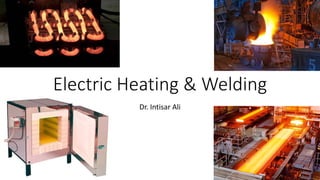
3. Introduction
Electric heating is a process in which Electrical Energy is converted into “HEAT
ENERGY”.
Domestic Applications:
• Room heater for heating the building
• Immersion heater for water heating
• Hot plates for cooking
• Geysers
• Electric kettles
• Electric Iron
• Electric oven for baking products
• Electric toasters
4. Industrial Applications
• Melting of metals
• Electric welding
• Molding of glass for making glass appliances
• Baking of insulator
• Molding of plastic components
• Heat treatment of different objects
• Making of plywood.
5. Advantages of Electric Heating
• Clean and atmosphere / Free from dirt.
• No pollution / No flue gas is produced
• Response quickly
• Accurate Controlled temperature can made easily
• Comparatively safe
• Localized application
• Overall efficiency is much higher
• Uniform heating
• Highest efficiency of utilization
• Cheap furnaces
• Mobility of job
7. 1. Heat Transfer by Conduction
• The heat transferred depends on the difference between the temperature of the
two points
• The heat transfer by conduction takes place in solids, liquids and gases
• In solids, heat is transferred from one molecule to adjacent molecule and so on
• There is no actual motion of molecules.
• Heat passed through a cubic body:
𝑄 =
𝑘𝐴
𝑡
𝑇1 − 𝑇2 𝑇
𝑡 =thickness, 𝑇1, 𝑇2= temperature of two faces, 𝑇=time duration in hours
K= Coefficient of thermal conductivity of material, 𝐴=Cross-section area
8. 2. Heat Transfer by Convection
• The heat transfer takes place from one part to another part of the
substance/fluid due to the actual motion of the molecules.
Example:
Immersion water heater
• Heat dissipation is given by the following expression:
𝐻 = 𝑎(𝑇1 − 𝑇2) 𝑏 𝑊/𝑚2
𝑎, b = constants depend upon the heating surface
9. 3. Heat Transfer by Radiation
• The heat transfers from the source to the substance without heating
the medium in between.
Example:
Solar heaters
• Stephan’s Law
𝐻 = 5.72 × 10⁴ 𝑘 × 𝑒 ×
𝑇1
1000
4
−
𝑇2
1000
4
𝑊/𝑚2
𝑒 = emissivity, 𝑘 = radiant efficiency
10. Requirement
of a Good
Heating
Element
• High specific resistance
• High melting point
• Low temperature coefficient of
resistance
• Free from oxidation
• High mechanical strength
• Non-corrosive
• Economical
11. Metals for the Heating Element
Sr.
NO
TYPE OF
ALLOY
COMPOSITION COMMERCIAL
NAME
SPECIFIC RESISTANCE
AT 200C
SPECIFIC
GRAVITY
MAXIMUM
TEMPERATURE
Nickel-
chromium
Nickel-
chromium Iron
Iron chromium
Aluminum
Nickel- Copper
80% Ni
20% Cr.
60% Ni
16% Cr.
24% Fe
65-75% Fe
20-30% Cr.
5% Al.
45% Ni
55% Cr.
Nichrome
Kanthal
Eureka
1.03 μΩ-m
1.06 μΩ-m
1.4 μΩ-m
0.49 μΩ-m
8.35
8.27
7.2
8.88
11500C
9500C
1150 to
13500C
4000C
1
2
3
4
-
12. Causes of Failure of Heating Element
• Formation of hot spot
• Element oxidation and intermittency of operation
• Embrittlement
• Contamination and Corrosion
16. Resistance Heating
• When current passes through a resistance ,Power loss takes place
there in ,which appears in the form of heat.
• Electrical energy converted into heat energy
𝐻 = 𝐼2 𝑅𝑡
• The loss of energy takes place only in transferring heat from element
to charge or load.
• Types:
• Direct resistance heating
• Indirect resistance heating
• Infrared/radiant heating
17. DIRECT HEATING
• Electric current is
passed through the
body (charge) to be
heated.
• High efficiency
• Mode of heat transfer
is Conduction
• Example-
1) Electrode boiler for
heating water
2)Resistance Welding
INDIRECT HEATING
• Electric current is passed through
highly resistive material(heating
element) placed inside an oven.
• Heat produced due to I²R loss in
the element is transmitted to the
body
• Mode of heat transfer is Conduction
&/or Convection &/or Radiation
• Example-
1) Room Heaters
2) Domestic & commercial cooking
3) Heat treatment of metals
23. Infrared/ Radiant Heating
• Heat transfer by radiation.
• Tungsten filament lamps are used with reflecting mirrors.
24. Temperature Control of Resistance Heating
• In resistance heating supply voltage and resistance of heating
elements are independent parameters
• Current is a dependent parameter
• The temperature of resistance furnace is controlled by
1. Supply voltage
2. By varying the number of heating elements
3. Switching ON and OFF the supply
25. Temperature control of resistance heating
Periodically switching
on & off of the power
supply
By varying supply
voltage
By varying
resistance
By variable
supply
By Auto-T/F
or Induction
regulator
By series
impedance
Final temperature α Time interval the switch remains ON
Total time interval of the ON/OFF cycle.
28. • When the same elements are changed from delta to star, the power
consumption reduced to one - third
29. Electric Arc Heating
• The electric supply given to two electrodes is increased and are
separated in air from each other.
• The air gets ionized at high voltage gradient and becomes a good
conductor of electricity.
• Current passes through the air gap in the form of arc.
• Once the arc is produced, small voltage is sufficient to maintain it.
• The electrodes are made of either carbon or graphite.
• The temperature of the Arc developed will be around 3500⁰C
30. Types of Arc Heating
• Direct arc heating
• Indirect arc heating
Two electrode arc furnace
FIG.1
SUPPLY
ELECTRODES
ARC
CHARGE
FURNACE
31. Advantages and Applications
Advantages
• High temperatures can be produced
• More uniform heating of the charge can be obtained
Applications
• The most common application of direct arc furnace is to produce steel
• Used in Research and Development.
• It is used in pilot production plants.
32. Indirect Arc Heating
• Heat developed in the charge
is by the radiation.
• The temperature of the charge
is lower than direct Arc furnace
• Current does not flow through
charge. Hence no inherent
stirring action.
• So, the furnace must be rocked
vibrating or tilting by
mechanically.
• Rocking action is operated by
an Electric motor.
33. Applications
• Indirect arc furnace is used for melting of non-ferrous metals.
• It can be used in iron foundries where small quantities of iron is required
frequently
• It is more suitable when the charge is to be varied frequently or heating is
intermittent
Advantages:
• Highly flexible
• High melting temperatures
• More economical
• Higher efficiency
34. Power Supply and Control for Arc Heating
• The power supply for the electric arc furnace is of low voltage and high
current type, due to:
• To achieve high temperatures, high currents are required.
• The max. sec. voltages are limited to few hundred of volts due to safety and
insulation considerations.
• Condition for maximum power output?
𝑅 𝐴 = (𝑅 𝑇 + 𝑅 𝐿)2+(𝑋 𝑇 + 𝑋 𝐿)2
• Power factor at max. power loss?
𝑃𝐹 =
1
2
1 +
𝑅 𝑇 + 𝑅 𝐿
𝑅 𝐴
≈ 0.707
36. High Frequency Heating
• Heating on the conducting materials (Ferro-magnetic and non-Ferro-
magnetic) – Induction Heating
• Heating of insulation materials – Dielectric Heating
• The heat transfer by high frequency heating is of higher order, i.e., 10
kW/sq.-cm
• Whereas the conventional methods produce only up to 20 W/sq.-cm.
37. Eddy Current Loss
• 𝐵 = 𝑃𝑒𝑎𝑘 𝑀𝑎𝑔𝑛𝑒𝑡𝑖𝑐 𝐹𝑖𝑒𝑙𝑑
• 𝑑 = 𝑆ℎ𝑒𝑒𝑡 𝑡ℎ𝑖𝑐𝑘𝑛𝑒𝑠𝑠 𝑜𝑟 𝑑𝑖𝑎𝑚𝑒𝑡𝑒𝑟 𝑜𝑓 𝑤𝑖𝑟𝑒
• 𝑓 = 𝑓𝑟𝑒𝑞𝑢𝑒𝑛𝑐𝑦
• 𝑘 = constant equal to 1 for a thin sheet and 2 for a thin wire
• 𝜌 = 𝑟𝑒𝑠𝑖𝑠𝑡𝑖𝑣𝑖𝑡𝑦 𝑜𝑓 𝑡ℎ𝑒 𝑚𝑎𝑡𝑒𝑟𝑖𝑎𝑙
• 𝐷 = 𝐷𝑒𝑛𝑠𝑖𝑡𝑦 𝑜𝑓 𝑡ℎ𝑒 𝑚𝑎𝑡𝑒𝑟𝑖𝑎𝑙
𝑃𝑙𝑜𝑠𝑠 =
𝜋2
𝐵 𝑚
2
𝑑2
𝑓2
6𝑘𝜌𝐷
39. Factors effecting heat developed in a disc
1. Primary coil current and its no. of turns
2. Supply frequency
3. Magnetic coupling between coil and disc
4. The electric resistivity of the disc
• For non-magnetic materials, the heat developed is due to eddy
current loss.
• For magnetic materials, the heat developed is both due to the eddy
current loss and hysteresis loss.
40. Hysteresis Loss
𝑃ℎ𝑦𝑠𝑡𝑒𝑟𝑒𝑠𝑖𝑠 = 𝐾ℎ × 𝑓 × 𝐵 𝑚
1.6
• At higher frequencies, the hysteresis loss is very small as compared to
the eddy current loss.
41. Induction Heating
• Alternating Current flows in a conductor produces alternating flux.
• If any other conducting material is placed in this magnetic flux emf gets
induced in it.
• This induced emf drives eddy current in that piece and power loss due to
eddy current appears as heat.
• it is proportional to relative permeability.
• Heating produced in magnetic material is more than non magnetic
material.
• Heating is proportional to MMF. Force can be varied by changing current or
number of turns.
• Heating effect can be increased by employing high frequency supply.
42.
43. Core Type Furnaces
• Currents are induced in the charge itself. This is usually used in
furnaces for smelting (extraction of metal from ore), melting of
metals etc.
• They are classified as core and coreless type induction furnaces.
44. (a) Direct Core Type
• Weak magnetic coupling between
primary and secondary High
leakage reactance.
• At normal frequency, there is a severe
turbulence and stirring action.
• So the furnace is operated at low
frequency of order 10 HZ.
• Pinch effect due to normal frequency
and high current densities.
• Frequency changer/motor generator
sets are used to achieve low frequency
supply.
• To start the furnace molten metal is
required in the hearth.
45. (a) Direct Core Type – Vertical core furnace
• Improvement over the direct core type
furnace.
• Also known as Ajax-Wyatt Induction
furnace.
• Avoid pinch effect
• Higher magnetic coupling
• Higher power factor
• Lower level of pinch effect due to weight of
charge.
47. (c) Indirect Core Type Furnace
• Used to provide heat treatment to
metals.
• Secondary winding itself forms the
walls of the container.
• The magnetic circuit losses its mag.
Properties at certain temperature.
• At critical temperature, the
reluctance of mag. circuit increases
and inductive effect decreases,
thereby cutting off heat supply.
48. Coreless Type Induction Furnace
• The container may be conducting
or non-conducting.
• If container is made up of
conducting material, charge can
be conducting or non-conducting.
• If the container is of non-
conducting material then charge
should have conducting
properties.
• Flux densities are low as there is
no core so high frequency is
required to compensate low flux.
49. Advantages of coreless furnaces
• Ease of Control
• Oxidation is reduced
• Automatic stirring
• Less cost
• Any shape of crucible can be used
• Suitable for intermittent operation.
50. Dielectric Heating
𝑃𝐿𝑜𝑠𝑠 = 𝑉𝐼 cos ∅ = 𝑉𝐼 𝑅 = 𝑉𝐼 𝐶 tan 𝛿 = 𝑉 ×
𝑉
𝑋 𝐶
tan 𝛿 = 𝑉2
𝜔𝐶 tan 𝛿 = 𝑉2
𝜔
𝜀 𝑜 𝜀 𝑟 𝐴
𝑑
tan 𝛿
𝑃𝐿𝑜𝑠𝑠 ∝ 𝑉2
and 𝑃𝐿𝑜𝑠𝑠 ∝ f
51. Advantages & Applications
• Heating of non-conducting materials
• Uniform heating is possible
• Heat is produced in the whole mass
Applications:
• Drying of papers, Gluing of wood, Sealing of plastic sheets,
Dehydration heating in the dairy industry, etc.
54. Introduction
• Definition: The process of joining two pieces of metal or non-metal
together by heating them to their melting point.
• Filler metals may or may not be used in joining process.
• Physical and mechanical properties of the metals/nonmetals to be
welded are of much importance (melting point, thermal conductivity,
tensile strength, etc.)
• Types:
• Thermal welding, Gas welding, Electric welding
56. Resistance Welding
• Process of joining two metals
together by the heat produced
due to the resistance offered to
the flow of electric current at the
junction of two metals.
• Resistance to the flow of current is
made up of:
1. Resistance of current path in the
work piece.
2. Resistance between the contact
surfaces of the metals
3. Resistance between the
electrodes and the surface of
parts being welded.
57. Resistance Welding …
• The resistance welding processes differ from many of the other more
popular welding processes.
• Filler metal is rarely used.
• The welding depends upon the following factors:
1. The amount of current that passes through the work
2. The pressure that the electrodes transfer to the work
3. The time the current flows through the work.
58. 1. Spot Welding
• High current at a low voltage flows
through the circuit and is in accordance
with Ohm’s law.
• Welding current varies between 1000 to
10000 A.
• Voltage between electrodes is less than
2V.
• The current flows across the electrodes
and metal, causing the formation of the
weld nugget.
• When the welding current is turned off,
the weld cools causing the welding
nugget to becoming solid while joining
the two pieces of metal.
https://youtu.be/AwL1CAg43PU
59. 2. Seam Welding
• Series of continuous spot welding.
• The welding electrodes are motor-driven
wheels.
• Used for leak proof joint formations.
https://youtu.be/YhWpub7NDss
https://youtu.be/bg_fDRr7tUc
61. 4. Butt Welding – Upset Butt
• Instead of electrodes the metal
parts that are to be joined
(butted) are directly connected to
the supply.
• Types:
• Upset butt welding
• Flash butt welding
• Percussion butt welding
• In Upset butt welding, the metals
parts are joined end to end.
• Used for welding of rods, pipes,
wires etc.
https://youtu.be/MMzk5blgtbM
63. 4. Butt Welding – Percussion
• Self timing soft welding method
based on flash butt welding
mechanism.
• Used for the welding of dissimilar
metals
64. Choice of Welding Time
Dimensions of material Optimum time
2 X 24 SWG 8 cycles
2 X 14 SWG 20 cycles
2 ¼” 2 sec.
65. Electric Arc Welding
• It has negative resistance characteristics.
• Types:
• Carbon Arc welding
• Metal Arc welding
• Atomic Hydrogen Arc welding
• Inert gas metal arc welding
• Submerged arc welding
66. Electron – Beam Welding
• Heat required for the welding operation is obtained by electron
bombardment heating.
𝑃 = 𝑛 × 𝑞 × 𝑣
𝑛= no. of charges particles
𝑞= charge on Coulombs/m
𝑣= voltage required for acceleration