
Recommended
Recommended
More Related Content
What's hot
What's hot (14)
Viewers also liked
Viewers also liked (10)
Similar to Autonomous Library Book Robot
Similar to Autonomous Library Book Robot (20)
Recently uploaded
Recently uploaded (20)
Autonomous Library Book Robot
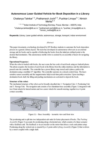
- 1. Autonomous Laser Guided Vehicle for Book Deposition in a Library Chaitanya Talnikar1, a , Prathamesh Joshi2, b , Pushkar Limaye3, c , Nimish Mehta4, d 1, 2, 3, 4 Indian Institute of Technology Bombay, Powai, Mumbai – 400076, India a chaitanya.talnikar@iitb.ac.in, b prathamesh.joshi@iitb.ac.in, c pushkar_limaye@iitb.ac.in, d nimish_mehta@iitb.ac.in Keywords: Library, Laser guided vehicle, autonomous, storage, transport, indoor environment Abstract This paper documents a technology developed by IIT Bombay students to automate the book deposition process in a generic Library layout. The team has developed an autonomous robot acts as an external storage unit for books and is capable of delivering the books from the initial pre-defined point to the desired final destination. This autonomous mobile robot is assisted by an assembly of lasers for navigating the library. Operational Sequence: When the robot is loaded with books, the user scans the bar-code of each book using an Android phone. The phone acquires the location of each book in the library from the online database and the information is passed onto the controller. The controller has a preset library map stored and it plans a path to the destination using a modified A* algorithm. The controller operates in a closed-control loop. The laser- sensitive sensor-assembly and the magnetometer help in real-time path correction. Upon reaching a destination book shelf, the lifting and pushing mechanisms are activated to deposit the book. Structure of the robot: The mechanical structure of the robot can be broadly classified into 1. Navigation Unit, 2. Positioning Unit and 3. Storage Unit. The navigation unit consists of an Aluminium base assembly (Figure 1) integrated with two Omni wheels for lateral motion and two castor wheels for smooth steering, together in a 4-point contact assembly. Figure (1) – Base Assembly – isometric view and front view The positioning unit is split into two independent sub-units for better placement of books. The Pushing Assembly (Figure 3) accounts for positioning along a horizontal axis; which consists of a linear actuator with a feedback unit. The feedback is via an encoder on the motor that drives a rack-and-pinion setup. Positioning along the vertical axis is ensured by a 2-point cable Lifting Assembly (Figure 2) that is driven by a motor coupled with a single shaft.
- 2. Figure (2) – Lifting Assembly Figure (3) – Pushing Assembly Navigation and Path Finding Algorithm: For the navigation of the bot the A* algorithm is used with a few modifications. The algorithm computes the path given a map and the initial position and final position. The bot is assumed to be a point (situated at the centre of mass of the bot) while computing the path using the A* algorithm. The complete algorithm is divided into 3 parts: Pre-processing, A* and Post-processing. Pre-processing: As the bot is assumed to be a point, we need to ensure that in the path computed using A*, the bot doesn't hit any obstacles. A certain minimum distance needs to be maintained between the obstacle and the centre of mass of the bot. This can be ensured by modified the map, applying padding around the obstacles. So on the map a circle is drawn around every pixel which is on the boundary of an obstacle, increasing the effective size of the obstacle. The A* algorithm is then applied using the map generated in pre-processing. A*: The A* algorithm is a heuristic path finding algorithm. In this algorithm the map is divided into cells which are equivalent to pixels in this case. Each cell that the bot visits/can visit is attributed with a cost function which is a sum of the distance travelled until now and the least distance to the destination. From the initial position, the bot first checks the surrounding cells and calculates the cost function for each of them, a list of the costs of the traversed cells is maintained. The cell which has the least cost is chosen next and same process is again applied and repeated till the bot reaches the destination. A Binary heap has been used to implement the list to ensure that the least cost cell always remains on the top. Post-processing: The path generated using the A* algorithm is one of the paths, it isn't the shortest path. This path also consists of a lot of turns. So there is a need to calculate a shorter path which doesn't take so many turns. In Post-processing two points on the A* path are taken and if they are directly connected without any obstacles in between then the straight line path between the two points is taken instead of the A* path. To check whether obstacles lie on the straight line path, a thick line is drawn between the two points using the Bresenham algorithm. The width of the line is same as that of the bot. If any obstacle coincides with the line then the straight line path is rejected. To generate a shorter path using the above method, the initial points taken are the initial and final positions, if they are directly connected then the straight line path is chosen and the starting point is set to the ending point, else the end point is shifted to final position – 1 and the process is repeated. Laser Navigation: The robot navigates the library with the help of a grid of lasers designed for the location. The grid is generated with the help of standard laser transmitter modules each of which contains a laser-diode and a timing circuitry that modulates the laser to an adjustable frequency. Arrays of Light Dependent Resistors (LDRs) are precisely mounted on the robot at the same height as the laser grid (typically 10 cm from
- 3. ground) to get information from the laser-grid. The LDR output is fed to a simple tone-decoder circuit implemented using IC567 to selectively filter out the transmitter frequency. This ensures immunity to ambient frequencies and hence prevents false detections. Laser navigation was chosen over other possibilities (GPS, IMU etc) due to the systems reliability at low costs and flexible degree of accuracy. The number and placement of laser- transmitters is governed by the response of the system bot in the absence of feedback. This allows us to identify the distance after which the robot significantly deviates from the pre-assigned path and we set up a laser- transmitter at that distance to apply the correction. Denser laser-grid results in a more faithful path-following. Besides the laser-navigation system, an on-board magnetometer helps the robot in navigation. The magnetometer used here HMC6352 digital compass, has the resolution to the tenth of a degree and gives the orientation of the robot relative to the magnetic North with sufficient accuracy. Controller: The robot is controlled by an ATMega2560 microcontroller board which handles the on-board sensors and actuators. The LDR arrays mounted in 4 directions and the magnetometer output their digital values directly to the controller. The controller executes the navigation process in a timed loop and requests data from these devices. An Android phone (also on-board) is used to scan the bar-code of a book to identify the location of the book in the library by wirelessly connecting to the library database. The controller communicates with the Android device as a USB host via a USB Host-shield on top and gets the coordinates of its target location(s) before navigating through the library. The controller also outputs data to motor drivers that drive the Omni-wheels and the lifting and pushing assemblies. Feedback from Omni-wheels is obtained through position encoders on the wheels; while that from the lifting assembly is gathered via distance sensors. Brief overview of the system with the controller is illustrated in Figure (4). Arrows indicate direction of data-flow Figure (4) – System block diagram The robot is designed to work well with library layouts like that of the IITB Central Library.
- 4. Figure (5) - Plan View of a section of the Library with laser-grid Besides a laser-grid that has to be uniquely designed for every library locale, the robot needs a database to know the location of each book in the library and a system for unique identification (bar-code preferably) of each book. Possible Extensions: The flexibility of the system allows us to adapt this technology to a variety of locales by generating the appropriate laser-grid for navigation. With slight modifications in design this system can be ported for use in areas that require fast and efficient storage and retrieval of components as in a manufacturing shop-floor or a super-market counter. References: 1. A* Algorithm: http://www.policyalmanac.org/games/aStarTutorial.htm 2. Path finding: http://www.gamasutra.com/view/feature/3096/toward_more_realistic_pathfinding.php 3. Tone Decoder: http://www.ti.com/product/lm567c&lpos=Middle_Container&lid=Alternative_Devices#technicaldocument s 4. Digital Compass/ Magnetometer: http://www51.honeywell.com/aero/common/documents/myaerospacecatalog-documents/Missiles- Munitions/HMC6352.pdf