
Recommended
More Related Content
What's hot
What's hot (20)
Similar to Stack and subroutine
Similar to Stack and subroutine (20)
Recently uploaded
Recently uploaded (20)
Stack and subroutine
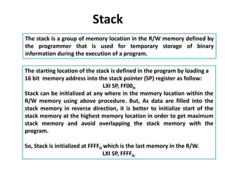
- 1. Stack The stack is a group of memory location in the R/W memory defined by the programmer that is used for temporary storage of binary information during the execution of a program. The starting location of the stack is defined in the program by loading a 16 bit memory address into the stack pointer (SP) register as follow: LXI SP, FF00H Stack can be initialized at any where in the memory location within the R/W memory using above procedure. But, As data are filled into the stack memory in reverse direction, it is better to initialize start of the stack memory at the highest memory location in order to get maximum stack memory and avoid overlapping the stack memory with the program. So, Stack is initialized at FFFFH which is the last memory in the R/W. LXI SP, FFFFH.
- 2. One stack is initialized in the R/W memory, storing data into the stack, start from previous memory location of the initialization value. That is if stack is initialized as LXI SP, FFFF So first data is stored into FFFE location, next data is stored in FFFD location and so on in reverse order. 11 22 33 44 55 66 77 R/W memory FFF9 FFFA FFFB FFFC FFFD FFFE FFFFSP LXI SP, FFFF
- 3. Storing data into stack memory The 8085 microprocessor has two instructions PUSH and POP for storing data into stack memory and retrieving it back respectively in LIFO. Both instruction works with register pair only. PUSH: It is used to store the content of register pair onto the stack memory in reverse order (decreasing memory address) POP: It is used to transfer data bytes from stack memory into the respective register pair. PUSH Instruction POP Instruction Operation with PUSH B POP B B – C Register pair PUSH D POP D D – E Register pair PUSH H POP H H – L Register pair PUSH PSW POP PSW Accumulator and Flag
- 4. PUSH B Decrement SP by 1 Copy the contents of register B to the memory location pointed by SP Decrement SP by 1 Copy the contents of register C to the memory location pointed by SP So, SP is decremented by two. LXI SP,FFFF PUSH B 11 22 R/W memory FFF9 FFFA FFFB FFFC FFFD FFFE FFFFSP LXI SP, FFFF A F B 11 C 22 D E H L SP
- 5. PUSH D Decrement SP by 1 Copy the contents of register D to the memory location pointed by SP Decrement SP by 1 Copy the contents of register E to the memory location pointed by SP So, SP is decremented by two. LXI SP,FFFF PUSH B PUSH D PUSH PSW 11 (B) 22 (C) 33 (D) 44 (E) A F R/W memory FFF9 FFFA FFFB FFFC FFFD FFFE FFFFSP LXI SP, FFFF A F B 11 C 22 D 33 E 44 H L SP
- 6. POP H ▪ Copy the contents of the memory location pointed to by the SP to register L. ▪ Increment SP by 1 ▪ Copy the contents of the memory location pointed to by the SP to register H ▪ Increment SP by 1 ▪ SP is total incremented by two. LXI SP, FFFF PUSH B POP H A F B 11 C 22 D E H 11 L 22 11 (B) 22 (C) R/W memory FFF9 FFFA FFFB FFFC FFFD FFFE FFFFSP LXI SP, FFFF
- 7. Conclusion: During pushing, the stack operates in a “decrement then store” style. The stack pointer is decremented first, then the information is placed on the stack. During poping, the stack operates in a “use then increment” style. The information is retrieved from the top of the stack and then the pointer is incremented. The SP pointer always points to “the top of the stack’’.
- 8. Subroutine A subroutine is group of instruction written separately from the main program to perform a function that occurs repeatedly in the main program When a main program calls a subroutine the pro gram execution is transferred to the subroutine. After the completion of the subroutine ,the program execution returns to the main program. So, The microprocessor uses the stack to store the return address of the subroutine.
- 9. The 8085 has two instructions for dealing with subroutines. o The CALL instruction is used in the main program to redirect program execution to the subroutine. o The RET instruction is used at the last of the subroutine to return the execution to the calling routine. When a subroutine is called, address of the next instruction following to the call instruction is PUSHed into the stack automatically and program execution is transferred to the subroutine address. When RET instruction is executed at the end of the subroutine, the returned address which was stored into the stack memory during CALL, is retrieved into PC and execution is resumed in the main program. CALL instruction must be used in conjunction with the RET instruction in the subroutine. During Subroutine Stack must be initialized.
- 10. CALL 4000H o 3-byte instruction. o Push the address of the instruction immediately following the CALL onto the stack and decrement the stack pointer register by two. o Load the program counter with the 16-bit address supplied with the CALL instruction. o Jump Unconditionally to memory location.
- 11. RET o 1-byte instruction o Retrieve the return address from the top of the stack and increments stack pointer register by two. o Load the program counter with the return address. o Unconditionally returns from a subroutine. RET
- 12. Main Program 8000: LXI SP,FFFF 8020: CALL 9000 (opcode of CALL) 8021: lower byte operand (00) 8022: Higher byte operand (90) 8023: Next instruction following to the call 802F: RST 1 Subroutine 9000: First subroutine Inst. 900F: RET CALL and RET Sequence
- 13. Call instruction sequence: Call is a three byte instruction. So, depending upon the byte size of the instruction it has opcode fetch, Memory read and memory read. Again, before jumping to the subroutine, return address (i.e. content of PC value which is the address of next instruction following to the call is to be stored onto the stack memory). So, along with the above three M/C, it has also mem. Write ( storing higher address onto stack) and mem. Write ( storing lower address onto the stack) M/C. CALL 9000 8020: opcode of call (OF) 8021: 00 (MR) 8022: 90 (MR) PC 8023: Next Instruction Value of PC is the return address after completing the subroutine. So, PC value is to be stored into the stack memory before going to the subroutine using automatic PUSH operation.
- 14. M/C SP FFFF Add. Bus AB PC PCH PCL Data Bus DB Int. Reg. W Z M1 OF FFFE SP-1 8020 8021 Opcode CD --------- M2 MR FFFE 8021 8022 00 --- 00 M3 MR FFFE 8022 8023 90 90 00 M4 MW FFFD SP-2 FFFE 8023 80 PCH 90 00 M5 MW FFFD FFFD 8023 23 PCL 90 00 OF Of 1st inst. In Subroutine FFFD 9000 9001 90 00 Mem Add. Code 8020 CD 8021 00 8022 90 8023 Opcode of next PC 23 80 ---------- FFFD FFFE FFFF Stack
- 15. RET instruction sequence: RET is a 1-byte instruction. So, depending upon the byte size, it has only OF M/C. But when RET instruction is executed, program sequence is transferred to the main program by POPing the return address to PC from stack memory which was saved during call. Then, execution resume from this address. So, Two extra memory read is required to get return address. M/C of RET are OF, MR (reading lower value of return address from stack), MR (reading higher value of return address from stack) 900F: RET instruction opcode (OF) PC 9010:
- 16. M/C SP FFFD AB PC PCH PCL DB W Z M1 OF FFFD 900F 9010 C9 ----------- M2 MR FFFE SP+1 FFFD 9010 23 From top of stack ---- 23 M3 FFFF Sp+2 FFFE 9010 80 80 23 M1 OF of inst. Next to CALL FFFF 8023 8024 opcode 80 23 900F C9 FFFD 23 FFFE 80 FFFF ------- Stack SP
- 17. Restart and Conditional CALL and Return Instruction: In addition to the unconditional call and return instruction , the 8085 instruction set has eight restart instruction and eight conditional call and return instruction. Restart (RST) instruction: RST instruction are 1-byte call instruction that transfer the program Sequence to a specific location on ooH memory page. They are executed the same way as CALL instruction. When RST instruction is executed, the 8085 stores the content of the PC (i.e. address of the next instruction) on the top of the stack and transfers the program sequence to the fixed restart location. These instructions are generally used in conjunction with the interrupt process. RST 0 CALL 0000 RST 1 CALL 0008 RST 2 CALL 0010 RST 3 CALL 0018 RST 4 CALL 0020 RST 5 CALL 0028 RST 6 CALL 0030 RST 7 CALL 0038
- 18. Conditional CALL and RET instruction: Conditional call and return instruction are based on the four conditional flag bits: CY, P, Z, S. In case of conditional CALL, program is transferred to the subroutine if the condition is met, otherwise main program execution continue. In case of conditional RET, the sequence returns to the main program if the condition is met, otherwise execution in the subroutine continued. Last instruction of any subroutine must be unconditional RET otherwise sequence can’t return to the main program if condition not met. Unconditional CALL: Unconditional RET: CC Call subroutine if CY=1 RC Return from subroutine if CY=1 CNC Call subroutine if CY=0 RNC Return from subroutine if CY=0 CZ Call subroutine if Z=1 RZ Return from subroutine if Z=1 CNZ Call subroutine if Z=0 RNZ Return from subroutine if Z=0 CM Call subroutine if S=1 RM Return from subroutine if S=1 CP Call subroutine if S=0 RP Return from subroutine if S=0 CPE Call subroutine if P=1 RPE Return from subroutine if P=1 CPO Call subroutine if P=0 RPO Return from subroutine if P=0
- 19. Multiple Calling and Nesting of a subroutine
- 20. Multiple Ending of a subroutine