SlideShare a Scribd company logo
1 of 17
Download to read offline
Installation Instructions
Pluto Range Gas Ducted Heater
(For internal installation only)
(P12, P20, P25)
Eco Pacific Pty. Ltd.
ABN 94 117 653 924
23 Marni Street
Dandenong, Victoria 3175
Telephone: (03) 9706 6226
Fax: (03) 9706 6089
Web: www.ecopacific.com.au
2
Eco Pacific Pluto Range Gas Ducted Heaters
(Installation Instructions)
CONTENTS Page
Description of the heater 3
General requirements 4
Installation (internal) 5
Pre-commissioning check list 9
Operating instructions 9
Commissioning procedure 11
Final Checks 12
Figures:
Figure 1&2: General aspects 3
Figure 3: Required clearances 5
Figure 4: Gas valve connections 7
Figure 5: Power point connection polarity 7
Figure 6: Dimension locations 14
Figure 7: Wiring Diagram 14
Pluto dimensions and specifications
Table 1: Specifications data 13
Table 2: Pluto Dimensions 13
Important Notice to Agents, Installers and Purchasers
Although Eco Pacific endeavours to provide appliances of a high standard, it is
important that you be aware that problems can occur if the equipment is not
properly installed. There are standards covering installation, which has been
stipulated by the Australian Gas Association, and the guidelines for installation
as written in this booklet are in accordance with those standards. If an
appropriately qualified person is not used to install the equipment or if the
equipment is not installed according to the guidelines provided, then Eco Pacific
will not be able to accept responsibility for any problems, which occur as a result.
Abbreviations
Abbreviation Quantity Units
A Amperage Amperes
Ph Phases
V Voltage Volts
kW Heating Capacity kiloWatts
MJ Energy MegaJoules
h Time Hours
Hz Frequency Hertz
3
Description
The Pluto class of heaters is a single packaged central heating unit. Throughout
these installation instructions reference is made to the aspects of the heater
given in Figures 1& 2.
Figure 1: General aspects
Figure 2: Different elevations
As shown in figure 2, the rear side of the unit is considered to be the end, which
contains the supply air duct connection. Using the rear panel as an initial
reference the front panel contains access to the Printed Circuit Board (PCB)
controls, the gas burner and the gas valve. The gas connection is made towards
the front on the lower section of the left hand side panel. Access to the fan wheel
and motor is achieved on the right hand side.
4
General Requirements
The installation of this appliance must conform to the following requirements:
1. These installation instructions.
2. The Australian Gas Association Code, AG 601.
3. Local gas fitting regulations.
4. Local building regulations.
5. Local electrical supply authority regulations.
Models
These installation instructions cover the Eco Pacific Pluto range of internal
heaters. This range of heaters is intended for use with natural gas or LPG.
Performance
Information on the performance and overall dimensions of each model may be
found in Table 1 and Table 2 respectively. The appliance data plate found on
the front panel of each heater unit complements this information.
Important Notes
AUTHORIZED PERSONNEL must install this appliance and must carry out
likewise servicing of this unit.
Inspection
As soon as a unit is received it should be inspected for any damage that may
have occurred during transit. If any damage is evident it should be noted on the
carrier’s freight bill.
Location
The Pluto is an internal air heater, designed for installation in either a roof space
or underneath a floor space, and for connection to a ducted warm air heating
system. Refer to Table 2 for general dimensions. Although the location is
usually predetermined please check with the owner’s or dealer’s installation
plans. If a location has not been decided on, consideration must be given to the
following:
1. The location must provide adequate structural support; space for service
access; and clearances for return and supply air duct connections.
2. Care should be taken to locate the unit and ductwork so that the supply air
does not short circuit to the return air.
3. Proper electrical supply must be available.
4. Proper gas supply must be available.
5. Clearances, as outlined in the next sub-section, must be provided.
5
Clearances
For servicing, a minimum clearance of 300 mm must be provided on all sides of
the appliance, with 600 mm required at the front of the unit, as shown in Figure
3. A 300 mm wide walkway must be provided for servicing, in accordance with
AG 601, Gas Installation Code.
NOTE: Ducting must not intrude on these clearances for servicing, except for
connections.
Figure 3: Required clearances
Installation
Procedure
The following sequence of installation steps is suggested. Reference is also
made to the Final Checklist.
1. Inspect the unit and set in position.
2. Make electrical power connections.
3. Route the gas piping and connect to the unit.
4. Connect all ductwork.
5. Connect the flue.
6. Make electrical control connections.
7. Power up the heating unit.
8. Start and check the system for correct operation.
9. Instruct the owner on operation of the unit and advise on any servicing and
maintenance aspects.
6
A) Roof Space Installation
1. The area in the roof space must be capable of supporting the additional load
of the appliance.
2. Access must be available to the appliance, by means of fixed access, a
normal ladder or steps.
3. A walkway must be provided between the access point to the roof space and
the appliance. This walkway must be permanently fixed, capable of carrying
the weight of a person, and extend all the way around the appliance.
4. Permanent lighting must be provided at the appliance, with the switch
located at the point of entry to the roof space.
5. The unit must be installed on a solid base (fire retardant board exempt),
extending 300mm in front of the unit. A minimum clearance of 200 mm
between the top of the appliance and any combustible material must be
maintained.
6. Ensure that any ceiling insulation material is kept clear of the appliance by a
minimum of 300 mm.
B) Under Floor Installation
The Pluto may be installed under the floor, provided that:
1. A minimum clearance of 1200 mm exists between the underside of the floor
joists and ground level. This clearance is to extend from the access opening
to the appliance, and around the appliance.
2. Where minimum clearances exist as above, the appliance shall be located
within 2 m of the access opening.
3. Where greater clearances than above exist, the appliance may be installed at
any distance from the access opening.
4. A minimum clearance of 200 mm between the top of the appliance and the
lowest part of the floor structure must be maintained.
5. The appliance is to stand on a level concrete base of at least 50 mm
thickness, and provision must be made to drain away any seepage or ground
water so that water cannot come into contact with the appliance.
6. Fixed artificial lighting must be provided at the appliance, with the switch
located adjacent to the access opening.
Fluing
The appliance must be flued to the outside environment, in accordance with the
Gas Installation Code, AG 601. The size of the circular flue required for each
model Pluto is given in Table 2. Lateral flue runs shall not exceed half the total
flue run and have a minimum rise of 20 mm per metre run. If the location does
not permit this, provision shall be made for a duct to carry the flue vertically off
the appliance through the building to terminate in the ambient atmosphere.
Gas Piping
A licensed gas fitter must install the gas piping. The connection at the
appliance is to a ¾” BSP male thread, located at the inlet of the gas control
(found at the lower front left hand side of the unit). A single female ¾” BSP flare
nut is supplied with the unit for connection to the required gas piping. An AGA
approved appliance isolating cock must be installed close to the unit. Gas piping
7
material and size must be in accordance with the Gas Installation Code, AG 601.
The gas connection must be tested for any leakage. Do not use an open flame
or other source of ignition for leak testing. The following diagram illustrates a
typical gas valve showing the location of the gas inlet and outlet and the
pressure testing point.
Figure 4: Gas valve connections (Note: the valve used may differ slightly from that shown)
Electrical Requirements
Power Connections
Check that the electrical supply meets the values specified on the nameplate
and wiring diagram of the unit. The wiring diagram should be found on the front
panel of the heater. A 10-ampere general-purpose outlet is required to be
positioned within 1.5 m of the appliance. Wiring shall be in accordance with
the local supply authority regulations. Ensure that the polarity of the power
outlet is correct, as shown in Figure 5.
Figure 5: Power point connection polarity
A suitable artificial light is to be provided near the appliance to assist with
servicing and the switch placed adjacent to the access opening.
8
Room Thermostat
The appliance is supplied with either a manual or a programmable electronic
room thermostat. The thermostat should be installed on an internal wall,
approximately 1.5 m above the floor where it will be exposed to normal room air
circulation. It should not be installed on an outside wall or where it is exposed to
direct sunlight, heat sources, draughts, or other conditions, which could
adversely affect its operation. Generally, the living or dining room is a suitable
location, provided there are no cooking facilities or refrigeration appliances on
the opposite wall facing the thermostat. Mount the thermostat and route the 24-
volt control wiring from the thermostat to the heater unit. Connect the terminals
labelled “R” and “W” on the thermostat to the screw type terminals labelled “R”
and “W”, respectively, on the PCB connection strip. The heat anticipator setting
for the manual thermostat should be set at 0.6 Amps. Ensure that the hole
through the wall for wiring to the thermostat is sealed to prevent draughts from
affecting the thermostat. The control wiring that passes into the heater should
use the supplied cable gland. This gland should be fixed in the hole located at
the lower left hand side of the upper access door. For further information
concerning the thermostat please refer to the separate thermostat instructions
supplied with the unit.
Duct Connections
All return air duct connections are circular. On all models the supply air ducting
is elliptical. Refer to Table 2 for dimensions. A single starting collar is provided
with the unit. It is very important to the success of the installation that the
duct system be properly designed and installed.
Warm Air Ducting
From the outlet/supply air duct connection of the unit, install adequately sized
ductwork to the outlet/supply air registers. Flexible ducting should be used
where noise transfer may be a problem particularly at the duct connection points.
All ductwork, fittings and registers shall be sized to comply with AG 706, Design
Manual for Indirect Gas Fired Ducted Warm Air Central Heating Systems. It is
highly recommended that the ductwork be insulated, especially where it runs
through an unheated space. The supply air connection should be transitioned to
the proper duct size. All ducts should be suspended using flexible hangers.
Ductwork should not be fastened directly to the structure. Care should be taken
to ensure that all ducting is free of internal obstructions, free of leaks and
adequately supported. Likewise ducting should not be crushed or slack in any
manner.
Return Air Ducting
A return air duct must be provided and should draw air from a central location
within the house. The recommended duct length is 6 meters. This ducting may
be installed to either or both of the return air connections found on the left and
right hand rear sides of the unit. In instances where the unit is drawing air from a
building cavity make certain that it is fully sealed. This ensures that outside air is
not drawn into the system, which will affect unit performance.
9
Outlet Registers
Suitable outlet registers must be provided in all areas being heated.
Filters
The use of filters is recommended in order to keep the duct system clean and to
collect dust, lint and other debris from entering the heating unit. A filter is usually
installed in the return air duct. It should be in a position where it is accessible for
ease of cleaning. Where a filter is fitted, the return air grille dimensions should
be increased by at least 30%.
Add-On Cooling
Where, either presently or in future, add-on cooling is to be installed the indoor
coil section should be installed at least 3 metres downstream of the supply air
duct connection.
System Balancing
Provision for system balancing by using dampers or other suitable means for
adjusting airflows must be provided in the duct layout.
Fan Adjustment
The fan is preset at the factory to operate at high speed. The speed can be
changed by changing the wiring to different step points on the socket of the fan
scroll.
Notes
1. A minimum 30-second delay should be given to allow the fan to reach the
selected speed.
2. It is important that the fan speed be set so that discharge air temperature does
not exceed 60 ºC.
Pre-commissioning Check List
• Have all the gas lines been checked for leaks?
• Is the blower correctly wired?
• Thermostat correctly wired with correct polarity?
• Thermostat anticipator set to 0.6 Amps?
• Filters clean and in place?
• Outlet registers and return air grille are open?
• Ductwork sized adequately and correctly installed?
Operating Instructions
The Pluto heater does not have a standing pilot. It is equipped with an energy
saving electronic ignition device, which automatically lights the burner when the
10
thermostat calls for heat. Do not manually light burners with a match or other
source flame.
Preliminary
Set the wall thermostat to the “OFF” position.
Open duct registers in rooms.
Check gas supply is turned on at gas cock.
Lighting Instructions
Step 1. Check that the thermostat is set to “OFF”.
Step 2. Turn 240 VAC power “ON” at unit.
Step 3. Turn the thermostat to “ON” and to a temperature above ambient
room temperature. Unit should ignite in approximately 30 seconds.
Step 4. For natural gas and LPG units the heater will attempt ignition only
once and should ignite, however, attempts ignition again if the
flame is lost due to some reason. The PCB on the board rechecks
ignition every hour then after.
Sequence of Events
a. When the thermostat is turned up it calls for heat.
b. The appliance control enters a pre purge period of 30 seconds.
c. A direct spark ignitor will be energised to ignite the gas after the pre-purge
period.
d. Simultaneously the main gas valve opens.
e. The burner will light and the flame sensor will detect the presence of the
flame. The ignitor will de-energise after the flame is sensed. If the flame
sensor does not detect the presence of the burner flame, the gas valve
will close.
f. The room fan will come on after 30 seconds.
g. The furnace will remain in operation until the thermostat is satisfied.
h. Once the thermostat is satisfied, the gas valve will close and the fan will
turn off after approximately 50 seconds.
If the unit does not ignite-
Step 5. Turn the thermostat to “OFF” for 3 seconds, then back on again.
Step 6. Turn the thermostat to “ON”. Unit should ignite in approximately 30
seconds.
11
Often in new installations there is a period of time required to purge the gas line
of any air, which may be present. If having proceeded through steps 1-6 and
determined that the gas line has been purged of gas and the system still fails to
ignite/operate correctly, refer to the Service Instructions and wiring diagram given
in the end, or contact the Service Division of Eco Pacific on (03) 9706 6228.
Consideration should be given to the other possible causes for the equipment to
fail to operate. The PCB LED flashing at varying rates as listed below indicates
some of these other problems:
2 flash = system lock out- failed to detect or sustain flame. Check that the
flame sensor is connected on to the board and positioned
properly above the burner port.
4 flash = High limit or manual overheat switch opened, wait until the
auto switch closes, or if manual cut off- see if there is
obstruction in the duct, open more registers, manually reset the
manual switch and try the ignition from the thermostat again.
5 flash = Flame sensed and Gas valve not energised, check the gas
valve.
Steady light on = internal failure (microcontroller failure and power on self-
check)
If the system still fails to operate, please contact Eco Pacific on (03) 9706 6228.
Once the unit is operating, set the thermostat to the temperature which satisfies
your comfort requirements.
Commissioning Procedure
1. Check the burner pressure setting. The pressure test point is as shown in
Figure 4 and is a 3/8” gland type fitting. The correct pressure for Natural Gas
is 0.87 kPa. The correct pressure for LPG is 2.7 kPa.
2. Have the appliance ignite by setting the room thermostat to call for heat by
raising the set point above the current room temperature.
3. Having successfully achieved ignition, after a period of 5 minutes, check the
airflow at all the registers and adjust the dampers to achieve design air
quantities. Maximum air delivery temperature at the outlets should not
exceed an average of 50 ºC. Maximum air delivery temperature at the supply
air connection should not exceed 60 ºC, or 55 ºC for Extra Air models. If this
requirement is not met the blower speed must be increased.
4. Check the operation of the over temperature switch by restricting the airflow
(the over temperature switch will automatically reset on cooling down).
Restricting the airflow can be achieved by blocking the area of the return air
grille.
5. Turn the room thermostat to “OFF”. The fan should stop after a period of
approximately 50 seconds.
6. Check the flue for leaks and spillage. Spillage may occur if the flue
installation is faulty. If so this situation must be corrected.
12
The user must be instructed on how to correctly operate the system
All units are fitted with automatically resetting high temperature limit switches. It
is important to leave a minimum number of registers open otherwise the unit will
cut out on the high temperature limit (a typical number is approximately 3, 6 & 8
for P12, P20, & P25 respectively).
In the case of power failure, the unit will go to lockout and the high temperature
limit switch may be activated. When power is restored the high temperature limit
will automatically reset but the thermostat will have to be turned down and up
again to start up the system.
Abnormal Operation
Should any of the following characteristics occur, advise the user to contact their
local Eco Pacific service agent or the local gas authority immediately:
• Smell of gas.
• Unusual odours from outlet registers.
• Smoke or fumes from outlet registers.
• Excessive or unusual noises emanating from the appliance.
Warnings
Advise the user of the following issues:
• Do not place articles on or against the heater.
• Do not use or store flammable materials near the heater.
• Do not spray aerosols in the vicinity of the heater while it is in operation.
• The front cover of the heater must be fitted while the unit is in operation.
Maintenance
Advise the owner/operator of the need to clean any filters if fitted. Never turn a
dirty filter around to allow air to flow in the opposite direction. Cleaning or
replacing filters regularly keeps the system operating at peak efficiency levels.
The frequency at which cleaning or replacement occurs depends upon the hours
of operation and the local environment.
Final Checks
Have all parts of the heater been inspected for damage due to transport?
Has a suitable location been selected?
Have electrical power connections been made according to all relevant
standards?
Has the gas piping been connected according to the relevant standards?
Has the electrical control wiring been connected to the unit in accordance with
the enclosed instructions?
13
Has the inlet gas pressure to the heater been set correctly?
Has all the required ductwork been installed properly?
Has the correct operation of the unit been tested?
Have all the relevant regulatory bodies been advised of the installation?
Has the warranty card been completed and returned to Eco Pacific?
Has the Installer's Declaration been signed off in the Operating Instructions
provided with the heater?
Has the consumer been given a copy of the Operating Instructions and
instructed on how the system operates?
Has the consumer been advised of the system's servicing requirements?
General Information
Table 1: Specifications data
Model
Item Pluto 12 Pluto 20
Pluto 20
EA
Pluto 25
Pluto 25
EA
Heat Input (MJ/h) 55 85 85 110 110
Heat Output (kW) 12 19 19 25 25
Air Flow (L/s at 75 Pa ESP) 325 520 630 690 880
Weight (kg) 35 52 53 65 66
Electrical Power(V/Ph/Hz) 240/1/50 ‘’ ‘’ ‘’ ‘’
Control (V) 24 ‘’ ‘’ ‘’ ‘’
Total Current (A) 3 4 4 5 4
Maximum Add-On Cooling
(kW)
- 7-10 10 14 16
Table 2: Dimensions (mm), refer Figure 6 below
Dimensions / Model →
↓
Pluto 12 Pluto 20 Pluto 20
EA
Pluto 25 Pluto 25
EA
A Width 760 955 955 960 955
B Depth 280 320 320 380 320
C Height 555 740 740 740 740
D Flue Collar 100 125 125 125 125
E Duct Connection 250 300 350 350 400
14
Figure 6: Dimension locations
Figure 7: Wiring Diagram
Eco Pacific
30/3/2006
15
16
P L U T OC E N T R A L H E A T I N G R A N G E
17

More Related Content

Similar to Installation guide for Pluto Range gas ducted heaters

Service ariston serpong 0813-8024-0365
Service ariston serpong 0813-8024-0365Service ariston serpong 0813-8024-0365
Service ariston serpong 0813-8024-0365komporariston
 
Instalasi water heater 081313462267
Instalasi water heater 081313462267Instalasi water heater 081313462267
Instalasi water heater 081313462267pasangwaterheater
 
Prima Plus flue system installation instructions
Prima Plus flue system installation instructionsPrima Plus flue system installation instructions
Prima Plus flue system installation instructionsSchiedel UK
 
ICS 5000 commercial flue system instructions
ICS 5000 commercial flue system instructionsICS 5000 commercial flue system instructions
ICS 5000 commercial flue system instructionsSchiedel UK
 
Edus391004 n vrviii installation manual 2
Edus391004 n vrviii installation manual 2Edus391004 n vrviii installation manual 2
Edus391004 n vrviii installation manual 2Hangkheang Khy
 
manual da caldeira elétrica
manual da caldeira elétricamanual da caldeira elétrica
manual da caldeira elétricaDaxom/Navidens
 
caldeira elétrica montada na parede
caldeira elétrica montada na paredecaldeira elétrica montada na parede
caldeira elétrica montada na paredeDaxom/Navidens
 
Isokern Celsius stove system installation instructions
Isokern Celsius stove system installation instructionsIsokern Celsius stove system installation instructions
Isokern Celsius stove system installation instructionsSchiedel UK
 
Prima Smooth flue system installation instructions
Prima Smooth flue system installation instructionsPrima Smooth flue system installation instructions
Prima Smooth flue system installation instructionsSchiedel UK
 
Technical data sheet heat exchanger BOUL
Technical data sheet heat exchanger BOULTechnical data sheet heat exchanger BOUL
Technical data sheet heat exchanger BOULBoulKharkiv
 

Similar to Installation guide for Pluto Range gas ducted heaters (20)

Service ariston serpong 0813-8024-0365
Service ariston serpong 0813-8024-0365Service ariston serpong 0813-8024-0365
Service ariston serpong 0813-8024-0365
 
Instalasi water heater 081313462267
Instalasi water heater 081313462267Instalasi water heater 081313462267
Instalasi water heater 081313462267
 
Service kompor ariston jakarta 081381278719
Service kompor ariston jakarta 081381278719Service kompor ariston jakarta 081381278719
Service kompor ariston jakarta 081381278719
 
electric boiler user boiler.pdf
electric boiler user boiler.pdfelectric boiler user boiler.pdf
electric boiler user boiler.pdf
 
Prima Plus flue system installation instructions
Prima Plus flue system installation instructionsPrima Plus flue system installation instructions
Prima Plus flue system installation instructions
 
ICS 5000 commercial flue system instructions
ICS 5000 commercial flue system instructionsICS 5000 commercial flue system instructions
ICS 5000 commercial flue system instructions
 
Distributor ariston bekasi 082113812149
Distributor ariston bekasi 082113812149Distributor ariston bekasi 082113812149
Distributor ariston bekasi 082113812149
 
Distributor ariston bogor 082113812149
Distributor ariston bogor 082113812149Distributor ariston bogor 082113812149
Distributor ariston bogor 082113812149
 
Harga pasang ariston 087777888338
Harga pasang ariston 087777888338Harga pasang ariston 087777888338
Harga pasang ariston 087777888338
 
Distributor ariston tangerang 082113812149
Distributor ariston tangerang 082113812149Distributor ariston tangerang 082113812149
Distributor ariston tangerang 082113812149
 
Kazeta
KazetaKazeta
Kazeta
 
Edus391004 n vrviii installation manual 2
Edus391004 n vrviii installation manual 2Edus391004 n vrviii installation manual 2
Edus391004 n vrviii installation manual 2
 
manual da caldeira elétrica
manual da caldeira elétricamanual da caldeira elétrica
manual da caldeira elétrica
 
caldeira elétrica
caldeira elétricacaldeira elétrica
caldeira elétrica
 
electric boiler
electric boiler electric boiler
electric boiler
 
caldeira elétrica montada na parede
caldeira elétrica montada na paredecaldeira elétrica montada na parede
caldeira elétrica montada na parede
 
Gen specs
Gen specsGen specs
Gen specs
 
Isokern Celsius stove system installation instructions
Isokern Celsius stove system installation instructionsIsokern Celsius stove system installation instructions
Isokern Celsius stove system installation instructions
 
Prima Smooth flue system installation instructions
Prima Smooth flue system installation instructionsPrima Smooth flue system installation instructions
Prima Smooth flue system installation instructions
 
Technical data sheet heat exchanger BOUL
Technical data sheet heat exchanger BOULTechnical data sheet heat exchanger BOUL
Technical data sheet heat exchanger BOUL
 

More from kristenjames

Yin and sound Immersion
Yin and sound ImmersionYin and sound Immersion
Yin and sound Immersionkristenjames
 
Melbourne boat hire proposal cruises
Melbourne boat hire proposal cruisesMelbourne boat hire proposal cruises
Melbourne boat hire proposal cruiseskristenjames
 
Residential Energy Audits
Residential Energy AuditsResidential Energy Audits
Residential Energy Auditskristenjames
 
Melbourne boat hire birrarung
Melbourne boat hire birrarungMelbourne boat hire birrarung
Melbourne boat hire birrarungkristenjames
 
Melbourne boat-hire-brochure-august-2018 (1)
Melbourne boat-hire-brochure-august-2018 (1)Melbourne boat-hire-brochure-august-2018 (1)
Melbourne boat-hire-brochure-august-2018 (1)kristenjames
 
Melbourne boat hire photography cruise flyer
Melbourne boat hire photography cruise flyerMelbourne boat hire photography cruise flyer
Melbourne boat hire photography cruise flyerkristenjames
 
HOW TO SET VIDEO ALARMS ON THE CONNECT APP
HOW TO SET VIDEO ALARMS ON THE CONNECT APPHOW TO SET VIDEO ALARMS ON THE CONNECT APP
HOW TO SET VIDEO ALARMS ON THE CONNECT APPkristenjames
 
The Present - Yoga Teacher Training
The	Present - Yoga Teacher TrainingThe	Present - Yoga Teacher Training
The Present - Yoga Teacher Trainingkristenjames
 
Yarra River Skippered Cruises and Private Boat Charter
Yarra River Skippered Cruises and Private Boat CharterYarra River Skippered Cruises and Private Boat Charter
Yarra River Skippered Cruises and Private Boat Charterkristenjames
 
Sound immersion on 22nd-December 2019 at UpDog Yoga
Sound immersion on 22nd-December 2019 at UpDog YogaSound immersion on 22nd-December 2019 at UpDog Yoga
Sound immersion on 22nd-December 2019 at UpDog Yogakristenjames
 
Vinyasa unlocked - UpDog Yoga
Vinyasa unlocked - UpDog YogaVinyasa unlocked - UpDog Yoga
Vinyasa unlocked - UpDog Yogakristenjames
 
Movement as medicine - UpDog Yoga
Movement as medicine - UpDog YogaMovement as medicine - UpDog Yoga
Movement as medicine - UpDog Yogakristenjames
 
Yoga studios melbourne updog yoga
Yoga studios melbourne  updog yogaYoga studios melbourne  updog yoga
Yoga studios melbourne updog yogakristenjames
 
Melbourne boat-hire-photography-cruise-flyer
Melbourne boat-hire-photography-cruise-flyerMelbourne boat-hire-photography-cruise-flyer
Melbourne boat-hire-photography-cruise-flyerkristenjames
 
Erectarack long span shelving-3
Erectarack long span shelving-3Erectarack long span shelving-3
Erectarack long span shelving-3kristenjames
 
Erectarack Raised Storage Areas
Erectarack Raised Storage Areas Erectarack Raised Storage Areas
Erectarack Raised Storage Areas kristenjames
 
Erectarack mezzanine Floor
Erectarack mezzanine FloorErectarack mezzanine Floor
Erectarack mezzanine Floorkristenjames
 
Banker and Jeweller Safes - CMI Premier
Banker and Jeweller Safes - CMI PremierBanker and Jeweller Safes - CMI Premier
Banker and Jeweller Safes - CMI Premierkristenjames
 
Ironguard Domestic Security Safe
Ironguard Domestic Security Safe Ironguard Domestic Security Safe
Ironguard Domestic Security Safe kristenjames
 

More from kristenjames (20)

Yin and sound Immersion
Yin and sound ImmersionYin and sound Immersion
Yin and sound Immersion
 
Melbourne boat hire proposal cruises
Melbourne boat hire proposal cruisesMelbourne boat hire proposal cruises
Melbourne boat hire proposal cruises
 
Residential Energy Audits
Residential Energy AuditsResidential Energy Audits
Residential Energy Audits
 
Melbourne boat hire birrarung
Melbourne boat hire birrarungMelbourne boat hire birrarung
Melbourne boat hire birrarung
 
Melbourne boat-hire-brochure-august-2018 (1)
Melbourne boat-hire-brochure-august-2018 (1)Melbourne boat-hire-brochure-august-2018 (1)
Melbourne boat-hire-brochure-august-2018 (1)
 
Melbourne boat hire photography cruise flyer
Melbourne boat hire photography cruise flyerMelbourne boat hire photography cruise flyer
Melbourne boat hire photography cruise flyer
 
HOW TO SET VIDEO ALARMS ON THE CONNECT APP
HOW TO SET VIDEO ALARMS ON THE CONNECT APPHOW TO SET VIDEO ALARMS ON THE CONNECT APP
HOW TO SET VIDEO ALARMS ON THE CONNECT APP
 
The Present - Yoga Teacher Training
The	Present - Yoga Teacher TrainingThe	Present - Yoga Teacher Training
The Present - Yoga Teacher Training
 
Yarra River Skippered Cruises and Private Boat Charter
Yarra River Skippered Cruises and Private Boat CharterYarra River Skippered Cruises and Private Boat Charter
Yarra River Skippered Cruises and Private Boat Charter
 
Sound immersion on 22nd-December 2019 at UpDog Yoga
Sound immersion on 22nd-December 2019 at UpDog YogaSound immersion on 22nd-December 2019 at UpDog Yoga
Sound immersion on 22nd-December 2019 at UpDog Yoga
 
Sound immersion
Sound immersionSound immersion
Sound immersion
 
Vinyasa unlocked - UpDog Yoga
Vinyasa unlocked - UpDog YogaVinyasa unlocked - UpDog Yoga
Vinyasa unlocked - UpDog Yoga
 
Movement as medicine - UpDog Yoga
Movement as medicine - UpDog YogaMovement as medicine - UpDog Yoga
Movement as medicine - UpDog Yoga
 
Yoga studios melbourne updog yoga
Yoga studios melbourne  updog yogaYoga studios melbourne  updog yoga
Yoga studios melbourne updog yoga
 
Melbourne boat-hire-photography-cruise-flyer
Melbourne boat-hire-photography-cruise-flyerMelbourne boat-hire-photography-cruise-flyer
Melbourne boat-hire-photography-cruise-flyer
 
Erectarack long span shelving-3
Erectarack long span shelving-3Erectarack long span shelving-3
Erectarack long span shelving-3
 
Erectarack Raised Storage Areas
Erectarack Raised Storage Areas Erectarack Raised Storage Areas
Erectarack Raised Storage Areas
 
Erectarack mezzanine Floor
Erectarack mezzanine FloorErectarack mezzanine Floor
Erectarack mezzanine Floor
 
Banker and Jeweller Safes - CMI Premier
Banker and Jeweller Safes - CMI PremierBanker and Jeweller Safes - CMI Premier
Banker and Jeweller Safes - CMI Premier
 
Ironguard Domestic Security Safe
Ironguard Domestic Security Safe Ironguard Domestic Security Safe
Ironguard Domestic Security Safe
 

Recently uploaded

FULL ENJOY Call girls in Paharganj Delhi | 8377087607
FULL ENJOY Call girls in Paharganj Delhi | 8377087607FULL ENJOY Call girls in Paharganj Delhi | 8377087607
FULL ENJOY Call girls in Paharganj Delhi | 8377087607dollysharma2066
 
APRIL2024_UKRAINE_xml_0000000000000 .pdf
APRIL2024_UKRAINE_xml_0000000000000 .pdfAPRIL2024_UKRAINE_xml_0000000000000 .pdf
APRIL2024_UKRAINE_xml_0000000000000 .pdfRbc Rbcua
 
Call Us 📲8800102216📞 Call Girls In DLF City Gurgaon
Call Us 📲8800102216📞 Call Girls In DLF City GurgaonCall Us 📲8800102216📞 Call Girls In DLF City Gurgaon
Call Us 📲8800102216📞 Call Girls In DLF City Gurgaoncallgirls2057
 
Independent Call Girls Andheri Nightlaila 9967584737
Independent Call Girls Andheri Nightlaila 9967584737Independent Call Girls Andheri Nightlaila 9967584737
Independent Call Girls Andheri Nightlaila 9967584737Riya Pathan
 
The CMO Survey - Highlights and Insights Report - Spring 2024
The CMO Survey - Highlights and Insights Report - Spring 2024The CMO Survey - Highlights and Insights Report - Spring 2024
The CMO Survey - Highlights and Insights Report - Spring 2024christinemoorman
 
Kenya Coconut Production Presentation by Dr. Lalith Perera
Kenya Coconut Production Presentation by Dr. Lalith PereraKenya Coconut Production Presentation by Dr. Lalith Perera
Kenya Coconut Production Presentation by Dr. Lalith Pereraictsugar
 
International Business Environments and Operations 16th Global Edition test b...
International Business Environments and Operations 16th Global Edition test b...International Business Environments and Operations 16th Global Edition test b...
International Business Environments and Operations 16th Global Edition test b...ssuserf63bd7
 
Kenya’s Coconut Value Chain by Gatsby Africa
Kenya’s Coconut Value Chain by Gatsby AfricaKenya’s Coconut Value Chain by Gatsby Africa
Kenya’s Coconut Value Chain by Gatsby Africaictsugar
 
Call Girls In Radisson Blu Hotel New Delhi Paschim Vihar ❤️8860477959 Escorts...
Call Girls In Radisson Blu Hotel New Delhi Paschim Vihar ❤️8860477959 Escorts...Call Girls In Radisson Blu Hotel New Delhi Paschim Vihar ❤️8860477959 Escorts...
Call Girls In Radisson Blu Hotel New Delhi Paschim Vihar ❤️8860477959 Escorts...lizamodels9
 
NewBase 19 April 2024 Energy News issue - 1717 by Khaled Al Awadi.pdf
NewBase  19 April  2024  Energy News issue - 1717 by Khaled Al Awadi.pdfNewBase  19 April  2024  Energy News issue - 1717 by Khaled Al Awadi.pdf
NewBase 19 April 2024 Energy News issue - 1717 by Khaled Al Awadi.pdfKhaled Al Awadi
 
Innovation Conference 5th March 2024.pdf
Innovation Conference 5th March 2024.pdfInnovation Conference 5th March 2024.pdf
Innovation Conference 5th March 2024.pdfrichard876048
 
Organizational Structure Running A Successful Business
Organizational Structure Running A Successful BusinessOrganizational Structure Running A Successful Business
Organizational Structure Running A Successful BusinessSeta Wicaksana
 
Buy gmail accounts.pdf Buy Old Gmail Accounts
Buy gmail accounts.pdf Buy Old Gmail AccountsBuy gmail accounts.pdf Buy Old Gmail Accounts
Buy gmail accounts.pdf Buy Old Gmail AccountsBuy Verified Accounts
 
Islamabad Escorts | Call 03070433345 | Escort Service in Islamabad
Islamabad Escorts | Call 03070433345 | Escort Service in IslamabadIslamabad Escorts | Call 03070433345 | Escort Service in Islamabad
Islamabad Escorts | Call 03070433345 | Escort Service in IslamabadAyesha Khan
 
Future Of Sample Report 2024 | Redacted Version
Future Of Sample Report 2024 | Redacted VersionFuture Of Sample Report 2024 | Redacted Version
Future Of Sample Report 2024 | Redacted VersionMintel Group
 
Intro to BCG's Carbon Emissions Benchmark_vF.pdf
Intro to BCG's Carbon Emissions Benchmark_vF.pdfIntro to BCG's Carbon Emissions Benchmark_vF.pdf
Intro to BCG's Carbon Emissions Benchmark_vF.pdfpollardmorgan
 
BEST Call Girls In Old Faridabad ✨ 9773824855 ✨ Escorts Service In Delhi Ncr,
BEST Call Girls In Old Faridabad ✨ 9773824855 ✨ Escorts Service In Delhi Ncr,BEST Call Girls In Old Faridabad ✨ 9773824855 ✨ Escorts Service In Delhi Ncr,
BEST Call Girls In Old Faridabad ✨ 9773824855 ✨ Escorts Service In Delhi Ncr,noida100girls
 
Investment in The Coconut Industry by Nancy Cheruiyot
Investment in The Coconut Industry by Nancy CheruiyotInvestment in The Coconut Industry by Nancy Cheruiyot
Investment in The Coconut Industry by Nancy Cheruiyotictsugar
 
Pitch Deck Teardown: Geodesic.Life's $500k Pre-seed deck
Pitch Deck Teardown: Geodesic.Life's $500k Pre-seed deckPitch Deck Teardown: Geodesic.Life's $500k Pre-seed deck
Pitch Deck Teardown: Geodesic.Life's $500k Pre-seed deckHajeJanKamps
 
8447779800, Low rate Call girls in Shivaji Enclave Delhi NCR
8447779800, Low rate Call girls in Shivaji Enclave Delhi NCR8447779800, Low rate Call girls in Shivaji Enclave Delhi NCR
8447779800, Low rate Call girls in Shivaji Enclave Delhi NCRashishs7044
 

Recently uploaded (20)

FULL ENJOY Call girls in Paharganj Delhi | 8377087607
FULL ENJOY Call girls in Paharganj Delhi | 8377087607FULL ENJOY Call girls in Paharganj Delhi | 8377087607
FULL ENJOY Call girls in Paharganj Delhi | 8377087607
 
APRIL2024_UKRAINE_xml_0000000000000 .pdf
APRIL2024_UKRAINE_xml_0000000000000 .pdfAPRIL2024_UKRAINE_xml_0000000000000 .pdf
APRIL2024_UKRAINE_xml_0000000000000 .pdf
 
Call Us 📲8800102216📞 Call Girls In DLF City Gurgaon
Call Us 📲8800102216📞 Call Girls In DLF City GurgaonCall Us 📲8800102216📞 Call Girls In DLF City Gurgaon
Call Us 📲8800102216📞 Call Girls In DLF City Gurgaon
 
Independent Call Girls Andheri Nightlaila 9967584737
Independent Call Girls Andheri Nightlaila 9967584737Independent Call Girls Andheri Nightlaila 9967584737
Independent Call Girls Andheri Nightlaila 9967584737
 
The CMO Survey - Highlights and Insights Report - Spring 2024
The CMO Survey - Highlights and Insights Report - Spring 2024The CMO Survey - Highlights and Insights Report - Spring 2024
The CMO Survey - Highlights and Insights Report - Spring 2024
 
Kenya Coconut Production Presentation by Dr. Lalith Perera
Kenya Coconut Production Presentation by Dr. Lalith PereraKenya Coconut Production Presentation by Dr. Lalith Perera
Kenya Coconut Production Presentation by Dr. Lalith Perera
 
International Business Environments and Operations 16th Global Edition test b...
International Business Environments and Operations 16th Global Edition test b...International Business Environments and Operations 16th Global Edition test b...
International Business Environments and Operations 16th Global Edition test b...
 
Kenya’s Coconut Value Chain by Gatsby Africa
Kenya’s Coconut Value Chain by Gatsby AfricaKenya’s Coconut Value Chain by Gatsby Africa
Kenya’s Coconut Value Chain by Gatsby Africa
 
Call Girls In Radisson Blu Hotel New Delhi Paschim Vihar ❤️8860477959 Escorts...
Call Girls In Radisson Blu Hotel New Delhi Paschim Vihar ❤️8860477959 Escorts...Call Girls In Radisson Blu Hotel New Delhi Paschim Vihar ❤️8860477959 Escorts...
Call Girls In Radisson Blu Hotel New Delhi Paschim Vihar ❤️8860477959 Escorts...
 
NewBase 19 April 2024 Energy News issue - 1717 by Khaled Al Awadi.pdf
NewBase  19 April  2024  Energy News issue - 1717 by Khaled Al Awadi.pdfNewBase  19 April  2024  Energy News issue - 1717 by Khaled Al Awadi.pdf
NewBase 19 April 2024 Energy News issue - 1717 by Khaled Al Awadi.pdf
 
Innovation Conference 5th March 2024.pdf
Innovation Conference 5th March 2024.pdfInnovation Conference 5th March 2024.pdf
Innovation Conference 5th March 2024.pdf
 
Organizational Structure Running A Successful Business
Organizational Structure Running A Successful BusinessOrganizational Structure Running A Successful Business
Organizational Structure Running A Successful Business
 
Buy gmail accounts.pdf Buy Old Gmail Accounts
Buy gmail accounts.pdf Buy Old Gmail AccountsBuy gmail accounts.pdf Buy Old Gmail Accounts
Buy gmail accounts.pdf Buy Old Gmail Accounts
 
Islamabad Escorts | Call 03070433345 | Escort Service in Islamabad
Islamabad Escorts | Call 03070433345 | Escort Service in IslamabadIslamabad Escorts | Call 03070433345 | Escort Service in Islamabad
Islamabad Escorts | Call 03070433345 | Escort Service in Islamabad
 
Future Of Sample Report 2024 | Redacted Version
Future Of Sample Report 2024 | Redacted VersionFuture Of Sample Report 2024 | Redacted Version
Future Of Sample Report 2024 | Redacted Version
 
Intro to BCG's Carbon Emissions Benchmark_vF.pdf
Intro to BCG's Carbon Emissions Benchmark_vF.pdfIntro to BCG's Carbon Emissions Benchmark_vF.pdf
Intro to BCG's Carbon Emissions Benchmark_vF.pdf
 
BEST Call Girls In Old Faridabad ✨ 9773824855 ✨ Escorts Service In Delhi Ncr,
BEST Call Girls In Old Faridabad ✨ 9773824855 ✨ Escorts Service In Delhi Ncr,BEST Call Girls In Old Faridabad ✨ 9773824855 ✨ Escorts Service In Delhi Ncr,
BEST Call Girls In Old Faridabad ✨ 9773824855 ✨ Escorts Service In Delhi Ncr,
 
Investment in The Coconut Industry by Nancy Cheruiyot
Investment in The Coconut Industry by Nancy CheruiyotInvestment in The Coconut Industry by Nancy Cheruiyot
Investment in The Coconut Industry by Nancy Cheruiyot
 
Pitch Deck Teardown: Geodesic.Life's $500k Pre-seed deck
Pitch Deck Teardown: Geodesic.Life's $500k Pre-seed deckPitch Deck Teardown: Geodesic.Life's $500k Pre-seed deck
Pitch Deck Teardown: Geodesic.Life's $500k Pre-seed deck
 
8447779800, Low rate Call girls in Shivaji Enclave Delhi NCR
8447779800, Low rate Call girls in Shivaji Enclave Delhi NCR8447779800, Low rate Call girls in Shivaji Enclave Delhi NCR
8447779800, Low rate Call girls in Shivaji Enclave Delhi NCR
 

Installation guide for Pluto Range gas ducted heaters

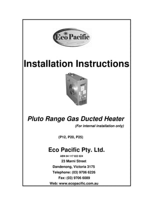
  • 1. Installation Instructions Pluto Range Gas Ducted Heater (For internal installation only) (P12, P20, P25) Eco Pacific Pty. Ltd. ABN 94 117 653 924 23 Marni Street Dandenong, Victoria 3175 Telephone: (03) 9706 6226 Fax: (03) 9706 6089 Web: www.ecopacific.com.au
  • 2. 2 Eco Pacific Pluto Range Gas Ducted Heaters (Installation Instructions) CONTENTS Page Description of the heater 3 General requirements 4 Installation (internal) 5 Pre-commissioning check list 9 Operating instructions 9 Commissioning procedure 11 Final Checks 12 Figures: Figure 1&2: General aspects 3 Figure 3: Required clearances 5 Figure 4: Gas valve connections 7 Figure 5: Power point connection polarity 7 Figure 6: Dimension locations 14 Figure 7: Wiring Diagram 14 Pluto dimensions and specifications Table 1: Specifications data 13 Table 2: Pluto Dimensions 13 Important Notice to Agents, Installers and Purchasers Although Eco Pacific endeavours to provide appliances of a high standard, it is important that you be aware that problems can occur if the equipment is not properly installed. There are standards covering installation, which has been stipulated by the Australian Gas Association, and the guidelines for installation as written in this booklet are in accordance with those standards. If an appropriately qualified person is not used to install the equipment or if the equipment is not installed according to the guidelines provided, then Eco Pacific will not be able to accept responsibility for any problems, which occur as a result. Abbreviations Abbreviation Quantity Units A Amperage Amperes Ph Phases V Voltage Volts kW Heating Capacity kiloWatts MJ Energy MegaJoules h Time Hours Hz Frequency Hertz
  • 3. 3 Description The Pluto class of heaters is a single packaged central heating unit. Throughout these installation instructions reference is made to the aspects of the heater given in Figures 1& 2. Figure 1: General aspects Figure 2: Different elevations As shown in figure 2, the rear side of the unit is considered to be the end, which contains the supply air duct connection. Using the rear panel as an initial reference the front panel contains access to the Printed Circuit Board (PCB) controls, the gas burner and the gas valve. The gas connection is made towards the front on the lower section of the left hand side panel. Access to the fan wheel and motor is achieved on the right hand side.
  • 4. 4 General Requirements The installation of this appliance must conform to the following requirements: 1. These installation instructions. 2. The Australian Gas Association Code, AG 601. 3. Local gas fitting regulations. 4. Local building regulations. 5. Local electrical supply authority regulations. Models These installation instructions cover the Eco Pacific Pluto range of internal heaters. This range of heaters is intended for use with natural gas or LPG. Performance Information on the performance and overall dimensions of each model may be found in Table 1 and Table 2 respectively. The appliance data plate found on the front panel of each heater unit complements this information. Important Notes AUTHORIZED PERSONNEL must install this appliance and must carry out likewise servicing of this unit. Inspection As soon as a unit is received it should be inspected for any damage that may have occurred during transit. If any damage is evident it should be noted on the carrier’s freight bill. Location The Pluto is an internal air heater, designed for installation in either a roof space or underneath a floor space, and for connection to a ducted warm air heating system. Refer to Table 2 for general dimensions. Although the location is usually predetermined please check with the owner’s or dealer’s installation plans. If a location has not been decided on, consideration must be given to the following: 1. The location must provide adequate structural support; space for service access; and clearances for return and supply air duct connections. 2. Care should be taken to locate the unit and ductwork so that the supply air does not short circuit to the return air. 3. Proper electrical supply must be available. 4. Proper gas supply must be available. 5. Clearances, as outlined in the next sub-section, must be provided.
  • 5. 5 Clearances For servicing, a minimum clearance of 300 mm must be provided on all sides of the appliance, with 600 mm required at the front of the unit, as shown in Figure 3. A 300 mm wide walkway must be provided for servicing, in accordance with AG 601, Gas Installation Code. NOTE: Ducting must not intrude on these clearances for servicing, except for connections. Figure 3: Required clearances Installation Procedure The following sequence of installation steps is suggested. Reference is also made to the Final Checklist. 1. Inspect the unit and set in position. 2. Make electrical power connections. 3. Route the gas piping and connect to the unit. 4. Connect all ductwork. 5. Connect the flue. 6. Make electrical control connections. 7. Power up the heating unit. 8. Start and check the system for correct operation. 9. Instruct the owner on operation of the unit and advise on any servicing and maintenance aspects.
  • 6. 6 A) Roof Space Installation 1. The area in the roof space must be capable of supporting the additional load of the appliance. 2. Access must be available to the appliance, by means of fixed access, a normal ladder or steps. 3. A walkway must be provided between the access point to the roof space and the appliance. This walkway must be permanently fixed, capable of carrying the weight of a person, and extend all the way around the appliance. 4. Permanent lighting must be provided at the appliance, with the switch located at the point of entry to the roof space. 5. The unit must be installed on a solid base (fire retardant board exempt), extending 300mm in front of the unit. A minimum clearance of 200 mm between the top of the appliance and any combustible material must be maintained. 6. Ensure that any ceiling insulation material is kept clear of the appliance by a minimum of 300 mm. B) Under Floor Installation The Pluto may be installed under the floor, provided that: 1. A minimum clearance of 1200 mm exists between the underside of the floor joists and ground level. This clearance is to extend from the access opening to the appliance, and around the appliance. 2. Where minimum clearances exist as above, the appliance shall be located within 2 m of the access opening. 3. Where greater clearances than above exist, the appliance may be installed at any distance from the access opening. 4. A minimum clearance of 200 mm between the top of the appliance and the lowest part of the floor structure must be maintained. 5. The appliance is to stand on a level concrete base of at least 50 mm thickness, and provision must be made to drain away any seepage or ground water so that water cannot come into contact with the appliance. 6. Fixed artificial lighting must be provided at the appliance, with the switch located adjacent to the access opening. Fluing The appliance must be flued to the outside environment, in accordance with the Gas Installation Code, AG 601. The size of the circular flue required for each model Pluto is given in Table 2. Lateral flue runs shall not exceed half the total flue run and have a minimum rise of 20 mm per metre run. If the location does not permit this, provision shall be made for a duct to carry the flue vertically off the appliance through the building to terminate in the ambient atmosphere. Gas Piping A licensed gas fitter must install the gas piping. The connection at the appliance is to a ¾” BSP male thread, located at the inlet of the gas control (found at the lower front left hand side of the unit). A single female ¾” BSP flare nut is supplied with the unit for connection to the required gas piping. An AGA approved appliance isolating cock must be installed close to the unit. Gas piping
  • 7. 7 material and size must be in accordance with the Gas Installation Code, AG 601. The gas connection must be tested for any leakage. Do not use an open flame or other source of ignition for leak testing. The following diagram illustrates a typical gas valve showing the location of the gas inlet and outlet and the pressure testing point. Figure 4: Gas valve connections (Note: the valve used may differ slightly from that shown) Electrical Requirements Power Connections Check that the electrical supply meets the values specified on the nameplate and wiring diagram of the unit. The wiring diagram should be found on the front panel of the heater. A 10-ampere general-purpose outlet is required to be positioned within 1.5 m of the appliance. Wiring shall be in accordance with the local supply authority regulations. Ensure that the polarity of the power outlet is correct, as shown in Figure 5. Figure 5: Power point connection polarity A suitable artificial light is to be provided near the appliance to assist with servicing and the switch placed adjacent to the access opening.
  • 8. 8 Room Thermostat The appliance is supplied with either a manual or a programmable electronic room thermostat. The thermostat should be installed on an internal wall, approximately 1.5 m above the floor where it will be exposed to normal room air circulation. It should not be installed on an outside wall or where it is exposed to direct sunlight, heat sources, draughts, or other conditions, which could adversely affect its operation. Generally, the living or dining room is a suitable location, provided there are no cooking facilities or refrigeration appliances on the opposite wall facing the thermostat. Mount the thermostat and route the 24- volt control wiring from the thermostat to the heater unit. Connect the terminals labelled “R” and “W” on the thermostat to the screw type terminals labelled “R” and “W”, respectively, on the PCB connection strip. The heat anticipator setting for the manual thermostat should be set at 0.6 Amps. Ensure that the hole through the wall for wiring to the thermostat is sealed to prevent draughts from affecting the thermostat. The control wiring that passes into the heater should use the supplied cable gland. This gland should be fixed in the hole located at the lower left hand side of the upper access door. For further information concerning the thermostat please refer to the separate thermostat instructions supplied with the unit. Duct Connections All return air duct connections are circular. On all models the supply air ducting is elliptical. Refer to Table 2 for dimensions. A single starting collar is provided with the unit. It is very important to the success of the installation that the duct system be properly designed and installed. Warm Air Ducting From the outlet/supply air duct connection of the unit, install adequately sized ductwork to the outlet/supply air registers. Flexible ducting should be used where noise transfer may be a problem particularly at the duct connection points. All ductwork, fittings and registers shall be sized to comply with AG 706, Design Manual for Indirect Gas Fired Ducted Warm Air Central Heating Systems. It is highly recommended that the ductwork be insulated, especially where it runs through an unheated space. The supply air connection should be transitioned to the proper duct size. All ducts should be suspended using flexible hangers. Ductwork should not be fastened directly to the structure. Care should be taken to ensure that all ducting is free of internal obstructions, free of leaks and adequately supported. Likewise ducting should not be crushed or slack in any manner. Return Air Ducting A return air duct must be provided and should draw air from a central location within the house. The recommended duct length is 6 meters. This ducting may be installed to either or both of the return air connections found on the left and right hand rear sides of the unit. In instances where the unit is drawing air from a building cavity make certain that it is fully sealed. This ensures that outside air is not drawn into the system, which will affect unit performance.
  • 9. 9 Outlet Registers Suitable outlet registers must be provided in all areas being heated. Filters The use of filters is recommended in order to keep the duct system clean and to collect dust, lint and other debris from entering the heating unit. A filter is usually installed in the return air duct. It should be in a position where it is accessible for ease of cleaning. Where a filter is fitted, the return air grille dimensions should be increased by at least 30%. Add-On Cooling Where, either presently or in future, add-on cooling is to be installed the indoor coil section should be installed at least 3 metres downstream of the supply air duct connection. System Balancing Provision for system balancing by using dampers or other suitable means for adjusting airflows must be provided in the duct layout. Fan Adjustment The fan is preset at the factory to operate at high speed. The speed can be changed by changing the wiring to different step points on the socket of the fan scroll. Notes 1. A minimum 30-second delay should be given to allow the fan to reach the selected speed. 2. It is important that the fan speed be set so that discharge air temperature does not exceed 60 ºC. Pre-commissioning Check List • Have all the gas lines been checked for leaks? • Is the blower correctly wired? • Thermostat correctly wired with correct polarity? • Thermostat anticipator set to 0.6 Amps? • Filters clean and in place? • Outlet registers and return air grille are open? • Ductwork sized adequately and correctly installed? Operating Instructions The Pluto heater does not have a standing pilot. It is equipped with an energy saving electronic ignition device, which automatically lights the burner when the
  • 10. 10 thermostat calls for heat. Do not manually light burners with a match or other source flame. Preliminary Set the wall thermostat to the “OFF” position. Open duct registers in rooms. Check gas supply is turned on at gas cock. Lighting Instructions Step 1. Check that the thermostat is set to “OFF”. Step 2. Turn 240 VAC power “ON” at unit. Step 3. Turn the thermostat to “ON” and to a temperature above ambient room temperature. Unit should ignite in approximately 30 seconds. Step 4. For natural gas and LPG units the heater will attempt ignition only once and should ignite, however, attempts ignition again if the flame is lost due to some reason. The PCB on the board rechecks ignition every hour then after. Sequence of Events a. When the thermostat is turned up it calls for heat. b. The appliance control enters a pre purge period of 30 seconds. c. A direct spark ignitor will be energised to ignite the gas after the pre-purge period. d. Simultaneously the main gas valve opens. e. The burner will light and the flame sensor will detect the presence of the flame. The ignitor will de-energise after the flame is sensed. If the flame sensor does not detect the presence of the burner flame, the gas valve will close. f. The room fan will come on after 30 seconds. g. The furnace will remain in operation until the thermostat is satisfied. h. Once the thermostat is satisfied, the gas valve will close and the fan will turn off after approximately 50 seconds. If the unit does not ignite- Step 5. Turn the thermostat to “OFF” for 3 seconds, then back on again. Step 6. Turn the thermostat to “ON”. Unit should ignite in approximately 30 seconds.
  • 11. 11 Often in new installations there is a period of time required to purge the gas line of any air, which may be present. If having proceeded through steps 1-6 and determined that the gas line has been purged of gas and the system still fails to ignite/operate correctly, refer to the Service Instructions and wiring diagram given in the end, or contact the Service Division of Eco Pacific on (03) 9706 6228. Consideration should be given to the other possible causes for the equipment to fail to operate. The PCB LED flashing at varying rates as listed below indicates some of these other problems: 2 flash = system lock out- failed to detect or sustain flame. Check that the flame sensor is connected on to the board and positioned properly above the burner port. 4 flash = High limit or manual overheat switch opened, wait until the auto switch closes, or if manual cut off- see if there is obstruction in the duct, open more registers, manually reset the manual switch and try the ignition from the thermostat again. 5 flash = Flame sensed and Gas valve not energised, check the gas valve. Steady light on = internal failure (microcontroller failure and power on self- check) If the system still fails to operate, please contact Eco Pacific on (03) 9706 6228. Once the unit is operating, set the thermostat to the temperature which satisfies your comfort requirements. Commissioning Procedure 1. Check the burner pressure setting. The pressure test point is as shown in Figure 4 and is a 3/8” gland type fitting. The correct pressure for Natural Gas is 0.87 kPa. The correct pressure for LPG is 2.7 kPa. 2. Have the appliance ignite by setting the room thermostat to call for heat by raising the set point above the current room temperature. 3. Having successfully achieved ignition, after a period of 5 minutes, check the airflow at all the registers and adjust the dampers to achieve design air quantities. Maximum air delivery temperature at the outlets should not exceed an average of 50 ºC. Maximum air delivery temperature at the supply air connection should not exceed 60 ºC, or 55 ºC for Extra Air models. If this requirement is not met the blower speed must be increased. 4. Check the operation of the over temperature switch by restricting the airflow (the over temperature switch will automatically reset on cooling down). Restricting the airflow can be achieved by blocking the area of the return air grille. 5. Turn the room thermostat to “OFF”. The fan should stop after a period of approximately 50 seconds. 6. Check the flue for leaks and spillage. Spillage may occur if the flue installation is faulty. If so this situation must be corrected.
  • 12. 12 The user must be instructed on how to correctly operate the system All units are fitted with automatically resetting high temperature limit switches. It is important to leave a minimum number of registers open otherwise the unit will cut out on the high temperature limit (a typical number is approximately 3, 6 & 8 for P12, P20, & P25 respectively). In the case of power failure, the unit will go to lockout and the high temperature limit switch may be activated. When power is restored the high temperature limit will automatically reset but the thermostat will have to be turned down and up again to start up the system. Abnormal Operation Should any of the following characteristics occur, advise the user to contact their local Eco Pacific service agent or the local gas authority immediately: • Smell of gas. • Unusual odours from outlet registers. • Smoke or fumes from outlet registers. • Excessive or unusual noises emanating from the appliance. Warnings Advise the user of the following issues: • Do not place articles on or against the heater. • Do not use or store flammable materials near the heater. • Do not spray aerosols in the vicinity of the heater while it is in operation. • The front cover of the heater must be fitted while the unit is in operation. Maintenance Advise the owner/operator of the need to clean any filters if fitted. Never turn a dirty filter around to allow air to flow in the opposite direction. Cleaning or replacing filters regularly keeps the system operating at peak efficiency levels. The frequency at which cleaning or replacement occurs depends upon the hours of operation and the local environment. Final Checks Have all parts of the heater been inspected for damage due to transport? Has a suitable location been selected? Have electrical power connections been made according to all relevant standards? Has the gas piping been connected according to the relevant standards? Has the electrical control wiring been connected to the unit in accordance with the enclosed instructions?
  • 13. 13 Has the inlet gas pressure to the heater been set correctly? Has all the required ductwork been installed properly? Has the correct operation of the unit been tested? Have all the relevant regulatory bodies been advised of the installation? Has the warranty card been completed and returned to Eco Pacific? Has the Installer's Declaration been signed off in the Operating Instructions provided with the heater? Has the consumer been given a copy of the Operating Instructions and instructed on how the system operates? Has the consumer been advised of the system's servicing requirements? General Information Table 1: Specifications data Model Item Pluto 12 Pluto 20 Pluto 20 EA Pluto 25 Pluto 25 EA Heat Input (MJ/h) 55 85 85 110 110 Heat Output (kW) 12 19 19 25 25 Air Flow (L/s at 75 Pa ESP) 325 520 630 690 880 Weight (kg) 35 52 53 65 66 Electrical Power(V/Ph/Hz) 240/1/50 ‘’ ‘’ ‘’ ‘’ Control (V) 24 ‘’ ‘’ ‘’ ‘’ Total Current (A) 3 4 4 5 4 Maximum Add-On Cooling (kW) - 7-10 10 14 16 Table 2: Dimensions (mm), refer Figure 6 below Dimensions / Model → ↓ Pluto 12 Pluto 20 Pluto 20 EA Pluto 25 Pluto 25 EA A Width 760 955 955 960 955 B Depth 280 320 320 380 320 C Height 555 740 740 740 740 D Flue Collar 100 125 125 125 125 E Duct Connection 250 300 350 350 400
  • 14. 14 Figure 6: Dimension locations Figure 7: Wiring Diagram Eco Pacific 30/3/2006
  • 15. 15
  • 16. 16 P L U T OC E N T R A L H E A T I N G R A N G E
  • 17. 17