Download to read offline
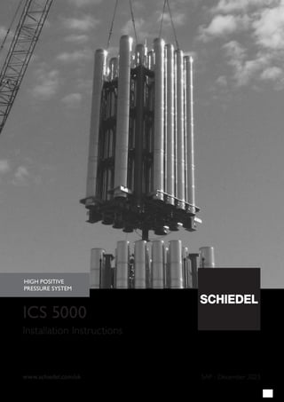
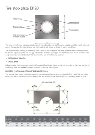
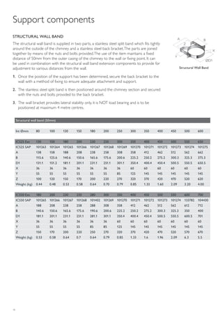
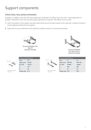
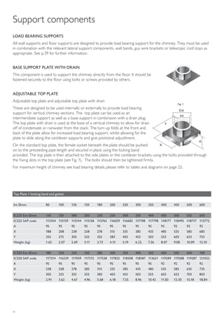


The document provides comprehensive installation instructions for the Schiedel ICS 5000 chimney system, detailing approved specifications, design guidelines, and safety measures. It emphasizes the importance of compliance with European standards, ensuring safe connections to appliances, and proper installation practices. Additionally, it includes necessary precautions for material handling, installation techniques, and essential components for chimney support and fire safety.


