electric boiler user boiler.pdf
•
0 likes•40 views

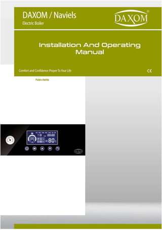
Electric Combi Boiler Properties 3 Level Pump and Additional Pump Option 6 Different Security System 7 Days, 21 Program with Interior Timer Anti Blockage and Freezing Prevention System Different Temperature Value Determination For Each Program Full Modulation, High Efficiency. Under Floor Heating or Radiator Heating Option If Required 3 Level Setting Operating as 3 Phase or Single Phase Operation Conformity with Solar Energy Summer – Winter Mode Option Touch Button and Easy Use Lcd Panel

Recommended
More Related Content
Similar to electric boiler user boiler.pdf
Similar to electric boiler user boiler.pdf (20)
More from DAXOM Gas Water Heaters,Electric Boilers, Condensing Gas Boilers
More from DAXOM Gas Water Heaters,Electric Boilers, Condensing Gas Boilers (20)
Recently uploaded
Recently uploaded (20)
electric boiler user boiler.pdf
- 1. 1
- 2. 1 TO DAXOM USER In order to perform device’s function properly and for your safety follow the instructions mentioned in the user manual of the device during the mounting and the usage of the device. In case of an unauthorized mounting and maintenance, the device will be void from warranty cover. In addition to that, our company will not be responsible from failure or an accident that may occur in the device. Please keep this user manual in good conditions for future reference. 1. SAFETY WARNINGS Device installation must be made by authorized personnel according to instructions that are determined inside this manual. Start-up of device must be made by Authorized Service. Do not try to operate the device by yourself. Connection of water and heating installment of the device must be made as safety. Device can operate with the voltage determined inside this manual according to its model. Suitable system voltage must be provided. When it is supplied electric distribution from any electric resource (like generator) except city electrical distribution network, must be sure that necessary conditions are provided for safety operation of the device. Energy must be provided to device with suitable cable section determined inside this manual. Residual Current Device and grounding must definitely place. Installation of the device must not be made to humidity places and places that can be wet from external factors. Do not keep inflammable, explosive or easy flammable materials or objects near or close the device. This “INSTALLATION AND USER MANNUAL” is supplemental part of the product. Please keep it for apply when it is necessary. Contact with authorized service agency for the new copy in case of lost or damage. This device must only be used as suitable as for its purpose. Producer reject all kinds of liabilities that places or not places in the agreement for damage property or injury indented to person and animals which cause because of consumer wrong using, installation, setting and maintenance. After you unpack the device, be sure that content is in good position and complete otherwise contact with the sales agency that you have purchased the device
- 3. 2 Safety valve outlet must be connected to suitable discharge system. All responsibilities are belong to user in case of any damage that occurs because of any intervention to safety valve. Remove all packing wastes carefully without giving damage to human and environment health. In case of water leakage happens, water feed must be close and authorized service agency must be immediately informed. Hydraulic system operation pressure must be between 1 and 2 bars therefore it must not exceed 3 bars. In case of need reduce water pressure of heater circuit from discharge valve of installment. If the device will not have used for a long time, perform following points are suggested. Bring switch of the device OFF position. Close taps both heating and hot water network. Discharge heating installation and boiler cycle for preventing freezing. Device cannot be used by children or disabled people without helper. In case of having smoked or burning smell originating from device, make switch of the device”OFF” position and contact with authorized service agency. Do not touch the device with wet hand or when outside of device is wet. Do not use substances such as detergent and thinner for the cleaning of the device. Clean outside of the device with damp –dry fabric after make switch of device OFF. Absolutely control temperature of hot water before using. The lifetime of the device which is determined by Ministry of Custom and trade is 10 years
- 4. 3 2. SUGGESTIONS FOR ECONOMICALLY USED Adjust ambient temperature according to your need. Increasing 1 degree of ambient temperature increases your energy consumption about %6. Having homogeneous heating at parts according to intended use that is placed at the heating place, increases saving. By using thermostatic valve for radiators, having adjustable required temperature value for every section increases saving but using room thermosatd and thermoatatic valve at the same time can cause problem For sensing thermostatic valves ambient temperature correctly, curtains or objects that affect air flow must be positioned properly. For sensing room thermostad ambient temperature correctly that it placed, it should be positioned far and proper height from window, object or heat source. Ventilation of heated environment very long time increase the energy lost. Short time ventilation must be made. If it is needed to make long time ventilation, closing valve of ambient radiator or turn the device down provide energy saving. At night time or when you are not at home for a short time, if device temperature is decreased, can be saved while providing keep the temperature at sufficient level. Adjustment of device operation temperature setting according to exterior temperature provides saving. . Use water as consciously. Consciously using water increase saving. 3. CONFIGURATION OF DEVICE *Measurements are mm value. Capacity 60-96 KW a 900 b 600 c 290 d 100 e 500 f 100 g 300 h 200 i 200
- 5. 4
- 6. 5 4. TECHNICAL INFORMATIONS Model Power Dimensions Weight (kW) Y*G*D (mm) (Kg) 3~400 V 50 Hz Electrical Only Heating Without Pump and Expansion Tank UKDAX-60ETP 60 900*600*290 37,8 UKDAX-72ETP 72 900*600*290 37,8 UKDAX-80ETP 80 900*600*290 37,8 UKDAX-96ETP 96 900*600*290 37,8 Technical Informations Heating (Radiator) Min. Operation Pressure bar 1 Max. Operation Pressure bar 3 Min. Setting Temperature °C 10 Max.Setting Temperature °C 80 Connections İnch 1
- 7. 6 5. INSTALLATION OF DEVICE 5.1. Installation Conditions and Safety Warnings Obey minimum distance that is anticipated for installation in order to reach the device for making maintenance and repair. For Correct Device Installation; Installation must not be made on the cooker or similar cooking devices. Do not leave combustion products inside device installed room. Heating sensitive walls (for example wooden walls) must be protected with steady insulation. BOILER INSTALLATION MUST BE MADE BY AUTHORISED PERSONNEL
- 8. 7 Before the installation, wash the all system pipes must be washed carefully for removing any residual things that can give damage to operation of the device. When heating system increases over 3 bar, water disposal starts from safety valve. Device installation place must be far way from blockers, obstruction parts and bulges during repairing and maintenance. There must be sufficient space around the device for maintenance and repair. Electric connection of the device must be made with suitable cable, fuse and residual current device and grounding absolutely must be made. Installation wall of the device must be as durable as carrying the weight of the device. 5.2. Wall Installation Of Device Drill installation holes to chosen place according to conditions stated above and fasten fixing plugs. Control durability of device by screw on to holes from up and down. 5.2.1. Connection of Heating System and Water Installation Heating system must be drawn with suitable diameter pipe for providing enough circulation of heating water. Choosing radiator pipes smaller than it is needed, fitting constriction or blockage can cause inability circulation of heating. Connections that are made to device must be easy removable when it is needed. There must be separate cutoff valve at radiator inlet and outler of device also there must be silt trap between valve line and device. There must be valve and silt trap at cold water inlet. Make sure that installation wall can carry device weight and installation part is fixed as safely
- 9. 8 5.2.1.1. Filling Of Boiler After installment is completed, boiler is needed to fill. This process must be done by implementing following instructions. Open boiler inlet valve of installment. Open any tap connected to device hot water outlet. (preferably nearest tap). Air inside boiler will be discharged from tap. Close the tap after air discharged from tap and continuous water flow start. 5.2.1.2. Filling Heating System For UKDAX-xxETP this process is made with filling valve which is connected to heating system. It is needed to make connection with valve from cold water system to heating system. Filling valve must be positioned as close to device and sight pressure gauge of device. After filling valve, there must be silt trap. Filling process must be done by implementing following instructions. Open heating system water filling valve. When water pressure indicator reaches between 1-1,5 bar, close the filling tap. Discharge the accumulated air inside radiators by opening air relief cock placed in side of radiators and close when water starts to flow. When the accumalted air inside radiators discharge it can be decrease at heating system water pressure. Make sure that heating system water pressure is between 1 and 1,5 bar. If decreases, complete by opening filling valve After heating system is filled, must be studiously controlled if there is water leakage or not. If filling valve is forgot as open and heating system pressure exceeds 3 bar, drainage starts from safety valve inside device.
- 10. 9 Electric Boiler –Boiler and heating installation sample principle scheme
- 11. 10 Electric Boiler – Heaitng-only installation sample principle scheme 5.2.2. Electric Connection Electrical installation must be done by authorized person according to device capacity and with suitable diameter cable. Electric of device must have suitable specification for for cut off device power and residual current device that has amper value and fuse separately. Fuse must be near to device. Grounding of device must absolutely be done. If there is not grounding at the place that the device is installed, grounding must be made for device by authorized person. Operative of grounding must be controlled in determined periods. Fuse must locate near the device and device cable must not be strained while connect to fuse. Connection of cables to fuse must be made by authorized person.
- 12. 11 Model Power (KW) Phase& Voltage (V) Current Drawn (A) Fuse & Residual Current Device (A) Cable Section (mm) UKDAX- 60ETP 60 3~400 3*90,9 3*100 5*25 UKDAX- 72ETP 72 3~400 3*109,1 3*125 5*35 UKDAX- 80ETP 80 3~400 121,2 3*150 5*35 UKDAX- 96ETP 96 3~400 145,5 3*160 5*50 Make sure that cables are connected to correct places. . Loose cable connections can be caused to accidents. Cable sections that are calculated according to device capacity and cable length, residual current device and fuse amper values can be seen at the following table. Cable sections at this table are calculated for maximum 10m. Consult your authorised service for more than 10m cable length.
- 13. 12 6. DEVICE OPERATION AND USAGE 6.1. LCD Display Operating Condition and settings of the device can be follow from LCD panel. Radiator Operation Indicator Floor Heating Indicator Days of Week Time programming. Can be made 7 pcs time programming Hour Capacity Indicator Ready to Operation Indicator Hot Water Heating Indicator Radiator Heating Indicator Restart temperature difference indicator ΔT Temperature Difference Indicator Pump Operation Indicator Freezing Prevention Indicator Temperature Indicator
- 14. 13 6.2. Control Buttons Control of the device is done with buttons placed under the LCD Display. 6.3. Operation Of Device First operation of the device must be absolutely done by authorized service. Our company is not responsible from damages and accidents which can be occured with intervention to device by unauthorized people. Before operating the device, suitability of all connections of mechanics and electrical must be controlled. Heating system must be completely filled and radiator vent must be done. Our company is not responsible from damages and accidents which can be occur because of wrong connection. Follow following points for operation of device. . Make sure that device water and radiator valves are open . Open residual current device then fuse. After all symbols on the LCD screen appear a few min, LCD screen will be as in the following
- 15. 14 Hold 2-3 min to button for device ON . Device keeps last settings in its memory before OFF. When it is ON again, starts to operate with same settings. When operation off device is set as boiler and radiator heating before OFF position if boiler temperature is lower than set temperature, device operates for boiler heating. and symbols are seen with “heating” and “shower”, symbol blinks. If boiler temperature is equal or over the set temperature , device operates for radiator heating. and symbols are seen with “heating” and “shower”, expression.
- 16. 15 When operation of the device is set as boiler heating before OFF position if boiler temperature is lower than set temperature, device operates for boiler heating and symbols are seen with “heating” and “shower”, expressions symbol blinks. If boiler temperature is equal or more than the set temperature, device passes to standby position. When operation of the device is radiator heating before OFF, device operates for radiator heating. is seen with “heating” word. after pump operates about 1 min, device starts to radiator heating. is seen. Warning beep is heard after process of pressing knob. For long time pressing knobs (forexample 2-3 seconds), before hearing warning warning beep, it does not mean pressing knob.
- 17. 16 6.4. Operation Parameter Setting 6.4.1. Day and Hour Setting Switch Off the device. Hold button 5-6 seconds. Days start to blink.
- 18. 17 Days are set by pressing with one second intervals to or buttons. Press button hour blinks. By pressing or one second interval hour is set between 0 and 23
- 19. 18 Press button , minute blinks. By pressing or button one second interval min set between 0 and 60. By pressing button or if not pressing any button for a 10 sec , exit from setting menu by saving settings.
- 20. 19 6.4.2. Radiator Temperature Setting While or symbols are seen at LCD Display, (when device is operating for radiato system) radiator heating setting can be made between 35 oC and 80 oC by pressing or buttons. While radiator heating setting is made, “Water Temp” expression fizzle out, setting temperature value starts to blink. While the device is operating for boiler heating, device operation mode must be changed as radiator heating for setting radiator temperature. At the end of the process, device must be taken to previous operation mode. (Check 6.4.8) After 2 sec later setting completed, device operation temperature and “Water Temp” expression are seen at the LCD. Reaching seeting temperature of device may take time. After tap water heating is completed, radiator heating does not start immediately, radiator heating starts after pump operates for a while for temperature balance.
- 21. 20 6.4.3.Boiler Temperature Setting Boiler temperature setting ; and symbols are seen at LCD Display. When symbol blinks. (when device operates for boiler heating ) setting can be made between 30 oC ile 65 oC by pressing or . If operation mode is set as boiler heating, it is possible to change boiler temperature at standby mode. While radiator heating is operating, for setting temperature of boiler ,it is needed to change operation mode of the device as boiler heating. At the end of this process, device must be taken to previous operation mode. ( Check 6.4.8) After 2 sec later setting completed, device operation temperature and “Water Temp” expression are seen at the LCD
- 22. 21 After device heats the boiler, it operates for radiator heating. Boiler heating starts again when decreases 7C from set temperature. 6.4.4.Temperature Difference Setting Tempereature difference between Heating exit and Heating return of device can be set. While the device is in normal operation mode, Enter setting menu by pressing 2-3 seconds. Boiler heating is always priority
- 23. 22 Press the button one second interval until is seen. Temperature difference start to blink. ΔT temperature difference is set with or buttons. tuşuna basılarak ayar menüsünden çıkılır.
- 24. 23 6.4.5. Room Thermostad Connection It is possible to command device with room thermostad. In this way, device operates according to temperature of environment of room thermostad place. Room thermostad temperature must be done by authorized service while first operation of device is making. 6.4.6. HEATING MODE SETTING Device can be set according to floor heating (low temperature) or radiator heating system. In this way, overheating is prevented especially for floor heating systems. While the device is operating at floor heating mode max 55 degrees, it can be set max 80 C at radiator heating mode. Devices connected to floor heating systems will be taken to floor heating mode by authorized services at the time of first operation. In this way, in this case, it will be impossible to change heating mode for users by consciously or by mistake. For radiator heating modes, is users want, they can provide operation of device max 55C by changing into heating mode to ground heating mode. While symbol is seen at radiator mode , it is not seen at floor heating mode. While device is operating regulary Enter the setting menu by pressing 2-3 seconds Press button one second interval until is seen. Heating mode choosing indicator blinks.
- 25. 24 0” is chosen with or symbols for floor heating mode. “1” is chosen for radiator heating For floor heating systems because of heating mode is set from inside device by authorized service, in this menu “0” set can not be changed.
- 26. 25 Exit setting menu by pressing button. 6.4.7. Capacity Setting Device can operate with 3 different capacities. P1 mean is 1/3 capacity, P2 mean is 2/3 capacity, P3 mean is full capacity. Forexample if the device is 24kw, P1: 8 KW, P2:16kw, P3:24 KW. While device operates regularly Enter setting menu by pressing button 2-3 seconds. Definitely temperature must not set over 55C for floor heating systems. In case of setting our companies is not responsible from damages or accidents that may occur.
- 27. 26 Press one second interval until is seen. With or buttons, device capacity can be set as P1,P2 or P3. Indicator lights change according to chosen capacity.
- 28. 27 Exit menu by pressing button. 6.4.8. Operation Mode Setting Device can operate 3 different operation mode. Radiator Operating Mode: Device only makes radiator heating. boiler heating does not occur. Boiler Operation Mode: Device only heats the boiler. This mode can also named as heater or summer mode. Radiator and Boiler Operation Mode.: Device makes both radiator heating and boiler heating. Priority is always for boiler heating. While radiator heating is being done, if it is needed boiler heating device stops radiator heating and operates for boiler heating.
- 29. 28 While device operates regularly Enter setting menu by pressing button 2-3 seconds Press button one second interval until “heating” and / or “shower” blink.
- 30. 29 With or button preferred mode is chosen. If “heating” is chosen device only operates for radiator heating. If shower” is chosen device operates for boiler heating. If “heating” and “shower” are chosen at the same time device operate for both radiator and boiler heating.
- 31. 30 Exit setting menu by pressing button. 6.4.9. Time Programing Setting The device can be programmed daily and weekly for radiator heating. With 7 different time programs, the start and end times of the program, the operating temperature of the device during program and the ΔT temperature difference can be adjusted. If the programming has been made and activated, the device will not be heated during periods of time that are not programmed. Device waits at standby position for heating. Time program can be active or inactive with button. When the time program is active, the current program number is displayed. While the device is in normal operating position; Press button 2-3 second and enter setting menu.
- 32. 31 Press button one second interval until “Timing Time Phase” is seen. Timing program blink. By pressing or buttons timing program is chosen between 1 and 7. Press button.
- 33. 32 With or buttons timing program is “ON” position. If it stays at “OFF” position, can not be entered to timing program. By pressing button week day / days are chosen. With or buttons, intended week day or days can be chosen. Week days are group as in the following. All days can be chosen (SUN. MON. TUES. WED. THUR. FRİ. SAT.)
- 34. 33 Weekends (SUN. SAT.) Weekdays (MON. TUES. WED. THUR. FRI.) Days can be chosen one by one
- 35. 34 Press button , program start hour blinks. With or buttons, program start hour is determined. Press button. Program start minute blink.
- 36. 35 With or buttons, program start minute is determined. Press button. Program finish hour blink. With or buttons program finish hour is determined
- 37. 36 Press button. Program finish min blink. With or buttons program finish minute is determined. Press button. Temperature indicator blink.
- 38. 37 Operation temperature of intendent program is chosen with or buttons. Press button. symbol and exit / return temperature difference adjustment indicator blink. Intendent ΔT (exit /return temperature difference )at selected program is chosen with or buttons
- 39. 38 Press . Other intetendent time program is chosen and repeat starting from 3rd step. Setting all time programs are not necessary. You can set time programs between 1 and 7 as much as you want. Because of unadjusted programs remain “OFF” position, they will not be active. After programming is finished, when it is pressed to button or not pressing any button with 10 seconds can exit from setting menu by saving settings.
- 40. 39 6.5.Make The Device OFF 6.5.1. Temporary OFF For short time OFF periods, provide the device OFF by pressing button 2 or 3 seconds. By activating electric supply, device will be protected by following steps If temperature of water inside device reduces under 5C, device operates fpr a while by getting involved pump an heating. Buring antifrost time is seen at LCD display.
- 41. 40 Anti – Blockade Function: Pump and 3 way valve inside the device start to operate for a short time once every 18 hrs. 6.5.2. LONG TERM OFF If you do not operate the device for a long time, make the circuit breaker OFF after pressing button 2or 3 seconds. In this case, because of freezing prevention of the device will not operate discharge the water inside device in case of freezing risk
- 43. 42 8. REPAIR AND SERVICE During guarantee time of product we provide Free of Charge Service to users against defect of related materials and production about device. When you meet with problem while using, please contact with our after sales service department. Repairing and maintenance of the device by unauthorizedperson will make the device out of warranty. Afterwards our company will not responsible from damages and accidents. 9. TROUBLE SHOOTING Failure Code Failure Solution E0 Water pressure is not enough Set the water pressure between 1 and 2 bars Water pressure switch damage Call authorized service E1 Heating sensor damage Although you wait for a while if you still have seen the same code, call the authorized service. E3 Warning of water temperature is over 85 oC Device will start to operate a few min later. Warning of limit thermostad is in circuit When the temperature is below 85 degree, it is going to start to operate E4 Although you wait for a while if you still have seen the same code, call the authorized service. Pipe is blocked or valve is closed Control if tis closed valve or not at heating installation and clean silt trap. E5 Pump damage Call the authorized service. Flowmeter damage
- 44. 43 PROBLEM CAUSE No Light At Control Pannel Buttons Not Operate Burning Smell Heating Temperature is not t Enough Boiler Not Heat Water Leakage at connections Frequently water decrease Water Leakage From Safety Valve SOLUTION WAYS No Electric Residual Current Device or Fuse is OFF Connection Problem of Power Card or Control Card LCD Card Damage ● ● Control if there is electric or not Control residual current device and fuse Call authorised service Not proper connections Sealing Gasket is damaged ● Connections must be made again Sealing gaskets must be renew Key pad damage PCB Damage ● Call authorised service Unproper Cable Using Loose Connection ● Turn Off the device , call authorised person High Pressure ● Discharge excess water from discharge valve Device is set to radiator heating mode Flow Sensor Damage ● Control Device Setting Call Authorised Service Resistance Damage Limit Thermostad Cut Off Current Triac Damage Control Card Damage ● ● Call Authorised Service Not Enough Water Pressure ● Control Water Pressure Water Leakage at installation pipe ● Remove leakage from heating system installation
- 45. 44 Isı Cihazları Sanayi ve Ticaret Limited Şirketi Namık Kemal Mah. Marmara Cad. No:74 Ümraniye - İstanbul Tel. : +90 216 369 85 36-37 Fax : +90 216 385 95 45 E-Mail : info@daxom.com General Service : Namık Kemal Mah. Marmara Cad. No:74 Ümraniye - İstanbul Tel. : +90216 360 71 21-22 Fax : +90216 360 72 25