
Recommended
More Related Content
What's hot
What's hot (20)
Viewers also liked
Viewers also liked (20)
Similar to Refrigeration vtu atd notes pdf download
Similar to Refrigeration vtu atd notes pdf download (20)
Recently uploaded
Recently uploaded (20)
Refrigeration vtu atd notes pdf download
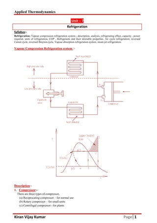
- 1. Applied Thermodynamics Kiran Vijay Kumar Syllabus:- Refrigeration: Vapour compression refrigeration system ; description, required, units of refrigeration, COP , Refrigerants and their desirable properties. Air cycle Carnot cycle, reversed Brayton cycle, Vapour absorption Vapour Compression Refrigeration system Description:- 1. Compressor:- There are three types of compressor, (a) Reciprocating compressor – for normal use (b) Rotary compressor – for small units (c) Centrifugal compressor - for plants Unit – 7 Refrigeration Vapour compression refrigeration system ; description, analysis, refrigerating effect, capacity , power COP , Refrigerants and their desirable properties. Air cycle Carnot cycle, reversed Brayton cycle, Vapour absorption refrigeration system, steam jet refrigeration. Vapour Compression Refrigeration system :- compressor, for normal use for small units for plants Page 1 analysis, refrigerating effect, capacity , power COP , Refrigerants and their desirable properties. Air cycle refrigeration; reversed refrigeration system, steam jet refrigeration.
- 2. Applied Thermodynamics Kiran Vijay Kumar Page 2 In normal reciprocating compressor either single cylinder or multi cylinder compressor is used. The refrigerant is sucked & compressed but due to clearance volume given it’s volumetric efficiency reduces given by equation, vol= ,at evaporator temperature & pressure 2. Condenser:- A device which rejects heat from refrigerating system. There are 3 types of condenser, (a) Air cooled – for small units (less than 5 ton refrigerating capacity) (b) Water cooled: - classified as, i. Shell and tube ii. Shell and coil iii. Double tube (c) Evaporative condenser – for large plants The shell & tube condenser is most commonly used in house hold refrigerator, evaporative condenser is used in industry where water is used as refrigerant. 3. Expansion device:- It serves two purposes, i. Reduces pressure condenser to evaporator. ii. It regulates flow of refrigerant to evaporator depending on load. Normally expansion devices are not preferred since they are not very efficient to get required result. We normally use throttling valve or capillary tube for expansion in reducing pressure with required efficiency. 4. Evaporator:- It is a component in which heat is removed from refrigerating space (i.e. Air, brine, water etc.) required to be cooled by evaporating refrigerant. Two types, i. Flooded evaporator- it is used where liquid refrigerant covers entire heat transfer surface. ii. Dry evaporator- it is used where liquid refrigerant covers a part of heat transfer surface. Refrigerating effect, capacity and co-efficient of performance of Refrigerator:- The amount of heat removed from refrigerated space or the cold body per unit mass of the refrigerant is called as refrigerating effect. (i.e. = ) It is expressed as ton of refrigeration. One ton of Refrigeration:- It is the amount of heat to be removed from one ton of water at 0°C to convert one ton of water into ice at 0°C within 24 hours. In SI Units. 1 ton of refrigeration = 211kJ/minute = 3.517kW. Coefficient Of Performance, COP:- It is the ratio of heat removed from refrigerated space (cooling effect) to the required energy input. COP refrigerator = COPR = =
- 3. Applied Thermodynamics Kiran Vijay Kumar COP of heat pump, COPHP= Refrigeration Cycle:- The cycle process executed by the refrigerant the produce the required refrigeration. i. Gas refrigeration a) Carnot gas b) Ideal Air Refrigeration cycle. ii. Vapor refrigeration cycle a) Vapor absorption cycle. b) Vapor compression cycle. Air standard cycle:- i. Reversed Carnot cycle (Carnot gas refrigeration cycle, Carnot refrigerator): Figure shows schematic diagram of Temperature Process 1-2: Isentropic Compression process, Work is done on the substance by the surrounding w1-2 = q1-2 = 0 Process 2-3: Reversible Isothermal Cooling rejected by the refrigerant to sink at Temperature T W2-3 = q2-3 = Process 3-4: Isentropic Expansion of refrigerant process, Work is done by the substance on the surroundings. W3-4=q3-4=0 Process 4-1: Reversible Isothermal heating refrigerated (cold chamber) maintained at W4-1 = q4-1= ∴ COPR = ! "#$ COP of heat pump, = ∴ COPHP = % "#$ The cycle process executed by the refrigerant the produce the required refrigeration. Gas refrigeration cycle, Carnot gas refrigeration cycle. Ideal Air Refrigeration cycle. refrigeration cycle absorption cycle. compression cycle. Reversed Carnot cycle (Carnot gas refrigeration cycle, Carnot refrigerator):- Temperature Vs entropy for Carnot refrigeration cycle. Compression of refrigerant (working substance) from state 1 to St is done on the substance by the surroundings. ---------------------------------(1) Reversible Isothermal Cooling of refrigerant in the inter cooler during this process heat is rejected by the refrigerant to sink at Temperature TH. &'( ) * = TH(s3-s2) ---------------(2) of refrigerant (working substance) from state 3 to State 4 during this is done by the substance on the surroundings. ----------------- (3) heating of refrigerant from the heat taken up from cold chamber) maintained at Temperature TL. &'(= TL(s1-s4) -----------------(4) Page 3 The cycle process executed by the refrigerant the produce the required refrigeration. - cycle. state 1 to State 2 during this the inter cooler during this process heat is (2) state 3 to State 4 during this from the heat taken up from the place to be (4)
- 4. Applied Thermodynamics Kiran Vijay Kumar Expression for Refrigeration effect and COP Net work transfer per unit mass for the cycle is Wnet = w1-2+w2-3+w From 1st law, i.e. w1-2+w2 From equation (1),(2),(3) & (4) ∴ Wnet Since, s1= s3 & s2= s4 Wnet We know, COP = +,-./01.201 = 3& COPCarnot = 3 This indicate that the COP increases as (T efficient system but it is not suited for following reasons, 1) It is difficult to maintain Isothermal temperature for heat absorption &rejection 2) Compression & expansion process take place very slowly by quasi very long time. ii) Reversed Bray ton cycle( Bell-Coleman Cycle, ideal air refrigeration) Assumption made in analysis of ideal cycle, 1) The working fluid is air. 2) Air behaves as perfect gas. 3) All processes that the working 4) There are no pressure losses in the piping connecting the various components and also exchanger. 5) Flow is steady and one dimensional. 6) Change in kinetic energy and potential energy of working substance is Expression for Refrigeration effect and COP:- mass for the cycle is, +w3-4+w4-1 ∮ 5 = ∮ 2-3+w3-4+w4-1 = q1-2+q2-3+q3-4+q4-1 = TH(s3-s2)+ TL(s1-s4) net = (TH- TL) (s1-s4) ,-./01.201 67,2 = +89: 67,2 TL3s1 s4@ &A &B@3(1 (4@ CD 3E%FE!@ This indicate that the COP increases as (TH- TL) decreases, theoretically Carnot cycle is most efficient system but it is not suited for following reasons, It is difficult to maintain Isothermal temperature for heat absorption &rejection Compression & expansion process take place very slowly by quasi-static process whi Coleman Cycle, ideal air refrigeration):- ssumption made in analysis of ideal cycle, ll processes that the working substance undergoes are reversible. There are no pressure losses in the piping connecting the various components and also Flow is steady and one dimensional. hange in kinetic energy and potential energy of working substance is negligible (i.e. E Page 4 decreases, theoretically Carnot cycle is most It is difficult to maintain Isothermal temperature for heat absorption &rejection. atic process which takes There are no pressure losses in the piping connecting the various components and also in the heat negligible (i.e. EK=0, EP=0).
- 5. Applied Thermodynamics Kiran Vijay Kumar Page 5 Figure shows schematic diagram & T-s diagram for Bell-Coleman cycle, For ‘m’kg of mass flow rate, Process 1-2: Isentropic compression of air from state 1 to state 2. During this process work done on air by surrounding, GH G: = ( IH I: )(γ-1)/γ ------------------------ (1) & also compressor work= Wc = W1-2= m (h2-h1) = mCp (T2-T1) ------------ (2) Process 2-3: Constant pressure cooling of air in inter cooler, W2-3=Q2-3=0 ------------------ (3) Process 3-4: isentropic expansion of air from state 3 to state 4. During this process work is done by air on the surroundings. GJ G8 = ( IJ I8 )(γ-1)/γ ------------------- (4) & also Expansion work, WE = W3-4= m (h3-h4) = mCp (T3-T4) --------------- (5) Process4-1: Constant pressure heat removed by air in the cold chamber so that it comes back to original state to complete the cycle. Heat added, Qin= m (h1-h4) = mCp (T1-T4) ------------------- (6) Expressions for Refrigeration effect and COP:- We know, COP = K7 67,2 = K7 6LF6M From equation (2), (5) & (6) COP = N/(G:FGH) N/O(GHFG:)P(GJFG8)Q = R SH9SJ S:9S8 TF Since , P2=P3 & P1=P4 From equation (1) & (4) we get, GH G: = GJ G8 =( IH I: )(γ-1)/γ ∴ COP = U V WX WU ( Y9U Y ) ZFU = U [] ( Y9U Y ) ^FU Analysis of an ideal Mechanical Vapor Compression refrigeration cycle:- Assumption, i. The compression process in compressor is isentropic. ii. The refrigerant enters compressor as dry saturated vapor. iii. There is no pressure loss in piping connection of various components. iv. The flow of refrigerant is steady & one-dimensional. v. Change in kinetic and potential energy of refrigerant is negligible
- 6. Applied Thermodynamics Kiran Vijay Kumar The schematic diagram of mechanical vapo corresponding T-s and p-h diagram, Process 1-2: Isentropic compression of refrigerant on refrigerant by the surroundings. At the end of the process refrigerant will be supper heated to state. Compressor work, Wc = W Process 2-3: Constant pressure condensation liquid. Process 3-4: Throttling expansion of the refrigerant from condenser pressure to evaporator pressure. h3=h4 Process 4-1: Constant pressure vaporization vapor. In this process heat absorbed by refrigerant from refrigerating space. Heat added=refrigerating effect, We know, COP = 6L ∴ COP = (_ (_ Refrigerant:- It is the primary substance which is used for absorbing and transporting heat in refrigerant. Refrigerant absorb heat at low temperature & pressure (i.e. compressor) to high temperature & pressure (i.e. condenser) Two types, i. Primary refrigerant: - refrigerant to condenser. For e.g. NH3, CO2, SO ii. Secondary refrigerant: - Substances air, water, brine etc. Selection of refrigerant:- It depends on thermodynamic, physical &chemical property. Thermodynamic Properties for good refrigerant i. Evaporation & Condensing Pressure should not be high to necessitate heavy construction and high cost. atic diagram of mechanical vapor compression refrigeration cycle is shown with the sentropic compression of refrigerant from state-1 to state-2. During this process work is done on refrigerant by the surroundings. At the end of the process refrigerant will be supper heated to W1-2 = m(h2-h1) onstant pressure condensation of the refrigerant in the condenser till it become saturated of the refrigerant from condenser pressure to evaporator pressure. Constant pressure vaporization of the refrigerant in evaporator till it becomes vapor. In this process heat absorbed by refrigerant from refrigerating space. Heat added=refrigerating effect, QL = Q4-1 = m (h1-h4) QL = m (h1-h3) , since h3=h L = `(a1 a3) `(a2 a1) _UF_d) _XF_U) It is the primary substance which is used for absorbing and transporting heat in refrigerant. Refrigerant absorb heat at low temperature & pressure (i.e. compressor) to high temperature & pressure (i.e. refrigerant which cool substance by absorption of heat of evaporation & transport SO2 etc. Substances which cool required space by absorbing sensible heat only. It depends on thermodynamic, physical &chemical property. for good refrigerant:- Evaporation & Condensing Pressure:- Evaporator pressure should be +ve. The condenser pressure should not be high to necessitate heavy construction and high cost. Page 6 r compression refrigeration cycle is shown with the 2. During this process work is done on refrigerant by the surroundings. At the end of the process refrigerant will be supper heated to vapour of the refrigerant in the condenser till it become saturated of the refrigerant from condenser pressure to evaporator pressure. becomes dry saturated =h4 It is the primary substance which is used for absorbing and transporting heat in refrigerant. Refrigerant absorb heat at low temperature & pressure (i.e. compressor) to high temperature & pressure (i.e. which cool substance by absorption of heat of evaporation & transport absorbing sensible heat only. For e.g. Evaporator pressure should be +ve. The condenser pressure
- 7. Applied Thermodynamics Kiran Vijay Kumar ii. Critical Pressure and Temperature & critical temperature has to be high for better heat transfer rate. iii. Freezing Point: - It should be low to operate at high temperature. iv. Latent Heat and Specific Heat: - Specific heat should be low so less liquid flash into vapor in expansion & high refrigerating effect v. Liquid & vapor density: - It should have high specific volume to get low vapor density to have smaller suction, discharge line & displacement volume. vi. Coefficient Of Performance (COP) and compressor work work input (in kW or TR). Chemical property for good refrigerant i. Inflammability: - Should not be flammable & non explosive. ii. Toxicity: - Toxic refrigerant should not be used in domestic refrigerator & comfort AC. iii. Solubility in water: - It should have low affinity to water to prevent formation of ice in tubes & choking of capillarity tube. iv. Material of construction: - It should not react chemically (corrode) material of construction. For e.g. for construction of cooling coil is made from Cu instead of Fe. Physical property for good refrigerant i. Thermal conductivity: - It should have high thermal ii. Viscosity: - Should be low for low pumping power & high heat transfer rate. iii. Leak tendency: - It should be low & detection should be easy. Vapor Absorption Refrigeration System (VAS) VAS is a heat operated unit which uses from absorbent. Construction:- In this system absorber-generator assembly is used to compress the working substance which is connected to condenser, expansion valve & evaporator. In this system water as absorbent. Hence this is called Aqua Critical Pressure and Temperature: - Critical pressure should be low to give low condensing pressure critical temperature has to be high for better heat transfer rate. It should be low to operate at high temperature. Latent heat should be high for greater amount of heat extraction. e low so less liquid flash into vapor in expansion & high refrigerating effect It should have high specific volume to get low vapor density to have smaller suction, discharge line & displacement volume. (COP) and compressor work: - COP should be high & low compressor Chemical property for good refrigerant:- Should not be flammable & non explosive. Toxic refrigerant should not be used in domestic refrigerator & comfort AC. It should have low affinity to water to prevent formation of ice in tubes & choking It should not react chemically (corrode) material of construction. For e.g. for construction of cooling coil is made from Cu instead of Fe. property for good refrigerant:- It should have high thermal conductivity for better heat transfer rate. Should be low for low pumping power & high heat transfer rate. It should be low & detection should be easy. Vapor Absorption Refrigeration System (VAS):- VAS is a heat operated unit which uses refrigerant to alternatively absorb and liberate heat generator assembly is used to compress the working substance which is connected to condenser, expansion valve & evaporator. In this system ammonia is used as refrigerant & water as absorbent. Hence this is called Aqua-ammonia absorption system. Page 7 Critical pressure should be low to give low condensing pressure Latent heat should be high for greater amount of heat extraction. e low so less liquid flash into vapor in expansion & high refrigerating effect. It should have high specific volume to get low vapor density to have smaller ould be high & low compressor Toxic refrigerant should not be used in domestic refrigerator & comfort AC. It should have low affinity to water to prevent formation of ice in tubes & choking It should not react chemically (corrode) material of construction. For e.g. for better heat transfer rate. refrigerant to alternatively absorb and liberate heat generator assembly is used to compress the working substance which is ammonia is used as refrigerant &
- 8. Applied Thermodynamics Kiran Vijay Kumar Working:- Ammonia vapor (weak solution) is readily absorbed in evaporator. The temperature of soln. tend to ri heat of soln.(QA) and maintaining constant temperature ammonia is pumped to generator where heat (Q passed to condenser. The weak soln. from generator is passed back to the absorber by reducing temperature & pressure using heat exchanger & reducing valve respectively weak soln. to QA & QG). The ammonia vapor condense in condenser, throttled by expansion valve & then evaporates in evaporator by absorbing heat from surroundings. Steam jet refrigeration:- A simple steam jet refrigeration system. flash chiller. Due to flashing (evaporation) of some liquid, the water gets chilled to desired temperature. The pressure in flash chamber is maintained 7 is recirculated after taking up the load in cooling coil. The amount of water vaporized is compensated by making up water at state-6 entering through throttle valve. Water vapor at state ejector driven by motive steam at 1. The compressed water vapor at4 is then condensed to 5 and pumped back to boiler. E.g. 1 A vapor compression refrigerator of 10ton capacity using Freon temperature of -100 C and condenser (i) Mass of Freon-12 (ii) Power input (iii) COP If CP(vapor) = 0.56kJ/kg/K and CP(liquid) What is the change in above quantity when F Solution: Given: T1=-100 C ; T2=300 C ; capacity=10ton= From table, Temperature Specific enthalpy ( in kJ/kg) hf T1=-100 C=263K 26.851 T2=Tsat2=+300 C=303K h3=h4=64.539 (weak solution) is readily absorbed in water in absorber at low pressure from soln. tend to rise, while absorber is cooled by circulating water, absorbing ) and maintaining constant temperature using heat exchanger. A strong soln. rich in is pumped to generator where heat (QG) is supplied from external source. The ammonia vapor is passed to condenser. The weak soln. from generator is passed back to the absorber by reducing temperature & pressure using heat exchanger & reducing valve respectively (i.e. heat exchanger preheats & The ammonia vapor condense in condenser, throttled by expansion valve & then by absorbing heat from surroundings. A simple steam jet refrigeration system. Water at state-9 expands to 11 through throttle vale into (evaporation) of some liquid, the water gets chilled to desired temperature. The pressure in flash chamber is maintained at corresponding saturation temperature. The c 7 is recirculated after taking up the load in cooling coil. The amount of water vaporized is compensated by 6 entering through throttle valve. Water vapor at state-2 is compressed to4 by ve steam at 1. The compressed water vapor at4 is then condensed to 5 and pumped Worked Example vapor compression refrigerator of 10ton capacity using Freon-12 as refrigerant has evaporator C and condenser temperature of 300 C. Assume simple saturation cycle determine: (liquid) = 1.003kJ/kg/K What is the change in above quantity when F-12 is sub-cooled & pre-heated by 50 C. Draw C ; capacity=10ton=10×3.5=35kg/s Specific enthalpy ( in kJ/kg) Specific entropy ( in kJ/kg/K) hg sf 26.851 h1=183.058 1.079 =64.539 hg2=199.415 0.2397 Page 8 at low pressure from se, while absorber is cooled by circulating water, absorbing . A strong soln. rich in ) is supplied from external source. The ammonia vapor is passed to condenser. The weak soln. from generator is passed back to the absorber by reducing temperature (i.e. heat exchanger preheats & pre-cools The ammonia vapor condense in condenser, throttled by expansion valve & then 9 expands to 11 through throttle vale into (evaporation) of some liquid, the water gets chilled to desired temperature. The at corresponding saturation temperature. The chilled water at state- 7 is recirculated after taking up the load in cooling coil. The amount of water vaporized is compensated by 2 is compressed to4 by ve steam at 1. The compressed water vapor at4 is then condensed to 5 and pumped 12 as refrigerant has evaporator C. Assume simple saturation cycle determine: Draw p-h diagram. Specific entropy ( in kJ/kg/K) sg s1=0.7014 s2=0.6848
- 9. Applied Thermodynamics Kiran Vijay Kumar We know, log Ghi/H Gh.2H = :F H Nj- ⟹ log ⟹ & ) = 303l 1.03 ∴ h2 = hg2 + CPv (Tsup2-Tsat2) = 199.475+0.56(312.11 (i) Mass flow rate, m = ∴ m = 0.2953 (ii) Power input, P = (oHFo pq (iii) Coefficient of performance, Case (i):- when F-12 is sub-cooled by 5 (i) Mass flow rate, m = ∴ m = 0.2833 (ii) Power input, P = (oHF pq (iii) Coefficient of performance, Case(ii):- when F-12 is pre-heated by 5 (i) Mass flow rate, m= ∴ m= 0.3083 (ii) Power input, P= (oHFo pq (iii) Coefficient of performance, COP p-h diagram:- E.g. 2 A vapor absorption refrigerator of 10ton capacity using temperature of -150 C and condenser temperature of 3 (i) Mass of ammonia (ii) Power input (iii) COP (iv) Ton of ice produced at-100 C from water at 25 [Enthalpy of fusion of ice = 334kJ/kg; C Ghi/H *q* = q.rq Fq.ps s q.tp ⟹ Ghi/H *q* = u & ) = 312.11K 199.475+0.56(312.11 - 303) = 204.5766kJ/kg v o:Fo8 = ql*.t s*.qtFp .t = *t s.t) = 0.2953l60 = 17.7185kg/minute o:) = r.r pq l (204.5766 183.058) = (iii) Coefficient of performance, COP = o:Fo8 oHFo: = s*.qtsFp .t*{ )q .trppF s*.qts = 5.5077 cooled by 50 C i.e. h3’=h4’=h4-5=64.539-5=59.539kJ/kg v o:Fo8 ′ = ql*.t s*.qtFt{.t*{ = *t )*.t = 0.2833l60 = 17.0025kg/minute Fo:) = r.qq pq l (204.5766 183.058) = (iii) Coefficient of performance, COP = o:Fo8 ′ oHFo: = s*.qtsFt{.t*{ )q .trppF s*.qts = 5.7401 heated by 50 C i.e. h3”=h4”= h4+5=64.539+5 = 69.539kJ/kg v o:Fo8 " = ql*.t s*.qtFp{.t*{ = *t *.t m= 0.3083l60 = 18.5004kg/minute o:) = s.tqq pq l (204.5766 183.058) = 6.6350kW performance, COP= o:Fo8 " oHFo: = s*.qtsFp{.t*{ )q .trppF s*.qts = 5.2753 refrigerator of 10ton capacity using ammonia as refrigerant has evaporator and condenser temperature of 350 C. Assume isentropic compression. C from water at 250 C of fusion of ice = 334kJ/kg; Cpwater=4.187kJ/kg/0 C ; Cpice=2.1kJ/kg/0 C ] Page 9 u }.~}:89}.•€8€ }.•• = 0.2953kg/s 6.3515kW 5.5077 59.539kJ/kg t = 0.2833kg/s = 6.0978kW 5.7401 69.539kJ/kg t =0.3083kg/s 6.6350kW 2753 as refrigerant has evaporator isentropic compression. Determine:
- 10. Applied Thermodynamics Kiran Vijay Kumar COP of heat pump, COPHP= Refrigeration Cycle:- The cycle process executed by the refrigerant the produce the required refrigeration. i. Gas refrigeration a) Carnot gas b) Ideal Air Refrigeration cycle. ii. Vapor refrigeration cycle a) Vapor absorption cycle. b) Vapor compression cycle. Air standard cycle:- i. Reversed Carnot cycle (Carnot gas refrigeration cycle, Carnot refrigerator): Figure shows schematic diagram of Temperature Process 1-2: Isentropic Compression process, Work is done on the substance by the surrounding w1-2 = q1-2 = 0 Process 2-3: Reversible Isothermal Cooling rejected by the refrigerant to sink at Temperature T W2-3 = q2-3 = Process 3-4: Isentropic Expansion of refrigerant process, Work is done by the substance on the surroundings. W3-4=q3-4=0 Process 4-1: Reversible Isothermal heating refrigerated (cold chamber) maintained at W4-1 = q4-1= ∴ COPR = ! "#$ COP of heat pump, = ∴ COPHP = % "#$ The cycle process executed by the refrigerant the produce the required refrigeration. Gas refrigeration cycle, Carnot gas refrigeration cycle. Ideal Air Refrigeration cycle. refrigeration cycle absorption cycle. compression cycle. Reversed Carnot cycle (Carnot gas refrigeration cycle, Carnot refrigerator):- Temperature Vs entropy for Carnot refrigeration cycle. Compression of refrigerant (working substance) from state 1 to St is done on the substance by the surroundings. ---------------------------------(1) Reversible Isothermal Cooling of refrigerant in the inter cooler during this process heat is rejected by the refrigerant to sink at Temperature TH. &'( ) * = TH(s3-s2) ---------------(2) of refrigerant (working substance) from state 3 to State 4 during this is done by the substance on the surroundings. ----------------- (3) heating of refrigerant from the heat taken up from cold chamber) maintained at Temperature TL. &'(= TL(s1-s4) -----------------(4) Page 3 The cycle process executed by the refrigerant the produce the required refrigeration. - cycle. state 1 to State 2 during this the inter cooler during this process heat is (2) state 3 to State 4 during this from the heat taken up from the place to be (4)
- 11. Applied Thermodynamics Kiran Vijay Kumar COP of heat pump, COPHP= Refrigeration Cycle:- The cycle process executed by the refrigerant the produce the required refrigeration. i. Gas refrigeration a) Carnot gas b) Ideal Air Refrigeration cycle. ii. Vapor refrigeration cycle a) Vapor absorption cycle. b) Vapor compression cycle. Air standard cycle:- i. Reversed Carnot cycle (Carnot gas refrigeration cycle, Carnot refrigerator): Figure shows schematic diagram of Temperature Process 1-2: Isentropic Compression process, Work is done on the substance by the surrounding w1-2 = q1-2 = 0 Process 2-3: Reversible Isothermal Cooling rejected by the refrigerant to sink at Temperature T W2-3 = q2-3 = Process 3-4: Isentropic Expansion of refrigerant process, Work is done by the substance on the surroundings. W3-4=q3-4=0 Process 4-1: Reversible Isothermal heating refrigerated (cold chamber) maintained at W4-1 = q4-1= ∴ COPR = ! "#$ COP of heat pump, = ∴ COPHP = % "#$ The cycle process executed by the refrigerant the produce the required refrigeration. Gas refrigeration cycle, Carnot gas refrigeration cycle. Ideal Air Refrigeration cycle. refrigeration cycle absorption cycle. compression cycle. Reversed Carnot cycle (Carnot gas refrigeration cycle, Carnot refrigerator):- Temperature Vs entropy for Carnot refrigeration cycle. Compression of refrigerant (working substance) from state 1 to St is done on the substance by the surroundings. ---------------------------------(1) Reversible Isothermal Cooling of refrigerant in the inter cooler during this process heat is rejected by the refrigerant to sink at Temperature TH. &'( ) * = TH(s3-s2) ---------------(2) of refrigerant (working substance) from state 3 to State 4 during this is done by the substance on the surroundings. ----------------- (3) heating of refrigerant from the heat taken up from cold chamber) maintained at Temperature TL. &'(= TL(s1-s4) -----------------(4) Page 3 The cycle process executed by the refrigerant the produce the required refrigeration. - cycle. state 1 to State 2 during this the inter cooler during this process heat is (2) state 3 to State 4 during this from the heat taken up from the place to be (4)
- 12. Applied Thermodynamics Kiran Vijay Kumar COP of heat pump, COPHP= Refrigeration Cycle:- The cycle process executed by the refrigerant the produce the required refrigeration. i. Gas refrigeration a) Carnot gas b) Ideal Air Refrigeration cycle. ii. Vapor refrigeration cycle a) Vapor absorption cycle. b) Vapor compression cycle. Air standard cycle:- i. Reversed Carnot cycle (Carnot gas refrigeration cycle, Carnot refrigerator): Figure shows schematic diagram of Temperature Process 1-2: Isentropic Compression process, Work is done on the substance by the surrounding w1-2 = q1-2 = 0 Process 2-3: Reversible Isothermal Cooling rejected by the refrigerant to sink at Temperature T W2-3 = q2-3 = Process 3-4: Isentropic Expansion of refrigerant process, Work is done by the substance on the surroundings. W3-4=q3-4=0 Process 4-1: Reversible Isothermal heating refrigerated (cold chamber) maintained at W4-1 = q4-1= ∴ COPR = ! "#$ COP of heat pump, = ∴ COPHP = % "#$ The cycle process executed by the refrigerant the produce the required refrigeration. Gas refrigeration cycle, Carnot gas refrigeration cycle. Ideal Air Refrigeration cycle. refrigeration cycle absorption cycle. compression cycle. Reversed Carnot cycle (Carnot gas refrigeration cycle, Carnot refrigerator):- Temperature Vs entropy for Carnot refrigeration cycle. Compression of refrigerant (working substance) from state 1 to St is done on the substance by the surroundings. ---------------------------------(1) Reversible Isothermal Cooling of refrigerant in the inter cooler during this process heat is rejected by the refrigerant to sink at Temperature TH. &'( ) * = TH(s3-s2) ---------------(2) of refrigerant (working substance) from state 3 to State 4 during this is done by the substance on the surroundings. ----------------- (3) heating of refrigerant from the heat taken up from cold chamber) maintained at Temperature TL. &'(= TL(s1-s4) -----------------(4) Page 3 The cycle process executed by the refrigerant the produce the required refrigeration. - cycle. state 1 to State 2 during this the inter cooler during this process heat is (2) state 3 to State 4 during this from the heat taken up from the place to be (4)