
Recommended
More Related Content
What's hot
What's hot (18)
Similar to Turbines
Similar to Turbines (20)
Recently uploaded
Recently uploaded (20)
Turbines
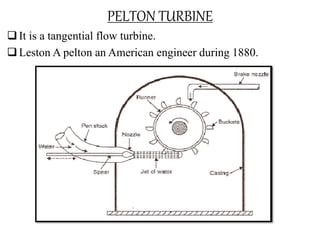
- 1. PELTON TURBINE It is a tangential flow turbine. Leston A pelton an American engineer during 1880.
- 2. It consists the following main parts; 1. Spear and nozzle 2. Runner with buckets 3. Brake nozzle 4. Outer casing 5. Governing mechanism 1. Spear and nozzle: In the downstream end of the penstock, with efficient nozzle which converts the whole hydraulic energy into kinetic energy. The nozzle will delivered high speed of water. To regulate the water of flow there is a spear arrangement. The spear can move forward or backward to increase or decrease the nozzle flow passage.
- 3. 2.Runner with buckets: It consists of circular disc with number of buckets spaced around the periphery. The runner is mounted on horizontal shaft with small thrust bearings. The buckets have a shape of the double semi-elliptical ridge(Splitter). The buckets have angle at outlet varies from 10o to 20o and the water deflected from 180o to 190o . The splitter which divides the jet into two equal portions. After the smooth inner surface of the bucket , water leaves as its outer edge.
- 4. 3.Outer casing: It made of cast iron or fabricated steel plates. There is no hydraulic function to perform. It is used to prevent the splashing of water and discharge to tailrace. It also act as a safeguard against accidents. 4.Brake nozzle: When a nozzle is closed by the moving spear in forward direction, the water striking on buckets gets zero. But the runner will revolve due to inertia. So to stop the runner there is a small nozzle(brake nozzle). It will produce a jet of water at the back of the buckets. This jet of water is called breaking jet. 5.Governing mechanism: It is used to regulate the water into the turbine at a constant level, so speed of turbine gets constant. It automatically regulates the quantity of water flowing through the runner with any variation of load.
- 5. FRANCIS TURBINE It is an inward flow reaction turbine. It is developed by American engineer James B.Francis In this the water enters the runner at its outer periphery and it leaves axially at its centre.
- 6. 1.Penstock: It is large sized conduit which conveys water from dam or anything to the runner. It has greater size than the pelton wheel. 2.Scroll or Spiral casing: The water from the penstock enters a scroll casing which completely surrounds the runner. The C/S area of scroll casing is maximum at inlet and almost zero at outlet. It will helps to maintain the constant velocity in the runner. The casing is made of cast steel, plate steel or concrete depending on the pressure to which it is subjected. 3.Speed ring or Stay ring: From scroll casing, the water passes through a speed ring or stay ring.
- 7. It consists of upper and lower rings held together by series of fixed vanes called stay vanes. The stay vanes are taken as half the number of guide vanes. Its function is to direct the water from a scroll casing to the guide vanes & also resists the load imposed on it. It may be made of cast iron or cast steel. 4.Guide vanes or wicket gates: From the speed ring, the water passes through a series of guide vanes. The gates are provided all around the periphery of turbine runner. It is used to regulate the water to the runner as per design. It is like a airfoil shape and may be made of cast steel or plate steel.
- 8. 5.Runner and runner blades: Runner is a circular wheel on which a series of radially curved vanes are fixed. This shape is used to enter the water at the outer periphery and it leaves axially at inner periphery. The runner made up of cast iron or stainless steel and they are keyed to shaft. The number of runner blades usually varies from 16 to 24. 6.Draft tube: The water after passing through the runner is discharged to the tailrace through a gradually expanding tube , i.e, draft tube.