7. Other standardized assessment methods
1. Root-Means-Square roughness (Rq or RMS)
• Closely related to the roughness average (Ra)
• Square the distances, average them, and determine the square root of the result
• The resulting value is the index for surface texture comparison
• Usually 11% higher than the Ra value
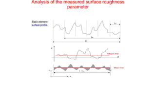
2. Maximum Peak-Valley Roughness (Rmax or Rt)
• Determine the distance between the lines that contact the extreme outer and inner point
of the profile
• Second most popular method in industry
• See figure A
3. Ten-Point Height (Rz)
• Averages the distance between the five peaks and five deepest valleys within the sampling
length
• See figure B
8. 4. Average Peak-to-Valley Roughness (R or H or Hpl)
• Average the individual peak-to-valley heights
• See figure C
• Use the height between adjacent peaks and valleys, not measure
from a center line to peak valleys
5. Average Spacing of Roughness Peaks (Ar or AR)
• Average the distance between the peaks without regard to their
height
• See figure D
6. Swedish Height of Irregularities (R or H)
• Also known as Profiljup methos
• Only standard in Sweden (H) and Denmark (R)
• It assume that, in wear situation, the peaks are affected by wear,
but the valleys are not.
9. 7. Bearing Length Ration (Tp and others)
• Create a reference line through some of the peaks
• This line is at a predetermined height from the mean line, and
you have then divide the subtended length through the peaks by
sampling length to arrive at the assessment value
• See figure F
8. Leveling Depth (Rp and others)
• Measure the height between the highest peak and the mean line
• See figure G
9. Waviness Height (W)
• Assess the waviness without regard to roughness by determining
the peak-to-valley distance of the total profile within the
sampling length
12. When two nominally flat surfaces are placed in contact, surface roughness causes contact
to occur at discrete contact spots (junctions), Figure . The sum of the areas of all the contact
spots constitutes the real (true) area of contact or simply contact area, and for most
materials with applied load, this will be only a small fraction of the apparent (nominal) area
of contact(that which would occur if the surfaces were perfectly smooth)
Schematic representation of an interface, showing the apparent and real areas of contact. Typical size
of an asperity contact is from submicron to a few microns. Inset shows the details of a contact on a
submicron scale.
13. Analysis of contacts
1. Single Asperity Contact of Homogeneous and Frictionless Solids
* Elastic contact
* Elastic-plastic contact of frictionless solid
2. Single Asperity Contact of Layered Solids in Frictionless and Frictional
Contacts
* Elastic contact
* Elastic-plastic contact
3. Multiple Asperity Dry Contacts