SlideShare a Scribd company logo
1 of 75
Download to read offline
DET NORSKE VERITAS AS
The electronic pdf version of this document found through http://www.dnv.com is the officially binding version
OFFSHORE STANDARD
DNV-OS-A101
Safety Principles
and Arrangements
JULY 2014
This document has been amended since the main edition (July 2014), most recently in October 2014.
See “Changes” on page 3.
© Det Norske Veritas AS July 2014
Any comments may be sent by e-mail to rules@dnv.com
This service document has been prepared based on available knowledge, technology and/or information at the time of issuance of this document, and is believed to reflect the best of
contemporary technology. The use of this document by others than DNV is at the user's sole risk. DNV does not accept any liability or responsibility for loss or damages resulting from
any use of this document.
FOREWORD
DNV is a global provider of knowledge for managing risk. Today, safe and responsible business conduct is both a license
to operate and a competitive advantage. Our core competence is to identify, assess, and advise on risk management. From
our leading position in certification, classification, verification, and training, we develop and apply standards and best
practices. This helps our customers safely and responsibly improve their business performance. DNV is an independent
organisation with dedicated risk professionals in more than 100 countries, with the purpose of safeguarding life, property
and the environment.
DNV service documents consist of among others the following types of documents:
— Service Specifications. Procedural requirements.
— Standards. Technical requirements.
— Recommended Practices. Guidance.
The Standards and Recommended Practices are offered within the following areas:
A) Qualification, Quality and Safety Methodology
B) Materials Technology
C) Structures
D) Systems
E) Special Facilities
F) Pipelines and Risers
G) Asset Operation
H) Marine Operations
J) Cleaner Energy
O) Subsea Systems
U) Unconventional Oil & Gas
DET NORSKE VERITAS AS
Amended October 2014 Offshore Standard DNV-OS-A101, July 2014
CHANGES – CURRENT – Page 3
CHANGES – CURRENT
General
This document supersedes DNV-OS-A101, October 2013.
Text affected by the main changes in this edition is highlighted in red colour. However, if the changes involve
Det Norske Veritas AS, company registration number 945 748 931, has on 27th November 2013 changed its
name to DNV GL AS. For further information, see www.dnvgl.com. Any reference in this document to
“Det Norske Veritas AS” or “DNV” shall therefore also be a reference to “DNV GL AS”.
a whole chapter, section or sub-section, normally only the title will be in red colour.
Amendments October 2014
• Ch.2
— Sec.5 [4] Unintended heading level change has been restored.
Main changes July 2014
• General
A new Ch.2 Sec.8 has been included describing specifically the requirements for floating storage units. Ch.2
Sec.7 applies now for floating production and storage units only.
In addition to the above stated main changes, editorial corrections may have been made.
Editorial corrections
DET NORSKE VERITAS AS
Amended October 2014 Offshore Standard DNV-OS-A101, July 2014
Contents – Page 4
CONTENTS
CHANGES – CURRENT................................................................................................................... 3
CH. 1 INTRODUCTION ......................................................................................... 8
Sec. 1 General................................................................................................................................. 8
1 General.......................................................................................................................................................8
1.1 Introduction......................................................................................................................................8
1.2 Objectives ........................................................................................................................................8
1.3 Scope................................................................................................................................................8
1.4 Application.......................................................................................................................................8
1.5 Structure...........................................................................................................................................9
2 Normative references................................................................................................................................9
2.1 General.............................................................................................................................................9
2.2 DNV offshore standards ..................................................................................................................9
2.3 DNV Recommended Practices ........................................................................................................9
2.4 Other references...............................................................................................................................9
3 Informative references............................................................................................................................10
4 Definitions ................................................................................................................................................10
4.1 Verbal forms ..................................................................................................................................10
4.2 Definitions......................................................................................................................................10
4.3 Abbreviations.................................................................................................................................13
CH. 2 TECHNICAL PROVISIONS..................................................................... 14
Sec. 1 Design principles and accidental loads ........................................................................... 14
1 Introduction.............................................................................................................................................14
1.1 Objective........................................................................................................................................14
1.2 Application.....................................................................................................................................14
2 Design principles .....................................................................................................................................14
2.1 Main principles ..............................................................................................................................14
2.2 Additional requirements.................................................................................................................14
2.3 Design for accidental loads............................................................................................................14
3 Generic design accidental loads .............................................................................................................15
3.1 General...........................................................................................................................................15
3.2 Dropped objects .............................................................................................................................15
3.3 Collision loads ...............................................................................................................................16
3.4 Unintended flooding ......................................................................................................................16
3.5 Loads caused by extreme weather .................................................................................................16
3.6 Explosion loads..............................................................................................................................16
3.7 Heat loads.......................................................................................................................................20
Sec. 2 Arrangement ..................................................................................................................... 21
1 Introduction.............................................................................................................................................21
1.1 Objective........................................................................................................................................21
1.2 Application.....................................................................................................................................21
2 General arrangement..............................................................................................................................21
2.1 Segregation of areas.......................................................................................................................21
2.2 Arrangement ..................................................................................................................................21
3 Location of plants and equipment .........................................................................................................22
3.1 Location of safety systems.............................................................................................................22
3.2 Location of air intakes and other openings....................................................................................22
3.3 Fired heaters, combustion engines and hot surfaces .....................................................................23
3.4 Location of flares and vents...........................................................................................................23
4 Dangerous goods and cranes..................................................................................................................23
4.1 Storage of dangerous goods ..........................................................................................................23
4.2 Cranes and lay down areas.............................................................................................................24
5 Other requirements.................................................................................................................................24
5.1 Asbestos.........................................................................................................................................24
5.2 Railings and barriers ......................................................................................................................24
DET NORSKE VERITAS AS
Amended October 2014 Offshore Standard DNV-OS-A101, July 2014
Contents – Page 5
Sec. 3 Hazardous area classification .......................................................................................... 25
1 Introduction.............................................................................................................................................25
1.1 Objective and scope .......................................................................................................................25
1.2 Application.....................................................................................................................................25
2 Basic principles........................................................................................................................................25
2.1 Definition of hazardous areas ........................................................................................................25
2.2 Hazardous fluids (sources).............................................................................................................26
2.3 General principles for area classification.......................................................................................26
2.4 Extent of the hazardous zone .........................................................................................................26
3 Openings, access and ventilation conditions.........................................................................................26
3.1 General...........................................................................................................................................26
3.2 Openings and access ......................................................................................................................27
3.3 General requirements for mechanical ventilation systems ............................................................28
3.4 Ventilation conditions for overpressure protection of enclosed spaces.........................................28
3.5 Dilution ventilation........................................................................................................................29
3.6 Ventilation of battery compartments .............................................................................................29
4 Electrical installations in hazardous areas............................................................................................29
4.1 Principle requirement.....................................................................................................................29
4.2 General requirements.....................................................................................................................29
Sec. 4 Emergency shutdown (ESD)............................................................................................ 30
1 Introduction.............................................................................................................................................30
1.1 Objective and scope .......................................................................................................................30
1.2 Application.....................................................................................................................................30
1.3 Definition.......................................................................................................................................30
2 Generic requirements .............................................................................................................................30
2.1 General...........................................................................................................................................30
Sec. 5 Escape and communication.............................................................................................. 34
1 General.....................................................................................................................................................34
1.1 Objectives ......................................................................................................................................34
1.2 Application.....................................................................................................................................34
2 Escape routes ...........................................................................................................................................34
2.1 Principles........................................................................................................................................34
2.2 Sizing .............................................................................................................................................34
2.3 Walkways, stairs, ladders and lifts.................................................................................................35
2.4 Escape from machinery spaces category A ...................................................................................35
2.5 Helicopter decks.............................................................................................................................35
3 Muster areas and lighting.......................................................................................................................35
3.1 Muster areas...................................................................................................................................35
4 Emergency lighting .................................................................................................................................36
4.1 Specific requirement .....................................................................................................................36
5 Marking and warning signboards .........................................................................................................36
5.1 General...........................................................................................................................................36
5.2 Safety plans and warning signboards.............................................................................................36
6 Communications and alarms..................................................................................................................37
6.1 Introduction....................................................................................................................................37
6.2 General requirements.....................................................................................................................37
Sec. 6 Special provisions for drilling and/or well intervention units ...................................... 39
1 Introduction.............................................................................................................................................39
2 Arrangement............................................................................................................................................39
2.1 General...........................................................................................................................................39
2.2 Mooring systems............................................................................................................................39
2.3 Moonpools .....................................................................................................................................39
2.4 Production and well testing............................................................................................................39
2.5 Control station................................................................................................................................39
3 Hazardous area classification.................................................................................................................40
3.1 General...........................................................................................................................................40
3.2 Drilling plant/well intervention plant.............................................................................................40
3.3 Electrical installations in hazardous areas .....................................................................................41
4 Emergency shutdown (ESD) ..................................................................................................................41
4.1 Introduction....................................................................................................................................41
4.2 Basic provisions.............................................................................................................................41
DET NORSKE VERITAS AS
Amended October 2014 Offshore Standard DNV-OS-A101, July 2014
Contents – Page 6
4.3 Enhanced ESD ...............................................................................................................................42
5 Escape, evacuation and communications..............................................................................................46
5.1 General...........................................................................................................................................46
5.2 Alarm .............................................................................................................................................46
Sec. 7 Special provisions for floating production and storage units ....................................... 47
1 Introduction.............................................................................................................................................47
2 Arrangement............................................................................................................................................47
2.1 General...........................................................................................................................................47
2.2 Process/utility and storage tank decks ...........................................................................................47
2.3 Risers and piping............................................................................................................................47
2.4 Entrances and openings..................................................................................................................48
2.5 Crude oil storage area and cofferdams...........................................................................................48
2.6 Slop tanks.......................................................................................................................................49
2.7 Crude oil pump rooms and pipe tunnels ........................................................................................49
2.8 Mooring systems............................................................................................................................49
3 Hazardous area classification.................................................................................................................49
3.1 General...........................................................................................................................................49
3.2 Product storage tank areas .............................................................................................................49
3.3 Equipment and cables in hazardous areas......................................................................................50
4 Emergency shutdown (ESD) principles.................................................................................................50
4.1 General requirements.....................................................................................................................50
4.2 Safety and shutdown philosophy ...................................................................................................50
4.3 Fail-safe functionality....................................................................................................................50
4.4 Shutdown logic ..............................................................................................................................51
4.5 Automatic and manual shutdown...................................................................................................52
4.6 Additional provisions.....................................................................................................................52
5 Inert and vent systems for cargo tanks ................................................................................................55
5.1 General...........................................................................................................................................55
5.2 Over- /under – pressure protection of cargo tanks.........................................................................55
5.3 Protection against explosive atmospheres ....................................................................................55
5.4 Protection of personnel during tank entry......................................................................................56
Sec. 8 Special provisions for floating storage units................................................................... 57
1 Introduction.............................................................................................................................................57
2 Arrangement............................................................................................................................................57
2.1 General...........................................................................................................................................57
2.2 Cargo area......................................................................................................................................57
2.3 Piping.............................................................................................................................................57
2.4 Entrances and openings..................................................................................................................58
2.5 Crude oil storage area and cofferdams...........................................................................................58
2.6 Slop tanks.......................................................................................................................................58
2.7 Crude oil pump rooms and pipe tunnels ........................................................................................58
2.8 Mooring systems............................................................................................................................58
3 Hazardous area classification.................................................................................................................58
4 Emergency shutdown (ESD) principles.................................................................................................58
4.1 General requirements.....................................................................................................................58
4.2 Safety and shutdown philosophy ...................................................................................................59
4.3 Fail-safe functionality....................................................................................................................59
4.4 Shutdown logic for units with HC blanketing ...............................................................................59
4.5 Automatic and manual shutdown...................................................................................................60
4.6 Additional provisions.....................................................................................................................60
5 Inert and vent systems for cargo tanks ................................................................................................60
Sec. 9 Special provisions for liquefied natural gas import and export terminals and
production units................................................................................................................ 61
1 General.....................................................................................................................................................61
2 Risk assessment .......................................................................................................................................61
2.1 General...........................................................................................................................................61
2.2 Hazards ..........................................................................................................................................61
3 Arrangement............................................................................................................................................61
3.1 General...........................................................................................................................................61
3.2 Location of equipment...................................................................................................................62
3.3 Location of risers and ESD valves.................................................................................................62
3.4 Location of storage tanks...............................................................................................................62
3.5 Piping.............................................................................................................................................62
DET NORSKE VERITAS AS
Amended October 2014 Offshore Standard DNV-OS-A101, July 2014
Contents – Page 7
3.6 Mooring of floating installations ...................................................................................................63
4 Hazardous area classification.................................................................................................................63
4.1 Codes and standards.......................................................................................................................63
4.2 Entrances and openings..................................................................................................................63
5 Systems.....................................................................................................................................................63
5.1 Emergency shutdown (ESD) .........................................................................................................63
5.2 Escape routes .................................................................................................................................64
5.3 Cargo, inert and vent systems for units with in-service inspections..............................................64
CH. 3 CLASSIFICATION AND CERTIFICATION ......................................... 65
Sec. 1 Classification ..................................................................................................................... 65
1 General.....................................................................................................................................................65
1.1 Introduction....................................................................................................................................65
1.2 Applicable requirements................................................................................................................65
1.3 Application.....................................................................................................................................65
1.4 Documentation...............................................................................................................................65
Sec. 2 Certification ...................................................................................................................... 66
1 Equipment categorisation.......................................................................................................................66
1.1 Principle requirement.....................................................................................................................66
1.2 Categories ......................................................................................................................................66
2 Certification requirements .....................................................................................................................67
App. A Categorisation of sources of release ................................................................................ 68
A.1 General ..................................................................................................................................................... 68
A.2 Continuous sources of release.................................................................................................................. 68
A.3 Primary sources of release........................................................................................................................ 68
A.4 Secondary sources of release.................................................................................................................... 68
App. B Formal safety assessment................................................................................................. 69
B.1 Safety assessment..................................................................................................................................... 69
B.2 Alternative requirements.......................................................................................................................... 72
App. C Guideline for ignition source control working methodology........................................ 73
C.1 General ..................................................................................................................................................... 73
CHANGES – HISTORIC ................................................................................................................. 74
DET NORSKE VERITAS AS
Amended October 2014 Offshore Standard DNV-OS-A101, July 2014
Ch.1 Sec.1 General – Page 8
CHAPTER 1 INTRODUCTION
SECTION 1 GENERAL
1 General
1.1 Introduction
This standard provides general safety and arrangement principles for mobile units and offshore installations.
1.2 Objectives
The objectives of the standard are to:
— provide an internationally acceptable standard of safety for offshore units and installations by defining
requirements for design loads, arrangements, area classification, shut down logic, alarms, escape ways and
communication
— serve as a contractual reference document between suppliers and purchasers
— serve as a guideline for designers, suppliers, purchasers and regulators
— specify procedures and requirements for units or installations subject to DNV certification and
classification services.
1.3 Scope
1.3.1 The scope of this standard covers the following technical topics
— Design principles and accidental loads.
— Area arrangement.
— Hazardous area classification.
— Emergency Shutdown (ESD) principles and requirements.
— Escape and communication.
1.3.2 The standard does not cover the location and arrangement of helicopter decks.
Guidance note:
Relevant requirements for helicopter decks are given in MODU Code Ch.13 referring in its turn to publications from
the International Civil Air Organisation (ICAO).
---e-n-d---of---G-u-i-d-a-n-c-e---n-o-t-e---
1.3.3 This standard is applicable for all types of mobile offshore units and offshore installations.
1.3.4 The standard has been developed for general world-wide application. Governmental legislation may
include requirements in excess of the provisions of this standard depending on type, location and intended
service of the unit or installation.
1.4 Application
1.4.1 Interpretations
This standard has been based on internationally accepted principal requirements, defined in the normative
references as listed in [2]. In cases where these a) contain only functional requirements, b) allow alternative
solutions to prescriptive requirements or c) are generally or vaguely worded, a DNV interpretation has been
added.
1.4.2 The interpretations are not aiming at introducing additional requirements but at achieving uniform
application of the principal requirements. The interpretations can be regarded as norms for fulfilling the
principle requirements.
1.4.3 The interpretations do not preclude the use of other alternative solutions. Such solutions shall be
documented and approved for compliance to the principal requirement equivalent to the original interpretation.
1.4.4 Classification
For use of this standard as technical basis for offshore classification as well as description of principles,
procedures, and applicable class notations related to classification services, see Table 1-1.
DET NORSKE VERITAS AS
Amended October 2014 Offshore Standard DNV-OS-A101, July 2014
Ch.1 Sec.1 General – Page 9
1.4.5 The scope of classification may be extended by the voluntary notation ES. The applicable sections or
requirements as indicated accordingly shall only be enforced in case this notation is part of this extended
classification scope (see also, Ch.3 Sec.1 [1.2]). The relevant requirements are identified by inclusion of ‘ES’
in the head line.
1.5 Structure
This standard is divided into three chapters:
— Ch.1: General introduction, scope, definitions and references.
— Ch.2: Technical provisions for safety principles and arrangement for systems applicable to all types of
offshore units and installations in Sec.1 to Sec.5, followed by supplementary requirements for:
— Drilling Units and Well Intervention Units with return of hydrocarbon fluids (Sec.6)
— Floating Production and Storage Units (Sec.7)
— Floating Storage Units (Sec.8)
— LNG Import and Export Terminals and Production Units (Sec.9)
— Ch.3: Describing this use of this standard for classification purposes.
2 Normative references
2.1 General
2.1.1 The following standards include requirements that through reference in the text constitute provisions of
this offshore standard. Latest issue of the references shall be used unless otherwise agreed. Other recognised
standards may be used provided it can be demonstrated that these meet or exceed the requirements of the
standards referenced in [2.2] to [2.4].
2.1.2 Any deviations, exceptions and modifications to the codes and standards shall be documented and agreed
between the supplier, purchaser and verifier, as applicable.
2.2 DNV offshore standards
The latest revision of the DNV Offshore Standards listed in Table 1-2 applies.
2.3 DNV Recommended Practices
The latest revision of the DNV Recommended Practices listed in Table 1-3 applies.
2.4 Other references
The latest revision of the documents listed in Table 1-4 applies.
Table 1-1 DNV Offshore Service Specifications
Reference Title
DNV-OSS-101 Rules for Classification of Offshore Drilling and Support Units
DNV-OSS-102 Rules for Classification of Floating Production, Storage and Loading Units
DNV-OSS-103 Rules for Classification of LNG/LPG Floating Production and Storage Units or Installations
DNV-OSS-104 Rules for Classification of Self-elevating drilling units
Table 1-2 DNV offshore standards
Reference Title
DNV-OS-C301 Stability and Watertight Integrity
DNV-OS-D101 Marine and Machinery Systems and Equipment
DNV-OS-D201 Electrical Installations
DNV-OS-D202 Automation, Safety, and Telecommunication Systems
DNV-OS-D301 Fire Protection
Table 1-3 DNV recommended practices
Reference Title
DNV-RP-A201 Plan Approval Documentation Types – Definitions
Table 1-4 Other references
Reference Title
DNV DNV Rules for Classification of Ships (Rules for Ships)
DET NORSKE VERITAS AS
Amended October 2014 Offshore Standard DNV-OS-A101, July 2014
Ch.1 Sec.1 General – Page 10
3 Informative references
The codes and standards in Table 1-5 are referenced in the text of this offshore standard, and may be used as a
source of supplementary information. If not otherwise stated, the latest revision of the documents applies.
4 Definitions
4.1 Verbal forms
4.2 Definitions
4.2.1 Accommodation area: Space used for cabins, offices, lavatories, corridors, hospitals, cinemas, public
spaces etc. Service spaces and control stations may be included within the accommodation area.
4.2.2 Product storage area: Part of a unit or installation which contains: the storage spaces, the pump rooms
and/or cofferdams adjacent to product storage tanks, and includes deck areas over the full beam and length of
spaces above. See also Tank deck.
4.2.3 Control station or Control room: General term for any location space where essential control functions
are performed during transit, normal operations or emergency conditions. Typical examples are central control
room, radio room, process control room, bridge, emergency response room etc. For the purpose of compliance
with the SOLAS Convention and the MODU Code, the emergency generator room, UPS rooms and fire pump
rooms are defined as control stations.
Table 1-5 Informative references
Reference Title
API RP 14C Analysis, Design, Installation and Testing of Basic Surface Safety Systems for Offshore
Production Platforms
ISO 10418 Petroleum and natural gas industries - Offshore production platforms - Analysis, design,
installation and testing of basic surface safety systems
API RP 14J Recommended Practice for Design and Hazard Analysis for Offshore Production Facilities
API RP 505 Recommended Practice for Classification of Locations for Electrical Installations at Petroleum
Facilities Classified as Class I, Zone 0, Zone 1, and Zone 2
API Std 521/ISO 23251 Pressure-relieving and Depressuring Systems
COLREG Convention on the International Regulations for Preventing of Collisions at Sea,
DNV-OS-E101 Drilling Plant
DNV-OS-E201 Oil and Gas Processing Systems
DNV Technical Report
99-3139
Guidelines for Risk and Emergency Preparedness Assessment: MODU (ss), drill ships, well
intervention ships and well intervention units (ss)
EN 1834, Part 1-3 Reciprocating internal combustion engines - Safety requirements for design and construction
of engines for use in potentially explosive atmospheres
EN 1473 Installation and Equipment for Liquefied natural gas. Design of onshore installations
ICAO Convention on international civil aviation: annex 14 aerodromes. Volume II. Heliports
IEC 60079-10-1 Electrical apparatus for explosive gas atmospheres - Part 10: Classification of hazardous areas
IEC 61892-7 Mobile and fixed offshore units - Electrical installations - Part 7: Hazardous area
IGC Code International Code for the Construction and Equipment of Ships carrying Liquefied Gas in Bulk
MODU Code Code for the Construction and Equipment of Mobile Offshore Drilling Units,
IMO Res. A.1021(26) Code on Alerts and Indicators
Energy Institute: Model
Code of Safe Practice
Part 15
Area Classification Code for Installations Handling Flammable Fluids
ISO 13702 Petroleum and natural gas industries - Control and mitigation of fires and explosions on
offshore production installations - Requirements and guidelines
NFPA 59 A Standard for Production, Storage and handling of Liquefied Natural Gas
SOLAS International Convention for the Safety of Life at Sea
Table 1-6 Verbal forms
Term Definition
Shall: Verbal form used to indicate requirements strictly to be followed in order to conform to the document.
Should: Verbal form used to indicate that among several possibilities one is recommended as particularly suitable,
without mentioning or excluding others, or that a certain course of action is preferred but not necessarily required.
May: Verbal form used to indicate a course of action permissible within the limits of the document.
DET NORSKE VERITAS AS
Amended October 2014 Offshore Standard DNV-OS-A101, July 2014
Ch.1 Sec.1 General – Page 11
4.2.4 Design accidental events: Events which could cause death or serious personal injury to personnel on
board the unit or installation, and which are controlled in order to meet risk acceptance criteria. This includes
events, which could result in significant damage to the structure of the unit or installation, loss of stability, or
the need to evacuate. Design accidental events form one basis for design dimensioning accidental loads.
4.2.5 Design accidental loads: Loads or actions resulting from a defined accidental effect. These loads are
included in the basis for design of a system or a structure.
4.2.6 Dimensioning accidental loads: Loads that are calculated to meet the acceptance criteria.
4.2.7 Drilling area: Includes the derrick, drill floor, BOP area and the area containing shale shakers and
degassers. See utility area for drilling utilities such as mud mixing, pumping, bulk storage and cementing.
4.2.8 Essential services: Generally defined as a service which needs to be, in continuous operation for
maintaining the unit’s manoeuvrability (if applicable), or whose loss or failure would create an immediate
danger to the unit.
4.2.9 Embarkation area: Area immediately adjacent to a transport means of escape or evacuation which is
designated for personnel awaiting the instruction leave or abandon the unit or installation.
4.2.10 Emergency response: Action to safeguard the health and safety of persons on or near the unit or
installation. This usually includes all actions through alarm, escape, muster, communications and control,
evacuation and rescue.
4.2.11 Enclosed space: Space bounded by floors, bulkhead and/or decks that may have doors, windows or
other similar openings.
4.2.12 Escape: Means for leaving the various workplaces on the unit or installation leading to a safe place and
without directly entering the sea.
4.2.13 Evacuation: Means for leaving the unit or installation and moving away from the vicinity in an
emergency in a systematic manner.
Hazardous areas: All areas in which a flammable or explosive gas and air mixtures is, or may normally be
expected to be, present in quantities such as to require special precautions for the construction and use of
electrical equipment and machinery.
4.2.14 Ignition source: Any object in relation to area classification and safety philosophy that could ignite an
explosive gas and air atmosphere. Typical sources could be uncertified electrical apparatus, naked flame,
sparks, static discharges, hot surfaces above ignition temperature etc.
4.2.15 Important for safety: Areas, systems and functions, which are provided to prevent, detect, control and
mitigate the effects of an accidental event.
4.2.16 Important services: Generally defined as a service which needs not necessarily be in continuous operation
but whose failure or non-availability would not create an immediate danger but impairs the unit’s safety.
Guidance note:
Systems and equipment providing the service above are essential respectively important. This applies also to systems
and equipment supporting these like control and electrical systems.
---e-n-d---of---G-u-i-d-a-n-c-e---n-o-t-e---
4.2.17 Integrity: Ability of the unit or installation to remain safe and stable to safeguard personnel and
facilities on board. Integrity is generally taken to mean structural soundness, strength, stability and buoyancy
required to fulfil these actions.
4.2.18 LNG export terminal: An offshore terminal which processes hydrocarbons and refrigerates gas to
produce LNG.
4.2.19 LNG import terminal: An offshore terminal which receives and regasifies LNG to provide gas to the
market gas grid.
4.2.20 Machinery space: Machinery spaces of category A and other spaces containing propulsion machinery,
boilers, oil fuel units, steam and internal combustion engines, generators and major electrical machinery, oil
filling stations, refrigerating, stabilising, ventilation and air conditioning machinery and similar spaces and
trunks to such spaces.
(Ref. SOLAS Reg. II-2/3.30, MODU Code 1.3.33).
4.2.21 Machinery spaces of category A: Spaces and trunks to such spaces which contain:
— internal combustion machinery used for main propulsion; or
DET NORSKE VERITAS AS
Amended October 2014 Offshore Standard DNV-OS-A101, July 2014
Ch.1 Sec.1 General – Page 12
— internal combustion machinery used for purposes other than main propulsion where such machinery has in
the aggregate a total power output of not less than 375 kW, or
— any oil-fired boiler or oil fuel unit.
Spaces which contain oil fired equipment other than boilers, such as inert gas generators, incinerators, waste
disposal units etc., shall be considered as machinery spaces of category A.
(Ref. SOLAS Reg. II-2/3.31, MODU Code 1.3.34 and IACS UR F35)
4.2.22 Major hazards: Hazards that may result in fire, explosion, loss of life, damage to the unit or installation
or safety systems, or impaired escape or evacuation.
4.2.23 Mobile unit: A buoyant construction engaged in offshore operations including drilling, production,
storage or support functions, not intended for service at one particular offshore site and which can be relocated
without major dismantling or modification.
Guidance note:
The following is the definition in the MODU Code: Mobile offshore drilling unit (MODU) or unit is a vessel capable
of engaging in drilling operations for the exploration for or exploitation of resources beneath the sea-bed such as liquid
or gaseous hydrocarbons, sulphur or salt (Ref. MODU Code 1.3.40).
---e-n-d---of---G-u-i-d-a-n-c-e---n-o-t-e---
4.2.24 Muster area: A designated area where personnel gather for protection, instructions and final
preparations before evacuation. A muster area shall be protected from the immediate effects of an emergency,
and the primary muster area is normally within the temporary refuge.
4.2.25 Offshore installation: A buoyant or non-buoyant construction engaged in offshore operations including
drilling, production, storage or support functions, and which is designed and intended for use at a location for
an extended period. This will also include Floating LNG terminals.
4.2.26 Performance standard: Quantitative or qualitative definition of the functionality required of a system
or item of equipment. It relates to the purpose and performance of the system or item and can be expressed in
terms of capacity, functionality, reliability, availability, survivability etc.
4.2.27 Prevailing wind: Wind direction, which has the highest probability of occurrence.
4.2.28 Processing area: Area designated for separation, compression, treatment and disposal of reservoir fluids.
4.2.29 Riser area: Area containing import and/or exports risers and includes the isolation valve on the riser.
See also Turret area.
4.2.30 Safety assessment: Systematic evaluation of safety involving identification and evaluation of hazards
and events that could result in loss of life, property damage, environmental damage, or the need to evacuate.
4.2.31 Safety criteria: Qualitative and quantitative criteria, which express the maximum tolerable risk to
personnel, environment, safety functions etc.
4.2.32 Safety systems: Systems, including required utilities, which are provided to prevent, detect/ warn of an
accidental event/abnormal conditions and/or mitigate its effects.
Interpretation:
1) The following should be considered as safety systems:
— ESD, including blowdown where relevant
— PSD
— Fire & gas detection
— PA/GA
— Fire-fighting systems
— BOP incl. control system
— Safety systems for essential or important services
2) Safety systems are normally considered as “on-demand” functions.
––––––––––––––– end of Interpretation –––––––––––––––
4.2.33 Semi-enclosed location: Locations where natural conditions of ventilation are notably different from
those on open decks due to the presence of structures such as roofs, windbreaks and bulkheads and which are
so arranged that dispersion of gas may be hindered.
4.2.34 Tank deck: Deck, or part of a deck, which forms the top of a product storage tank.
DET NORSKE VERITAS AS
Amended October 2014 Offshore Standard DNV-OS-A101, July 2014
Ch.1 Sec.1 General – Page 13
4.2.35 Temporary refuge or shelter area: Area provided to protect personnel from the effects of an emergency,
which is beyond immediate control. Protection shall be sufficient to allow controlled muster, emergency
assessment, incident evaluation, and implementation of control emergency procedures, and evacuation etc. The
temporary refuge should be provided with adequate command communication facilities to address an
emergency and organise safe evacuation if necessary.
4.2.36 Turret area: Area containing mooring equipment, which enables the unit to rotate relative to fixed
facilities or pipelines on the seabed. Import and export risers are usually located within the turret area.
4.2.37 Utility areas: Areas for combustion equipment, power generation, switchboards, boiler, water injection
facilities, workshops, storage areas, drilling utilities and general machinery. A utility area should not include
production, drilling or wellhead equipment, and will not normally include release sources leading to
designation as a significant hazardous area.
4.3 Abbreviations
The abbreviations in Table 1-7 are used.
Table 1-7 Abbreviations
Abbreviation In full
ALS Accidental limit states
API American Petroleum Institute
AVS Abandon vessel shutdown
BOP Blow out preventer
CCR Centralised control room
CFD Computational flow dynamics
DAL Design accidental load
DP Dynamic Positioning
ESD Emergency shutdown
FMEA Failure mode and effect analysis
HAZID Hazard identification
HAZOP Hazard and operability (study)
IACS International Association of Classification Societies
IACS UI Unified interpretation
IACS UR Unified requirement
ICAO International Civil Aviation Organisation
IEC International Electrotechnical Commission
IMO International Maritime Organization
ISO International Organisation of Standardisation
KO Knock out
LEL Lower explosion limit
LER Local Equipment Room
LIR Local Instrument Room
LNG Liquefied Natural Gas
MAC Manually activated call point
MJ Mega Joules
MODU Mobile Offshore Drilling Unit
NDE Normally de-energised
NE Normally energised
OS Offshore standard
PA/GA Public address/general alarm
PSD Process shutdown
RP Recommended practice
SCSSSV Surface controlled subsea shutdown valve
SSIV Sub-surface isolation valve
STL Submerged turret loading
STP Submerged turret production
UEL Upper explosion limit
ULS Ultimate limit states
UPS Uninterruptible power supply
DET NORSKE VERITAS AS
Amended October 2014 Offshore Standard DNV-OS-A101, July 2014
Ch.2 Sec.1 Design principles and accidental loads – Page 14
CHAPTER 2 TECHNICAL PROVISIONS
SECTION 1 DESIGN PRINCIPLES AND ACCIDENTAL LOADS
1 Introduction
1.1 Objective
Application of these design principles is intended to establish an acceptable level of safety, whilst promoting
safety improvements through experience and available technology.
1.2 Application
The principles and requirements shall be applied throughout the project lifecycle, beginning in the concept
phase, and reviewed and updated through detailed design and construction. The principles shall also be applied
with respect to subsequent modifications.
2 Design principles
2.1 Main principles
2.1.1 The following general principles shall be applied throughout the concept and design phases of the mobile
the unit or offshore installation.
2.1.2 The mobile unit or offshore installation shall be designed and constructed with sufficient integrity to
withstand operational and environmental loading throughout its lifecycle.
(Ref. MODU code 2.3)
2.1.3 Systems and structures shall be designed with suitable functionality and survivability for prevention of,
or protection from, design accident events affecting the unit or installation. For structures see also DNV-RP-
C204 Design Against Accidental Loads.
Guidance note:
Definitions of accidental loads are typically given as follow:
- Design Accidental Loads are loads that are actually applied in the design
- Dimensioning Accidental Loads are calculated loads that meet the acceptance criteria.
The difference between the Design and the Dimensioning loads is a safety margin as long as the Design load is higher
than the Dimensioning load. A lower Design load is not acceptable.
---e-n-d---of---G-u-i-d-a-n-c-e---n-o-t-e---
2.1.4 Effective escape, shelter and evacuation facilities shall be provided to safeguard all personnel, as far as
practicable, at all times when the unit or installation is manned.
2.1.5 The generic Design Accidental Loads in [3] can be used for standard, conventional designs. If these loads
are too large for practical use, more refined analyses such as CFD analyses for fire and explosion loads, and
probabilistic risk analyses may be carried out in order to set the DALs.
2.1.6 For complex or non-standard applications a more comprehensive safety assessment shall be carried out.
App.B provides further information.
2.2 Additional requirements
In meeting the main design principles in [1], the following requirements shall be applied:
a) The design shall be sufficiently robust to tolerate at least one failure or operator error without resulting in
a major hazard, or damage to the unit or installation.
b) Suitable measures shall be provided to enable timely detection, control and mitigation of hazards.
c) Escalation to plant and areas that are not affected by the initiating event shall be avoided.
2.3 Design for accidental loads
2.3.1 The provisions given in [3] and [3] are based on international practice, experience with offshore designs
and results obtained by various risk assessments carried out on offshore units. For relatively standardised
designs (e.g. typical drilling units) the prescriptive requirements given in these standards are intended to
anticipate the most likely hazards which may be encountered.
DET NORSKE VERITAS AS
Amended October 2014 Offshore Standard DNV-OS-A101, July 2014
Ch.2 Sec.1 Design principles and accidental loads – Page 15
2.3.2 Each project shall, however, consider the applicability of the generic load approach used in [3] with
respect to the intended application and operation in order to identify, where applicable, hazards associated with
non-standard design or application.
Guidance note:
For example generic collision load is based on a supply vessel size of 5000 tons. In applications where supply vessels
are of much larger size this will need to be accounted for in defining the collision load.
---e-n-d---of---G-u-i-d-a-n-c-e---n-o-t-e---
2.3.3 The acceptance criteria shall be established prior to carrying out the safety assessment. The level of
acceptance criteria shall follow normal industry practice, see App.B.
Guidance note:
One example of normal industry practice: The Offshore Technology Report 2001/63 Marine Risk Assessment issued
by Health & Safety Executive (HSE) in UK.
---e-n-d---of---G-u-i-d-a-n-c-e---n-o-t-e---
3 Generic design accidental loads
3.1 General
3.1.1 The prescriptive requirements given here and elsewhere in DNV offshore standards are intended to take
account of accidental events which have been identified through previous risk studies and through experience.
3.1.2 The requirements are based on consideration of the integrity of the following main safety functions:
— integrity of shelter areas
— integrity of main fire and explosion dividers (fire and blast walls, decks, safety gaps, etc.)
— usability of escape ways
— usability of means of evacuation
— global load bearing capacity.
3.1.3 The selection of relevant design accidental loads is dependent on a safety philosophy considered to give
a satisfactory level of safety. The generic loads defined here represent the level of safety considered acceptable
by DNV, and are generally based on accidental loads affecting safety functions which have an individual (per
load type) frequency of occurrence in the order of 10-4 per year. This will normally correspond to an overall
frequency of 5 × 10⁻⁴ per year as the impairment frequency limit.
3.1.4 The most relevant design accidental loads are considered to be:
— impact loads, including dropped object loads and collision loads
— unintended flooding
— loads caused by extreme weather
— explosion loads
— heat loads from fires.
3.1.5 This standard is intended to address the above design accidental loads. Other additional relevant loads
that may be identified for a specific design or application will need to be separately addressed.
3.2 Dropped objects
3.2.1 It is assumed that lifting arrangements comply with Sec.2 [4.2] with regard to location of cranes and lay
down areas and with respect to lifting operations over pressurised equipment.
3.2.2 It is assumed that critical areas are designed for dropped object loads as defined in [3.2.3] and [3.2.4].
Guidance note:
Typical critical areas normally include: accommodation, workshops, storage areas for pressurised gas, areas with
hydrocarbon equipment.
---e-n-d---of---G-u-i-d-a-n-c-e---n-o-t-e---
3.2.3 The weights of the dropped objects to be considered for design of the structure are normally taken as the
operational hook loads in cranes.
3.2.4 The impact energy is normally not to be less than:
E =
M = mass of object (tonnes)
M g0 h (kJ)⋅ ⋅
DET NORSKE VERITAS AS
Amended October 2014 Offshore Standard DNV-OS-A101, July 2014
Ch.2 Sec.1 Design principles and accidental loads – Page 16
Interpretation:
The impact energy at sea level should normally not be taken less than 5 MJ for cranes with maximum capacity
more than 30 tonnes. The impact energy below sea level is assumed to be equal to the energy at sea level.
––––––––––––––– end of Interpretation –––––––––––––––
3.3 Collision loads
3.3.1 The impact energy to be considered is to be based on typical size of supply vessels in the area of operation
and normally not to be less than:
— 14 MJ (Mega Joule) for sideways collision
— 11 MJ for bow or stern collision
corresponding to a supply vessel of 5000 tonnes displacement with impact speed v = 2 m/s.
3.3.2 For vessels the impact energy is given as:
3.3.3 It is assumed that the unit or installation is not operating in a shipping lane. In such case a more detailed
assessment of relevant collision loads shall be carried out.
3.3.4 Where a unit is operating in tandem with a shuttle tanker, special precautions shall be taken to minimise
possibility of collision, or the design is to take account of collision loads.
3.4 Unintended flooding
3.4.1 The design sea pressure on watertight subdivisions (bulkheads and decks with compartment flooded)
shall for accidental damaged condition be taken as:
3.5 Loads caused by extreme weather
3.5.1 Characteristic values of individual environmental loads are defined by an annual probability of
exceedance equal to 10-2 (for Ultimate limit states, ULS) and 10-4 (for Accidental limit states, ALS).
3.6 Explosion loads
3.6.1 Requirements given in this standard are applicable to hydrocarbon gases. Where hydrogen, ethylene or
acetylene is used in large quantities special consideration shall be given to explosion loads.
Guidance note:
The overpressure values quoted in this section are based on studies with ethane, propane, butane, condensate and
crude oil vapour. Methane or evaporated LNG values may be slightly lower.
---e-n-d---of---G-u-i-d-a-n-c-e---n-o-t-e---
3.6.2 The recommended design process is to first evaluate and document all possibilities to make a safe design,
and then second to set DAL loads accordingly. The overall approach to set explosion DAL is here split in the
following sequence:
a) Evaluate and document the overall platform lay-out to minimize explosion and fire loads. Both distance to
living quarters and evacuation means, and to provide good ventilation and venting of the hazardous areas
shall be considered.
g0 = 9.81 m/s2
H = drop height in air (m)
M = displacement of vessel (t)
a = added mass of vessel, normally assumed as 0.4 M for sideways collision and 0.1 M for bow or stern
collision
v = impact speed (m/s).
hb = vertical distance in m from the load point to the damaged waterline.
E
1
2
--- M a+( )v
2
(kJ)=
pd 10 hb (kN/m
2
)⋅=
DET NORSKE VERITAS AS
Amended October 2014 Offshore Standard DNV-OS-A101, July 2014
Ch.2 Sec.1 Design principles and accidental loads – Page 17
b) Evaluate and document protection strategies such as ventilation strategy, safety gaps and fire and blast
dividers, grated and plated decks, and active mitigating measures such as flare, and shutdown and
blowdown philosophies. At this point the different fire and explosion areas are defined.
c) Decide the explosion areas and calculate their volumes (called the explosion volume). Explosion area is
defined in the guidance note below.
d) Find the curve letter in Table 1-1 based on congestion, operation, confinement and wind protection.
e) Read off the DAL pressure in Figure 1-1 using the explosion volume.
f) If the explosion volume is larger than 30 000 m3, the present DAL assessment is not applicable, and a
detailed analysis must be performed, or the size of the explosion area must be reduced.
g) The pressure pulse duration varies between 0.05 and 0.2 s. The higher and lower DAL pressures have a
shorter and longer duration within this range, respectively.
h) Drag DAL can be set to 1/3 of the pressure DAL.
Interpretation:
An explosion area is defined as an area where there is congestion and where a gas cloud can freely build
up. The borders are solid walls, solid decks and border between the congested area and open air. The
following conditions should be used to calculate the limiting borders of the explosion area. When the
borders are decided, the volume, called the explosion volume should be calculated.
- The distance to the next well congested area should be more than 20 m in order to classify as a separate
explosion area.
- Walls and decks that border to the neighbouring explosion area should be gas tight to a degree that is
reasonable. Small openings like pipe penetrations that are not sealed and other small penetrations are
acceptable as long as the total percentage opening area is less than 5% of the total area of the wall or deck.
- Decks that are solid, but not explosion and fire rated, can still be regarded as a border to the explosion
area. The fire area can hence be larger than the explosion area.
- The border/limit where the process area borders open air (either to the side or up) should be the natural
border where no more piping and equipment are placed. It is accepted that limited/open support structure
and railing is outside this border. For the height of the explosion area where the process equipment
heights varies largely along the area, an average height which has the same volume of open air below as
the volume of congested piping and equipment above, should be used.
- The upper border in a drill deck area with a derrick above should be to the height of the weather cladding
(if any). If there is no weather cladding, the upper border should be at the height where there are no more
large equipment (7.5 to 10 m typically).
- The explosion DAL loads are found per fire area, not per explosion area. If the fire area contains more
than one explosion area, the DAL pressure found for each explosion area need to be combined in order
to set the DAL load for the fire area. E.g. if the DAL in the explosion areas is 0.5 barg each, and the fire
area contains two explosion areas, then the combined DAL in the fire area can be set as the sum of the
DALs in each explosion area. The DAL pressure on a common wall that goes across the two explosion
areas will then have a DAL pressure of 1 barg.
- The above will ensure that the escalation out of a fire area occurs less frequent than once per 10 000
years. This is the acceptance criteria which is used as a basis when calculating the DAL pressures used
in Explosion Risk Analyses that makes the foundation of the present section.
––––––––––––––– end of Interpretation –––––––––––––––
3.6.3 Explosion areas that consist of elevated modules on a main deck (production/process modules) should
be separated from each other by safety gaps or fire/explosion walls. If separation between modules is not in
place, the modules shall be considered as a common explosion area.
3.6.4 Design shall as far as possible aim to minimise the possibility of gas build up.
Interpretation:
1) Where a solid process deck is used, the location of possible leak sources below this deck should be
minimized.
2) Similarly, for internal turret designs the number of leak sources within the enclosed sections should be
minimized.
––––––––––––––– end of Interpretation –––––––––––––––
3.6.5 The following items shall be designed to withstand the specified design overpressure:
— protective walls
— structures capable of blocking escape ways
— safety systems (and control lines)
DET NORSKE VERITAS AS
Amended October 2014 Offshore Standard DNV-OS-A101, July 2014
Ch.2 Sec.1 Design principles and accidental loads – Page 18
— structure supporting hydrocarbon containing equipment
— hydrocarbon piping and piping support that can lead to escalation of the incident (drag load).
Interpretation:
The drag load applies to piping and structure less than 1 m in diameter or cross section main dimension.
For items with dimension larger than 1 m, the DAL pressure should be used.
––––––––––––––– end of Interpretation –––––––––––––––
3.6.6 In a naturally ventilated compartment the explosion load given by the explosion overpressure and
duration is mainly determined by the volume of the compartment, fraction of the total compartment sides that
is open to free air and the level of congestion.
Guidance note:
A naturally ventilated compartment is defined by a volume with sides that are either solid walls or decks, or bordering
to free, fresh air. If the compartment is located far enough from a neighbouring compartment (typically 20 m) only
then it can be regarded as a single, standalone compartment. The fraction of the total compartment side that is open
to free air is called the relative ventilation area E.g. for compartment volumes of approximately 1000 m3 and relative
ventilation area of about 0.5 (can be a cubic compartment that is fully open on 3 of 6 equal sides), ignition for
stoichiometric gas mixtures is expected to lead to pressures of approximately 100 kPa (1 barg) in cases with medium
level of congestion. High level of congestion may increase the pressure with a factor of 2 to 3. Larger volume also
tends to increase the pressure.
---e-n-d---of---G-u-i-d-a-n-c-e---n-o-t-e---
3.6.7 Regarding internal layout of naturally ventilated explosion areas. The large items such as large vessels
and LER/LIR rooms, etc. should be located centrally in order to avoid blocking of air ventilation and explosion
venting. If located along the edges of the process areas, vessels should be turned towards the inner parts of the
process area to give minimum blockage along the borders.
It is assumed that the process plant is designed with a suitable blowdown system and deluge system in
accordance with a recognised code (e.g. DNV-OS-E201), in order to avoid possible pressure vessel rupture.
Table 1-1 Categorization of naturally ventilated offshore oil and gas areas wrt explosion DAL
pressures. The curve letter identifies to pressure curves in Figure 1-1 to be used
Congestion
/density
level
Operation
Confinement by blastwalls and
solid decks
Typical unit type DAL on
Weather
cladding
Curve
no.Confinement
level
Blastwalls and
solid decks
High to
normal
Production
Confined
1 or 2 blastwalls,
open or solid deck
6 m or more above
FPSO, FLNG, Semi
sub, fixed
Blastwall
(s)
Windwalls
more than
50%
A
No windwalls B
Open
No blastwalls open
or deck above
(FPSO, FLNG)
FPSO, FLNG, Turrets Deck
Windwalls
more than
50%
B
No windwalls D
Less
congested Drilling
Confined
1 or 2 blastwalls,
open or solid deck
6 m or more above
Drilling rig, Integrated
prod/drill
Blastwall
(s)
Windwalls
more than
50%
B
No windwalls C
Open No blastwalls open
or deck above Drilling rig Deck
Windwalls
more than
50%
C
No windwalls E
Less
congested
Tank deck/
crude
piping area
or similar
Confined
1 or 2 blastwalls,
and plated deck
above
Tank decks (FPSO,
FLNG)
Blastwall
(s)
Windwalls
more than
50%
E
No windwalls F
Open
No blastwalls,
plated deck above
Open area on tank
deck deck
Windwalls
more than
50%
F
No windwalls G
DET NORSKE VERITAS AS
Amended October 2014 Offshore Standard DNV-OS-A101, July 2014
Ch.2 Sec.1 Design principles and accidental loads – Page 19
Figure 1-1
DAL pressures as a function of volume of the congested area, the explosion volume. The curves are
defined in Table 1-1.
3.6.8 The explosion DAL pressures in enclosed areas handling hydrocarbons (e.g. STP or STL rooms, internal
moonpools and shale shaker rooms) considering bulkheads that need to remain intact after an explosion, e.g.
towards storage tanks, shall be designed for an overpressure of 4 barg in case no venting panels are installed.
A pulse duration of 1s should be used.
3.6.9 If venting panels are installed, they need to cover more than 20% of the surface area of the explosion
volume. The relieving pressure of the venting panels (explosion panels) should be between 0.05 and 0.1 barg.
The DAL pressure on the stronger walls and decks can then be set to 2 barg, with pulse duration of 0.3 s.
3.6.10 For compartments where the length to diameter ratio, L/D, is greater than 3, the long flame acceleration
distance available tends to result in higher pressures than given in Figure 1-1. The diameter can be estimated
as D = where A is the smallest cross-sectional area. L is the greatest dimension of the compartment/
explosion area. It could be either horizontal or vertical.
3.6.11 Where it is possible for an explosion to propagate from compartment to compartment and for tunnels
and chutes where explosion venting can be foreseen at one end only, detailed investigations shall be carried out.
3.6.12 The following items shall be designed to withstand the specified design overpressure:
— protective walls
— structures capable of blocking escape ways
— safety systems (and control lines)
— structure supporting hydrocarbon containing equipment
— hydrocarbon piping and piping support that can lead to escalation of the incident (drag load).
A
DET NORSKE VERITAS AS
Amended October 2014 Offshore Standard DNV-OS-A101, July 2014
Ch.2 Sec.1 Design principles and accidental loads – Page 20
Interpretation:
The drag load applies to piping and structure less than 0.5 m in diameter or cross section main dimension.
For items with dimension larger than 0.5 m, the DAL pressure should be used.
––––––––––––––– end of Interpretation –––––––––––––––
3.6.13 Typical design values are summarised in Table 1-1 with associated Figure 1-1. This shall be read
together with the reservations in the text of this subsection.
Guidance note:
Accurate predictions of explosion overpressures are dependent on numerous variables and therefore specific analysis
with use of actual project details is recommended.
---e-n-d---of---G-u-i-d-a-n-c-e---n-o-t-e---
3.7 Heat loads
3.7.1 Where the living quarters are exposed to a heat load below 100 kW/m2 a passive fire protection rating of
A-60 is considered sufficient for the surface facing the source of the heat load. For heat loads above 100 kW/
m2 H-rated protection shall be used.
Guidance note:
For standard design drilling units the passive fire protection requirements of the IMO MODU Code is considered as
acceptable.
---e-n-d---of---G-u-i-d-a-n-c-e---n-o-t-e---
Where radiation levels at lifeboat stations exceeds 4.7 kW/m2, radiation protection shall be provided.
3.7.2 For drilling in water depths of 200 and 400 m the subsea gas blowout rate is reduced by 50% and 75%
when reaching the surface, respectively. Potential effects of subsea blowouts shall be considered according to
this.
3.7.3 For drilling and production units, heat loads in connection with ignition following loss of containment
of hydrocarbons shall be taken as in Table 1-2, unless otherwise documented. These fires shall be used in areas
as follow:
a) In areas with both gas containing and oil or condensate containing equipment, critical items shall be
designed to withstand a two-phase jet fire for 30 minutes and a pool fire for the following 30 minutes.
b) In areas with only oil or condensate containing equipment, critical items shall be designed to withstand a
pool fire for 60 minutes.
c) In areas with only gas containing equipment, critical items shall be designed to withstand a jet fire for 30
minutes.
Guidance note:
Global average heat load represents the average heat load that exposes a significant part of the process segment or
structure. The global average heat load provides the major part of the heat input to the process segment and/ or area
and, hence, affects the pressure in the segment.
The local peak heat load exposes a small (local) area of the process segment where process segment can be the drill
floor or of the structure to peak heat flux. The local peak heat load, with the highest flux, determines the rupture of
different equipment and piping within the process segment.
---e-n-d---of---G-u-i-d-a-n-c-e---n-o-t-e---
3.7.4 The following critical items shall be designed to withstand the specified design heat load:
— protective walls
— structures supporting hydrocarbon pressure vessels
— hydrocarbon piping and piping support that can lead to escalation of the incident
— structures capable of blocking escape ways
— safety systems
— main structure.
Table 1-2 Fire DAL for different types of fires
Global average heat load
(kW/m2)
Local peak heat load
(kW/m2)
Duration (minutes)
Two-phase jet fire 100 350 30 + 30 pool
Gas jet fires 100 350 30
Pool fire 100 250 60
DET NORSKE VERITAS AS
Amended October 2014 Offshore Standard DNV-OS-A101, July 2014
Ch.2 Sec.2 Arrangement – Page 21
SECTION 2 ARRANGEMENT
1 Introduction
1.1 Objective
The provisions of this section aim to avoid or reduce the effects of hazards on the mobile unit or offshore
installation, by means of safe general arrangement of structures, plants and facilities.
1.2 Application
The requirements of this section shall be applied to all mobile units and offshore installations. Additional,
specific requirements for arrangement of different unit types are given as indicated in Table 2-1.
2 General arrangement
2.1 Segregation of areas
2.1.1 The mobile unit or offshore installation shall be divided into different areas according to the type of
activities that will be carried out and the associated hazard potential. Areas of high risk potential shall be
segregated from areas of low risk potential, and from areas containing important safety functions. Incident
escalation between areas shall be avoided.
Interpretation:
The effect of prevailing winds and potential for segregation by less hazardous areas should also be
considered for area protection. This is also vital for establishing an ESD philosophy.
––––––––––––––– end of Interpretation –––––––––––––––
2.1.2 The above implies that hazardous areas including drains shall be separated from non-hazardous areas
including drains.
(Ref. MODU code 6.3.2)
2.1.3 Accommodation and other areas important for safety, such as control stations, shall be located in areas
classified as non-hazardous by location, and as far as practicable away from hazardous areas for hydrocarbon
processing, hydrocarbon storage, wellheads, risers and drilling.
(Ref. MODU code 9.3.1)
2.1.4 Use of firewalls, blast walls, cofferdams etc. shall be considered in cases where segregation by physical
distance is not sufficient.
(Ref. MODU code 9.3.1)
2.2 Arrangement
2.2.1 Escape, muster and evacuation areas shall not be impaired by smoke or gas. With regard to the dominant
operational wind conditions, the general arrangement shall support this aim.
2.2.2 Arrangement of functions and equipment shall take into account the following:
— safe escape from working areas
— efficient ventilation of hazardous areas
— minimal explosion overpressure in case of ignited gas release
— access for fire fighting and emergency response
— prevention of serious consequences from dropped objects
— minimal possibility for escalation of fires and other failures or accidents
— safe containment of accidental release of hazardous liquids
— planned simultaneous operations.
Table 2-1 Additional requirements
Reference Unit type
Sec.6 Special provisions for Drilling Units and/or Well Intervention Units
Sec.7 Special provisions for Floating Production and/or Storage Units
Sec.9 Special provisions for LNG Import and Export Terminals and LNG Production Units
DET NORSKE VERITAS AS
Amended October 2014 Offshore Standard DNV-OS-A101, July 2014
Ch.2 Sec.2 Arrangement – Page 22
Guidance note:
ISO 13702 section 13 and Annex B provides useful principles to minimise the effect of explosions.
---e-n-d---of---G-u-i-d-a-n-c-e---n-o-t-e---
3 Location of plants and equipment
3.1 Location of safety systems
3.1.1 Safety systems shall be located such that they can remain operational during the defined accidental
events. Controls for safety systems shall be located where they are accessible and available for safe,
simultaneous use during an emergency.
Interpretation:
1) The above should include at least fire and gas detection, fire fighting systems, ESD and ballast systems
as applicable.
2) Where redundant safety equipment is used, this should not be vulnerable to the same accidental events
as the main system.
3) Where control stations or control of safety functions are located in Local Equipment/ Instrument
Rooms (LER/LIRs) outside the accommodation block/safe area, special precautions against gas
ignition should be provided in the form of airlock, gas detection, ventilation and shutdown.
––––––––––––––– end of Interpretation –––––––––––––––
3.1.2 The emergency and UPS systems and associated controls etc. shall be self-contained, and located such
that they are not vulnerable to events that affect main power supply.
3.1.3 The bridge of mobile installations or units intended for self-propelled transit shall be located and
arranged to provide sufficient field of vision for safe navigation and manoeuvring. The requirements in SOLAS
Regulation V/22 or MODU Code 14.8 apply.
3.1.4 Field control panels and energy or actuation sources for well control equipment and accumulator
operated ESD valves shall be protected from dimensioning accidental events (such as fire, explosion and
mechanical impact) to ensure operation of the barrier as necessary.
3.2 Location of air intakes and other openings
3.2.1 Inlets are to be located in non-hazardous areas as high and as far away from any hazardous area as
practicable.
(Ref. IACS UR D8.3.1)
Interpretation:
3 Meters is considered sufficient to cover this requirement.
––––––––––––––– end of Interpretation –––––––––––––––
3.2.2 Air intakes for internal combustion engines shall be not less than 3 m (10 ft) from the hazardous areas as
defined in Sec.3.
(Ref. IACS UR D9.11.3)
3.2.3 Exhausts from combustion equipment and ventilation systems shall be located to avoid cross
contamination of air inlets.
(Ref. IACS UR D8.3.1)
3.2.4 Openings, such as windows, doors, and ventilation ducts, shall normally be avoided in boundaries
between main areas. In particular this applies to openings in accommodation spaces, control stations and other
areas important for safety which face areas for hydrocarbon processing, hydrocarbon storage, wellheads, risers
or drilling.
3.2.5 Requirements for freeboard to prevent uncontrolled flooding through openings in watertight barriers are
given in DNV-OS-C301.
DET NORSKE VERITAS AS
Amended October 2014 Offshore Standard DNV-OS-A101, July 2014
Ch.2 Sec.2 Arrangement – Page 23
3.3 Fired heaters, combustion engines and hot surfaces
3.3.1 Combustion engines in hazardous areas
Generally, combustion engines are not to be installed in hazardous areas. When this cannot be avoided, diesel
engines are allowed in zone 1 and 2 provided special consideration shall be given to the arrangement.
(Ref. MODU code 6.7 and IACS UR D9.10.1)
Interpretation:
1) The special precautions should consider the following:
— use of segregation and/or fire barriers
— gas tight enclosures
— overpressure ventilation
— gas detection and automatic isolation
— insulation or cooling of hot surfaces
— a diesel engine protection in compliance with EN-1834-1
2) Similar considerations should also be given to diesel engines outside hazardous areas but left
operational after gas has been detected.
––––––––––––––– end of Interpretation –––––––––––––––
3.3.2 Boilers in hazardous areas
Fired boilers are not to be installed in hazardous areas.
(Ref. IACS UR D9.10.2)
3.3.3 Other requirements for protection of hot surfaces are presented in DNV-OS-D101.
3.4 Location of flares and vents
3.4.1 Flares and/or burner booms shall be located to avoid ignition of normal or accidental gas releases. Use
of dispersion calculations shall be considered.
3.4.2 The flare and vent systems shall comply with API Std. 521/ ISO 23521 or equivalent. The radiant heat
intensities or emissions from flares and vent systems shall not exceed the following limits:
— 6.3 kW/m2 (2000 Btu/hr./ft2) in areas where emergency actions lasting up to one minute may be required
by personnel without shielding but with appropriate clothing
— 4.7 kW/m2 (1500 Btu/hr./ft2 in areas where emergency actions lasting several minutes may be required by
personnel without shielding but with appropriate clothing
— 1.6 kW/m2 (500 Btu/hr./ft2) at any location where personnel are continuously exposed
— temperature rating of electrical and mechanical equipment
— 50% LEL at any point on the installation where the gas plume from a vent could be ignited or personnel
could get into contact with the gas. The most unfavourable weather and process conditions have to be taken
into consideration when calculating heat radiation and dispersion.
The limits above also apply to abnormal conditions (e.g. flame out of flare system and accidental ignition of
vent).
4 Dangerous goods and cranes
4.1 Storage of dangerous goods
4.1.1 Dangerous goods should be stored safely and appropriately according to the nature of the goods.
(Ref. MODU Code 14.4.1)
Interpretation:
1) Stores for hazardous substances should be segregated from, and located at a safe distance from
accommodation spaces and control stations.
2) Areas for storage of flammable, radioactive, explosive or otherwise hazardous substances should be
marked with appropriate warning signboards.
––––––––––––––– end of Interpretation –––––––––––––––
DET NORSKE VERITAS AS
Amended October 2014 Offshore Standard DNV-OS-A101, July 2014
Ch.2 Sec.2 Arrangement – Page 24
4.1.2 Flammable liquids which give off dangerous vapours and flammable gases should be stored in a well-
ventilated space or on deck.
(Ref. MODU code 14.4.3)
Interpretation:
1) Indoor storage areas should have access from open deck.
2) Equipment for storage and handling of cryogenic liquids (e.g. liquid nitrogen) should be located in open
areas with efficient natural ventilation. Equipment with potential for significant leakage should be
located in a bounded area, which is constructed of materials suitable for sustaining low temperatures.
Reference also Sec.9 dealing with LNG terminals.
Since evaporating cryogenic gases are heavier than air, care should be taken to ensure that such gases
do not contaminate lower modules.
––––––––––––––– end of Interpretation –––––––––––––––
4.2 Cranes and lay down areas
Cranes and lay down areas shall be located so as to minimise the risk of load handling or dropped object damage
to systems and structures.
(Ref. MODU code 12.1.2)
Interpretation:
1) The need for load handling above pressurised hydrocarbon equipment, hazardous inventories, and
equipment important for safety should be avoided as far as possible. Suitable impact protection should
be provided where such lifting cannot be avoided.
2) Lay down areas should be provided with heavy-duty barriers to prevent damage to adjacent equipment.
3) On floating installations, necessary points for securing of deck loading should be provided.
4) Lay down areas should be located outside hazardous areas.
––––––––––––––– end of Interpretation –––––––––––––––
5 Other requirements
5.1 Asbestos
The principal means of ensuring that no materials containing asbestos are installed on board the vessel rests
with the ship builder and the subcontractors by managing procedures for purchasing and installing asbestos free
materials.
Builders are upon completion of the vessel to issue an Asbestos Free Declaration that includes structures and
equipment on board that have been known to contain asbestos, Ref. also MODU Code 2.10.3.
Guidance note:
IACS UI SC 249 Annex 1 gives an indicative list of components that have been known to contain asbestos.
---e-n-d---of---G-u-i-d-a-n-c-e---n-o-t-e---
5.2 Railings and barriers
Railings and other barriers shall be designed with sufficient strength, height and arrangement such that
personnel are protected from falling either overboard or more than 0.8 m to a lower deck level. The guard rails
shall have at least three courses so arranged that the lowest rail is not more than 230 mm above the deck or toe
board and the highest rail not less than 1 m above the deck.
Every deck, gangway, stairway and opening from which an object could drop more than 2 m, shall, where
practicable, be provided with a toe board of not less than 150 mm height.
DET NORSKE VERITAS AS
Amended October 2014 Offshore Standard DNV-OS-A101, July 2014
Ch.2 Sec.3 Hazardous area classification – Page 25
SECTION 3 HAZARDOUS AREA CLASSIFICATION
1 Introduction
1.1 Objective and scope
1.1.1 Objective
The provisions of this section is to identify areas where there is the potential for release of flammable gas,
vapours or liquids during normal operation, at the same time assess frequency of release and the type of gas/
vapour/liquid that may be released. The resulting hazardous are classification will in turn specify the
requirements of the equipment acceptable to install in that area.
1.1.2 Scope
Release as a result of accidental events such as blowout or vessel rupture is not addressed by area classification
as is addressed in this section, but shall be covered by emergency shut down as is addressed in Sec.4.
1.2 Application
1.2.1 This section applies to all offshore units and installations covered by this standard. For supplementary
requirements applicable for special types and services, see Sec.6 to Sec.9.
1.2.2 The standards listed in Table 3-1 are referred to for basic or supplementary information. The code
revision applicable is that valid at date of issue of this standard unless otherwise agreed.
1.2.3 Hazardous area classification shall be documented by drawings including location, of air inlets and
exhausts.
1.2.4 A schedule of release sources shall be established.
Guidance note:
IEC 61892-7 paragraph 10.1 and Table C2 provide further information.
---e-n-d---of---G-u-i-d-a-n-c-e---n-o-t-e---
2 Basic principles
2.1 Definition of hazardous areas
2.1.1 Hazardous areas are all those areas in which explosive gas or air mixture may normally be expected to
be present in quantities which can require special precautions for the construction and use of electrical
equipment and machinery.
(Ref. IACS UR D8.1.2)
2.1.2 Hazardous areas are divided into zones depending upon the grade (frequency and duration) of release:
a) Zone 0: in which an explosive gas atmosphere is continuously present or present for long periods. (Typical
for continuous grade source present for more than 1000 hours a year or that occurs frequently for short
periods).
b) Zone 1: in which an explosive gas atmosphere is likely to occur in normal operation. (Typical for primary
grade source present between 10 and 1000 hours a year).
c) Zone 2: in which an explosive gas atmosphere is not likely to occur in normal operation, and if it does occur,
is likely to do so infrequently and will exist for a short period only. (Typical for secondary grade source
present for less than 10 hours per year and for short periods only).
(Ref. IACS UR D8.1.3)
Table 3-1 Reference standards
Reference Title
IEC 60079-10-1 Electrical apparatus for explosive gas atmospheres - Part 10: Classification of hazardous areas
IEC 61892-7 Mobile and fixed offshore units - Electrical installations - Part 7: Hazardous area
IMO MODU Code Code for the Construction and Equipment of Mobile Offshore Drilling Units, 2009
API RP 505 Recommended Practice for Classification of Locations for Electrical Installations at Petroleum
Facilities Classified as Class I, Zone 0, Zone 1, and Zone 2
IP 15 Energy Institute; Model code of safe practice – Part 15 Area classification code for installations
handling flammable fluids
DET NORSKE VERITAS AS
Amended October 2014 Offshore Standard DNV-OS-A101, July 2014
Ch.2 Sec.3 Hazardous area classification – Page 26
Guidance note:
Note that conditions of ventilation may change the zone definition for each grade of release.
---e-n-d---of---G-u-i-d-a-n-c-e---n-o-t-e---
2.1.3 Non-hazardous areas are areas which are not hazardous according to the definitions in [2.1.1] and [2.1.2],
either by safe location, by overpressure or by dilution ventilation.
Guidance note:
For more details on overpressure ventilation see [3.3]. For more detail on dilution ventilation, see [3.5].
---e-n-d---of---G-u-i-d-a-n-c-e---n-o-t-e---
2.2 Hazardous fluids (sources)
2.2.1 The following fluids shall be considered as sources requiring area classification:
a) Flammable gas or vapour.
b) Flammable liquids which are handled at or above their flashpoint, or which could be heated to the
flashpoint after release.
c) Flammable liquid that could form a flammable mist.
d) Fluids which satisfy the criteria in a), b) or c), and which are present periodically within the plant for 100
hours per year or more (e.g. during start-up).
e) Unclassified, flammable liquids containing residual, volatile materials and which are stored under
confined, heated conditions give rise to limited area classification.
2.2.2 App.A gives guidance for general categorisation of sources of release based on definitions in [2.1].
2.3 General principles for area classification
2.3.1 Location of a continuous source within an enclosed area, or in open areas with significant obstructions
to ventilation, shall be avoided.
2.3.2 The number and release rate of primary grade sources shall be minimised as far as practicable. Location
of a primary grade source within an enclosed area shall as far as practicable be avoided.
2.3.3 It is not normally acceptable to locate open, non-hazardous areas (significantly) surrounded by hazardous
areas.
2.3.4 Openings, penetrations or connections between areas of different hazardous area classification shall be
avoided, e.g. through ventilation systems, air pipes or drain systems.
2.4 Extent of the hazardous zone
2.4.1 The extent of the hazardous area depends on the rate of release, fluid properties and actual ventilation
conditions as influenced by use of windshields, ventilation arrangements, structural arrangements (e.g., low
deck head), etc.
(Ref. IACS UR D8.1.4)
2.4.2 The extent of the hazardous area shall be based on one of the recognised standards listed in Table 3-1.
2.4.3 Where there is a potential for large releases in operational situations covered by hazardous area
classification, e.g. process vents, the extent of the zone shall be larger than the boundary of 50% LEL
concentration. This shall be determined by a dispersion analysis. The resulting zone will be defined as Zone 1
or Zone 2 depending on likelihood of release.
2.4.4 For additional requirements, see Sec.6 for drilling units and Sec.7 for production and storage units.
3 Openings, access and ventilation conditions
3.1 General
3.1.1 Adequate ventilation is required to ensure that releases are rapidly dispersed. The adequacy of ventilation
conditions shall be justified and documented.
(Ref. MODU code 6.4.1)
DET NORSKE VERITAS AS
Amended October 2014 Offshore Standard DNV-OS-A101, July 2014
Ch.2 Sec.3 Hazardous area classification – Page 27
Interpretation:
Adequacy of ventilation should prevent stagnant areas and achieve a minimum of 12 volumetric air changes
per hour.
Open areas without significant obstructions are considered to have adequate ventilation if air velocities are
rarely below 0.5 m/s and frequently above 2 m/s.
––––––––––––––– end of Interpretation –––––––––––––––
3.1.2 Any connection between hazardous areas of different classification and between hazardous and non-
hazardous systems shall be designed to eliminate or control the risk of ingress of hazardous material from one
system to the other due to incorrect operation or leaks.
(Ref. MODU code 6.3.2)
3.2 Openings and access
3.2.1 Except for operational reasons access doors or other openings shall not be provided between: a non-
hazardous space and a hazardous zone; a Zone 2 space and a Zone 1 space.
(Ref. MODU code 6.3.1)
3.2.2 Where such access doors or other openings are provided, any enclosed space having a direct access to
any Zone 1 location or Zone 2 location becomes the same zone as the location except that:
a) an enclosed space with direct access to any Zone 1 location can be considered as Zone 2 if:
i) the access is fitted with a gas-tight door opening into the Zone 2 space, and
ii) ventilation is such that the air flow with the door open is from the Zone 2 space into the Zone 1 location,
and
iii) loss of ventilation is alarmed at a manned station;
b) and enclosed space with direct access to any Zone 2 location is not considered hazardous if:
i) the access is fitted with a self-closing gas-tight door that opens into the non-hazardous location, and
ii) ventilation is such that the air flow with the door open is from the non-hazardous space into the Zone
2 locations, and
iii) loss of ventilation is alarmed at a manned station;
c) an enclosed space with direct access to any Zone 1 location is not considered hazardous if:
i) the access is fitted with gas-tight self-closing doors forming an airlock, and
ii) the space has ventilation overpressure in relation to the hazardous space, and
iii) loss of ventilation overpressure is alarmed at a manned station.
(Ref. MODU code 6.3.1)
Interpretation:
1) Alarm delay of up to 30 seconds for loss of overpressure may be applied for the above cases to minimise
spurious alarms when doors are intentionally opened.
2) Immediate remedial action to restore ventilation should be taken upon identified loss of mechanical
ventilation.
3) Failure or loss of overpressure ventilation and coincident gas detection (in adjacent area, in HVAC
inlets or next to any entrance doors) requires isolation of all non-Ex equipment inside the room as the
enclosed space then is considered to be hazardous.
––––––––––––––– end of Interpretation –––––––––––––––
3.2.3 Airlocks
The requirements for airlocks below apply when they are installed to prevent smoke or gas ingress.
Airlocks shall consist of gas tight steel bulkheads and gas tight self-closing doors.
Airlocks between zone 1 and non-hazardous space shall be classified as zone 2 and shall be adequately
ventilated.
(Ref. MODU code 6.2.4.8 and 6.4.1)
Os a101 2014-10
Os a101 2014-10
Os a101 2014-10
Os a101 2014-10
Os a101 2014-10
Os a101 2014-10
Os a101 2014-10
Os a101 2014-10
Os a101 2014-10
Os a101 2014-10
Os a101 2014-10
Os a101 2014-10
Os a101 2014-10
Os a101 2014-10
Os a101 2014-10
Os a101 2014-10
Os a101 2014-10
Os a101 2014-10
Os a101 2014-10
Os a101 2014-10
Os a101 2014-10
Os a101 2014-10
Os a101 2014-10
Os a101 2014-10
Os a101 2014-10
Os a101 2014-10
Os a101 2014-10
Os a101 2014-10
Os a101 2014-10
Os a101 2014-10
Os a101 2014-10
Os a101 2014-10
Os a101 2014-10
Os a101 2014-10
Os a101 2014-10
Os a101 2014-10
Os a101 2014-10
Os a101 2014-10
Os a101 2014-10
Os a101 2014-10
Os a101 2014-10
Os a101 2014-10
Os a101 2014-10
Os a101 2014-10
Os a101 2014-10
Os a101 2014-10
Os a101 2014-10
Os a101 2014-10

More Related Content

What's hot

Pressure Relief valve sizing and design
Pressure Relief valve sizing and designPressure Relief valve sizing and design
Pressure Relief valve sizing and designHéctor Nguema Ondo
 
Method statement piping works
Method statement piping worksMethod statement piping works
Method statement piping worksSurya Kant
 
NORSOK STANDARD_L-005.docx
NORSOK STANDARD_L-005.docxNORSOK STANDARD_L-005.docx
NORSOK STANDARD_L-005.docxKCMSpecialSteel
 
Nace mr-0175-Brief guide
Nace mr-0175-Brief guideNace mr-0175-Brief guide
Nace mr-0175-Brief guideBehrouz Naeimi
 
Guidelines for Engineering Design for Process Safety (Process Safety Guidelin...
Guidelines for Engineering Design for Process Safety (Process Safety Guidelin...Guidelines for Engineering Design for Process Safety (Process Safety Guidelin...
Guidelines for Engineering Design for Process Safety (Process Safety Guidelin...gurkanarifyalcinkaya
 
Heat Exchanger Tube Rupture Scenario Evaluation using Aspen HYSYS Dynamics
Heat Exchanger Tube Rupture Scenario Evaluation using Aspen HYSYS DynamicsHeat Exchanger Tube Rupture Scenario Evaluation using Aspen HYSYS Dynamics
Heat Exchanger Tube Rupture Scenario Evaluation using Aspen HYSYS DynamicsProcess Ecology Inc
 
Definition and selection of design temperature and pressure prg.gg.gen.0001
Definition and selection of design temperature and pressure prg.gg.gen.0001Definition and selection of design temperature and pressure prg.gg.gen.0001
Definition and selection of design temperature and pressure prg.gg.gen.0001Efemena Doroh
 
Application of UG-140 for overpressure protection
Application of UG-140 for overpressure protectionApplication of UG-140 for overpressure protection
Application of UG-140 for overpressure protectionSushant Labhasetwar
 
[Oil & Gas White Paper] Control Room Management - Alarm Management
[Oil & Gas White Paper] Control Room Management - Alarm Management [Oil & Gas White Paper] Control Room Management - Alarm Management
[Oil & Gas White Paper] Control Room Management - Alarm Management Schneider Electric
 
psv and pvrvdesign calculation.ppt
psv and pvrvdesign calculation.pptpsv and pvrvdesign calculation.ppt
psv and pvrvdesign calculation.pptssuser73bb74
 
vdocuments.net_norsok-piping-standard.pdf
vdocuments.net_norsok-piping-standard.pdfvdocuments.net_norsok-piping-standard.pdf
vdocuments.net_norsok-piping-standard.pdfHadiSwts
 
Pve lite course by hossein sadeghi
Pve lite course by hossein sadeghiPve lite course by hossein sadeghi
Pve lite course by hossein sadeghiHossein Sadeghi
 
Pipeline stress analysis with ceaser ii
Pipeline stress analysis with ceaser iiPipeline stress analysis with ceaser ii
Pipeline stress analysis with ceaser iiAbhishek Srivastav
 
METHODOLOGY FOR SLUG CATCHER SIZING
METHODOLOGY FOR SLUG CATCHER SIZINGMETHODOLOGY FOR SLUG CATCHER SIZING
METHODOLOGY FOR SLUG CATCHER SIZINGVijay Sarathy
 

What's hot (20)

Pipe line sizing
Pipe line sizingPipe line sizing
Pipe line sizing
 
Pressure Relief valve sizing and design
Pressure Relief valve sizing and designPressure Relief valve sizing and design
Pressure Relief valve sizing and design
 
Method statement piping works
Method statement piping worksMethod statement piping works
Method statement piping works
 
NORSOK STANDARD_L-005.docx
NORSOK STANDARD_L-005.docxNORSOK STANDARD_L-005.docx
NORSOK STANDARD_L-005.docx
 
Nace mr-0175-Brief guide
Nace mr-0175-Brief guideNace mr-0175-Brief guide
Nace mr-0175-Brief guide
 
Dnv rp-d101
Dnv rp-d101Dnv rp-d101
Dnv rp-d101
 
Api 2000 5th vs 6th final
Api 2000 5th vs 6th finalApi 2000 5th vs 6th final
Api 2000 5th vs 6th final
 
Guidelines for Engineering Design for Process Safety (Process Safety Guidelin...
Guidelines for Engineering Design for Process Safety (Process Safety Guidelin...Guidelines for Engineering Design for Process Safety (Process Safety Guidelin...
Guidelines for Engineering Design for Process Safety (Process Safety Guidelin...
 
Nfpa 30 2015
Nfpa 30 2015Nfpa 30 2015
Nfpa 30 2015
 
Heat Exchanger Tube Rupture Scenario Evaluation using Aspen HYSYS Dynamics
Heat Exchanger Tube Rupture Scenario Evaluation using Aspen HYSYS DynamicsHeat Exchanger Tube Rupture Scenario Evaluation using Aspen HYSYS Dynamics
Heat Exchanger Tube Rupture Scenario Evaluation using Aspen HYSYS Dynamics
 
Definition and selection of design temperature and pressure prg.gg.gen.0001
Definition and selection of design temperature and pressure prg.gg.gen.0001Definition and selection of design temperature and pressure prg.gg.gen.0001
Definition and selection of design temperature and pressure prg.gg.gen.0001
 
Application of UG-140 for overpressure protection
Application of UG-140 for overpressure protectionApplication of UG-140 for overpressure protection
Application of UG-140 for overpressure protection
 
[Oil & Gas White Paper] Control Room Management - Alarm Management
[Oil & Gas White Paper] Control Room Management - Alarm Management [Oil & Gas White Paper] Control Room Management - Alarm Management
[Oil & Gas White Paper] Control Room Management - Alarm Management
 
psv and pvrvdesign calculation.ppt
psv and pvrvdesign calculation.pptpsv and pvrvdesign calculation.ppt
psv and pvrvdesign calculation.ppt
 
vdocuments.net_norsok-piping-standard.pdf
vdocuments.net_norsok-piping-standard.pdfvdocuments.net_norsok-piping-standard.pdf
vdocuments.net_norsok-piping-standard.pdf
 
API-Rp-f204 2010-10
API-Rp-f204 2010-10API-Rp-f204 2010-10
API-Rp-f204 2010-10
 
Pve lite course by hossein sadeghi
Pve lite course by hossein sadeghiPve lite course by hossein sadeghi
Pve lite course by hossein sadeghi
 
Pipeline stress analysis with ceaser ii
Pipeline stress analysis with ceaser iiPipeline stress analysis with ceaser ii
Pipeline stress analysis with ceaser ii
 
METHODOLOGY FOR SLUG CATCHER SIZING
METHODOLOGY FOR SLUG CATCHER SIZINGMETHODOLOGY FOR SLUG CATCHER SIZING
METHODOLOGY FOR SLUG CATCHER SIZING
 
Olga Software
Olga SoftwareOlga Software
Olga Software
 

Similar to Os a101 2014-10

Winterisation - Winterization For Cold Climate Operations - DNV Offshore Stan...
Winterisation - Winterization For Cold Climate Operations - DNV Offshore Stan...Winterisation - Winterization For Cold Climate Operations - DNV Offshore Stan...
Winterisation - Winterization For Cold Climate Operations - DNV Offshore Stan...Thorne & Derrick International
 
Rp e101 2012-01
Rp e101 2012-01Rp e101 2012-01
Rp e101 2012-01jpegd
 
Os f101 2013-10-2
Os f101 2013-10-2Os f101 2013-10-2
Os f101 2013-10-2jpegd
 
On bottom stability design of submarine pipelines
On bottom stability design of submarine pipelinesOn bottom stability design of submarine pipelines
On bottom stability design of submarine pipelinesMintu Choudhury
 
Non Destructive Testing
Non Destructive TestingNon Destructive Testing
Non Destructive TestingBurak ÖZBAKIR
 
Rp f302 2010-04
Rp f302 2010-04Rp f302 2010-04
Rp f302 2010-04jpegd
 
Dnv rp-f105 (2006) - free spanning pipelines
Dnv rp-f105 (2006) - free spanning pipelinesDnv rp-f105 (2006) - free spanning pipelines
Dnv rp-f105 (2006) - free spanning pipelinesIbnu Khanifudin
 
Dnv os-d301-jan2001
Dnv os-d301-jan2001Dnv os-d301-jan2001
Dnv os-d301-jan2001Thiago Bento
 
Rp b401 cathodic protection design-2005
Rp b401 cathodic protection design-2005Rp b401 cathodic protection design-2005
Rp b401 cathodic protection design-2005Anh Anh
 
Rp b401 cathodic protection design-2005
Rp b401 cathodic protection design-2005Rp b401 cathodic protection design-2005
Rp b401 cathodic protection design-2005Anh Anh
 
Dnv rp g103 non intrusive inspection 2011
Dnv rp g103   non intrusive inspection 2011Dnv rp g103   non intrusive inspection 2011
Dnv rp g103 non intrusive inspection 2011Mohammad Shoeb Ahmed
 
Rp f103 2010-10
Rp f103 2010-10Rp f103 2010-10
Rp f103 2010-10xuanhaoxd
 
DNV Electrical Installations Standard DNV OS D201 April 2011
DNV Electrical Installations Standard DNV OS D201 April 2011DNV Electrical Installations Standard DNV OS D201 April 2011
DNV Electrical Installations Standard DNV OS D201 April 2011Thorne & Derrick International
 

Similar to Os a101 2014-10 (20)

Winterisation - Winterization For Cold Climate Operations - DNV Offshore Stan...
Winterisation - Winterization For Cold Climate Operations - DNV Offshore Stan...Winterisation - Winterization For Cold Climate Operations - DNV Offshore Stan...
Winterisation - Winterization For Cold Climate Operations - DNV Offshore Stan...
 
Rp e101 2012-01
Rp e101 2012-01Rp e101 2012-01
Rp e101 2012-01
 
Os f101 2013-10-2
Os f101 2013-10-2Os f101 2013-10-2
Os f101 2013-10-2
 
On bottom stability design of submarine pipelines
On bottom stability design of submarine pipelinesOn bottom stability design of submarine pipelines
On bottom stability design of submarine pipelines
 
Rp c104 2012-01
Rp c104 2012-01Rp c104 2012-01
Rp c104 2012-01
 
Non Destructive Testing
Non Destructive TestingNon Destructive Testing
Non Destructive Testing
 
Dnv 2.22
Dnv 2.22Dnv 2.22
Dnv 2.22
 
Standard2 7-1
Standard2 7-1Standard2 7-1
Standard2 7-1
 
API-Rp f110 2007-10
API-Rp f110 2007-10API-Rp f110 2007-10
API-Rp f110 2007-10
 
Rp f302 2010-04
Rp f302 2010-04Rp f302 2010-04
Rp f302 2010-04
 
Dnv rp-b401 cp
Dnv rp-b401 cpDnv rp-b401 cp
Dnv rp-b401 cp
 
Dnv rp-f105 (2006) - free spanning pipelines
Dnv rp-f105 (2006) - free spanning pipelinesDnv rp-f105 (2006) - free spanning pipelines
Dnv rp-f105 (2006) - free spanning pipelines
 
Dnv os-d301-jan2001
Dnv os-d301-jan2001Dnv os-d301-jan2001
Dnv os-d301-jan2001
 
Rp b401 cathodic protection design-2005
Rp b401 cathodic protection design-2005Rp b401 cathodic protection design-2005
Rp b401 cathodic protection design-2005
 
Rp b401 cathodic protection design-2005
Rp b401 cathodic protection design-2005Rp b401 cathodic protection design-2005
Rp b401 cathodic protection design-2005
 
download
downloaddownload
download
 
Dnv rp g103 non intrusive inspection 2011
Dnv rp g103   non intrusive inspection 2011Dnv rp g103   non intrusive inspection 2011
Dnv rp g103 non intrusive inspection 2011
 
Rp f103 2010-10
Rp f103 2010-10Rp f103 2010-10
Rp f103 2010-10
 
DNV Electrical Installations Standard DNV OS D201 April 2011
DNV Electrical Installations Standard DNV OS D201 April 2011DNV Electrical Installations Standard DNV OS D201 April 2011
DNV Electrical Installations Standard DNV OS D201 April 2011
 
Tg standard2 7-1
Tg standard2 7-1Tg standard2 7-1
Tg standard2 7-1
 

Recently uploaded

XXXXXXXXXXXXXXXXXXXXXXXXXXXXXXXXXXXXXXXXXXXXXXXXXXXX
XXXXXXXXXXXXXXXXXXXXXXXXXXXXXXXXXXXXXXXXXXXXXXXXXXXXXXXXXXXXXXXXXXXXXXXXXXXXXXXXXXXXXXXXXXXXXXXXXXXXXXXX
XXXXXXXXXXXXXXXXXXXXXXXXXXXXXXXXXXXXXXXXXXXXXXXXXXXXssuser89054b
 
Design For Accessibility: Getting it right from the start
Design For Accessibility: Getting it right from the startDesign For Accessibility: Getting it right from the start
Design For Accessibility: Getting it right from the startQuintin Balsdon
 
A Study of Urban Area Plan for Pabna Municipality
A Study of Urban Area Plan for Pabna MunicipalityA Study of Urban Area Plan for Pabna Municipality
A Study of Urban Area Plan for Pabna MunicipalityMorshed Ahmed Rahath
 
notes on Evolution Of Analytic Scalability.ppt
notes on Evolution Of Analytic Scalability.pptnotes on Evolution Of Analytic Scalability.ppt
notes on Evolution Of Analytic Scalability.pptMsecMca
 
kiln thermal load.pptx kiln tgermal load
kiln thermal load.pptx kiln tgermal loadkiln thermal load.pptx kiln tgermal load
kiln thermal load.pptx kiln tgermal loadhamedmustafa094
 
Minimum and Maximum Modes of microprocessor 8086
Minimum and Maximum Modes of microprocessor 8086Minimum and Maximum Modes of microprocessor 8086
Minimum and Maximum Modes of microprocessor 8086anil_gaur
 
Unleashing the Power of the SORA AI lastest leap
Unleashing the Power of the SORA AI lastest leapUnleashing the Power of the SORA AI lastest leap
Unleashing the Power of the SORA AI lastest leapRishantSharmaFr
 
"Lesotho Leaps Forward: A Chronicle of Transformative Developments"
"Lesotho Leaps Forward: A Chronicle of Transformative Developments""Lesotho Leaps Forward: A Chronicle of Transformative Developments"
"Lesotho Leaps Forward: A Chronicle of Transformative Developments"mphochane1998
 
Engineering Drawing focus on projection of planes
Engineering Drawing focus on projection of planesEngineering Drawing focus on projection of planes
Engineering Drawing focus on projection of planesRAJNEESHKUMAR341697
 
Air Compressor reciprocating single stage
Air Compressor reciprocating single stageAir Compressor reciprocating single stage
Air Compressor reciprocating single stageAbc194748
 
Introduction to Serverless with AWS Lambda
Introduction to Serverless with AWS LambdaIntroduction to Serverless with AWS Lambda
Introduction to Serverless with AWS LambdaOmar Fathy
 
Thermal Engineering-R & A / C - unit - V
Thermal Engineering-R & A / C - unit - VThermal Engineering-R & A / C - unit - V
Thermal Engineering-R & A / C - unit - VDineshKumar4165
 
Tamil Call Girls Bhayandar WhatsApp +91-9930687706, Best Service
Tamil Call Girls Bhayandar WhatsApp +91-9930687706, Best ServiceTamil Call Girls Bhayandar WhatsApp +91-9930687706, Best Service
Tamil Call Girls Bhayandar WhatsApp +91-9930687706, Best Servicemeghakumariji156
 
Employee leave management system project.
Employee leave management system project.Employee leave management system project.
Employee leave management system project.Kamal Acharya
 
Kuwait City MTP kit ((+919101817206)) Buy Abortion Pills Kuwait
Kuwait City MTP kit ((+919101817206)) Buy Abortion Pills KuwaitKuwait City MTP kit ((+919101817206)) Buy Abortion Pills Kuwait
Kuwait City MTP kit ((+919101817206)) Buy Abortion Pills Kuwaitjaanualu31
 
HOA1&2 - Module 3 - PREHISTORCI ARCHITECTURE OF KERALA.pptx
HOA1&2 - Module 3 - PREHISTORCI ARCHITECTURE OF KERALA.pptxHOA1&2 - Module 3 - PREHISTORCI ARCHITECTURE OF KERALA.pptx
HOA1&2 - Module 3 - PREHISTORCI ARCHITECTURE OF KERALA.pptxSCMS School of Architecture
 
2016EF22_0 solar project report rooftop projects
2016EF22_0 solar project report rooftop projects2016EF22_0 solar project report rooftop projects
2016EF22_0 solar project report rooftop projectssmsksolar
 
AIRCANVAS[1].pdf mini project for btech students
AIRCANVAS[1].pdf mini project for btech studentsAIRCANVAS[1].pdf mini project for btech students
AIRCANVAS[1].pdf mini project for btech studentsvanyagupta248
 

Recently uploaded (20)

XXXXXXXXXXXXXXXXXXXXXXXXXXXXXXXXXXXXXXXXXXXXXXXXXXXX
XXXXXXXXXXXXXXXXXXXXXXXXXXXXXXXXXXXXXXXXXXXXXXXXXXXXXXXXXXXXXXXXXXXXXXXXXXXXXXXXXXXXXXXXXXXXXXXXXXXXXXXX
XXXXXXXXXXXXXXXXXXXXXXXXXXXXXXXXXXXXXXXXXXXXXXXXXXXX
 
Design For Accessibility: Getting it right from the start
Design For Accessibility: Getting it right from the startDesign For Accessibility: Getting it right from the start
Design For Accessibility: Getting it right from the start
 
A Study of Urban Area Plan for Pabna Municipality
A Study of Urban Area Plan for Pabna MunicipalityA Study of Urban Area Plan for Pabna Municipality
A Study of Urban Area Plan for Pabna Municipality
 
Integrated Test Rig For HTFE-25 - Neometrix
Integrated Test Rig For HTFE-25 - NeometrixIntegrated Test Rig For HTFE-25 - Neometrix
Integrated Test Rig For HTFE-25 - Neometrix
 
notes on Evolution Of Analytic Scalability.ppt
notes on Evolution Of Analytic Scalability.pptnotes on Evolution Of Analytic Scalability.ppt
notes on Evolution Of Analytic Scalability.ppt
 
kiln thermal load.pptx kiln tgermal load
kiln thermal load.pptx kiln tgermal loadkiln thermal load.pptx kiln tgermal load
kiln thermal load.pptx kiln tgermal load
 
FEA Based Level 3 Assessment of Deformed Tanks with Fluid Induced Loads
FEA Based Level 3 Assessment of Deformed Tanks with Fluid Induced LoadsFEA Based Level 3 Assessment of Deformed Tanks with Fluid Induced Loads
FEA Based Level 3 Assessment of Deformed Tanks with Fluid Induced Loads
 
Minimum and Maximum Modes of microprocessor 8086
Minimum and Maximum Modes of microprocessor 8086Minimum and Maximum Modes of microprocessor 8086
Minimum and Maximum Modes of microprocessor 8086
 
Unleashing the Power of the SORA AI lastest leap
Unleashing the Power of the SORA AI lastest leapUnleashing the Power of the SORA AI lastest leap
Unleashing the Power of the SORA AI lastest leap
 
"Lesotho Leaps Forward: A Chronicle of Transformative Developments"
"Lesotho Leaps Forward: A Chronicle of Transformative Developments""Lesotho Leaps Forward: A Chronicle of Transformative Developments"
"Lesotho Leaps Forward: A Chronicle of Transformative Developments"
 
Engineering Drawing focus on projection of planes
Engineering Drawing focus on projection of planesEngineering Drawing focus on projection of planes
Engineering Drawing focus on projection of planes
 
Air Compressor reciprocating single stage
Air Compressor reciprocating single stageAir Compressor reciprocating single stage
Air Compressor reciprocating single stage
 
Introduction to Serverless with AWS Lambda
Introduction to Serverless with AWS LambdaIntroduction to Serverless with AWS Lambda
Introduction to Serverless with AWS Lambda
 
Thermal Engineering-R & A / C - unit - V
Thermal Engineering-R & A / C - unit - VThermal Engineering-R & A / C - unit - V
Thermal Engineering-R & A / C - unit - V
 
Tamil Call Girls Bhayandar WhatsApp +91-9930687706, Best Service
Tamil Call Girls Bhayandar WhatsApp +91-9930687706, Best ServiceTamil Call Girls Bhayandar WhatsApp +91-9930687706, Best Service
Tamil Call Girls Bhayandar WhatsApp +91-9930687706, Best Service
 
Employee leave management system project.
Employee leave management system project.Employee leave management system project.
Employee leave management system project.
 
Kuwait City MTP kit ((+919101817206)) Buy Abortion Pills Kuwait
Kuwait City MTP kit ((+919101817206)) Buy Abortion Pills KuwaitKuwait City MTP kit ((+919101817206)) Buy Abortion Pills Kuwait
Kuwait City MTP kit ((+919101817206)) Buy Abortion Pills Kuwait
 
HOA1&2 - Module 3 - PREHISTORCI ARCHITECTURE OF KERALA.pptx
HOA1&2 - Module 3 - PREHISTORCI ARCHITECTURE OF KERALA.pptxHOA1&2 - Module 3 - PREHISTORCI ARCHITECTURE OF KERALA.pptx
HOA1&2 - Module 3 - PREHISTORCI ARCHITECTURE OF KERALA.pptx
 
2016EF22_0 solar project report rooftop projects
2016EF22_0 solar project report rooftop projects2016EF22_0 solar project report rooftop projects
2016EF22_0 solar project report rooftop projects
 
AIRCANVAS[1].pdf mini project for btech students
AIRCANVAS[1].pdf mini project for btech studentsAIRCANVAS[1].pdf mini project for btech students
AIRCANVAS[1].pdf mini project for btech students
 

Os a101 2014-10

  • 1. DET NORSKE VERITAS AS The electronic pdf version of this document found through http://www.dnv.com is the officially binding version OFFSHORE STANDARD DNV-OS-A101 Safety Principles and Arrangements JULY 2014 This document has been amended since the main edition (July 2014), most recently in October 2014. See “Changes” on page 3.
  • 2. © Det Norske Veritas AS July 2014 Any comments may be sent by e-mail to rules@dnv.com This service document has been prepared based on available knowledge, technology and/or information at the time of issuance of this document, and is believed to reflect the best of contemporary technology. The use of this document by others than DNV is at the user's sole risk. DNV does not accept any liability or responsibility for loss or damages resulting from any use of this document. FOREWORD DNV is a global provider of knowledge for managing risk. Today, safe and responsible business conduct is both a license to operate and a competitive advantage. Our core competence is to identify, assess, and advise on risk management. From our leading position in certification, classification, verification, and training, we develop and apply standards and best practices. This helps our customers safely and responsibly improve their business performance. DNV is an independent organisation with dedicated risk professionals in more than 100 countries, with the purpose of safeguarding life, property and the environment. DNV service documents consist of among others the following types of documents: — Service Specifications. Procedural requirements. — Standards. Technical requirements. — Recommended Practices. Guidance. The Standards and Recommended Practices are offered within the following areas: A) Qualification, Quality and Safety Methodology B) Materials Technology C) Structures D) Systems E) Special Facilities F) Pipelines and Risers G) Asset Operation H) Marine Operations J) Cleaner Energy O) Subsea Systems U) Unconventional Oil & Gas
  • 3. DET NORSKE VERITAS AS Amended October 2014 Offshore Standard DNV-OS-A101, July 2014 CHANGES – CURRENT – Page 3 CHANGES – CURRENT General This document supersedes DNV-OS-A101, October 2013. Text affected by the main changes in this edition is highlighted in red colour. However, if the changes involve Det Norske Veritas AS, company registration number 945 748 931, has on 27th November 2013 changed its name to DNV GL AS. For further information, see www.dnvgl.com. Any reference in this document to “Det Norske Veritas AS” or “DNV” shall therefore also be a reference to “DNV GL AS”. a whole chapter, section or sub-section, normally only the title will be in red colour. Amendments October 2014 • Ch.2 — Sec.5 [4] Unintended heading level change has been restored. Main changes July 2014 • General A new Ch.2 Sec.8 has been included describing specifically the requirements for floating storage units. Ch.2 Sec.7 applies now for floating production and storage units only. In addition to the above stated main changes, editorial corrections may have been made. Editorial corrections
  • 4. DET NORSKE VERITAS AS Amended October 2014 Offshore Standard DNV-OS-A101, July 2014 Contents – Page 4 CONTENTS CHANGES – CURRENT................................................................................................................... 3 CH. 1 INTRODUCTION ......................................................................................... 8 Sec. 1 General................................................................................................................................. 8 1 General.......................................................................................................................................................8 1.1 Introduction......................................................................................................................................8 1.2 Objectives ........................................................................................................................................8 1.3 Scope................................................................................................................................................8 1.4 Application.......................................................................................................................................8 1.5 Structure...........................................................................................................................................9 2 Normative references................................................................................................................................9 2.1 General.............................................................................................................................................9 2.2 DNV offshore standards ..................................................................................................................9 2.3 DNV Recommended Practices ........................................................................................................9 2.4 Other references...............................................................................................................................9 3 Informative references............................................................................................................................10 4 Definitions ................................................................................................................................................10 4.1 Verbal forms ..................................................................................................................................10 4.2 Definitions......................................................................................................................................10 4.3 Abbreviations.................................................................................................................................13 CH. 2 TECHNICAL PROVISIONS..................................................................... 14 Sec. 1 Design principles and accidental loads ........................................................................... 14 1 Introduction.............................................................................................................................................14 1.1 Objective........................................................................................................................................14 1.2 Application.....................................................................................................................................14 2 Design principles .....................................................................................................................................14 2.1 Main principles ..............................................................................................................................14 2.2 Additional requirements.................................................................................................................14 2.3 Design for accidental loads............................................................................................................14 3 Generic design accidental loads .............................................................................................................15 3.1 General...........................................................................................................................................15 3.2 Dropped objects .............................................................................................................................15 3.3 Collision loads ...............................................................................................................................16 3.4 Unintended flooding ......................................................................................................................16 3.5 Loads caused by extreme weather .................................................................................................16 3.6 Explosion loads..............................................................................................................................16 3.7 Heat loads.......................................................................................................................................20 Sec. 2 Arrangement ..................................................................................................................... 21 1 Introduction.............................................................................................................................................21 1.1 Objective........................................................................................................................................21 1.2 Application.....................................................................................................................................21 2 General arrangement..............................................................................................................................21 2.1 Segregation of areas.......................................................................................................................21 2.2 Arrangement ..................................................................................................................................21 3 Location of plants and equipment .........................................................................................................22 3.1 Location of safety systems.............................................................................................................22 3.2 Location of air intakes and other openings....................................................................................22 3.3 Fired heaters, combustion engines and hot surfaces .....................................................................23 3.4 Location of flares and vents...........................................................................................................23 4 Dangerous goods and cranes..................................................................................................................23 4.1 Storage of dangerous goods ..........................................................................................................23 4.2 Cranes and lay down areas.............................................................................................................24 5 Other requirements.................................................................................................................................24 5.1 Asbestos.........................................................................................................................................24 5.2 Railings and barriers ......................................................................................................................24
  • 5. DET NORSKE VERITAS AS Amended October 2014 Offshore Standard DNV-OS-A101, July 2014 Contents – Page 5 Sec. 3 Hazardous area classification .......................................................................................... 25 1 Introduction.............................................................................................................................................25 1.1 Objective and scope .......................................................................................................................25 1.2 Application.....................................................................................................................................25 2 Basic principles........................................................................................................................................25 2.1 Definition of hazardous areas ........................................................................................................25 2.2 Hazardous fluids (sources).............................................................................................................26 2.3 General principles for area classification.......................................................................................26 2.4 Extent of the hazardous zone .........................................................................................................26 3 Openings, access and ventilation conditions.........................................................................................26 3.1 General...........................................................................................................................................26 3.2 Openings and access ......................................................................................................................27 3.3 General requirements for mechanical ventilation systems ............................................................28 3.4 Ventilation conditions for overpressure protection of enclosed spaces.........................................28 3.5 Dilution ventilation........................................................................................................................29 3.6 Ventilation of battery compartments .............................................................................................29 4 Electrical installations in hazardous areas............................................................................................29 4.1 Principle requirement.....................................................................................................................29 4.2 General requirements.....................................................................................................................29 Sec. 4 Emergency shutdown (ESD)............................................................................................ 30 1 Introduction.............................................................................................................................................30 1.1 Objective and scope .......................................................................................................................30 1.2 Application.....................................................................................................................................30 1.3 Definition.......................................................................................................................................30 2 Generic requirements .............................................................................................................................30 2.1 General...........................................................................................................................................30 Sec. 5 Escape and communication.............................................................................................. 34 1 General.....................................................................................................................................................34 1.1 Objectives ......................................................................................................................................34 1.2 Application.....................................................................................................................................34 2 Escape routes ...........................................................................................................................................34 2.1 Principles........................................................................................................................................34 2.2 Sizing .............................................................................................................................................34 2.3 Walkways, stairs, ladders and lifts.................................................................................................35 2.4 Escape from machinery spaces category A ...................................................................................35 2.5 Helicopter decks.............................................................................................................................35 3 Muster areas and lighting.......................................................................................................................35 3.1 Muster areas...................................................................................................................................35 4 Emergency lighting .................................................................................................................................36 4.1 Specific requirement .....................................................................................................................36 5 Marking and warning signboards .........................................................................................................36 5.1 General...........................................................................................................................................36 5.2 Safety plans and warning signboards.............................................................................................36 6 Communications and alarms..................................................................................................................37 6.1 Introduction....................................................................................................................................37 6.2 General requirements.....................................................................................................................37 Sec. 6 Special provisions for drilling and/or well intervention units ...................................... 39 1 Introduction.............................................................................................................................................39 2 Arrangement............................................................................................................................................39 2.1 General...........................................................................................................................................39 2.2 Mooring systems............................................................................................................................39 2.3 Moonpools .....................................................................................................................................39 2.4 Production and well testing............................................................................................................39 2.5 Control station................................................................................................................................39 3 Hazardous area classification.................................................................................................................40 3.1 General...........................................................................................................................................40 3.2 Drilling plant/well intervention plant.............................................................................................40 3.3 Electrical installations in hazardous areas .....................................................................................41 4 Emergency shutdown (ESD) ..................................................................................................................41 4.1 Introduction....................................................................................................................................41 4.2 Basic provisions.............................................................................................................................41
  • 6. DET NORSKE VERITAS AS Amended October 2014 Offshore Standard DNV-OS-A101, July 2014 Contents – Page 6 4.3 Enhanced ESD ...............................................................................................................................42 5 Escape, evacuation and communications..............................................................................................46 5.1 General...........................................................................................................................................46 5.2 Alarm .............................................................................................................................................46 Sec. 7 Special provisions for floating production and storage units ....................................... 47 1 Introduction.............................................................................................................................................47 2 Arrangement............................................................................................................................................47 2.1 General...........................................................................................................................................47 2.2 Process/utility and storage tank decks ...........................................................................................47 2.3 Risers and piping............................................................................................................................47 2.4 Entrances and openings..................................................................................................................48 2.5 Crude oil storage area and cofferdams...........................................................................................48 2.6 Slop tanks.......................................................................................................................................49 2.7 Crude oil pump rooms and pipe tunnels ........................................................................................49 2.8 Mooring systems............................................................................................................................49 3 Hazardous area classification.................................................................................................................49 3.1 General...........................................................................................................................................49 3.2 Product storage tank areas .............................................................................................................49 3.3 Equipment and cables in hazardous areas......................................................................................50 4 Emergency shutdown (ESD) principles.................................................................................................50 4.1 General requirements.....................................................................................................................50 4.2 Safety and shutdown philosophy ...................................................................................................50 4.3 Fail-safe functionality....................................................................................................................50 4.4 Shutdown logic ..............................................................................................................................51 4.5 Automatic and manual shutdown...................................................................................................52 4.6 Additional provisions.....................................................................................................................52 5 Inert and vent systems for cargo tanks ................................................................................................55 5.1 General...........................................................................................................................................55 5.2 Over- /under – pressure protection of cargo tanks.........................................................................55 5.3 Protection against explosive atmospheres ....................................................................................55 5.4 Protection of personnel during tank entry......................................................................................56 Sec. 8 Special provisions for floating storage units................................................................... 57 1 Introduction.............................................................................................................................................57 2 Arrangement............................................................................................................................................57 2.1 General...........................................................................................................................................57 2.2 Cargo area......................................................................................................................................57 2.3 Piping.............................................................................................................................................57 2.4 Entrances and openings..................................................................................................................58 2.5 Crude oil storage area and cofferdams...........................................................................................58 2.6 Slop tanks.......................................................................................................................................58 2.7 Crude oil pump rooms and pipe tunnels ........................................................................................58 2.8 Mooring systems............................................................................................................................58 3 Hazardous area classification.................................................................................................................58 4 Emergency shutdown (ESD) principles.................................................................................................58 4.1 General requirements.....................................................................................................................58 4.2 Safety and shutdown philosophy ...................................................................................................59 4.3 Fail-safe functionality....................................................................................................................59 4.4 Shutdown logic for units with HC blanketing ...............................................................................59 4.5 Automatic and manual shutdown...................................................................................................60 4.6 Additional provisions.....................................................................................................................60 5 Inert and vent systems for cargo tanks ................................................................................................60 Sec. 9 Special provisions for liquefied natural gas import and export terminals and production units................................................................................................................ 61 1 General.....................................................................................................................................................61 2 Risk assessment .......................................................................................................................................61 2.1 General...........................................................................................................................................61 2.2 Hazards ..........................................................................................................................................61 3 Arrangement............................................................................................................................................61 3.1 General...........................................................................................................................................61 3.2 Location of equipment...................................................................................................................62 3.3 Location of risers and ESD valves.................................................................................................62 3.4 Location of storage tanks...............................................................................................................62 3.5 Piping.............................................................................................................................................62
  • 7. DET NORSKE VERITAS AS Amended October 2014 Offshore Standard DNV-OS-A101, July 2014 Contents – Page 7 3.6 Mooring of floating installations ...................................................................................................63 4 Hazardous area classification.................................................................................................................63 4.1 Codes and standards.......................................................................................................................63 4.2 Entrances and openings..................................................................................................................63 5 Systems.....................................................................................................................................................63 5.1 Emergency shutdown (ESD) .........................................................................................................63 5.2 Escape routes .................................................................................................................................64 5.3 Cargo, inert and vent systems for units with in-service inspections..............................................64 CH. 3 CLASSIFICATION AND CERTIFICATION ......................................... 65 Sec. 1 Classification ..................................................................................................................... 65 1 General.....................................................................................................................................................65 1.1 Introduction....................................................................................................................................65 1.2 Applicable requirements................................................................................................................65 1.3 Application.....................................................................................................................................65 1.4 Documentation...............................................................................................................................65 Sec. 2 Certification ...................................................................................................................... 66 1 Equipment categorisation.......................................................................................................................66 1.1 Principle requirement.....................................................................................................................66 1.2 Categories ......................................................................................................................................66 2 Certification requirements .....................................................................................................................67 App. A Categorisation of sources of release ................................................................................ 68 A.1 General ..................................................................................................................................................... 68 A.2 Continuous sources of release.................................................................................................................. 68 A.3 Primary sources of release........................................................................................................................ 68 A.4 Secondary sources of release.................................................................................................................... 68 App. B Formal safety assessment................................................................................................. 69 B.1 Safety assessment..................................................................................................................................... 69 B.2 Alternative requirements.......................................................................................................................... 72 App. C Guideline for ignition source control working methodology........................................ 73 C.1 General ..................................................................................................................................................... 73 CHANGES – HISTORIC ................................................................................................................. 74
  • 8. DET NORSKE VERITAS AS Amended October 2014 Offshore Standard DNV-OS-A101, July 2014 Ch.1 Sec.1 General – Page 8 CHAPTER 1 INTRODUCTION SECTION 1 GENERAL 1 General 1.1 Introduction This standard provides general safety and arrangement principles for mobile units and offshore installations. 1.2 Objectives The objectives of the standard are to: — provide an internationally acceptable standard of safety for offshore units and installations by defining requirements for design loads, arrangements, area classification, shut down logic, alarms, escape ways and communication — serve as a contractual reference document between suppliers and purchasers — serve as a guideline for designers, suppliers, purchasers and regulators — specify procedures and requirements for units or installations subject to DNV certification and classification services. 1.3 Scope 1.3.1 The scope of this standard covers the following technical topics — Design principles and accidental loads. — Area arrangement. — Hazardous area classification. — Emergency Shutdown (ESD) principles and requirements. — Escape and communication. 1.3.2 The standard does not cover the location and arrangement of helicopter decks. Guidance note: Relevant requirements for helicopter decks are given in MODU Code Ch.13 referring in its turn to publications from the International Civil Air Organisation (ICAO). ---e-n-d---of---G-u-i-d-a-n-c-e---n-o-t-e--- 1.3.3 This standard is applicable for all types of mobile offshore units and offshore installations. 1.3.4 The standard has been developed for general world-wide application. Governmental legislation may include requirements in excess of the provisions of this standard depending on type, location and intended service of the unit or installation. 1.4 Application 1.4.1 Interpretations This standard has been based on internationally accepted principal requirements, defined in the normative references as listed in [2]. In cases where these a) contain only functional requirements, b) allow alternative solutions to prescriptive requirements or c) are generally or vaguely worded, a DNV interpretation has been added. 1.4.2 The interpretations are not aiming at introducing additional requirements but at achieving uniform application of the principal requirements. The interpretations can be regarded as norms for fulfilling the principle requirements. 1.4.3 The interpretations do not preclude the use of other alternative solutions. Such solutions shall be documented and approved for compliance to the principal requirement equivalent to the original interpretation. 1.4.4 Classification For use of this standard as technical basis for offshore classification as well as description of principles, procedures, and applicable class notations related to classification services, see Table 1-1.
  • 9. DET NORSKE VERITAS AS Amended October 2014 Offshore Standard DNV-OS-A101, July 2014 Ch.1 Sec.1 General – Page 9 1.4.5 The scope of classification may be extended by the voluntary notation ES. The applicable sections or requirements as indicated accordingly shall only be enforced in case this notation is part of this extended classification scope (see also, Ch.3 Sec.1 [1.2]). The relevant requirements are identified by inclusion of ‘ES’ in the head line. 1.5 Structure This standard is divided into three chapters: — Ch.1: General introduction, scope, definitions and references. — Ch.2: Technical provisions for safety principles and arrangement for systems applicable to all types of offshore units and installations in Sec.1 to Sec.5, followed by supplementary requirements for: — Drilling Units and Well Intervention Units with return of hydrocarbon fluids (Sec.6) — Floating Production and Storage Units (Sec.7) — Floating Storage Units (Sec.8) — LNG Import and Export Terminals and Production Units (Sec.9) — Ch.3: Describing this use of this standard for classification purposes. 2 Normative references 2.1 General 2.1.1 The following standards include requirements that through reference in the text constitute provisions of this offshore standard. Latest issue of the references shall be used unless otherwise agreed. Other recognised standards may be used provided it can be demonstrated that these meet or exceed the requirements of the standards referenced in [2.2] to [2.4]. 2.1.2 Any deviations, exceptions and modifications to the codes and standards shall be documented and agreed between the supplier, purchaser and verifier, as applicable. 2.2 DNV offshore standards The latest revision of the DNV Offshore Standards listed in Table 1-2 applies. 2.3 DNV Recommended Practices The latest revision of the DNV Recommended Practices listed in Table 1-3 applies. 2.4 Other references The latest revision of the documents listed in Table 1-4 applies. Table 1-1 DNV Offshore Service Specifications Reference Title DNV-OSS-101 Rules for Classification of Offshore Drilling and Support Units DNV-OSS-102 Rules for Classification of Floating Production, Storage and Loading Units DNV-OSS-103 Rules for Classification of LNG/LPG Floating Production and Storage Units or Installations DNV-OSS-104 Rules for Classification of Self-elevating drilling units Table 1-2 DNV offshore standards Reference Title DNV-OS-C301 Stability and Watertight Integrity DNV-OS-D101 Marine and Machinery Systems and Equipment DNV-OS-D201 Electrical Installations DNV-OS-D202 Automation, Safety, and Telecommunication Systems DNV-OS-D301 Fire Protection Table 1-3 DNV recommended practices Reference Title DNV-RP-A201 Plan Approval Documentation Types – Definitions Table 1-4 Other references Reference Title DNV DNV Rules for Classification of Ships (Rules for Ships)
  • 10. DET NORSKE VERITAS AS Amended October 2014 Offshore Standard DNV-OS-A101, July 2014 Ch.1 Sec.1 General – Page 10 3 Informative references The codes and standards in Table 1-5 are referenced in the text of this offshore standard, and may be used as a source of supplementary information. If not otherwise stated, the latest revision of the documents applies. 4 Definitions 4.1 Verbal forms 4.2 Definitions 4.2.1 Accommodation area: Space used for cabins, offices, lavatories, corridors, hospitals, cinemas, public spaces etc. Service spaces and control stations may be included within the accommodation area. 4.2.2 Product storage area: Part of a unit or installation which contains: the storage spaces, the pump rooms and/or cofferdams adjacent to product storage tanks, and includes deck areas over the full beam and length of spaces above. See also Tank deck. 4.2.3 Control station or Control room: General term for any location space where essential control functions are performed during transit, normal operations or emergency conditions. Typical examples are central control room, radio room, process control room, bridge, emergency response room etc. For the purpose of compliance with the SOLAS Convention and the MODU Code, the emergency generator room, UPS rooms and fire pump rooms are defined as control stations. Table 1-5 Informative references Reference Title API RP 14C Analysis, Design, Installation and Testing of Basic Surface Safety Systems for Offshore Production Platforms ISO 10418 Petroleum and natural gas industries - Offshore production platforms - Analysis, design, installation and testing of basic surface safety systems API RP 14J Recommended Practice for Design and Hazard Analysis for Offshore Production Facilities API RP 505 Recommended Practice for Classification of Locations for Electrical Installations at Petroleum Facilities Classified as Class I, Zone 0, Zone 1, and Zone 2 API Std 521/ISO 23251 Pressure-relieving and Depressuring Systems COLREG Convention on the International Regulations for Preventing of Collisions at Sea, DNV-OS-E101 Drilling Plant DNV-OS-E201 Oil and Gas Processing Systems DNV Technical Report 99-3139 Guidelines for Risk and Emergency Preparedness Assessment: MODU (ss), drill ships, well intervention ships and well intervention units (ss) EN 1834, Part 1-3 Reciprocating internal combustion engines - Safety requirements for design and construction of engines for use in potentially explosive atmospheres EN 1473 Installation and Equipment for Liquefied natural gas. Design of onshore installations ICAO Convention on international civil aviation: annex 14 aerodromes. Volume II. Heliports IEC 60079-10-1 Electrical apparatus for explosive gas atmospheres - Part 10: Classification of hazardous areas IEC 61892-7 Mobile and fixed offshore units - Electrical installations - Part 7: Hazardous area IGC Code International Code for the Construction and Equipment of Ships carrying Liquefied Gas in Bulk MODU Code Code for the Construction and Equipment of Mobile Offshore Drilling Units, IMO Res. A.1021(26) Code on Alerts and Indicators Energy Institute: Model Code of Safe Practice Part 15 Area Classification Code for Installations Handling Flammable Fluids ISO 13702 Petroleum and natural gas industries - Control and mitigation of fires and explosions on offshore production installations - Requirements and guidelines NFPA 59 A Standard for Production, Storage and handling of Liquefied Natural Gas SOLAS International Convention for the Safety of Life at Sea Table 1-6 Verbal forms Term Definition Shall: Verbal form used to indicate requirements strictly to be followed in order to conform to the document. Should: Verbal form used to indicate that among several possibilities one is recommended as particularly suitable, without mentioning or excluding others, or that a certain course of action is preferred but not necessarily required. May: Verbal form used to indicate a course of action permissible within the limits of the document.
  • 11. DET NORSKE VERITAS AS Amended October 2014 Offshore Standard DNV-OS-A101, July 2014 Ch.1 Sec.1 General – Page 11 4.2.4 Design accidental events: Events which could cause death or serious personal injury to personnel on board the unit or installation, and which are controlled in order to meet risk acceptance criteria. This includes events, which could result in significant damage to the structure of the unit or installation, loss of stability, or the need to evacuate. Design accidental events form one basis for design dimensioning accidental loads. 4.2.5 Design accidental loads: Loads or actions resulting from a defined accidental effect. These loads are included in the basis for design of a system or a structure. 4.2.6 Dimensioning accidental loads: Loads that are calculated to meet the acceptance criteria. 4.2.7 Drilling area: Includes the derrick, drill floor, BOP area and the area containing shale shakers and degassers. See utility area for drilling utilities such as mud mixing, pumping, bulk storage and cementing. 4.2.8 Essential services: Generally defined as a service which needs to be, in continuous operation for maintaining the unit’s manoeuvrability (if applicable), or whose loss or failure would create an immediate danger to the unit. 4.2.9 Embarkation area: Area immediately adjacent to a transport means of escape or evacuation which is designated for personnel awaiting the instruction leave or abandon the unit or installation. 4.2.10 Emergency response: Action to safeguard the health and safety of persons on or near the unit or installation. This usually includes all actions through alarm, escape, muster, communications and control, evacuation and rescue. 4.2.11 Enclosed space: Space bounded by floors, bulkhead and/or decks that may have doors, windows or other similar openings. 4.2.12 Escape: Means for leaving the various workplaces on the unit or installation leading to a safe place and without directly entering the sea. 4.2.13 Evacuation: Means for leaving the unit or installation and moving away from the vicinity in an emergency in a systematic manner. Hazardous areas: All areas in which a flammable or explosive gas and air mixtures is, or may normally be expected to be, present in quantities such as to require special precautions for the construction and use of electrical equipment and machinery. 4.2.14 Ignition source: Any object in relation to area classification and safety philosophy that could ignite an explosive gas and air atmosphere. Typical sources could be uncertified electrical apparatus, naked flame, sparks, static discharges, hot surfaces above ignition temperature etc. 4.2.15 Important for safety: Areas, systems and functions, which are provided to prevent, detect, control and mitigate the effects of an accidental event. 4.2.16 Important services: Generally defined as a service which needs not necessarily be in continuous operation but whose failure or non-availability would not create an immediate danger but impairs the unit’s safety. Guidance note: Systems and equipment providing the service above are essential respectively important. This applies also to systems and equipment supporting these like control and electrical systems. ---e-n-d---of---G-u-i-d-a-n-c-e---n-o-t-e--- 4.2.17 Integrity: Ability of the unit or installation to remain safe and stable to safeguard personnel and facilities on board. Integrity is generally taken to mean structural soundness, strength, stability and buoyancy required to fulfil these actions. 4.2.18 LNG export terminal: An offshore terminal which processes hydrocarbons and refrigerates gas to produce LNG. 4.2.19 LNG import terminal: An offshore terminal which receives and regasifies LNG to provide gas to the market gas grid. 4.2.20 Machinery space: Machinery spaces of category A and other spaces containing propulsion machinery, boilers, oil fuel units, steam and internal combustion engines, generators and major electrical machinery, oil filling stations, refrigerating, stabilising, ventilation and air conditioning machinery and similar spaces and trunks to such spaces. (Ref. SOLAS Reg. II-2/3.30, MODU Code 1.3.33). 4.2.21 Machinery spaces of category A: Spaces and trunks to such spaces which contain: — internal combustion machinery used for main propulsion; or
  • 12. DET NORSKE VERITAS AS Amended October 2014 Offshore Standard DNV-OS-A101, July 2014 Ch.1 Sec.1 General – Page 12 — internal combustion machinery used for purposes other than main propulsion where such machinery has in the aggregate a total power output of not less than 375 kW, or — any oil-fired boiler or oil fuel unit. Spaces which contain oil fired equipment other than boilers, such as inert gas generators, incinerators, waste disposal units etc., shall be considered as machinery spaces of category A. (Ref. SOLAS Reg. II-2/3.31, MODU Code 1.3.34 and IACS UR F35) 4.2.22 Major hazards: Hazards that may result in fire, explosion, loss of life, damage to the unit or installation or safety systems, or impaired escape or evacuation. 4.2.23 Mobile unit: A buoyant construction engaged in offshore operations including drilling, production, storage or support functions, not intended for service at one particular offshore site and which can be relocated without major dismantling or modification. Guidance note: The following is the definition in the MODU Code: Mobile offshore drilling unit (MODU) or unit is a vessel capable of engaging in drilling operations for the exploration for or exploitation of resources beneath the sea-bed such as liquid or gaseous hydrocarbons, sulphur or salt (Ref. MODU Code 1.3.40). ---e-n-d---of---G-u-i-d-a-n-c-e---n-o-t-e--- 4.2.24 Muster area: A designated area where personnel gather for protection, instructions and final preparations before evacuation. A muster area shall be protected from the immediate effects of an emergency, and the primary muster area is normally within the temporary refuge. 4.2.25 Offshore installation: A buoyant or non-buoyant construction engaged in offshore operations including drilling, production, storage or support functions, and which is designed and intended for use at a location for an extended period. This will also include Floating LNG terminals. 4.2.26 Performance standard: Quantitative or qualitative definition of the functionality required of a system or item of equipment. It relates to the purpose and performance of the system or item and can be expressed in terms of capacity, functionality, reliability, availability, survivability etc. 4.2.27 Prevailing wind: Wind direction, which has the highest probability of occurrence. 4.2.28 Processing area: Area designated for separation, compression, treatment and disposal of reservoir fluids. 4.2.29 Riser area: Area containing import and/or exports risers and includes the isolation valve on the riser. See also Turret area. 4.2.30 Safety assessment: Systematic evaluation of safety involving identification and evaluation of hazards and events that could result in loss of life, property damage, environmental damage, or the need to evacuate. 4.2.31 Safety criteria: Qualitative and quantitative criteria, which express the maximum tolerable risk to personnel, environment, safety functions etc. 4.2.32 Safety systems: Systems, including required utilities, which are provided to prevent, detect/ warn of an accidental event/abnormal conditions and/or mitigate its effects. Interpretation: 1) The following should be considered as safety systems: — ESD, including blowdown where relevant — PSD — Fire & gas detection — PA/GA — Fire-fighting systems — BOP incl. control system — Safety systems for essential or important services 2) Safety systems are normally considered as “on-demand” functions. ––––––––––––––– end of Interpretation ––––––––––––––– 4.2.33 Semi-enclosed location: Locations where natural conditions of ventilation are notably different from those on open decks due to the presence of structures such as roofs, windbreaks and bulkheads and which are so arranged that dispersion of gas may be hindered. 4.2.34 Tank deck: Deck, or part of a deck, which forms the top of a product storage tank.
  • 13. DET NORSKE VERITAS AS Amended October 2014 Offshore Standard DNV-OS-A101, July 2014 Ch.1 Sec.1 General – Page 13 4.2.35 Temporary refuge or shelter area: Area provided to protect personnel from the effects of an emergency, which is beyond immediate control. Protection shall be sufficient to allow controlled muster, emergency assessment, incident evaluation, and implementation of control emergency procedures, and evacuation etc. The temporary refuge should be provided with adequate command communication facilities to address an emergency and organise safe evacuation if necessary. 4.2.36 Turret area: Area containing mooring equipment, which enables the unit to rotate relative to fixed facilities or pipelines on the seabed. Import and export risers are usually located within the turret area. 4.2.37 Utility areas: Areas for combustion equipment, power generation, switchboards, boiler, water injection facilities, workshops, storage areas, drilling utilities and general machinery. A utility area should not include production, drilling or wellhead equipment, and will not normally include release sources leading to designation as a significant hazardous area. 4.3 Abbreviations The abbreviations in Table 1-7 are used. Table 1-7 Abbreviations Abbreviation In full ALS Accidental limit states API American Petroleum Institute AVS Abandon vessel shutdown BOP Blow out preventer CCR Centralised control room CFD Computational flow dynamics DAL Design accidental load DP Dynamic Positioning ESD Emergency shutdown FMEA Failure mode and effect analysis HAZID Hazard identification HAZOP Hazard and operability (study) IACS International Association of Classification Societies IACS UI Unified interpretation IACS UR Unified requirement ICAO International Civil Aviation Organisation IEC International Electrotechnical Commission IMO International Maritime Organization ISO International Organisation of Standardisation KO Knock out LEL Lower explosion limit LER Local Equipment Room LIR Local Instrument Room LNG Liquefied Natural Gas MAC Manually activated call point MJ Mega Joules MODU Mobile Offshore Drilling Unit NDE Normally de-energised NE Normally energised OS Offshore standard PA/GA Public address/general alarm PSD Process shutdown RP Recommended practice SCSSSV Surface controlled subsea shutdown valve SSIV Sub-surface isolation valve STL Submerged turret loading STP Submerged turret production UEL Upper explosion limit ULS Ultimate limit states UPS Uninterruptible power supply
  • 14. DET NORSKE VERITAS AS Amended October 2014 Offshore Standard DNV-OS-A101, July 2014 Ch.2 Sec.1 Design principles and accidental loads – Page 14 CHAPTER 2 TECHNICAL PROVISIONS SECTION 1 DESIGN PRINCIPLES AND ACCIDENTAL LOADS 1 Introduction 1.1 Objective Application of these design principles is intended to establish an acceptable level of safety, whilst promoting safety improvements through experience and available technology. 1.2 Application The principles and requirements shall be applied throughout the project lifecycle, beginning in the concept phase, and reviewed and updated through detailed design and construction. The principles shall also be applied with respect to subsequent modifications. 2 Design principles 2.1 Main principles 2.1.1 The following general principles shall be applied throughout the concept and design phases of the mobile the unit or offshore installation. 2.1.2 The mobile unit or offshore installation shall be designed and constructed with sufficient integrity to withstand operational and environmental loading throughout its lifecycle. (Ref. MODU code 2.3) 2.1.3 Systems and structures shall be designed with suitable functionality and survivability for prevention of, or protection from, design accident events affecting the unit or installation. For structures see also DNV-RP- C204 Design Against Accidental Loads. Guidance note: Definitions of accidental loads are typically given as follow: - Design Accidental Loads are loads that are actually applied in the design - Dimensioning Accidental Loads are calculated loads that meet the acceptance criteria. The difference between the Design and the Dimensioning loads is a safety margin as long as the Design load is higher than the Dimensioning load. A lower Design load is not acceptable. ---e-n-d---of---G-u-i-d-a-n-c-e---n-o-t-e--- 2.1.4 Effective escape, shelter and evacuation facilities shall be provided to safeguard all personnel, as far as practicable, at all times when the unit or installation is manned. 2.1.5 The generic Design Accidental Loads in [3] can be used for standard, conventional designs. If these loads are too large for practical use, more refined analyses such as CFD analyses for fire and explosion loads, and probabilistic risk analyses may be carried out in order to set the DALs. 2.1.6 For complex or non-standard applications a more comprehensive safety assessment shall be carried out. App.B provides further information. 2.2 Additional requirements In meeting the main design principles in [1], the following requirements shall be applied: a) The design shall be sufficiently robust to tolerate at least one failure or operator error without resulting in a major hazard, or damage to the unit or installation. b) Suitable measures shall be provided to enable timely detection, control and mitigation of hazards. c) Escalation to plant and areas that are not affected by the initiating event shall be avoided. 2.3 Design for accidental loads 2.3.1 The provisions given in [3] and [3] are based on international practice, experience with offshore designs and results obtained by various risk assessments carried out on offshore units. For relatively standardised designs (e.g. typical drilling units) the prescriptive requirements given in these standards are intended to anticipate the most likely hazards which may be encountered.
  • 15. DET NORSKE VERITAS AS Amended October 2014 Offshore Standard DNV-OS-A101, July 2014 Ch.2 Sec.1 Design principles and accidental loads – Page 15 2.3.2 Each project shall, however, consider the applicability of the generic load approach used in [3] with respect to the intended application and operation in order to identify, where applicable, hazards associated with non-standard design or application. Guidance note: For example generic collision load is based on a supply vessel size of 5000 tons. In applications where supply vessels are of much larger size this will need to be accounted for in defining the collision load. ---e-n-d---of---G-u-i-d-a-n-c-e---n-o-t-e--- 2.3.3 The acceptance criteria shall be established prior to carrying out the safety assessment. The level of acceptance criteria shall follow normal industry practice, see App.B. Guidance note: One example of normal industry practice: The Offshore Technology Report 2001/63 Marine Risk Assessment issued by Health & Safety Executive (HSE) in UK. ---e-n-d---of---G-u-i-d-a-n-c-e---n-o-t-e--- 3 Generic design accidental loads 3.1 General 3.1.1 The prescriptive requirements given here and elsewhere in DNV offshore standards are intended to take account of accidental events which have been identified through previous risk studies and through experience. 3.1.2 The requirements are based on consideration of the integrity of the following main safety functions: — integrity of shelter areas — integrity of main fire and explosion dividers (fire and blast walls, decks, safety gaps, etc.) — usability of escape ways — usability of means of evacuation — global load bearing capacity. 3.1.3 The selection of relevant design accidental loads is dependent on a safety philosophy considered to give a satisfactory level of safety. The generic loads defined here represent the level of safety considered acceptable by DNV, and are generally based on accidental loads affecting safety functions which have an individual (per load type) frequency of occurrence in the order of 10-4 per year. This will normally correspond to an overall frequency of 5 × 10⁻⁴ per year as the impairment frequency limit. 3.1.4 The most relevant design accidental loads are considered to be: — impact loads, including dropped object loads and collision loads — unintended flooding — loads caused by extreme weather — explosion loads — heat loads from fires. 3.1.5 This standard is intended to address the above design accidental loads. Other additional relevant loads that may be identified for a specific design or application will need to be separately addressed. 3.2 Dropped objects 3.2.1 It is assumed that lifting arrangements comply with Sec.2 [4.2] with regard to location of cranes and lay down areas and with respect to lifting operations over pressurised equipment. 3.2.2 It is assumed that critical areas are designed for dropped object loads as defined in [3.2.3] and [3.2.4]. Guidance note: Typical critical areas normally include: accommodation, workshops, storage areas for pressurised gas, areas with hydrocarbon equipment. ---e-n-d---of---G-u-i-d-a-n-c-e---n-o-t-e--- 3.2.3 The weights of the dropped objects to be considered for design of the structure are normally taken as the operational hook loads in cranes. 3.2.4 The impact energy is normally not to be less than: E = M = mass of object (tonnes) M g0 h (kJ)⋅ ⋅
  • 16. DET NORSKE VERITAS AS Amended October 2014 Offshore Standard DNV-OS-A101, July 2014 Ch.2 Sec.1 Design principles and accidental loads – Page 16 Interpretation: The impact energy at sea level should normally not be taken less than 5 MJ for cranes with maximum capacity more than 30 tonnes. The impact energy below sea level is assumed to be equal to the energy at sea level. ––––––––––––––– end of Interpretation ––––––––––––––– 3.3 Collision loads 3.3.1 The impact energy to be considered is to be based on typical size of supply vessels in the area of operation and normally not to be less than: — 14 MJ (Mega Joule) for sideways collision — 11 MJ for bow or stern collision corresponding to a supply vessel of 5000 tonnes displacement with impact speed v = 2 m/s. 3.3.2 For vessels the impact energy is given as: 3.3.3 It is assumed that the unit or installation is not operating in a shipping lane. In such case a more detailed assessment of relevant collision loads shall be carried out. 3.3.4 Where a unit is operating in tandem with a shuttle tanker, special precautions shall be taken to minimise possibility of collision, or the design is to take account of collision loads. 3.4 Unintended flooding 3.4.1 The design sea pressure on watertight subdivisions (bulkheads and decks with compartment flooded) shall for accidental damaged condition be taken as: 3.5 Loads caused by extreme weather 3.5.1 Characteristic values of individual environmental loads are defined by an annual probability of exceedance equal to 10-2 (for Ultimate limit states, ULS) and 10-4 (for Accidental limit states, ALS). 3.6 Explosion loads 3.6.1 Requirements given in this standard are applicable to hydrocarbon gases. Where hydrogen, ethylene or acetylene is used in large quantities special consideration shall be given to explosion loads. Guidance note: The overpressure values quoted in this section are based on studies with ethane, propane, butane, condensate and crude oil vapour. Methane or evaporated LNG values may be slightly lower. ---e-n-d---of---G-u-i-d-a-n-c-e---n-o-t-e--- 3.6.2 The recommended design process is to first evaluate and document all possibilities to make a safe design, and then second to set DAL loads accordingly. The overall approach to set explosion DAL is here split in the following sequence: a) Evaluate and document the overall platform lay-out to minimize explosion and fire loads. Both distance to living quarters and evacuation means, and to provide good ventilation and venting of the hazardous areas shall be considered. g0 = 9.81 m/s2 H = drop height in air (m) M = displacement of vessel (t) a = added mass of vessel, normally assumed as 0.4 M for sideways collision and 0.1 M for bow or stern collision v = impact speed (m/s). hb = vertical distance in m from the load point to the damaged waterline. E 1 2 --- M a+( )v 2 (kJ)= pd 10 hb (kN/m 2 )⋅=
  • 17. DET NORSKE VERITAS AS Amended October 2014 Offshore Standard DNV-OS-A101, July 2014 Ch.2 Sec.1 Design principles and accidental loads – Page 17 b) Evaluate and document protection strategies such as ventilation strategy, safety gaps and fire and blast dividers, grated and plated decks, and active mitigating measures such as flare, and shutdown and blowdown philosophies. At this point the different fire and explosion areas are defined. c) Decide the explosion areas and calculate their volumes (called the explosion volume). Explosion area is defined in the guidance note below. d) Find the curve letter in Table 1-1 based on congestion, operation, confinement and wind protection. e) Read off the DAL pressure in Figure 1-1 using the explosion volume. f) If the explosion volume is larger than 30 000 m3, the present DAL assessment is not applicable, and a detailed analysis must be performed, or the size of the explosion area must be reduced. g) The pressure pulse duration varies between 0.05 and 0.2 s. The higher and lower DAL pressures have a shorter and longer duration within this range, respectively. h) Drag DAL can be set to 1/3 of the pressure DAL. Interpretation: An explosion area is defined as an area where there is congestion and where a gas cloud can freely build up. The borders are solid walls, solid decks and border between the congested area and open air. The following conditions should be used to calculate the limiting borders of the explosion area. When the borders are decided, the volume, called the explosion volume should be calculated. - The distance to the next well congested area should be more than 20 m in order to classify as a separate explosion area. - Walls and decks that border to the neighbouring explosion area should be gas tight to a degree that is reasonable. Small openings like pipe penetrations that are not sealed and other small penetrations are acceptable as long as the total percentage opening area is less than 5% of the total area of the wall or deck. - Decks that are solid, but not explosion and fire rated, can still be regarded as a border to the explosion area. The fire area can hence be larger than the explosion area. - The border/limit where the process area borders open air (either to the side or up) should be the natural border where no more piping and equipment are placed. It is accepted that limited/open support structure and railing is outside this border. For the height of the explosion area where the process equipment heights varies largely along the area, an average height which has the same volume of open air below as the volume of congested piping and equipment above, should be used. - The upper border in a drill deck area with a derrick above should be to the height of the weather cladding (if any). If there is no weather cladding, the upper border should be at the height where there are no more large equipment (7.5 to 10 m typically). - The explosion DAL loads are found per fire area, not per explosion area. If the fire area contains more than one explosion area, the DAL pressure found for each explosion area need to be combined in order to set the DAL load for the fire area. E.g. if the DAL in the explosion areas is 0.5 barg each, and the fire area contains two explosion areas, then the combined DAL in the fire area can be set as the sum of the DALs in each explosion area. The DAL pressure on a common wall that goes across the two explosion areas will then have a DAL pressure of 1 barg. - The above will ensure that the escalation out of a fire area occurs less frequent than once per 10 000 years. This is the acceptance criteria which is used as a basis when calculating the DAL pressures used in Explosion Risk Analyses that makes the foundation of the present section. ––––––––––––––– end of Interpretation ––––––––––––––– 3.6.3 Explosion areas that consist of elevated modules on a main deck (production/process modules) should be separated from each other by safety gaps or fire/explosion walls. If separation between modules is not in place, the modules shall be considered as a common explosion area. 3.6.4 Design shall as far as possible aim to minimise the possibility of gas build up. Interpretation: 1) Where a solid process deck is used, the location of possible leak sources below this deck should be minimized. 2) Similarly, for internal turret designs the number of leak sources within the enclosed sections should be minimized. ––––––––––––––– end of Interpretation ––––––––––––––– 3.6.5 The following items shall be designed to withstand the specified design overpressure: — protective walls — structures capable of blocking escape ways — safety systems (and control lines)
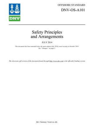
  • 18. DET NORSKE VERITAS AS Amended October 2014 Offshore Standard DNV-OS-A101, July 2014 Ch.2 Sec.1 Design principles and accidental loads – Page 18 — structure supporting hydrocarbon containing equipment — hydrocarbon piping and piping support that can lead to escalation of the incident (drag load). Interpretation: The drag load applies to piping and structure less than 1 m in diameter or cross section main dimension. For items with dimension larger than 1 m, the DAL pressure should be used. ––––––––––––––– end of Interpretation ––––––––––––––– 3.6.6 In a naturally ventilated compartment the explosion load given by the explosion overpressure and duration is mainly determined by the volume of the compartment, fraction of the total compartment sides that is open to free air and the level of congestion. Guidance note: A naturally ventilated compartment is defined by a volume with sides that are either solid walls or decks, or bordering to free, fresh air. If the compartment is located far enough from a neighbouring compartment (typically 20 m) only then it can be regarded as a single, standalone compartment. The fraction of the total compartment side that is open to free air is called the relative ventilation area E.g. for compartment volumes of approximately 1000 m3 and relative ventilation area of about 0.5 (can be a cubic compartment that is fully open on 3 of 6 equal sides), ignition for stoichiometric gas mixtures is expected to lead to pressures of approximately 100 kPa (1 barg) in cases with medium level of congestion. High level of congestion may increase the pressure with a factor of 2 to 3. Larger volume also tends to increase the pressure. ---e-n-d---of---G-u-i-d-a-n-c-e---n-o-t-e--- 3.6.7 Regarding internal layout of naturally ventilated explosion areas. The large items such as large vessels and LER/LIR rooms, etc. should be located centrally in order to avoid blocking of air ventilation and explosion venting. If located along the edges of the process areas, vessels should be turned towards the inner parts of the process area to give minimum blockage along the borders. It is assumed that the process plant is designed with a suitable blowdown system and deluge system in accordance with a recognised code (e.g. DNV-OS-E201), in order to avoid possible pressure vessel rupture. Table 1-1 Categorization of naturally ventilated offshore oil and gas areas wrt explosion DAL pressures. The curve letter identifies to pressure curves in Figure 1-1 to be used Congestion /density level Operation Confinement by blastwalls and solid decks Typical unit type DAL on Weather cladding Curve no.Confinement level Blastwalls and solid decks High to normal Production Confined 1 or 2 blastwalls, open or solid deck 6 m or more above FPSO, FLNG, Semi sub, fixed Blastwall (s) Windwalls more than 50% A No windwalls B Open No blastwalls open or deck above (FPSO, FLNG) FPSO, FLNG, Turrets Deck Windwalls more than 50% B No windwalls D Less congested Drilling Confined 1 or 2 blastwalls, open or solid deck 6 m or more above Drilling rig, Integrated prod/drill Blastwall (s) Windwalls more than 50% B No windwalls C Open No blastwalls open or deck above Drilling rig Deck Windwalls more than 50% C No windwalls E Less congested Tank deck/ crude piping area or similar Confined 1 or 2 blastwalls, and plated deck above Tank decks (FPSO, FLNG) Blastwall (s) Windwalls more than 50% E No windwalls F Open No blastwalls, plated deck above Open area on tank deck deck Windwalls more than 50% F No windwalls G
  • 19. DET NORSKE VERITAS AS Amended October 2014 Offshore Standard DNV-OS-A101, July 2014 Ch.2 Sec.1 Design principles and accidental loads – Page 19 Figure 1-1 DAL pressures as a function of volume of the congested area, the explosion volume. The curves are defined in Table 1-1. 3.6.8 The explosion DAL pressures in enclosed areas handling hydrocarbons (e.g. STP or STL rooms, internal moonpools and shale shaker rooms) considering bulkheads that need to remain intact after an explosion, e.g. towards storage tanks, shall be designed for an overpressure of 4 barg in case no venting panels are installed. A pulse duration of 1s should be used. 3.6.9 If venting panels are installed, they need to cover more than 20% of the surface area of the explosion volume. The relieving pressure of the venting panels (explosion panels) should be between 0.05 and 0.1 barg. The DAL pressure on the stronger walls and decks can then be set to 2 barg, with pulse duration of 0.3 s. 3.6.10 For compartments where the length to diameter ratio, L/D, is greater than 3, the long flame acceleration distance available tends to result in higher pressures than given in Figure 1-1. The diameter can be estimated as D = where A is the smallest cross-sectional area. L is the greatest dimension of the compartment/ explosion area. It could be either horizontal or vertical. 3.6.11 Where it is possible for an explosion to propagate from compartment to compartment and for tunnels and chutes where explosion venting can be foreseen at one end only, detailed investigations shall be carried out. 3.6.12 The following items shall be designed to withstand the specified design overpressure: — protective walls — structures capable of blocking escape ways — safety systems (and control lines) — structure supporting hydrocarbon containing equipment — hydrocarbon piping and piping support that can lead to escalation of the incident (drag load). A
  • 20. DET NORSKE VERITAS AS Amended October 2014 Offshore Standard DNV-OS-A101, July 2014 Ch.2 Sec.1 Design principles and accidental loads – Page 20 Interpretation: The drag load applies to piping and structure less than 0.5 m in diameter or cross section main dimension. For items with dimension larger than 0.5 m, the DAL pressure should be used. ––––––––––––––– end of Interpretation ––––––––––––––– 3.6.13 Typical design values are summarised in Table 1-1 with associated Figure 1-1. This shall be read together with the reservations in the text of this subsection. Guidance note: Accurate predictions of explosion overpressures are dependent on numerous variables and therefore specific analysis with use of actual project details is recommended. ---e-n-d---of---G-u-i-d-a-n-c-e---n-o-t-e--- 3.7 Heat loads 3.7.1 Where the living quarters are exposed to a heat load below 100 kW/m2 a passive fire protection rating of A-60 is considered sufficient for the surface facing the source of the heat load. For heat loads above 100 kW/ m2 H-rated protection shall be used. Guidance note: For standard design drilling units the passive fire protection requirements of the IMO MODU Code is considered as acceptable. ---e-n-d---of---G-u-i-d-a-n-c-e---n-o-t-e--- Where radiation levels at lifeboat stations exceeds 4.7 kW/m2, radiation protection shall be provided. 3.7.2 For drilling in water depths of 200 and 400 m the subsea gas blowout rate is reduced by 50% and 75% when reaching the surface, respectively. Potential effects of subsea blowouts shall be considered according to this. 3.7.3 For drilling and production units, heat loads in connection with ignition following loss of containment of hydrocarbons shall be taken as in Table 1-2, unless otherwise documented. These fires shall be used in areas as follow: a) In areas with both gas containing and oil or condensate containing equipment, critical items shall be designed to withstand a two-phase jet fire for 30 minutes and a pool fire for the following 30 minutes. b) In areas with only oil or condensate containing equipment, critical items shall be designed to withstand a pool fire for 60 minutes. c) In areas with only gas containing equipment, critical items shall be designed to withstand a jet fire for 30 minutes. Guidance note: Global average heat load represents the average heat load that exposes a significant part of the process segment or structure. The global average heat load provides the major part of the heat input to the process segment and/ or area and, hence, affects the pressure in the segment. The local peak heat load exposes a small (local) area of the process segment where process segment can be the drill floor or of the structure to peak heat flux. The local peak heat load, with the highest flux, determines the rupture of different equipment and piping within the process segment. ---e-n-d---of---G-u-i-d-a-n-c-e---n-o-t-e--- 3.7.4 The following critical items shall be designed to withstand the specified design heat load: — protective walls — structures supporting hydrocarbon pressure vessels — hydrocarbon piping and piping support that can lead to escalation of the incident — structures capable of blocking escape ways — safety systems — main structure. Table 1-2 Fire DAL for different types of fires Global average heat load (kW/m2) Local peak heat load (kW/m2) Duration (minutes) Two-phase jet fire 100 350 30 + 30 pool Gas jet fires 100 350 30 Pool fire 100 250 60
  • 21. DET NORSKE VERITAS AS Amended October 2014 Offshore Standard DNV-OS-A101, July 2014 Ch.2 Sec.2 Arrangement – Page 21 SECTION 2 ARRANGEMENT 1 Introduction 1.1 Objective The provisions of this section aim to avoid or reduce the effects of hazards on the mobile unit or offshore installation, by means of safe general arrangement of structures, plants and facilities. 1.2 Application The requirements of this section shall be applied to all mobile units and offshore installations. Additional, specific requirements for arrangement of different unit types are given as indicated in Table 2-1. 2 General arrangement 2.1 Segregation of areas 2.1.1 The mobile unit or offshore installation shall be divided into different areas according to the type of activities that will be carried out and the associated hazard potential. Areas of high risk potential shall be segregated from areas of low risk potential, and from areas containing important safety functions. Incident escalation between areas shall be avoided. Interpretation: The effect of prevailing winds and potential for segregation by less hazardous areas should also be considered for area protection. This is also vital for establishing an ESD philosophy. ––––––––––––––– end of Interpretation ––––––––––––––– 2.1.2 The above implies that hazardous areas including drains shall be separated from non-hazardous areas including drains. (Ref. MODU code 6.3.2) 2.1.3 Accommodation and other areas important for safety, such as control stations, shall be located in areas classified as non-hazardous by location, and as far as practicable away from hazardous areas for hydrocarbon processing, hydrocarbon storage, wellheads, risers and drilling. (Ref. MODU code 9.3.1) 2.1.4 Use of firewalls, blast walls, cofferdams etc. shall be considered in cases where segregation by physical distance is not sufficient. (Ref. MODU code 9.3.1) 2.2 Arrangement 2.2.1 Escape, muster and evacuation areas shall not be impaired by smoke or gas. With regard to the dominant operational wind conditions, the general arrangement shall support this aim. 2.2.2 Arrangement of functions and equipment shall take into account the following: — safe escape from working areas — efficient ventilation of hazardous areas — minimal explosion overpressure in case of ignited gas release — access for fire fighting and emergency response — prevention of serious consequences from dropped objects — minimal possibility for escalation of fires and other failures or accidents — safe containment of accidental release of hazardous liquids — planned simultaneous operations. Table 2-1 Additional requirements Reference Unit type Sec.6 Special provisions for Drilling Units and/or Well Intervention Units Sec.7 Special provisions for Floating Production and/or Storage Units Sec.9 Special provisions for LNG Import and Export Terminals and LNG Production Units
  • 22. DET NORSKE VERITAS AS Amended October 2014 Offshore Standard DNV-OS-A101, July 2014 Ch.2 Sec.2 Arrangement – Page 22 Guidance note: ISO 13702 section 13 and Annex B provides useful principles to minimise the effect of explosions. ---e-n-d---of---G-u-i-d-a-n-c-e---n-o-t-e--- 3 Location of plants and equipment 3.1 Location of safety systems 3.1.1 Safety systems shall be located such that they can remain operational during the defined accidental events. Controls for safety systems shall be located where they are accessible and available for safe, simultaneous use during an emergency. Interpretation: 1) The above should include at least fire and gas detection, fire fighting systems, ESD and ballast systems as applicable. 2) Where redundant safety equipment is used, this should not be vulnerable to the same accidental events as the main system. 3) Where control stations or control of safety functions are located in Local Equipment/ Instrument Rooms (LER/LIRs) outside the accommodation block/safe area, special precautions against gas ignition should be provided in the form of airlock, gas detection, ventilation and shutdown. ––––––––––––––– end of Interpretation ––––––––––––––– 3.1.2 The emergency and UPS systems and associated controls etc. shall be self-contained, and located such that they are not vulnerable to events that affect main power supply. 3.1.3 The bridge of mobile installations or units intended for self-propelled transit shall be located and arranged to provide sufficient field of vision for safe navigation and manoeuvring. The requirements in SOLAS Regulation V/22 or MODU Code 14.8 apply. 3.1.4 Field control panels and energy or actuation sources for well control equipment and accumulator operated ESD valves shall be protected from dimensioning accidental events (such as fire, explosion and mechanical impact) to ensure operation of the barrier as necessary. 3.2 Location of air intakes and other openings 3.2.1 Inlets are to be located in non-hazardous areas as high and as far away from any hazardous area as practicable. (Ref. IACS UR D8.3.1) Interpretation: 3 Meters is considered sufficient to cover this requirement. ––––––––––––––– end of Interpretation ––––––––––––––– 3.2.2 Air intakes for internal combustion engines shall be not less than 3 m (10 ft) from the hazardous areas as defined in Sec.3. (Ref. IACS UR D9.11.3) 3.2.3 Exhausts from combustion equipment and ventilation systems shall be located to avoid cross contamination of air inlets. (Ref. IACS UR D8.3.1) 3.2.4 Openings, such as windows, doors, and ventilation ducts, shall normally be avoided in boundaries between main areas. In particular this applies to openings in accommodation spaces, control stations and other areas important for safety which face areas for hydrocarbon processing, hydrocarbon storage, wellheads, risers or drilling. 3.2.5 Requirements for freeboard to prevent uncontrolled flooding through openings in watertight barriers are given in DNV-OS-C301.
  • 23. DET NORSKE VERITAS AS Amended October 2014 Offshore Standard DNV-OS-A101, July 2014 Ch.2 Sec.2 Arrangement – Page 23 3.3 Fired heaters, combustion engines and hot surfaces 3.3.1 Combustion engines in hazardous areas Generally, combustion engines are not to be installed in hazardous areas. When this cannot be avoided, diesel engines are allowed in zone 1 and 2 provided special consideration shall be given to the arrangement. (Ref. MODU code 6.7 and IACS UR D9.10.1) Interpretation: 1) The special precautions should consider the following: — use of segregation and/or fire barriers — gas tight enclosures — overpressure ventilation — gas detection and automatic isolation — insulation or cooling of hot surfaces — a diesel engine protection in compliance with EN-1834-1 2) Similar considerations should also be given to diesel engines outside hazardous areas but left operational after gas has been detected. ––––––––––––––– end of Interpretation ––––––––––––––– 3.3.2 Boilers in hazardous areas Fired boilers are not to be installed in hazardous areas. (Ref. IACS UR D9.10.2) 3.3.3 Other requirements for protection of hot surfaces are presented in DNV-OS-D101. 3.4 Location of flares and vents 3.4.1 Flares and/or burner booms shall be located to avoid ignition of normal or accidental gas releases. Use of dispersion calculations shall be considered. 3.4.2 The flare and vent systems shall comply with API Std. 521/ ISO 23521 or equivalent. The radiant heat intensities or emissions from flares and vent systems shall not exceed the following limits: — 6.3 kW/m2 (2000 Btu/hr./ft2) in areas where emergency actions lasting up to one minute may be required by personnel without shielding but with appropriate clothing — 4.7 kW/m2 (1500 Btu/hr./ft2 in areas where emergency actions lasting several minutes may be required by personnel without shielding but with appropriate clothing — 1.6 kW/m2 (500 Btu/hr./ft2) at any location where personnel are continuously exposed — temperature rating of electrical and mechanical equipment — 50% LEL at any point on the installation where the gas plume from a vent could be ignited or personnel could get into contact with the gas. The most unfavourable weather and process conditions have to be taken into consideration when calculating heat radiation and dispersion. The limits above also apply to abnormal conditions (e.g. flame out of flare system and accidental ignition of vent). 4 Dangerous goods and cranes 4.1 Storage of dangerous goods 4.1.1 Dangerous goods should be stored safely and appropriately according to the nature of the goods. (Ref. MODU Code 14.4.1) Interpretation: 1) Stores for hazardous substances should be segregated from, and located at a safe distance from accommodation spaces and control stations. 2) Areas for storage of flammable, radioactive, explosive or otherwise hazardous substances should be marked with appropriate warning signboards. ––––––––––––––– end of Interpretation –––––––––––––––
  • 24. DET NORSKE VERITAS AS Amended October 2014 Offshore Standard DNV-OS-A101, July 2014 Ch.2 Sec.2 Arrangement – Page 24 4.1.2 Flammable liquids which give off dangerous vapours and flammable gases should be stored in a well- ventilated space or on deck. (Ref. MODU code 14.4.3) Interpretation: 1) Indoor storage areas should have access from open deck. 2) Equipment for storage and handling of cryogenic liquids (e.g. liquid nitrogen) should be located in open areas with efficient natural ventilation. Equipment with potential for significant leakage should be located in a bounded area, which is constructed of materials suitable for sustaining low temperatures. Reference also Sec.9 dealing with LNG terminals. Since evaporating cryogenic gases are heavier than air, care should be taken to ensure that such gases do not contaminate lower modules. ––––––––––––––– end of Interpretation ––––––––––––––– 4.2 Cranes and lay down areas Cranes and lay down areas shall be located so as to minimise the risk of load handling or dropped object damage to systems and structures. (Ref. MODU code 12.1.2) Interpretation: 1) The need for load handling above pressurised hydrocarbon equipment, hazardous inventories, and equipment important for safety should be avoided as far as possible. Suitable impact protection should be provided where such lifting cannot be avoided. 2) Lay down areas should be provided with heavy-duty barriers to prevent damage to adjacent equipment. 3) On floating installations, necessary points for securing of deck loading should be provided. 4) Lay down areas should be located outside hazardous areas. ––––––––––––––– end of Interpretation ––––––––––––––– 5 Other requirements 5.1 Asbestos The principal means of ensuring that no materials containing asbestos are installed on board the vessel rests with the ship builder and the subcontractors by managing procedures for purchasing and installing asbestos free materials. Builders are upon completion of the vessel to issue an Asbestos Free Declaration that includes structures and equipment on board that have been known to contain asbestos, Ref. also MODU Code 2.10.3. Guidance note: IACS UI SC 249 Annex 1 gives an indicative list of components that have been known to contain asbestos. ---e-n-d---of---G-u-i-d-a-n-c-e---n-o-t-e--- 5.2 Railings and barriers Railings and other barriers shall be designed with sufficient strength, height and arrangement such that personnel are protected from falling either overboard or more than 0.8 m to a lower deck level. The guard rails shall have at least three courses so arranged that the lowest rail is not more than 230 mm above the deck or toe board and the highest rail not less than 1 m above the deck. Every deck, gangway, stairway and opening from which an object could drop more than 2 m, shall, where practicable, be provided with a toe board of not less than 150 mm height.
  • 25. DET NORSKE VERITAS AS Amended October 2014 Offshore Standard DNV-OS-A101, July 2014 Ch.2 Sec.3 Hazardous area classification – Page 25 SECTION 3 HAZARDOUS AREA CLASSIFICATION 1 Introduction 1.1 Objective and scope 1.1.1 Objective The provisions of this section is to identify areas where there is the potential for release of flammable gas, vapours or liquids during normal operation, at the same time assess frequency of release and the type of gas/ vapour/liquid that may be released. The resulting hazardous are classification will in turn specify the requirements of the equipment acceptable to install in that area. 1.1.2 Scope Release as a result of accidental events such as blowout or vessel rupture is not addressed by area classification as is addressed in this section, but shall be covered by emergency shut down as is addressed in Sec.4. 1.2 Application 1.2.1 This section applies to all offshore units and installations covered by this standard. For supplementary requirements applicable for special types and services, see Sec.6 to Sec.9. 1.2.2 The standards listed in Table 3-1 are referred to for basic or supplementary information. The code revision applicable is that valid at date of issue of this standard unless otherwise agreed. 1.2.3 Hazardous area classification shall be documented by drawings including location, of air inlets and exhausts. 1.2.4 A schedule of release sources shall be established. Guidance note: IEC 61892-7 paragraph 10.1 and Table C2 provide further information. ---e-n-d---of---G-u-i-d-a-n-c-e---n-o-t-e--- 2 Basic principles 2.1 Definition of hazardous areas 2.1.1 Hazardous areas are all those areas in which explosive gas or air mixture may normally be expected to be present in quantities which can require special precautions for the construction and use of electrical equipment and machinery. (Ref. IACS UR D8.1.2) 2.1.2 Hazardous areas are divided into zones depending upon the grade (frequency and duration) of release: a) Zone 0: in which an explosive gas atmosphere is continuously present or present for long periods. (Typical for continuous grade source present for more than 1000 hours a year or that occurs frequently for short periods). b) Zone 1: in which an explosive gas atmosphere is likely to occur in normal operation. (Typical for primary grade source present between 10 and 1000 hours a year). c) Zone 2: in which an explosive gas atmosphere is not likely to occur in normal operation, and if it does occur, is likely to do so infrequently and will exist for a short period only. (Typical for secondary grade source present for less than 10 hours per year and for short periods only). (Ref. IACS UR D8.1.3) Table 3-1 Reference standards Reference Title IEC 60079-10-1 Electrical apparatus for explosive gas atmospheres - Part 10: Classification of hazardous areas IEC 61892-7 Mobile and fixed offshore units - Electrical installations - Part 7: Hazardous area IMO MODU Code Code for the Construction and Equipment of Mobile Offshore Drilling Units, 2009 API RP 505 Recommended Practice for Classification of Locations for Electrical Installations at Petroleum Facilities Classified as Class I, Zone 0, Zone 1, and Zone 2 IP 15 Energy Institute; Model code of safe practice – Part 15 Area classification code for installations handling flammable fluids
  • 26. DET NORSKE VERITAS AS Amended October 2014 Offshore Standard DNV-OS-A101, July 2014 Ch.2 Sec.3 Hazardous area classification – Page 26 Guidance note: Note that conditions of ventilation may change the zone definition for each grade of release. ---e-n-d---of---G-u-i-d-a-n-c-e---n-o-t-e--- 2.1.3 Non-hazardous areas are areas which are not hazardous according to the definitions in [2.1.1] and [2.1.2], either by safe location, by overpressure or by dilution ventilation. Guidance note: For more details on overpressure ventilation see [3.3]. For more detail on dilution ventilation, see [3.5]. ---e-n-d---of---G-u-i-d-a-n-c-e---n-o-t-e--- 2.2 Hazardous fluids (sources) 2.2.1 The following fluids shall be considered as sources requiring area classification: a) Flammable gas or vapour. b) Flammable liquids which are handled at or above their flashpoint, or which could be heated to the flashpoint after release. c) Flammable liquid that could form a flammable mist. d) Fluids which satisfy the criteria in a), b) or c), and which are present periodically within the plant for 100 hours per year or more (e.g. during start-up). e) Unclassified, flammable liquids containing residual, volatile materials and which are stored under confined, heated conditions give rise to limited area classification. 2.2.2 App.A gives guidance for general categorisation of sources of release based on definitions in [2.1]. 2.3 General principles for area classification 2.3.1 Location of a continuous source within an enclosed area, or in open areas with significant obstructions to ventilation, shall be avoided. 2.3.2 The number and release rate of primary grade sources shall be minimised as far as practicable. Location of a primary grade source within an enclosed area shall as far as practicable be avoided. 2.3.3 It is not normally acceptable to locate open, non-hazardous areas (significantly) surrounded by hazardous areas. 2.3.4 Openings, penetrations or connections between areas of different hazardous area classification shall be avoided, e.g. through ventilation systems, air pipes or drain systems. 2.4 Extent of the hazardous zone 2.4.1 The extent of the hazardous area depends on the rate of release, fluid properties and actual ventilation conditions as influenced by use of windshields, ventilation arrangements, structural arrangements (e.g., low deck head), etc. (Ref. IACS UR D8.1.4) 2.4.2 The extent of the hazardous area shall be based on one of the recognised standards listed in Table 3-1. 2.4.3 Where there is a potential for large releases in operational situations covered by hazardous area classification, e.g. process vents, the extent of the zone shall be larger than the boundary of 50% LEL concentration. This shall be determined by a dispersion analysis. The resulting zone will be defined as Zone 1 or Zone 2 depending on likelihood of release. 2.4.4 For additional requirements, see Sec.6 for drilling units and Sec.7 for production and storage units. 3 Openings, access and ventilation conditions 3.1 General 3.1.1 Adequate ventilation is required to ensure that releases are rapidly dispersed. The adequacy of ventilation conditions shall be justified and documented. (Ref. MODU code 6.4.1)
  • 27. DET NORSKE VERITAS AS Amended October 2014 Offshore Standard DNV-OS-A101, July 2014 Ch.2 Sec.3 Hazardous area classification – Page 27 Interpretation: Adequacy of ventilation should prevent stagnant areas and achieve a minimum of 12 volumetric air changes per hour. Open areas without significant obstructions are considered to have adequate ventilation if air velocities are rarely below 0.5 m/s and frequently above 2 m/s. ––––––––––––––– end of Interpretation ––––––––––––––– 3.1.2 Any connection between hazardous areas of different classification and between hazardous and non- hazardous systems shall be designed to eliminate or control the risk of ingress of hazardous material from one system to the other due to incorrect operation or leaks. (Ref. MODU code 6.3.2) 3.2 Openings and access 3.2.1 Except for operational reasons access doors or other openings shall not be provided between: a non- hazardous space and a hazardous zone; a Zone 2 space and a Zone 1 space. (Ref. MODU code 6.3.1) 3.2.2 Where such access doors or other openings are provided, any enclosed space having a direct access to any Zone 1 location or Zone 2 location becomes the same zone as the location except that: a) an enclosed space with direct access to any Zone 1 location can be considered as Zone 2 if: i) the access is fitted with a gas-tight door opening into the Zone 2 space, and ii) ventilation is such that the air flow with the door open is from the Zone 2 space into the Zone 1 location, and iii) loss of ventilation is alarmed at a manned station; b) and enclosed space with direct access to any Zone 2 location is not considered hazardous if: i) the access is fitted with a self-closing gas-tight door that opens into the non-hazardous location, and ii) ventilation is such that the air flow with the door open is from the non-hazardous space into the Zone 2 locations, and iii) loss of ventilation is alarmed at a manned station; c) an enclosed space with direct access to any Zone 1 location is not considered hazardous if: i) the access is fitted with gas-tight self-closing doors forming an airlock, and ii) the space has ventilation overpressure in relation to the hazardous space, and iii) loss of ventilation overpressure is alarmed at a manned station. (Ref. MODU code 6.3.1) Interpretation: 1) Alarm delay of up to 30 seconds for loss of overpressure may be applied for the above cases to minimise spurious alarms when doors are intentionally opened. 2) Immediate remedial action to restore ventilation should be taken upon identified loss of mechanical ventilation. 3) Failure or loss of overpressure ventilation and coincident gas detection (in adjacent area, in HVAC inlets or next to any entrance doors) requires isolation of all non-Ex equipment inside the room as the enclosed space then is considered to be hazardous. ––––––––––––––– end of Interpretation ––––––––––––––– 3.2.3 Airlocks The requirements for airlocks below apply when they are installed to prevent smoke or gas ingress. Airlocks shall consist of gas tight steel bulkheads and gas tight self-closing doors. Airlocks between zone 1 and non-hazardous space shall be classified as zone 2 and shall be adequately ventilated. (Ref. MODU code 6.2.4.8 and 6.4.1)