This document provides guidance on the selection and use of subsea leak detection systems. It summarizes current industry experience with subsea leak detection technologies and methods. The document covers relevant regulations, field experience to date, available technologies and their characteristics. It also provides guidance on designing, installing, operating, calibrating and improving subsea leak detection systems to reliably detect hydrocarbon discharges to the environment.


![DET NORSKE VERITAS
Recommended Practice DNV-RP-F302, April 2010
Page 23
advanced stage in the development of activities and their meth-
ods of operation which indicate the practical suitability of par-
ticular techniques for providing in principle the basis for
emission limit values designed to prevent and, where that is not
practicable, generally to reduce emissions and the impact on
the environment as a whole:
- "techniques" shall include both the technology used and the
way in which the installation is designed, built, maintained,
operated and decommissioned,
- "available" techniques shall mean those developed on a scale
which allows implementation in the relevant industrial sector,
under economically and technically viable conditions, taking
into consideration the costs and advantages, whether or not
the techniques are used or produced inside the Member State
in question, as long as they are reasonably accessible to the
operator,
- "best" shall mean most effective in achieving a high general
level of protection of the environment as a whole.”
The BAT principle is also referenced in PSA Norway’s Frame-
work regulation /21/, section 9, paragraph 2:
“In effectuating risk reduction the party responsible shall
choose the technical, operational or organisational solutions
which according to an individual as well as an overall evalua-
tion of the potential harm and present and future use offer the
best results, provided the associated costs are not significantly
disproportionate to the risk reduction achieved.”
From the guideline to section 9:
“The second paragraph expresses the principle of best availa-
ble technology (the BAT principle). This entails that the party
responsible for the petroleum activities must base its planning
and operation on the technology and methods that, based on
an overall assessment, produce the best and most effective
results.”
More information can be found at
http://eippcb.jrc.es/
http://ec.europa.eu/environment/air/pollutants/stationary/
ippc/index.htm
B.3 THE UNITED KINGDOM
The Health and Safety Executive (HSE) in the United King-
dom have the Pipelines Safety Regulations [PSR] (SI 1996/
825) /27/ as the key regulations concerning pipeline safety and
integrity. There are at present no specific regulations concern-
ing subsea production systems. The regulations came into
force in 1996, replacing earlier prescriptive legislation on the
management of pipeline safety with a more integrated, goal-
setting, risk based approach encompassing both onshore and
offshore pipelines. PSR does not cover the environmental
aspects of accidents arising from pipelines but compliance
with the regulations will help to ensure that a pipeline is
designed, constructed and operated safely, provide a means of
securing pipeline integrity and thereby will contribute by
reducing risks to the environment.
More specifically in relation to pipeline leak detection sys-
tems which are covered (but not explicitly) by Reg. 6 of PSR -
Safety systems. The regulation states:
“The operator shall ensure that no fluid is conveyed in a pipe-
line unless it has been provided with such safety systems as are
necessary for securing that, so far as is reasonably practica-
ble, persons are protected from risk to their health & safety.”
However, the associated PSR guidance L82 booklet (ISBN 0
7176 1182 5) states:
“36 Safety systems also include leak detection systems where
they are provided to secure the safe operation of the pipeline.
The method chosen for leak detection should be appropriate
for the fluid conveyed and operating conditions.”
HSE Information relating to Pipeline safety and integrity can
be found on the HSE web http://www.hse.gov.uk
B.4 THE UNITED STATES
Pipeline and Hazardous Materials Safety Administration, DOT
Part 195 - Transportation Of Hazardous Liquids By Pipeline
/26/
§ 195.134 CPM leak detection.
“This section applies to each hazardous liquid pipeline trans-
porting liquid in single phase (without gas in the liquid). On
such systems, each new computational pipeline monitoring
(CPM) leak detection system and each replaced component of
an existing CPM system must comply with section 4.2 of API
1130 in its design and with any other design criteria addressed
in API 1130 for components of the CPM leak detection sys-
tem.”
§ 195.452 Pipeline integrity management in high consequence
areas.
“Leak detection. An operator must have a means to detect
leaks on its pipeline system. An operator must evaluate the
capability of its leak detection means and modify, as neces-
sary, to protect the high consequence area. An operator’s eval-
uation must, at least, consider, the following factors — length
and size of the pipeline, type of product carried, the pipeline’s
proximity to the high consequence area, the swiftness of leak
detection, location of nearest response personnel, leak history,
and risk assessment results.”
Alaska Department Of Environmental Conservation. 18 AAC
75
“Oil and Other Hazardous Substances Pollution Control”,
Revised as of October 9, 2008 /25/:
18 AAC 75.055 Leak detection, monitoring, and operating
requirements for crude oil transmission pipelines.
“(a) A crude oil transmission pipeline must be equipped with a
leak detection system capable of promptly detecting a leak,
including
(1) if technically feasible, the continuous capability to detect a
daily discharge
equal to not more than one percent of daily throughput;
(2) flow verification through an accounting method, at least
once every 24 hours;
and Register 188, January 2009 ENVIRONMENTAL CON-
SERVATION 12
(3) for a remote pipeline not otherwise directly accessible,
weekly aerial surveillance, unless precluded by safety or
weather conditions.
(b) The owner or operator of a crude oil transmission pipeline
shall ensure that the incoming flow of oil can be completely
stopped within one hour after detection of a discharge.
(c) If aboveground oil storage tanks are present at the crude
oil transmission pipeline facility, the owner or operator shall
meet the applicable requirements of 18 AAC 75.065, 18 AAC
75.066 and 18 AAC 75.075.
(d) For facility oil piping connected to or associated with the
main crude oil transmission
pipeline, the owner or operator shall meet the requirements of
18 AAC 75.080. (Eff. 5/14/92,
Register 122; am 12/30/2006, Register 180)
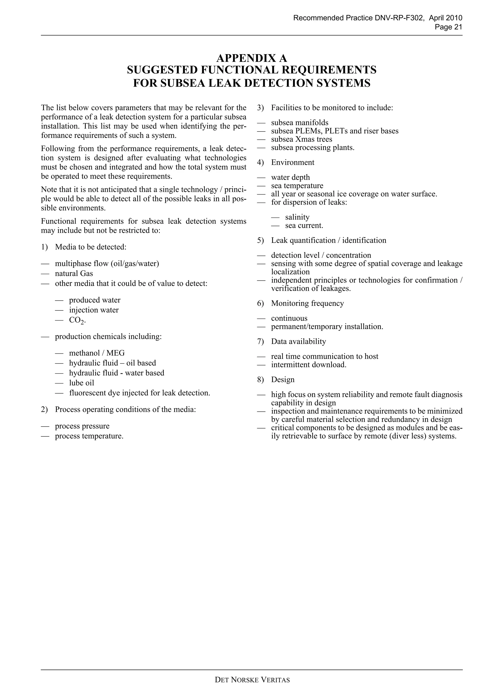
18 AAC 75.425. Oil discharge prevention and contingency
plan contents.
(a) An oil discharge prevention and contingency plan submit-
ted for approval under 18 AAC 75.400 - 18 AAC 75.495 must
be in a form that is usable as a working plan for oil discharge
prevention, control, containment, cleanup, and disposal. A](https://image.slidesharecdn.com/rp-f3022010-04-150513092724-lva1-app6891/75/Rp-f302-2010-04-23-2048.jpg)

![Recommended Practice DNV-RP-F302, April 2010
Page 32
DET NORSKE VERITAS
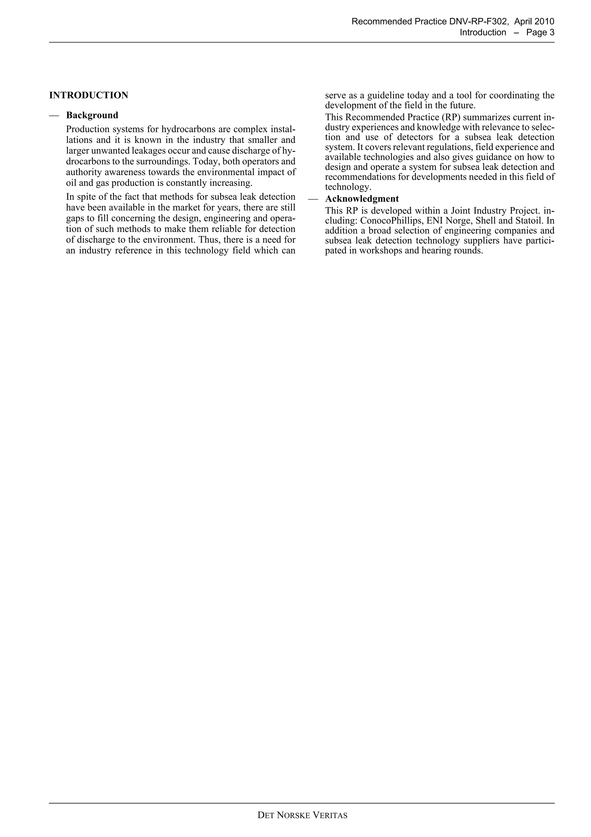
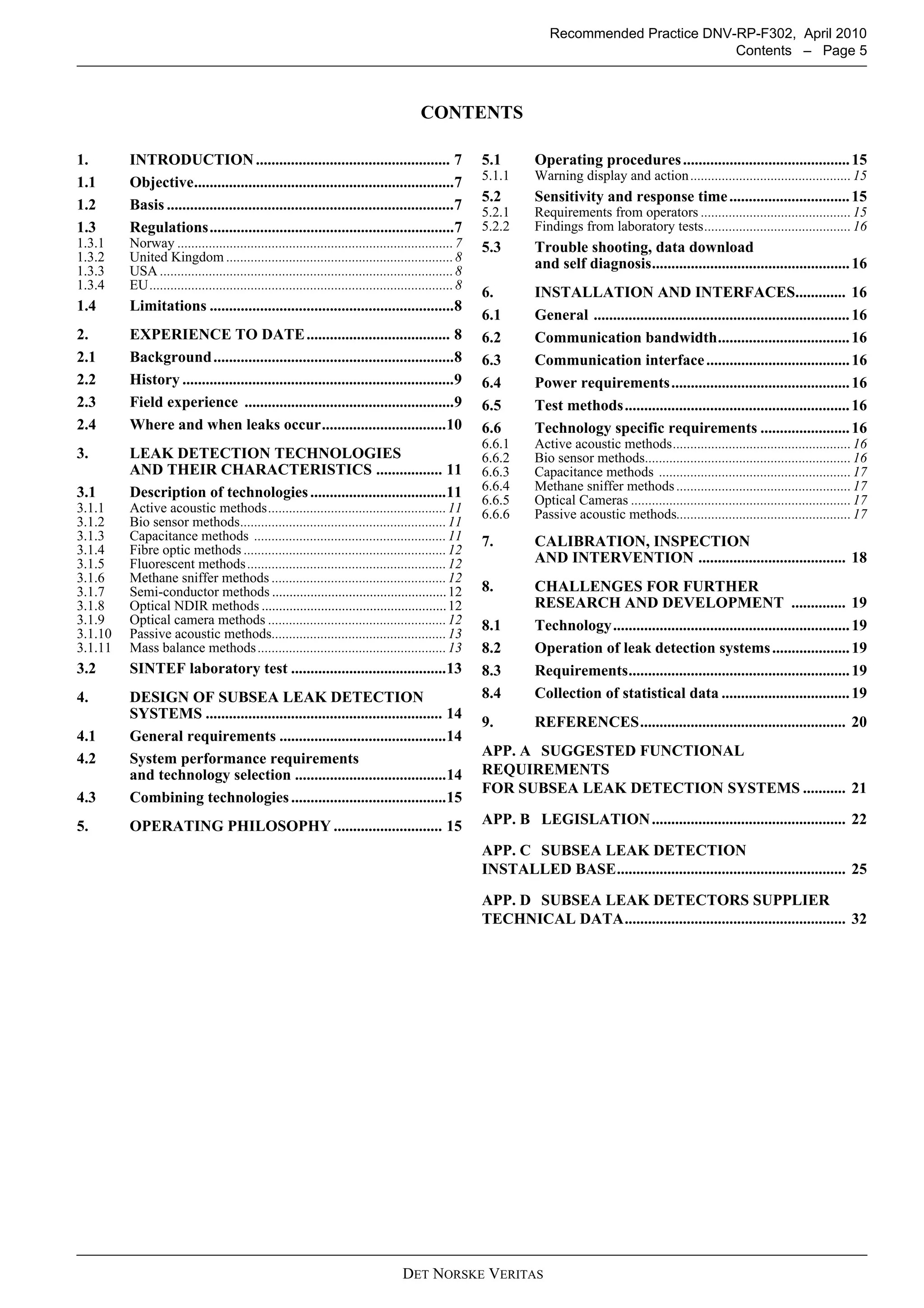
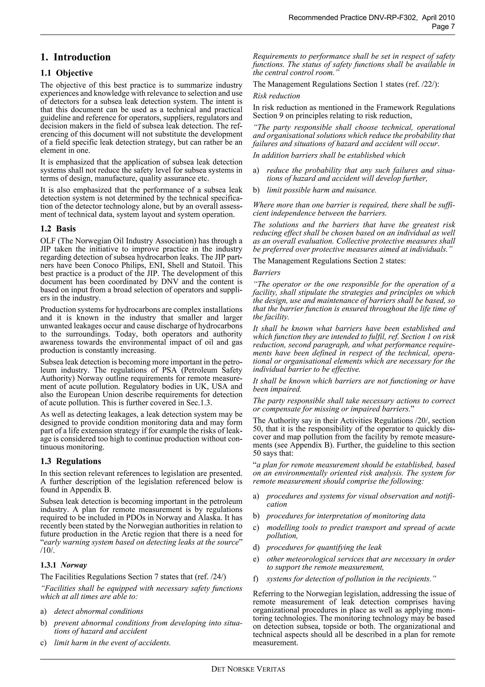
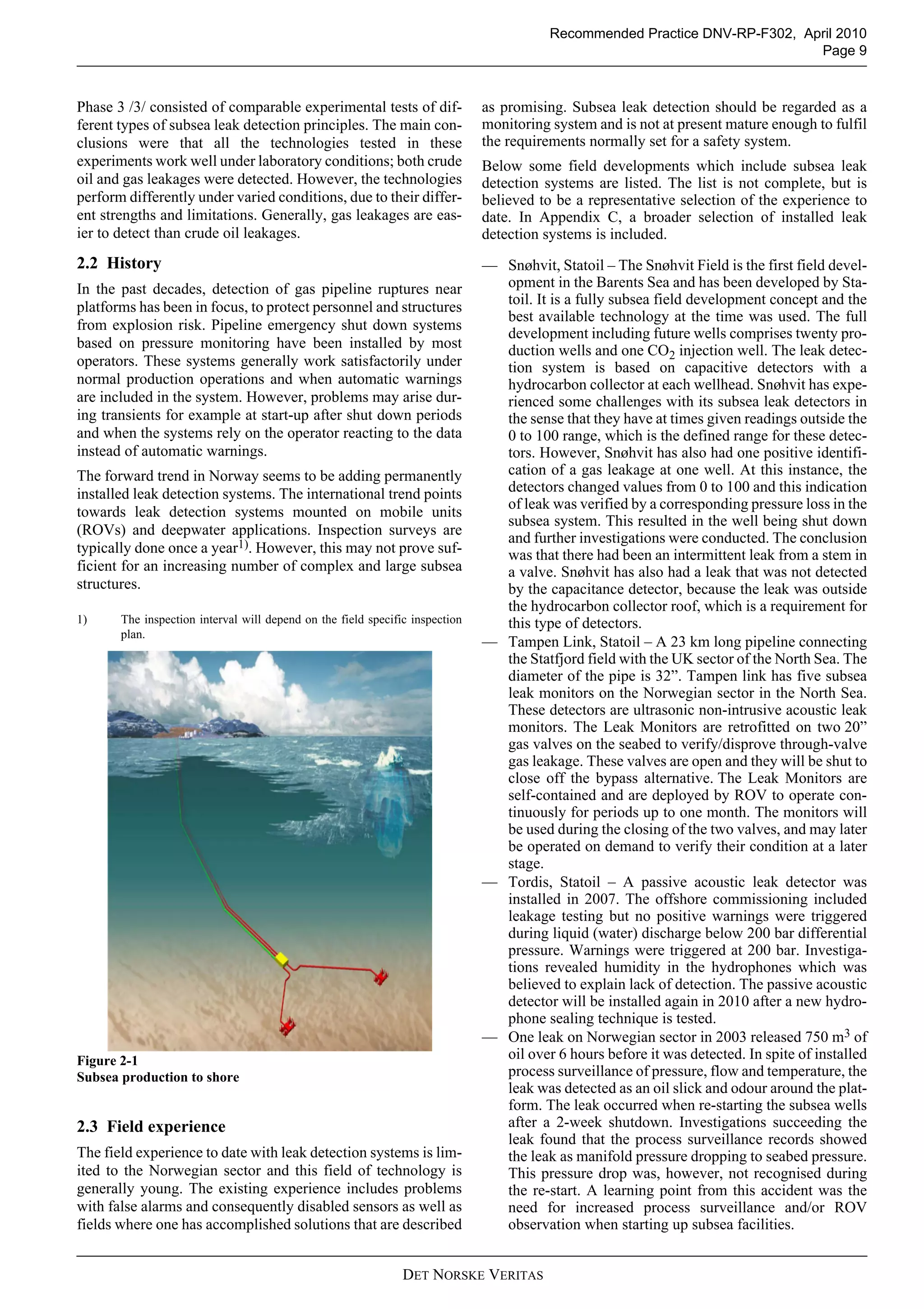
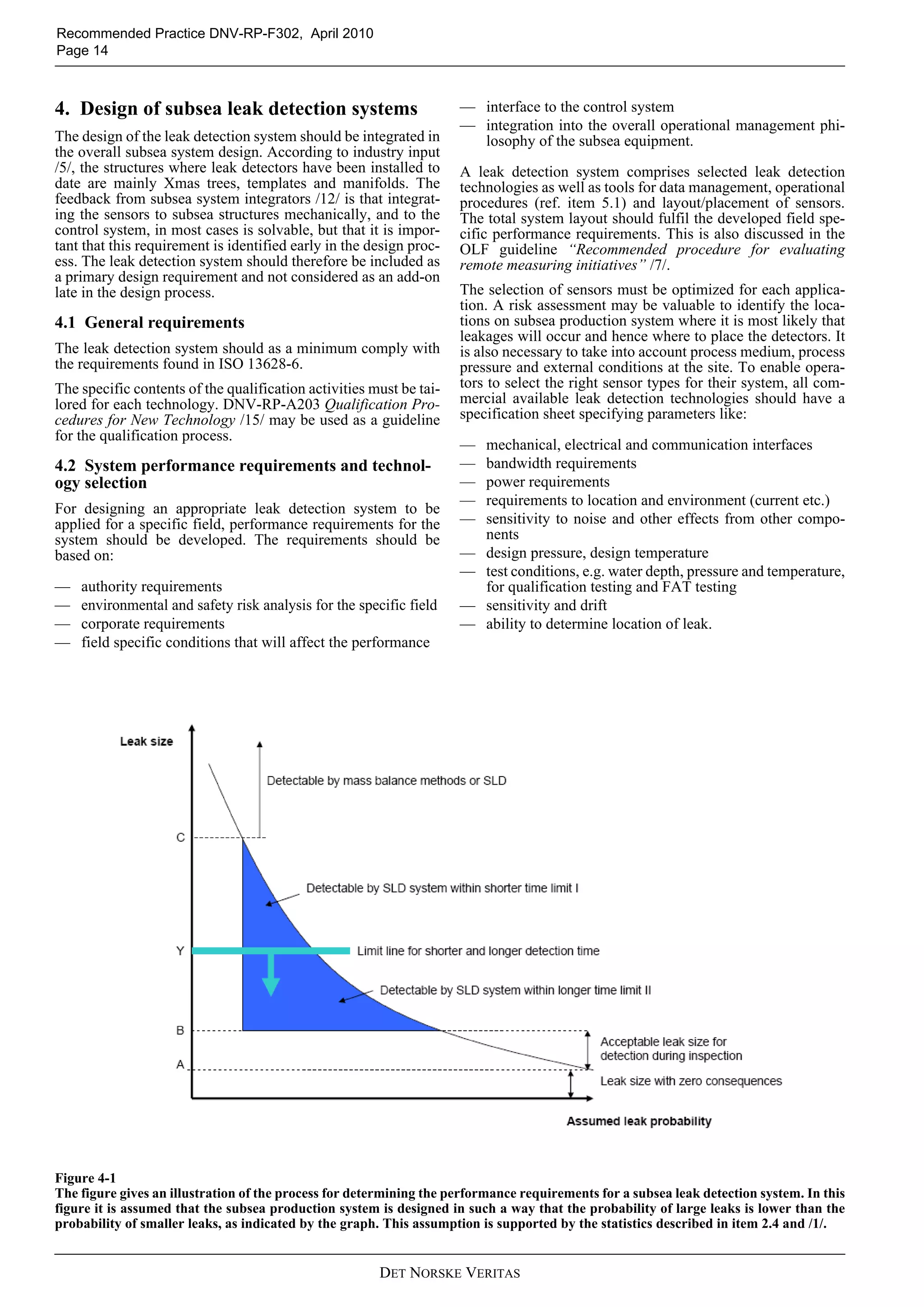
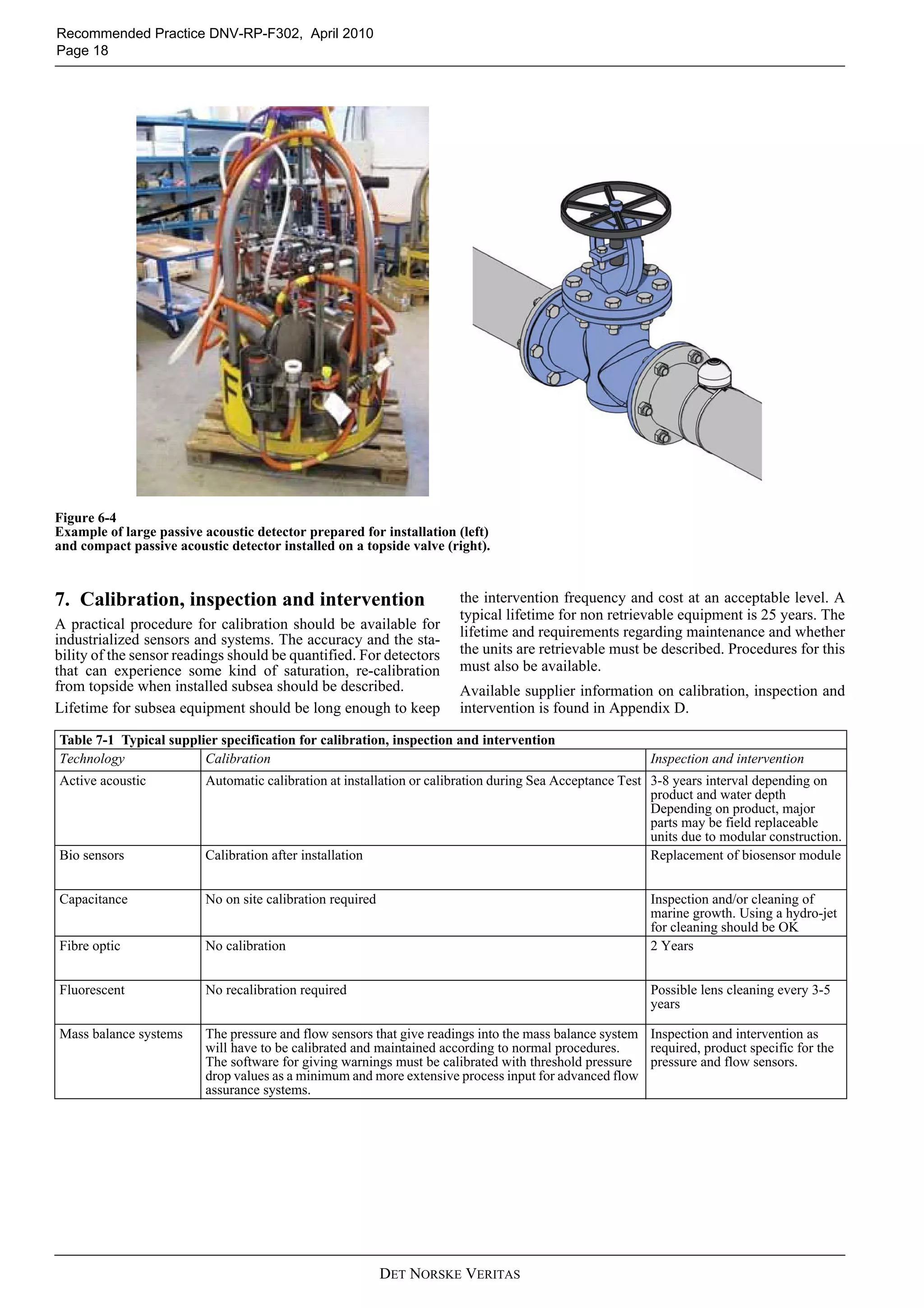
APPENDIXD
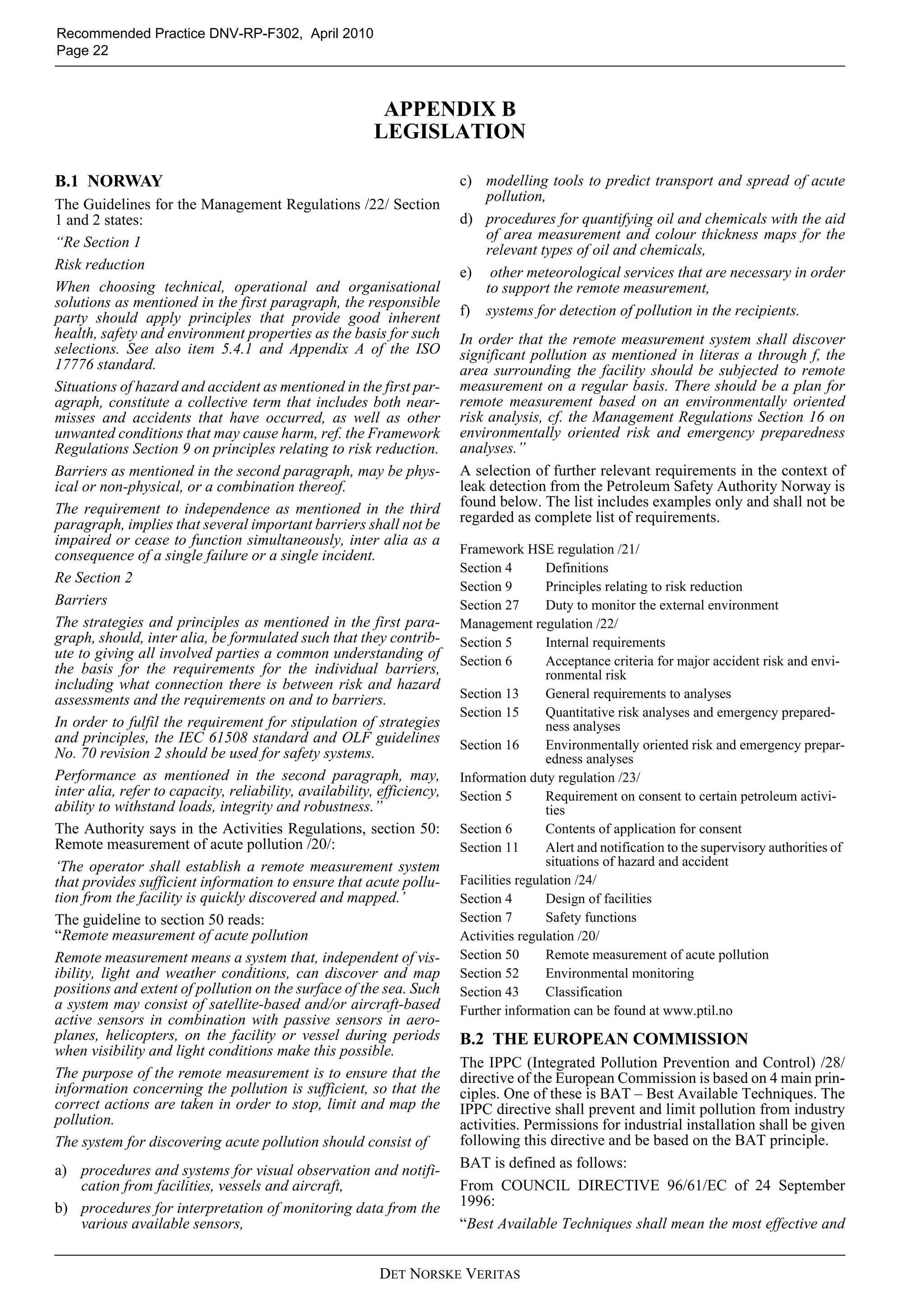
SUBSEALEAKDETECTORSSUPPLIERTECHNICALDATA
TableD-1Detectors-SupplierTechnicalData
Tech-
nology
Calibra-
tion/
Re-cali-
bration
Mainte-
nance
Mechani-
calinter-
face
Weight
[kg]
DimensionsConnec-
tionto
power
andcom-
munica-
tion
Power
need
Band-
width
need
Maturity1Detectablerelease
limitorotheraccu-
racyinformation
Detectable
media
Detection
range
Reliabil-
itydata2
Design
life
[years]
Water
depth
[m]
Tem-
pera-
ture
[°C]
Active
acoustic
Calibra-
tiondur-
ingSea
Accept-
anceTest
3-5
years
interval
Mounted
onROV
skidor
directlyto
template
structure.
Willbe
designedto
beROV
retievable.
Receive
array9.6
(dry),
subsea
bottle
24.8
(dry),
transmit
array4.5
(dry),
Receiver:
102x496x
131mm
Transmit-
ter:240x86
x99mm
Subsea
Bottle:
530.9x
174mm
48V,
Ethernet
40W-
100W
High,
develop-
ment
goalis
1-
10Mbit
ethernet
interface
Baseline
offshore
product:
Commer-
ciallydeliv-
ered.
Subseaver-
sion:Con-
cept
Smallgasleakages
(0.35mmnozzle,2
barpressurediffer-
ence)detectedat
about30meters.
Fluidleakfrom5mm
nozzlewith15bar
pressuredifference
detectedat50m
Notdepend-
entonchem-
ical
compoundas
longas
acoustic
impedanceis
differentto
thatofsea-
water.
dependson
leaksizeand
media.Small
gasleaksseen
upto125m
range.Fluid
seenupto50m
range(maxi-
mumtestrange
todate
NA*NA*400
and
6000
ver-
sions
avail-
able
-5to40
(opera-
tion)
-30to
55
(stor-
age)
Cali-
brates
automati-
callyat
installa-
tion.No
recalibra-
tion
needed.
Deep-
ening
on
water
depht
from4-
8years
interval
ROV
mountable
onXmas
tree,nopre
installation
required
<11kg
com-
plete
unit
(dry)
226x62x
154mm
15-36V
100Mb/s
Ethernet
16Mb/s
RS-485
Typ:
15W
<30W
-
depend
enton
require
d
updat-
ingrate
Depend-
entom
requier-
ment
and
infroma-
tion,can
below
9600
Baud-
system
spesific
PrototypesAngularresolution<
0.75°
Rangeresolution<
10mm
Notdepend-
entonchem-
ical
compoundas
longas
acoustic
impedanceis
differentto
thatofsea-
water.
Anglehorizon-
tal90°or120°
Anglevertical
20°
Range1to<
100m
NA*25300or
3000
-20-60
Biosen-
sors
Calibra-
tionafter
installa-
tion
Replace
mentof
biosen-
sor
module
Installedin
asensor
rackinte-
gratedorin
proximity
ofthemon-
itored
structure
Biosen-
sormod-
ule:2-3
(inair)
Prototype
racksare2
mx0.4mx
0.4m(phys-
ical,chemi-
caland
biological
sensor
array)
Con-
nectedto
subsea
control
system
viacable.
RS-485
orEther-
net
approx
.10W
LowPilots
installedfor
shallow
water.Con-
ceptfor
deepwater
<0.06ppmon
hydrocarbons(raw
oil)
Notdepend-
entonchem-
ical
compound,
specification
willdepend
onselected
biosensor.
Dependingon
leaksize,
mediaandsea
current
(upstream/
downstream
approach)
NA*NA*100
(500
from
2012)
Ocean
temper-
ature
range.](https://image.slidesharecdn.com/rp-f3022010-04-150513092724-lva1-app6891/75/Rp-f302-2010-04-32-2048.jpg)
![Recommended Practice DNV-RP-F302, April 2010
Page 33
DET NORSKE VERITAS
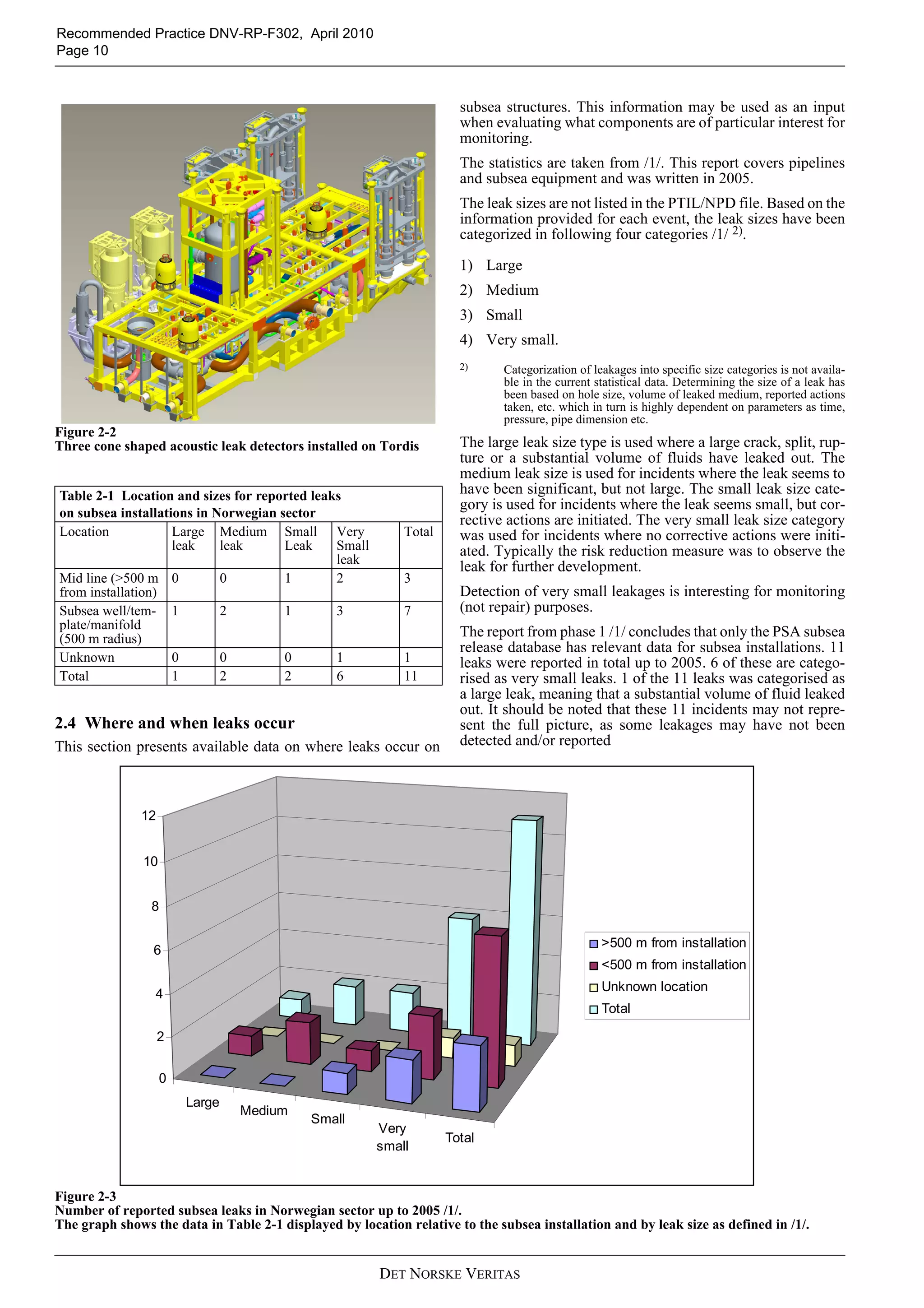
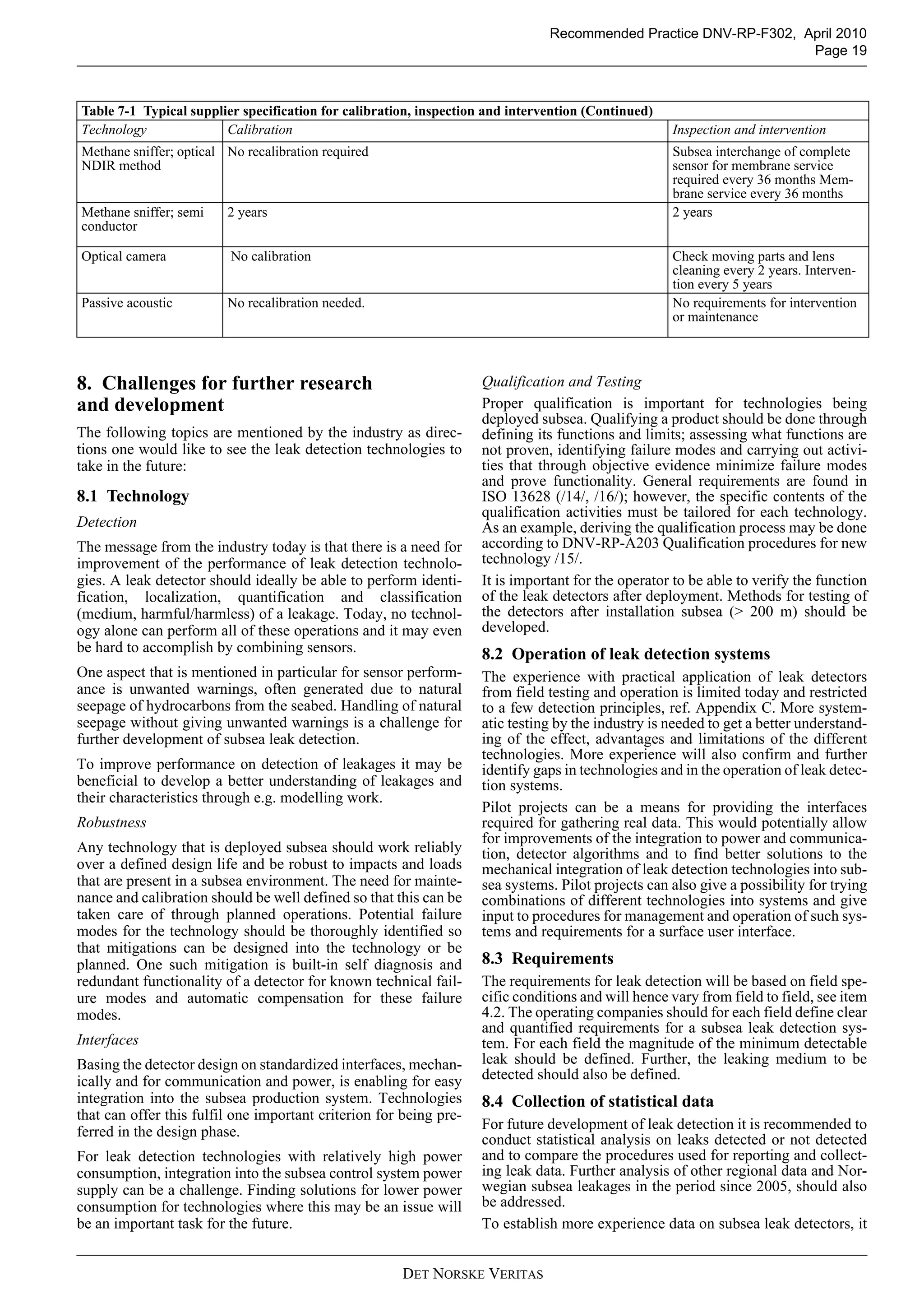
Capaci-
tance
Norecali-
bration
required
Clean-
ing.
Usinga
hydro-
jet
should
beOK
Boltedon
tocover
aboveleak
point.
<5<1000ccm
=1l
4-20mA
and
CANBus
24V,
0.5W
LowCommer-
ciallydeliv-
eredand
qualified
Evensmallleaksare
detected.
Allhydro-
carbons
Dependingon
overallsystem
design.
Approx.
300units
deliv-
ered,no
returns
andno
reports
offailure
after
installa-
tion.
254000,
deepe
rif
requir
ed.
Allsea
temper-
atures
OK.
Fiber
optic
Nocali-
bration
2YearsSystem
Specif
20kg-
surface
equip-
ment
56x45x15c
ms
Ethernet
atsur-
face
240/
110v
300w
at
surace
System
spefic
Concept
tested(top-
sidefor
pipelines)
Gasbubbleat1Hz
detected.Lowpres-
surethreshold
approx2bar.No
upperlimit
Notdepend-
entonchem-
ical
compound,
detects
vibrations
causedbya
leak
Dependenton
energy,but
typically5m
NA*204000+5to
+50
(opera-
tion)
Fluores-
cent
Norecali-
bration
required
Possi-
blelens
clean-
ing
every
3-5
years
Boltedon
toXTand
SPS
10-15in
air
Ø200x200m
m,
100x200x20
0mm
4wire
Tronic/
Canbus/
4-20mA
24V,
<10W
LowInusewith
ROV.Con-
ceptversion
forsubsea
Widedynamic
range.<100ppm
@4m
Crudeoil.
Production
fluidswith
fluorescent
markers
3-5mNA*NA*NA*NA*
Meth-
ane
sniffer;
optical
NDIR
method
Norecali-
bration
required
Mem-
brane
service
every
36
months
ROV
mountable/
inter-
changea-
blebywet-
mateable
plugsand
ROVhan-
dle
5,2inair
2,7in
water
Diameter
90mm,
length
700mm
wet-
matea-
bleplug
3Wlowcommer-
ciallydeliv-
ered
verysmallleaksMethaneNA*Stability
3years.
Newver-
sion5
years
106000-4upto
50
Meth-
ane
sniffer;
semi
conduc-
tor
2years2yearsadaptable
tofitappli-
cation
0.5kgin
water
Ø49mmx
200mm
wet-
matea-
bleplug
1WLowBaseline
product
commer-
ciallydeliv-
ered.
Concept
versionfor
subsea
verysmallleaksMethanelowerrange
limit1nM
(oceanicback-
ground)
lifetime
5years
540000-30
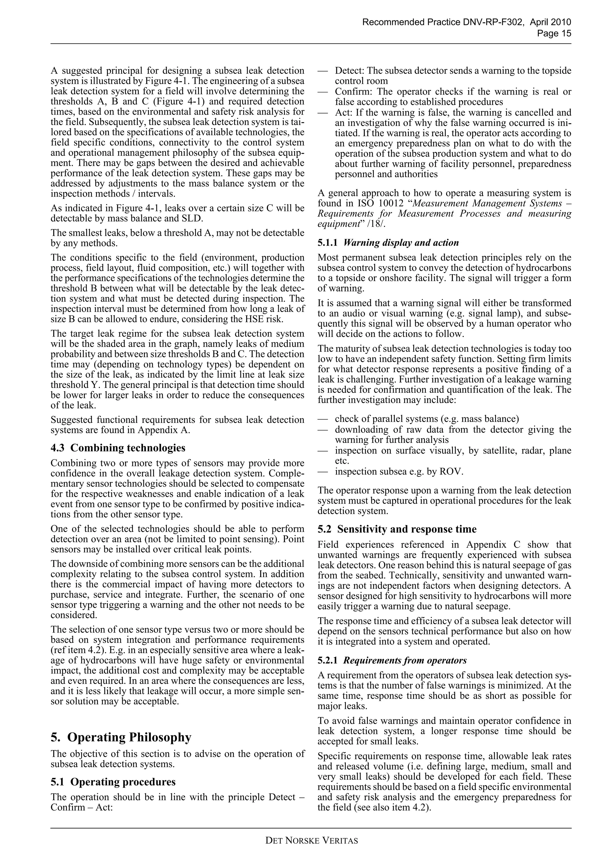
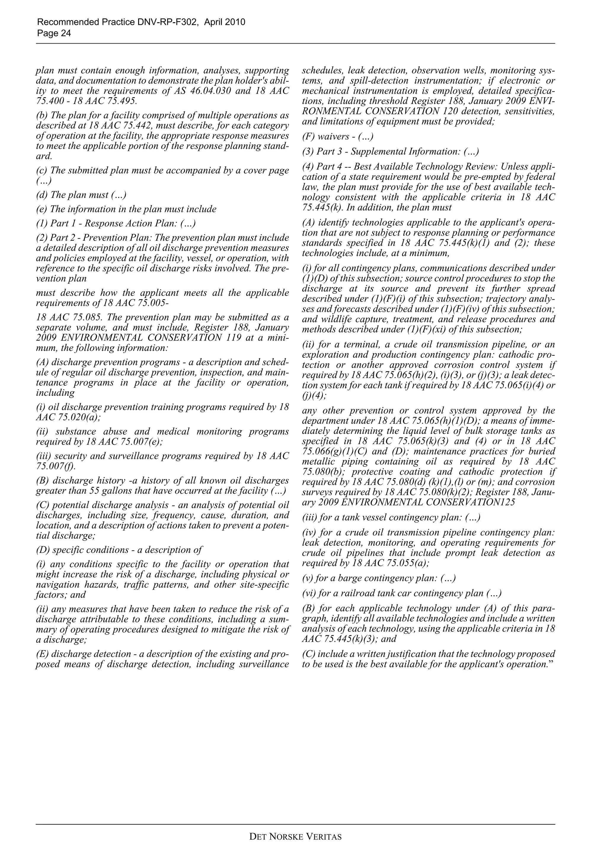
TableD-1Detectors-SupplierTechnicalData(Continued)
Tech-
nology
Calibra-
tion/
Re-cali-
bration
Mainte-
nance
Mechani-
calinter-
face
Weight
[kg]
DimensionsConnec-
tionto
power
andcom-
munica-
tion
Power
need
Band-
width
need
Maturity1Detectablerelease
limitorotheraccu-
racyinformation
Detectable
media
Detection
range
Reliabil-
itydata2
Design
life
[years]
Water
depth
[m]
Tem-
pera-
ture
[°C]](https://image.slidesharecdn.com/rp-f3022010-04-150513092724-lva1-app6891/75/Rp-f302-2010-04-33-2048.jpg)
![Recommended Practice DNV-RP-F302, April 2010
Page 34
DET NORSKE VERITAS
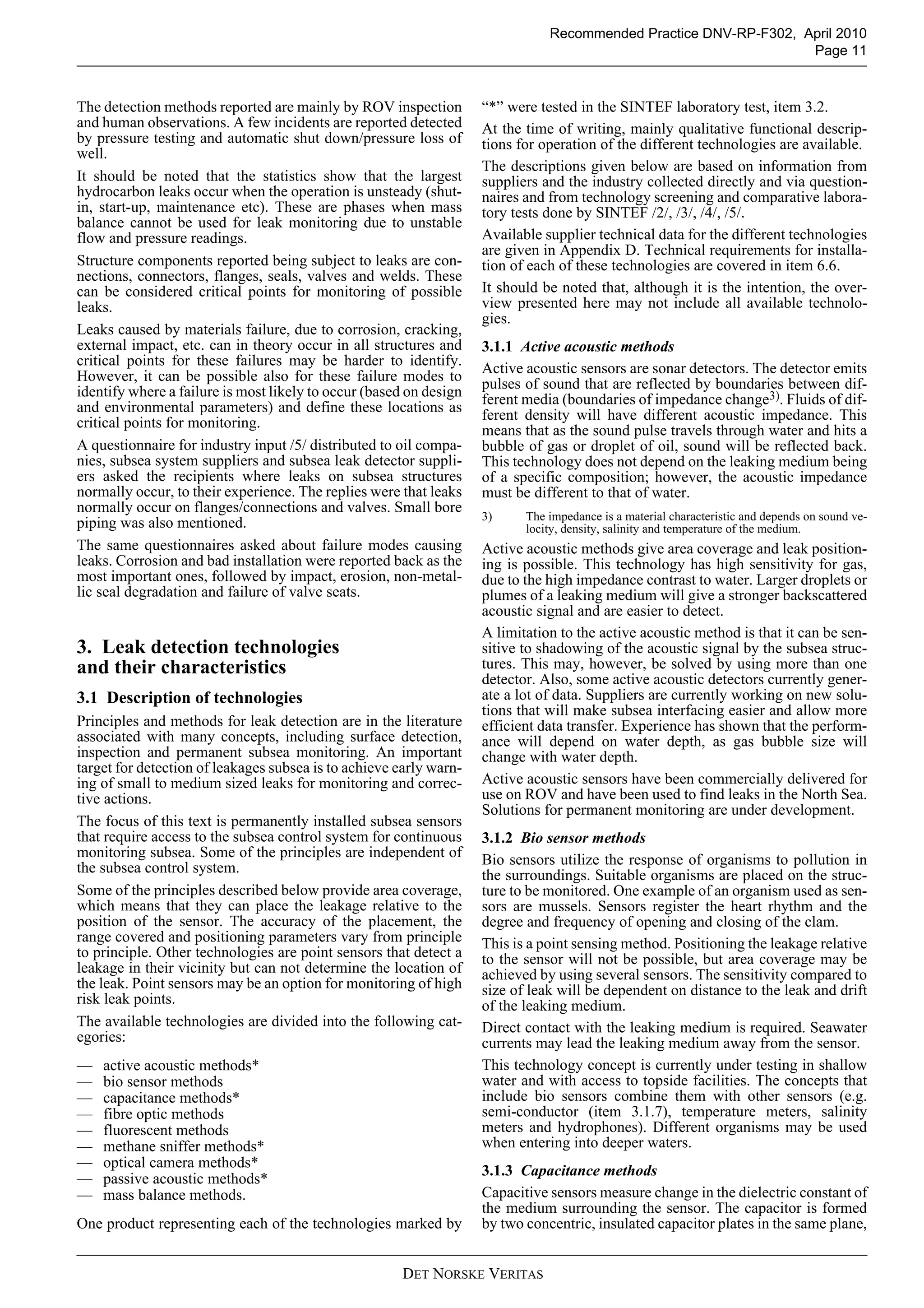
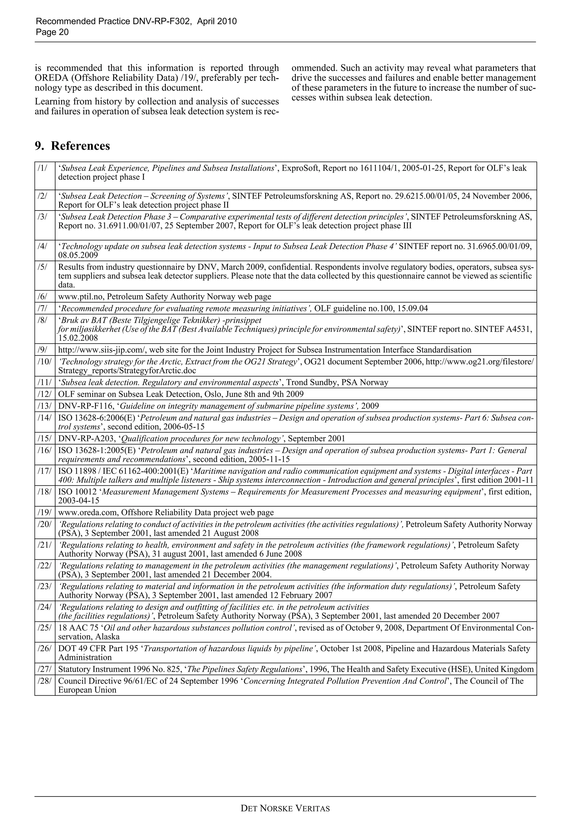
Optical
camera
NoCheck
mov-
ing
parts
and
lens
clean-
ing
every2
years.
Inter-
vention
every5
years
ROV
mountable
onXmas
tree,nopre
installation
required
camera
3.2in
air.
Light
4.1in
air.
ø100x200m
m.
880*550*45
0
4wire
tronic.
Commu-
nication
via
power
line.
96WMedium
.Com-
munica-
tionon
separate
lineor
viasub-
seacon-
trol
system
Firstproto-
typewith
patternrec-
ognition
readyin
2006
NotdefinedAll
hydrocar-
bonsand
injected
chemicals
10metersNA*251000
made
inalu-
min-
ium
3000
made
intita-
nium
Passive
acoustic
Adaptsto
back-
ground
noiseat
installa-
tionsite.
Norecali-
bration
required
NonROV
mounting,
forlarger
typeofsys-
temsaspe-
cialconeis
required
Smaller
type2-3,
larger
type250
inair
Smallertype
ø64x
357mm,
largertype
ø1x1.8m
NA*Larger
type:
25W
Depend-
entom
process-
ingsub-
seaor
topside.
Process-
ingtop-
side
requires
more
band-
width
Commer-
ciallydeliv-
ered,both
largerand
smaller
type
Smallertype:5liter/
min@25Bardiff
pressureat2mdis-
tance.Detection
range50mwith
increasedleakage
rate.Largertype:5
liter/min@5Bar
diffpressureat5m
distance.Detection
range1000mwith
increasedleakage
rate.
Notimpor-
tant,allleaks
asdescribed
under
'Detectable
releaselimit'
Seedetectable
releaselimit
25.8year
calcu-
lated
MTBF
basedon
data-
heets,
EPRD-
97and
MIL-
HDBK-
217F.
5for
small
type
and25
for
large
type.
2500opera-
tional
insea
water:-
5-+30.
Onshor
etest
temper-
ature-
20-
+70.
Stor-
age-40
-+70
Cali-
brates
automati-
callyat
installa-
tion.No
recalibra-
tion
needed.
NonROV
mountable
onXmas
tree,nopre
installation
required
<7kg
sensor
unit
(dry)
<15kg
funnel
(dry)
324x
ø90mm
Con-
nectedto
subsea
control
system
via
RS485,
CanBus,
Profi-
bus,
Modbus
orEther-
net
0,8W,
12-38
VDC
mini-
mum
1200
baud,
upto115
Kbaud
Commer-
ciallydeliv-
ered
Minimumforliquid:
dP>3bar,min.leak-
agerate0.1l/min
Minimumforgas:
dP>1bar,min.leak-
agerate0.1l/min
instrumenttobe
closetoleaksource-
mechanicalonto
structureorvalves
Shortarea
coverage
withinradius
of3meters-
leaksneedto
belargertobe
detected
beyondthis
area
Deliv-
eredin
several
versions
-more
than
1000
systems
installed
subsea
MTBF
calcula-
tions>
140
Years
+304500-20-215
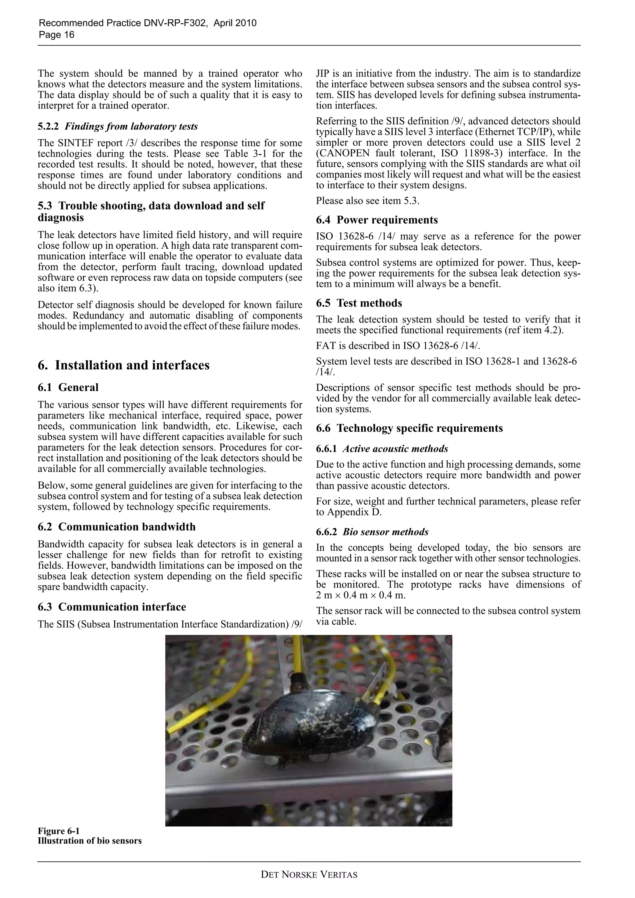
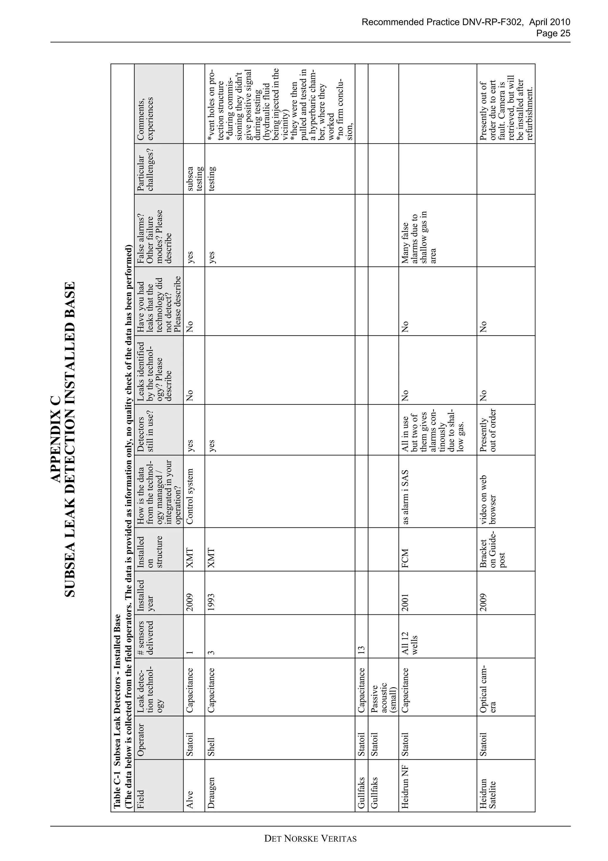
TableD-1Detectors-SupplierTechnicalData(Continued)
Tech-
nology
Calibra-
tion/
Re-cali-
bration
Mainte-
nance
Mechani-
calinter-
face
Weight
[kg]
DimensionsConnec-
tionto
power
andcom-
munica-
tion
Power
need
Band-
width
need
Maturity1Detectablerelease
limitorotheraccu-
racyinformation
Detectable
media
Detection
range
Reliabil-
itydata2
Design
life
[years]
Water
depth
[m]
Tem-
pera-
ture
[°C]](https://image.slidesharecdn.com/rp-f3022010-04-150513092724-lva1-app6891/75/Rp-f302-2010-04-34-2048.jpg)
![Recommended Practice DNV-RP-F302, April 2010
Page 35
DET NORSKE VERITAS
Note1:Thedatabelowarecollectedfromvarioussuppliersofleakdetectors.Forsomeofthetechnologies,morethanonesupplierisavailableandhavebeengivinginputtothedatabelow.Whenconsidering
aspecificproductforagivenapplication,objectiveevidenceshouldbecollectedfromthesuppliertoverifytheperformancespecificationsforthatspecificproduct.
Note2:Othersuppliersthanthosethathavegiveninputtothistablemayexist
1Maturityclassesareforthistabledefinedasfollows:Concept,ConceptTested,PrototypesorPilotstested,Commerciallydelivered,Commerciallydeliveredandqualified
2Reliabilitydatamaybecalculatedfromfieldexperiencedataormaybecalculatedbyapplyingareliabilitymodel.Inbothcases,thereliabilitydatashouldbespecificandgiveninhardnumbers
*NA=NotApplicable
TableD-1Detectors-SupplierTechnicalData(Continued)
Tech-
nology
Calibra-
tion/
Re-cali-
bration
Mainte-
nance
Mechani-
calinter-
face
Weight
[kg]
DimensionsConnec-
tionto
power
andcom-
munica-
tion
Power
need
Band-
width
need
Maturity1Detectablerelease
limitorotheraccu-
racyinformation
Detectable
media
Detection
range
Reliabil-
itydata2
Design
life
[years]
Water
depth
[m]
Tem-
pera-
ture
[°C]](https://image.slidesharecdn.com/rp-f3022010-04-150513092724-lva1-app6891/75/Rp-f302-2010-04-35-2048.jpg)