Eaa 206 s4 three hinged arch test (manual)
•
0 likes•71 views

About three-hinged arch experiment

Recommended
Recommended
More Related Content
What's hot
What's hot (20)
Similar to Eaa 206 s4 three hinged arch test (manual)
Similar to Eaa 206 s4 three hinged arch test (manual) (20)
Recently uploaded
Recently uploaded (20)
Eaa 206 s4 three hinged arch test (manual)
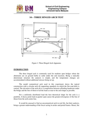
- 1. School of Civil Engineering Engineering Campus Universiti Sains Malaysia ________________________________________________________________________ 1 S4 – THREE HINGED ARCH TEST Figure 1: Three Hinged Arch Apparatus INTRODUCTION The three hinged arch is commonly used for medium span bridges where the abutments are on ground liable to settle under the end reactions. Being a statically determinate structure the analysis is simple, and the temperature changes are accommodated without additional stresses being set up. The model symmetrical arch used in this experiment shows the typical construction with a circular arch rib supporting spandrels on which the flat road deck is carried. The elevation of the arch rib is a compromise between affording headroom under the bridge and the line of thrust of all the loads as near to the arch shape as possible. For a uniformly distributed load the best theoretical shape for the arch is a parabola. A heavy point load at quarter span causes the greatest divergence of the line of thrust from the arch centre line. It would be unusual to find an unsymmetrical arch in real life, but their analysis, brings a greater understanding of the forces acting in arches and portal frames. Hence, the
- 2. School of Civil Engineering Engineering Campus Universiti Sains Malaysia ________________________________________________________________________ 2 experiment provides an opportunity to study the interaction of the horizontal and vertical reaction for an unsymmetrical three pinned structures. ACCESSORIES The complete set of accessories (Figure 1) consists of:- 1- HST.401 Short bridge section 1- HST.402 L.H. bridge section 1- HST.403 R.H. bridge section 1- HST.404 bracket assembly 1- HST.405 track plate assembly 1- HST.406 Reaction load hanger 1- HST.409 Rolling Load (50N & 25N) Optional extras 4 sets – HST.408 Uniformly Distributed Load of 25N per set. APPARATUS The model bridges are made up from cast aluminium sections hinged at the crown. The right hand section is 500mm span, 200mm rise and 725mm radius with a pair of ball bearings at the springing. The left hand section of the symmetrical arch has the same span and rise: for the unsymmetrical model it has a span of 250mm, 125mm and 312.5mm. Both left hand sections can be pinned at the springing to bracket fixed to the vertical side of the HST.1 frame. The right hand bearing runs on a horizontal track plate fitted with a true span maker and a system for applying a horizontal force toward the center of the arch. Two types of loading are available. The one consist of a set of steel bars to stimulate a uniformly distributed load. The other is a pair of a set of steel bars to stimulate a vertical load (supplied standard). OBJECTIVES A set of experiments can be carried out to investigate:- (i) The value of the horizontal thrust at the arch springing (ii) The line of thrust of the arch (iii) The influence line for the horizontal thrust (iv) The reaction locus
- 3. School of Civil Engineering Engineering Campus Universiti Sains Malaysia ________________________________________________________________________ 3 THEORY For a symmetrical three pinned arch the application of the overall conditions of equilibrium yields two equations for a vertical load as shown (Figure 2):- Moment about A P.x – VB.L = 0 Vertical Equilibrium P- VB- VA = 0 To find the horizontal thrust an extra equation can be written because the moment at C is 0. Moments about C for right hand section HBh – VB.½L = 0 It can be seen that VB is a linear function of the load position x, hence H is also a linear function of x. Figure 2 : Symmetrical Three Pinned Arch When the three pinned structure is unsymmetrical (Figure 3) the approach is the same but the solution of the equations is more complicated Moments about A P.x – VB.L + HB(hB – hA) = 0 Vertical Equilibrium P –VB – VA = 0 Moments about C for right hand section HBhB – VB.ℓB = 0
- 4. School of Civil Engineering Engineering Campus Universiti Sains Malaysia ________________________________________________________________________ 4 As before, horizontal equilibrium HA – HB = 0 For a uniformly distributed load, w over all the span of a symmetrical arch Moments about A w.L. ½ L – VB. L = 0 VB = ½wL = VA Moments about C for right hand section w.½L.¼L + HBh – VB.½L = 0 HB = wL2 / 8h Figure 3: Unsymmetrical Three Pinned Arch
- 5. School of Civil Engineering Engineering Campus Universiti Sains Malaysia ________________________________________________________________________ 5 PROCEDURE Part 1 Set up the symmetrical arch as shown in the diagram above, checking that the span is 1m. The span is measured from the left hand pin to the marker on the track plate for the right hand bearing. Add weights to the reaction load hanger to balance the self weight of the bridge, so that the axis is in line with the span marker. Treat this as the datum for the experiment. Take the 50N load and place it over the left hand springing, where it should have no effect on the horizontal reaction. Move the load hanger to restore the bridge to its true span. Repeat this across the bridge until 50N load is over the right hand springing. Join the two rolling loads 100mm apart with the coupling link provided and for two or three positions of this composite load find the horizontal reaction. Using the special distributed load bars or loose weights lay three or four different values of uniformly distributed load across the whole span and find the horizontal reaction. Part 2 Set up the unsymmetrical bridge: the left hand springing should be 177mm above bottom members of the frame, and the span is 750mm. Add weights to the reaction load hanger to balance the self weight of the bridge. Treat this as a datum for the experiment. Place the 50N load 50mm from the left hand springing and add weights to the reaction load hanger to find the value of horizontal thrust that restores the bridge to its true span. Move the load 50mm to the right and find the new reaction, repeating this until the load is at the crown pin. Then change the load movement to 100mm rightward, carry until the bridge has been transverse by the load. Join the two rolling loads with the coupling link and position the load where it is expected to cause the maximum horizontal reaction and the corresponding position of the load. By adjusting the load position and the horizontal reaction, find the maximum horizontal reaction and the corresponding position of the load. Take a uniformly distributed load 500mm long and of 50N total weight, a repeat the foregoing procedure to find the maximum horizontal reaction and the corresponding position of the uniform loading which is shorter than the span of the bridge.
- 6. School of Civil Engineering Engineering Campus Universiti Sains Malaysia ________________________________________________________________________ 6 RESULTS Plot an influence line for the experimental value of horizontal reaction on each of the bridges. Add the theoretical influence line for a 50N load crossing the bridge. Use the influence line to predict the horizontal reaction for the various loading placed on the bridges and compare them with the experimental values. For one of the composite loadings used in Part 1 , make scale drawing of the arch centre line and construct the forces diagram in a similar way to the following Figure 4 below :- Figure 4
- 7. School of Civil Engineering Engineering Campus Universiti Sains Malaysia ________________________________________________________________________ 7 S5 – DATA SHEETS CASE 1 : Symmetrical Arch Length of Arch = Height of left support = Height of right support = Height of Arch = Vertical reaction (self weight) = Point Load = Rolling Load System = Uniformly Distributed Load = Data Sheet 1 : Point Load 50 N SN Location of point load from left support Horizontal Thrust Maximum Horizontal Thrust Influence Line Ordinate 1 0 2 200 3 400 4 500 5 600 6 800 7 1000 Data Sheet 2: Rolling Load 75 N SN Location of point load from left support Horizontal Thrust Maximum Horizontal Thrust Influence Line Ordinate 1 300 2 400 3 500 Data Sheet 3: Uniformly Distributed Load 75 N/m SN Location of point load from left support Horizontal Thrust Maximum Horizontal Thrust Influence Line Ordinate 1 100 2 250 3 400
- 8. School of Civil Engineering Engineering Campus Universiti Sains Malaysia ________________________________________________________________________ 8 CASE 2 : Unsymmetrical Arch Length of Arch = Height of left support = Height of right support = Height of Arch = Vertical reaction (self weight) = Point Load = Rolling Load System = Uniformly Distributed Load = Data Sheet 1: Point Load 50 N SN Location of point load from left support Horizontal Thrust Maximum Horizontal Thrust Influence Line Ordinate 1 0 2 125 3 250 4 375 5 500 6 625 7 750 Data Sheet 2: Rolling Load 75 N SN Location of point load from left support Horizontal Thrust Maximum Horizontal Thrust Influence Line Ordinate 1 200 2 250 3 300 Data Sheet 3 : Uniformly Distributed Load 75 N/m SN Location of point load from left support Horizontal Thrust Maximum Horizontal Thrust Influence Line Ordinate 1 50 2 100 3 150