Install Infrared Switch Hands-Free Door
•
0 likes•294 views

The CM-324 is an active infrared hands-free switch that can be used to automatically open doors. It has adjustable detection range and time delay settings and can be mounted in door frames or electrical boxes. The device connects to a power source and door operator system. It operates by detecting motion with an infrared sensor and activating a relay to trigger the door opening. Installation involves running wiring, setting dip switches for operating mode, mounting the unit, and adjusting the detection range and time delay.

Recommended
More Related Content
What's hot
What's hot (20)
Similar to Install Infrared Switch Hands-Free Door
Similar to Install Infrared Switch Hands-Free Door (20)
More from JMAC Supply
More from JMAC Supply (20)
Recently uploaded
Recently uploaded (20)
Install Infrared Switch Hands-Free Door
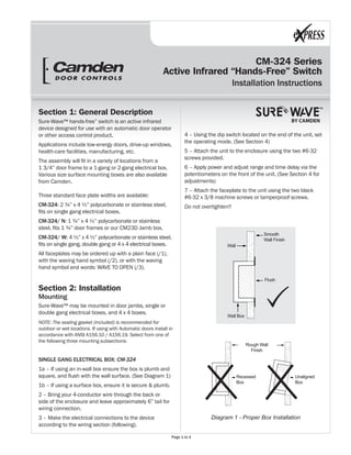
- 1. CM-324 Series Active Infrared “Hands-Free” Switch Installation Instructions BY CAMDEN Section 1: General Description Sure-Wave™ hands-free” switch is an active infrared device designed for use with an automatic door operator or other access control product. Applications include low-energy doors, drive-up windows, health-care facilities, manufacturing, etc. The assembly will fit in a variety of locations from a 1 3/4” door frame to a 1-gang or 2-gang electrical box. Various size surface mounting boxes are also available from Camden. Three standard face plate widths are available: CM-324: 2 ¾” x 4 ½” polycarbonate or stainless steel, fits on single gang electrical boxes. CM-324/ N: 1 ¾” x 4 ½” polycarbonate or stainless steel, fits 1 ¾” door frames or our CM23D Jamb box. CM-324/ W: 4 ½” x 4 ½” polycarbonate or stainless steel, fits on single gang, double gang or 4 x 4 electrical boxes. All faceplates may be ordered up with a plain face (/1), with the waving hand symbol (/2), or with the waving hand symbol and words: WAVE TO OPEN (/3). Section 2: Installation Mounting Sure-Wave™ may be mounted in door jambs, single or double gang electrical boxes, and 4 x 4 boxes. NOTE: The sealing gasket (included) is recommended for outdoor or wet locations. If using with Automatic doors install in accordance with ANSI A156.10 / A156.19. Select from one of the following three mounting subsections: SINGLE GANG ELECTRICAL BOX: CM-324 1a – If using an in-wall box ensure the box is plumb and square, and flush with the wall surface. (See Diagram 1) 1b – If using a surface box, ensure it is secure & plumb. 2 – Bring your 4-conductor wire through the back or side of the enclosure and leave approximately 6” tail for wiring connection. 3 – Make the electrical connections to the device according to the wiring section (following). 4 – Using the dip switch located on the end of the unit, set the operating mode. (See Section 4) 5 – Attach the unit to the enclosure using the two #6-32 screws provided. 6 – Apply power and adjust range and time delay via the potentiometers on the front of the unit. (See Section 4 for adjustments) 7 – Attach the faceplate to the unit using the two black #6-32 x 3/8 machine screws or tamperproof screws. Do not overtighten!! Diagram 1 - Proper Box Installation Rough Wall Finish Recessed Box Unaligned Box Wall Wall Box Flush Smooth Wall Finish Page 1 to 4
- 2. CM-324 Active Infrared “Hands-Free” Switch Installation Instructions 2-GANG (or 4x4) ELECTRICAL BOX: CM-324W 1a – If using an in-wall box ensure the box is plumb and square, and flush with the wall surface. (See Diagram 1) 1b – If using a surface box, ensure it is secure & plumb. 1c – If using a 4 x 4 box, ensure the box is plumb and square, and flush with the wall surface, then attach the metal adaptor plate (included in the CM-324W package) to the box using appropriate fasteners. 2 – Bring your 4-conductor wire through the back or side of the enclosure and leave approximately 6” tail for wiring connection. 3 – Make the electrical connections to the device according to the wiring section (following). 4 – Using the dip switch located on the end of the unit, set the operating mode. (See Section 4) 5 – Attach the unit to the enclosure using the two #6-32 screws provided. 6 – Apply power and adjust range and time delay via the potentiometers on the front of the unit. (See Section 4 for adjustments) 7 – Attach the faceplate to the unit using the two black #6-32 x 3/8 machine screws or tamperproof screws. Do not overtighten!! DOOR FRAME: CM-324N 1a – If mounting directly in a 1¾” wide aluminum jamb, make a cutout in the door frame at the intended location as per Diagram 2. (See Diagram 2 on page 4) Drill and tap two mounting holes as shown. 1b – If mounting the unit in our CM-23d deep jamb box, first mount the jamb box according to the instructions packaged with the enclosure. Using the CM-23D as a guide, drill a wire access hole through the jamb to fish the wiring through. 2 – Bring your 4-conductor wire through the back or side of the enclosure (or Jamb) and leave approximately 6” tail for wiring connection. 3 – Make the electrical connections to the device according to the wiring section (following). 4 – Using the dip switch located on the end of the unit, set the operating mode. (See Section 4) 5 – Attach the unit to the enclosure or jamb using the two #6-32 screws provided. 6 – Apply power and adjust range and time delay via the potentiometers on the front of the unit. (See Section 4 for adjustments) 7 – Attach the faceplate to the unit using the two black #6-32 x 3/8 machine screws or tamperproof screws. Do not overtighten!! Wiring CAUTION: Do not apply power to the unit until all second- ary wiring is complete, and dip-switches have been set. The CM-324 can be powered from 12 or 24 volts, AC or DC. Connect the two Red wires, (which are non-polarity sensitive) to the power source. The output is a form C relay. N.O is Blue, N.C. is Violet, and Common is Green. Selecting the correct output is also dependant on the operating mode chosen. (See Section 4) Most applications will utilize the N.O. and Common terminals. Section 3: Applications & Set-up Applications See Diagram 3 for the location of the Dip switches. Switch 1 – Normal Mode/Fail-Safe Mode Choose Normal Mode if you wish the N.O. contact to remain open if the power were to fail. This is the factory setting. Choose Fail-safe Mode if you wish the contacts to close upon power fail. Move the Dip switch to OFF position, and wire your device to the Common and N.C. wires. Switch 2 – Time Delay Mode/Toggle Mode Factory setting is Time Delay (Sense) mode, whereby the contact closure will be adjustable from 1 – 5 seconds using the Time Delay Potentiometer. In Toggle (or Switch) mode, when the CM-324 is activated once, the relay will stay energized until it is activated once again. (The adjustable timer is inactive in this mode) Photo Eye Red LED Time Delay Adjustment Dip Switch Red Red Blue Green Violet 12-24V Power N.O. OM N.C. Range Adjustment Wiring Pigtail CM-324 Diagram 3 - Location of Adjustments Page 2 to 4
- 3. CM-324 Active Infrared “Hands-Free” Switch Installation Instructions Switch 3 – LED On/LED Off This switch disables the LED, should this feature be desired. Factory setting is ON. Once the Dip switches have been set, and the unit is installed in the frame or enclosure, apply power to the unit and observe operation. Set both potentiometers to minimum setting initially (fully counter-clockwise). See Diagram 3 for location. Adjust the range potentiometer by turning the pot in a clockwise manner, and passing your hand in front of the unit. Rotate the pot until the desired range is obtained. See Diagram 4 for patterns. Next, adjust the time delay potentiometer by turning clockwise until the desired time delay is obtained. It is sometimes beneficial to leave this adjustment set to minimum and utilize the time delay on the door operator, if present. NOTE: Timer is non-functional in Toggle Mode. Install the faceplate using the screws provided. Do not overtighten!! OPTIONAL – Apply the included Wheelchair logo to the frame or wall at desired location. See Diagram 5 on page 4. Do not apply directly to the faceplate!! If using this product with an Automatic Door, proceed to Section 4 for System Inspection Instructions. Section 4: System Inspection Instructions After the Installation and operational check of the system: 1. Place warning label on the door (as per ANSI A156.10 or A156.19 guidelines). This will advise the person entering the swing side zone that the door will move. 2. Instruct the owner on door system operation and how to test it. This should be checked on a daily basis. 3. Instruct the owner on what to do if the door or any of its components become damaged. 4. Strongly recommend to the owner that the complete entry be inspected twice a year as part of the service agreement. Section 5: Technical Data Section 6: Warranty Camden Door Controls guarantees the Sure-Wave™ to be free from manufacturing defects for 3 years from date of sale. If during the first 3 years the CM-324 fails to perform correctly, it may be returned to our factory where it will be repaired or replaced (at our discretion) without charge. Except as stated herein, Camden extends no warranties expressed or implied regarding function, performance or service. Model CM-324 Body Size 4” L x 1” W x 1 ½” Deep Mounting 2 x #6-32 MS Faceplates Sizes Jamb, 1-gang, & 2-gang Technology Infra-Red with Coded Modulated Carrier Security Automatic Self-changing ID Operating Modes Pulse (sense) / Toggle Operating Temp -4 to +153 ºF (-20 to +85 ºC) Operating Voltage 12-24 Volts, AC/DC ± 12% Current Draw 50 - 60 mA. Response Time 100 ms. Activation Range: Minimum Maximum 1” – 3” 1” – 26” Relay Output Form C (SPDT) Relay Contact Rating 5 amps @ 30 VDC Output Type Normal or Fail-Safe Connections 11” 22 AWG Leads Time Delay 1 to 5 Seconds Electrical Life 100,000 Operations@ Rated Capacity 500,000 Operations@ ½ Rated Capacity Door Frame 25mm 1" CM-324/N3 Questions? Call us toll-free at 1-877-226-3369 Diagram 4 Wheelchair Sticker Placement Page 3 to 4
- 4. DISCOVER THE BEST IN DOOR ACTIVATING AND LOCKING PRODUCTS! www.camdencontrols.com Toll Free: 1.877.226.3369 Push Buttons Key Pads Strikes Magnetic Locks Key Switches Relays & Timers Access Control CM-324 Active Infrared “Hands-Free” Switch Installation Instructions CM-324-Rev1 Revised: 03/18/2011 2:30 PM Part No: 40-82B100 Diagram 2 Jamb Cutout Dimensions 1’0’ 2’ 3’ 3” (75mm) 26” (660mm) Diagram 5 Adjustable Range Settings 73mm 7/8"2 32mm 1/4"1 83mm 9/32"3 Drill & Tap 6-32 (2 holes) Page 4 to 4