young call girls in Khanpur,🔝 9953056974 🔝 escort Service
Configure alarm widget and rules
1. 15 Configure your alarm widget and automation rules with the newly
added functionality!
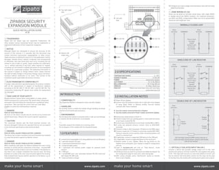
3.1 ZONE WIRING (Z1-Z6)
Zones can be wired as normally closed loops, with single (SEOL)
or double end-of-line (DEOL) resistors. For maximum protection,
use SEOL and DEOL configurations. Make sure not to exceed 400m
maximum wire length per zone.
NORMALLY CLOSED LOOP
Zone
terminal COMMON
Zone
terminal COMMON
One or more
normally
closed
contacts with
no end-of-
line resistor
SINGLE END-OF-LINE RESISTOR
Zone
terminal COMMON
Zone
terminal COMMON
One or more
normally
closed
contacts and
one or more
normally
opened
contacts with
end-of-line
resistor
DOUBLE END-OF-LINE RESISTOR
Zone
terminal COMMON
Tamper
contact
Tamper
contact
Alarm
contact
One normally closed ALARM contact and one or
more normally closed tamper contacts with double
end-of-line resistor
3.2 OPTICALLY ISOLATED INPUT (IN+/IN-)
Connect a device that provides voltage output of 8-14 VDC, with
positive wire going to terminal marked IN+ and negative wire going
to IN-. This input will consume no more than 40mA of current, and
has an internal 1kΩ termination resistor (so this input can be used
to interface Security module with existing alarm panel siren output).
make your home smart www.zipato.com make your home smart www.zipato.com
TRADEMARKS
Zipato and the Zipato logo are registered Trademarks. All
other product names mentioned herein may be trademarks or
registered trademarks of their respective companies.
NOTICE
Although Zipato has attempted to ensure the accuracy of the
content of this manual, it is possible that this document may
contain technical inaccuracies, typographical, or other errors.
Zipato assumes no liability for any error in this publication, and for
damages, whether direct, indirect, incidental, and consequential
or otherwise, that may result from such error, including, but not
limited to loss of data or profits. Zipato provides this publication
“as is” without warranty of any kind, either express or implied,
including, but not limited to implied warranties of merchantability
or fitness for a particular purpose. The published information in
the manual is subject to change without notice. Zipato reserves
the right to make changes in the product design, layout, and driver
revisions without notification to its users. This version of the
Installation guide supersedes all previous versions.
ELECTROMAGNETIC COMPATIBILITY
In proper state and when operated properly, the product complies
with all the requirements in respect of interference radiation
according to EN 301 489-17, EN 301 489-1 and EN 300 328. The
connections conducting HF signals must neither be manipulated
nor damaged.
TAKE CARE OF YOUR SAFETY
Display extreme caution when using ladders or steps, please
follow manufacturer’s instructions. Be careful when using hand
and power tools and follow the manufacturer’s guidelines when
using them. Take care that the correct tools are used. Wear
goggles or protective clothing where required.
DANGER
RISK OF ELECTROCUTION
All work on the device should only be carried out by trained and
skilled electricians. Observe the country-specific regulations.
CAUTION
The connected devices and the flush-mounted receiver can
become damaged if devices are operated that do not correspond
to the technical specifications (see technical data).
DANGER
RISK OF FATAL INJURY FROM ELECTRIC CURRENT.
The device has no basic insulation and must therefore be installed
in a way that protects against accidental contact.
DANGER
RISK OF FATAL INJURY FROM ELECTRIC CURRENT.
When installing a wall plate, the distance between the cover’s fixing
brackets or screws and the connections of the flush - mounted MM
Switch Single must be at least 4 mm once installed. If the distance is
less than 4 mm, a deeper installation box must be used. The fixing
brackets or screws of the cover must not press against the housing.
Only insulated tools may be used for operation on the device, e.g. an
insulated phase tester.
2.0 SPECIFICATIONS
TEMPERATURE RANGE 0 - 50ºC
HUMIDITY RANGE 0-95% RH
POWER powered by Zipabox
AUX POWER 10-14 VDC 800mA
BELL/SIREN OUT 10-14 VDC 600 mA
SIREN IN 8-14VDC, 20mA max
PGM OUT 150mA max solid state relay with selectable
active level (see 3.5)
3.0 INSTALLATION NOTES
01 Power off you Zipabox
02 Connect security module to either left or right side of the Zipabox
(if using Zipato Power or Backup module, Security module
connects after those modules).
Security module connected directly to Zipabox
Security module connected to Power module connected to Zipabox
03 Connect your wired sensors to Zone1-6.
04 Connect output from you existing panel or some external sensor
to terminals marked IN+/IN-.
05 Connect your wired bell/siren to terminals marked BELL+/BELL.
06 If using any powered sensors, connect them to AUX+/AUX-
terminals.
07 Connect a relay or other low power 12V device to the PGM output.
08 Connect a lead acid, 12 V battery to terminals marked BAT+/BAT.
Failing to observe correct polarity while connecting battery will
result in a shorted fuse!
09 If applicable, connect a supported USB device to the USB port.
10 If applicable, connect a supported device to the serial port.
11 Restore power to your Zipabox. When the top button on the
Zipabox turns solid green, your module is ready for configuration
and use.
12 Login to my.zipato.com and click on “Total devices”, locate
Security module in the drop-down list.
13 Unhide all zones you wish to use (zones are hidden by default). On
the configuration page for each zone, select wiring type.
14 After saving changes, press “Synchronize” button to transfer
them to your Zipabox.
INTRODUCTION
COMPATIBILITY
This Expansion Module is designed to work only with Zipabox.
HANDLING
Do not drop, knock or shake the module. Rough handling can break
internal circuit boards and connectors.
ENVIRONMENT
Do not expose the module to excessive heat or cold, as it can damage
or shorten the life of electronic circuit boards.
If possible, dispose this module at a recycling center.
Do not dispose of this module with the household waste.
1.0 FEATURES
6 wired zones (expandable to 24 using additional Security Modules)
1 optically isolated 12V input
1 supervised wired bell/siren output
1 programmable output
1 supervised 12V auxiliary power supply for powered wired
sensors
1 USB port
1 serial/UART port, user selectable between RS-232 mode and
half-duplex RS-485 mode
1 lead acid battery charger
ZIPABOX SECURITY
EXPANSION MODULE
QUICK INSTALLATION GUIDE
v1.0
Bottom left
angle view
Top right angle
view
Left side
view
1 RS-232-RX
4 RS-485-B
5 COM
54321
2 RS-232-TX
3 RS-485-A
2. make your home smart www.zipato.com make your home smart www.zipato.com
3.3 SUPERVISED BELL/SIREN OUTPUT
Bell output will supply 600mA of current at 12VDC. The output is
supervised and power limited. If unused, connect a 1kΩ termination
resistor to across BELL+ and BELL- terminals to prevent tamper
event generation. Bell output is protected from over-current by an
electronic fuse.
3.4 AUX POWER OUTPUT
For powering wired sensors that require 12VDC, connect respective
wires to the AUX+ and AUX- power terminals. Output is monitored
for short circuit and current limited. All devices connected to these
terminals should not draw more than 800mA of current. While
operating on battery, voltage output will vary between 10 and 14
VDC. AUX and BELL terminals share the same protection device,
so an over-current or short circuit condition on AUX terminals will
also render BELL output inoperable (two tamper events will be
generated).
3.5 PROGRAMMABLE (PGM) OUTPUT
PGM output is a single-pole, normally open solid state relay output.
Maximum current is 150mA – for larger currents an external relay
is required. Maximum allowed voltage is 24VDC / Vrms. Maximum
on-state resistance is 8Ω. PGM output default setting is switching
to GND when activated. It can be also configured to switch to AUX+
voltage level by changing the built-in jumper position. To change the
jumper position, follow this procedure:
1 power-off your Zipabox
2 remove any wires connected to Z, IN, BAT, AUX, BELL, PGM or
COM terminals
3 remove any modules connected to Security module (including
Zipabox)
4 locate two screws on the underside of the Security module and
unscrew them
5 while holding the underside of the security module in one hand,
press lightly on the longer side of the module topside and carefully
slide the topside of the module off
6 locate the jumper cap on the top board of the module and adjust
it accordingly
7 slide the top cover back onto the module, carefully align both sides
of the case and gently press them together to close the gap
8 reverse actions from steps 4 to step 1
Figure 1 – Jumper cap positions
4.1 SYSTEM FAILURES
This system has been carefully designed to be as effective as
possible. There are circumstances, however, involving fire, burglary,
or other types of emergencies where it may not provide protection.
Any alarm system of any type may be compromised deliberately or
may fail to operate as expected for a variety of reasons. Some but not
all of these reasons may be:
4.2 INADEQUATE INSTALLATION
A security system must be installed properly in order to provide
adequate protection. Every installation should be evaluated by a
security professional to ensure that all access points and areas are
covered. Locks and latches on windows and doors must be secure
and operate as intended. Windows, doors, walls, ceilings and other
building materials must be of sufficient strength and construction to
provide the level of protection expected. A reevaluation must be done
during and after any construction activity.
4.3 CRIMINAL KNOWLEDGE
This system contains security features which were known to be
effective at the time of manufacture. It is possible for persons with
criminal intent to develop techniques which reduce the effectiveness
of these features. It is important that a security system be reviewed
periodically to ensure that its features remain effective and that
it be updated or replaced if it is found that it does not provide the
protection expected.
4.4 ACCESS BY INTRUDERS
Intruders may enter through an unprotected access point,
circumvent a sensing device, evade detection by moving through
an area of insufficient coverage, disconnect a warning device, or
interfere with or prevent the proper operation of the system.
4.5 POWER FAILURE
Control units, intrusion detectors, smoke detectors and many
other security devices require an adequate power supply for proper
operation. If a device operates from batteries, it is possible for the
3.6 BATTERY
To achieve power standby times, connect a sealed, rechargeable lead
acid or gel type battery to terminals marked BAT+ and BAT. Failure to
observe correct polarity will result in a burnt fuse! Security module
charges the battery with maximum of 400 mA, float voltage is 13.5-
13.8 VDC. Standby duration times will depend on battery capacity and
number of powered devices connected to AUX terminals, and also
on other devices connected to other Zipabox modules. Minimum
recommended battery capacity is 4Ah, and if no powered sensors
or USB devices are connected to Zipabox, this battery will provide 12
hour standby. Battery capacity will deteriorate with age and number of
charge/discharge cycles, so it’s recommended to replace the battery
every 3-5 years. Battery terminals are protected against reverse
polarity with a diode crowbar circuit, and reversing the battery polarity
will DESTROY the fuse. In order to restore battery functionality, fuse
will need to be replaced. Procedure to replace the fuse:
1 obtain a good quality mini blade automotive fuse rated for 3A or 5A,
such as Littelfuse 0297003.WXNV
2 remove any wires connected to Z, IN, BAT, AUX, BELL, PGM or
COM terminals
3 remove any modules connected to Security module (including
Zipabox)
4 locate two screws on the underside of the Security module and
unscrew them
5 while holding the underside of the security module in one hand,
press lightly on the longer side of the module topside and carefully
slide the topside of the module off
6 remove the PCB assembly from plastic casing
7 holding the lower PCB, carefully pull the upper PCB upwards
8 locate the fuse on the underside of the PCB, remove the old fuse
from the holder and replace it with a new one
9 reverse actions from steps 7 to step 1
Figure 2 – Underside of the top PCB
3.7 SERIAL PORT
Security module features an UART port, which can be configured to
be either RS-232 or RS-485. RS-232 mode is supported in 3-wire
mode (no hardware flow control). RS-485 is supported in a two-wire,
half duplex mode. Bus biasing (680Ω) and termination (120Ω) is built-
in. If using port in RS-232 mode, connect your equipment to ports
marked RS-232-TX, RS-232-RX and GND. If using port in RS-485
mode, connect your equipment to terminals marked RS-485-A, RS-
485-B and GND (if applicable).
Use only 26-20AWG / 1.5mm2
wire and strip 9-11 mm of insulation
prior to inserting wire. To insert wire, gently push orange tab, insert
stripped wire end and then release tab. To select active mode of
the serial port, login to my.zipato.com and click on “Total devices”,
locate “Security module” in the drop-down list and click on it. On
the left pane, select tab “Configuration”. Select appropriate mode
for the serial port, click “Save” and close the “Devices” window.
Click “Synchronize” to transfer the settings to your Zipabox.
4.0 NOTE TO INSTALLERS
This warning contains vital information. As the only individual in
contact with system users, it is your responsibility to bring each item
in this warning to the attention of the users of this system.
batteries to fail. Even if the batteries have not failed, they must be
charged, in good condition and installed correctly. If a device operates
only by AC power, any interruption, however brief, will render that
device inoperative while it does not have power. Power interruptions
of any length are often accompanied by voltage fluctuations which
may damage electronic equipment such as a security system. After
a power interruption has occurred, immediately conduct a complete
system test to ensure that the system operates as intended.
4.6 FAILURE OF REPLACEABLE BATTERIES
For wireless sensors the expected battery life is a function of the
device environment, usage and type. Ambient conditions such as
high humidity, high or low temperatures, or large temperature
fluctuations may reduce the expected battery life. While each
transmitting device has a low battery monitor which identifies when
the batteries need to be replaced, this monitor may fail to operate as
expected. Regular testing and maintenance will keep the system in
good operating condition.
4.7 COMPROMISE OF RADIO FREQUENCY
(WIRELESS) DEVICES
Signals may not reach the receiver under all circumstances which
could include metal objects placed on or near the radio path or
deliberate jamming or other inadvertent radio signal interference.
4.8 SYSTEM USERS
A user may not be able to operate a panic or emergency switch
possibly due to permanent or temporary physical disability, inability
to reach the device in time, or unfamiliarity with the correct
operation. It is important that all system users be trained in the
correct operation of the alarm system and that they know how to
respond when the system indicates an alarm.
4.9 SMOKE DETECTORS
Smoke detectors that are a part of this system may not properly alert
occupants of a fire for a number of reasons, some of which follow:
The smoke detectors may have been improperly installed or
positioned.
Smoke may not be able to reach the smoke detectors, such as
when the fire is in a chimney, walls or roofs, or on the other side
of closed doors.
Smoke detectors may not detect smoke from fires on another
level of the residence or building.
Every fire is different in the amount of smoke produced and the
rate of burning. Smoke detectors cannot sense all types of fires
equally well.
Smoke detectors may not provide timely warning of fires caused
by carelessness or safety hazards such as smoking in bed, violent
explosions, escaping gas, improper storage of flammable
materials, overloaded electrical circuits, children playing with
matches or arson.
Even if the smoke detector operates as intended, there may be
circumstances when there is insufficient warning to allow all
occupants to escape in time to avoid injury or death.
4.10 MOTION DETECTORS
Motion detectors can only detect motion within the designated
areas as shown in their respective installation instructions. They
cannot discriminate between intruders and intended occupants.
Motion detectors do not provide volumetric area protection. They
have multiple beams of detection and motion can only be detected
in unobstructed areas covered by these beams. They cannot detect
motion which occurs behind walls, ceilings, floor, closed doors, glass
partitions, glass doors or windows. Any type of tampering whether
intentional or unintentional such as masking, painting, or spraying of
any material on the lenses, mirrors, windows or any other part of the
detection system will impair its proper operation. Passive infrared
motion detectors operate by sensing changes in temperature.
However their effectiveness can be reduced when the ambient
temperature rises near or above body temperature or if there are
intentional or unintentional sources of heat in or near the detection
area. Some of these heat sources could be heaters, radiators, stoves,
barbecues, fireplaces, sunlight, steam vents, lighting and so on.
ZIPABOX SECURITY
EXPANSION MODULE
QUICK INSTALLATION GUIDE
v1.0
Top
view
Bottom
view
Position 1 (default):
PGM switches to GND
Position 2:
switches to AUX+
Fuse inserted into fuse holder