SlideShare a Scribd company logo
1 of 32
Download to read offline
FIELD DEVICES – ***POSITIONERS***
Product Specifications
08.2018 PSS EVE0105 A-(en)
SRD991 Intelligent Positioner with HART, PROFIBUS-PA,
FOUNDATION Fieldbus H1 or Without Communication
DEVICE FEATURES
Intelligent
• Auto-start with self-calibration
• Self diagnostics, status- and diagnostic messages
• Easy operation with three key pads
• Multi-Lingual full text graphical LCD
• VALcare™ or Valve Monitor DTM
for valve diagnostics and predictive maintenance
With communication
• HART, FOUNDATION Fieldbus H1,
PROFIBUS-PA
• Configuration by means of local keys, hand-
held terminal (HART), PC with FDT-DTM or
I/A Series system
Without communication
• Input signal 4 to 20 mA
COMMON FEATURES
• Stroke 8 to 260 mm (0.3 to 10.2 in) with
standard lever; larger stroke with special lever
• Angle range up to 95°(up to 300°as option)
• Supply air pressure up to 6 bar (90 psig),
with spool valve up to 7 bar (105 psig)
• Single or double-acting
• Mounting on linear actuators according to NAMUR
– IEC 50534-6-1 – VDI/VDE 3847
• Mounting on rotary actuators acc. to VDI/VDE 3845
or IEC60534-6-2
• Protection class IP 66 and NEMA 4X
• Approved for SIL applications
• Explosion protection: Intrinsic safety according to
ATEX / IECEx, FM, CSA, INMETRO, NEPSI,
EAC, and more
The intelligent positioner SRD991 is designed to operate pneumatic valve actuators and can be operated from control
systems (e.g. the Foxboro I/A Series System), controllers or PC-based configuration- and operational tools such as
FDT/DTM Software. The positioner is available with different communication protocols. The multi lingual full text graphical
LCD in connection with the 3 push buttons allows a comfortable and easy local configuration and operation. For
installations in contact with explosive atmospheres, certificates are available.
Equipment should be installed,operated,serviced,and maintained
only by qualified personnel.
No responsibility is assumed by Schneider Electric for any
consequences arising from the use of this material.
PSS EVE0105 A-(en)
Page 2
Contents Page
• Special Versions of SRD991................................4
Common technical data for all basic devices ...5
• Operation, Diagnostics, Service plug...................6
• Electrical classification.........................................9
Extended technical data for basic devices:
• With communication HART................................10
• With communication PROFIBUS
or FOUNDATION Fieldbus.................................11
• Basic device without communication (4-20 mA) 12
Additional equipment for basic devices ..........13
(built into the basic device)
• Pressure sensors for premium diagnostics........13
One Option board with additional inputs / outputs:
• 2 Binary inputs or ..............................................14
• 2 Binary outputs or............................................15
• 2 Binary in/outputs or........................................16
• Position feedback and Alarm or........................17
• Entry for remote Potentiometer..........................18
Additional built-in
• Limit signal switch ..............................................19
Contents Page
FUNCTIONAL DESIGNATIONS......................... 21
MODEL CODES SRD991 ................................... 22
ACCESSORIES for mounting to the positioner:
• Booster • Manifolds • Gauge manifolds........... 24
ATTACHMENT to actuators................................ 27
DIMENSIONS...................................................... 31
Option boards
"Additional i/o"
Service
plug
Cable glands
Electronics version:
Communication HART, PROFIBUS PA, FOUNDATION Fieldbus
or "Without Communication"
Limit signal
switch Pressure
sensors
Manifold Booster
G 1/4
CONTENTS SRD991
PSS EVE0105 A-(en)
Page 3
OVERVIEW
The SRD991 consists of a basic device with a digital controller that supports different communication
protocols (or also simply 4-20 mA input). Into this basic device, additional equipment can be built such as
plug-in cards for electrical input/output signals, position feedback and pressure sensors.
The pneumatic part is available in different versions (single / double acting or spool valve). For very large
actuators, boosters with increased air capacity can be flanged on. Also, different manifolds for connection of
gauges can be flanged on. For the pneumatic screw connections, we offer different threads in the housing
and adapters.
For use in hazardous areas, there are approvals according to ATEX / IECEx, FM, CSA, EAC, NEPSI, etc.
The device can be configured locally by means of push buttons and LCD / LED, or with PC + EDC82
Modem connected to the service plug of the SRD991. By means of communication, the device can be
configured remotely via FDT/DTM.
A large variety of attachment kits for all common valves and actuators are available. The list
“AttachmentKits.pdf” is updated continuously and can be found on the Internet.
For high temperature or high vibration application, we recommend to mount the SRD991 remotely and not
directly on the valve. For this, use the potentiometer unit (like the SRI990 - TXQxxxxx - H).
Please consult TI EVE0105 R for specifications.
To ensure the high performance of the positioner, we offer Advanced Diagnostics and Premium Diagnostics utilities:
Premium Diagnostics Advanced Diagnostics
Autostart Yes Yes
Custom Characterization Yes Yes
Auto diagnostic Yes Yes
Alarm Management Yes Yes
Alarm Output for Switching (with Option board) Yes Yes
Status List acc. NE107 Yes Yes
Position History Yes Yes
Response History Yes Yes
On Line Friction Yes
Stepping Signature Yes
Ramping Signature Yes
Sensitivity Signature Yes
Valve Signature Yes
PST (Partial Stroke Test) Yes
PST Predictive Maintenance Yes
Additional equipment, built into the basic device:
Option Board “2 Binary Inputs” or B
2 external switches (supplied by SRD) release a control function in the
SRD, e.g. "close valve" (configurable)
Option Board “2 Binary Inputs/Outputs” or E
2 channels, each configurable as an input or output
(to be supplied externally)
Option Board “Position Feedback” F
1 output 4-20 mA (to be supplied externally) gives stroke / angle of
rotation; 1 alarm output becomes active with a configurable event
Limit switch
T,U,
R,V
Supplies NAMUR signals when exceeding or falling below of two limit
values. Inductive sensors, independent of the controller,
in normal or safety version or three-wire, or micro switches
D Entry for remote potentiometer of external potentiometer unit
Pressure sensors
2 sensors measure the pressure of supply air and output y1 for
Premium Diagnostics; the values are passed on via communication
LCD
Full text graphic LCD in 3 languages
Accessories like Manifolds and Boosters see page 24.
SRD991 OVERVIEW
PSS EVE0105 A-(en)
Page 4
3 0 0 °
Special Versions of SRD991:
SRD991 Stainless Steel Housing
To be order with model code SRD991-xxxxxxxx-Zxxx
Please consult TI EVE0105 INOX for specifications.
For dimensional drawings see page 33.
SRD991 for Top Mounting onto small actuators
This version is designed for direct mounting on top of
small actuators without yoke - solution for actuators up
to 50 mm stroke.
Instead of the rotary potentiometer, a linear pot is used
that feeds back the actual position of the actuator.
The Model Code of this basic device is
SRD991- ............. -W
The adapter part is dependent on the manufacturer
and type of actuator and can be ordered under the
code EBZG-TMxx.
Please consult TI EVE0105 TM for specifications.
SRD991 designated for PST (Partial Stroke
Test for Emergency Shut Down)
Final control elements in Emergency Shutdown (ESD)
applications such as ON-OFF-, Blow Down and Venting
valves remain in one position over a long time without
any mechanical movement. These valves can show a
tendency to get stuck and as a result might not operate
upon demand. This can have a severe impact on the
functionality of a Safety System and could result in an
adverse condition to the operating personnel, plant
equipment and the environment. The Partial Stroke
Test (PST) offers operators a tool to identify the
troubleshooting function of ESD valves. The test can be
easily executed via the FDT-DTM based configuration
diagnostic tool VALcare™/Valve Monitor.
Please consult TI EVE0105 PST.
SRD991 for actuator with rotation up to 300°
This special version of the SRD991 is designed to be
mounted by means of standard attachment kit (like the
EBZG-R) onto rotary actuator with rotation up to 300°
.
This special version is made of a standard SRD991
with special gears.
To be ordered under Options -J.
Please consult TI EVE0105 LR.
SPECIAL VERSIONS OF SRD991
PSS EVE0105 A-(en)
Page 5
Travel range
Stroke range . . . . . . . . . . . . 8 to 260 mm (0.3 to 10.2 in)
with standard feedback levers; special levers on request
Rotation angle range . . . . . . up to 95°without mechanical
stop; up to 300°with Option –J.
Supply
Supply air pressure . . . . . . . 1.4 to 6 bar (20 to 90 psig)
with spool valve
1)
. . . . . . 1.4 to 7 bar (20 to 105 psig)
Output to actuator . . . . . . . . 0 to ~100 % of supply air
pressure (up to 5.5 bar at 6 bar supply air pressure)
with spool valve heavy duty2)
: 4 to 10 bar
Air supply. . . . . . . . . . . . . . . according to ISO 8573-1
- Solid particle size and density class 2
- Oil rate. . . . . . . . . . . . . . . class 3
- Pressure dew point 10 K under ambient temperature
The use of filter regulator for air supply of positioner is
strongly recommended. It reduces the air pressure to
actuator’s maximum pressure and keeps it constant.
For supply with Natural Gas instead of compressed air
please consult TI EVE0105 G.
Air output ln/h (scfh)
at max. deviation, single and double acting:
Supply air
pressure bar
(psig)
1.4
(20)
3
(45)
6
(90)
Standard
Amplifier
2 700
(95)
5 000
(177)
7 500
(265)
with Spool
Valve 1)
6 000
(211)
12 000
(423)
18 000
(636)
“Heavy duty” spool valve
2)
is able to deliver up to 55,000
ln/h at 10 bar. Please consult TI EVE0105 INOX.
Note: The use of boosters in connection with Spool valve
is not recommended.
Air consumption (steady state) ln/h (scfh)
Supply air
pressure
bar (psig)
1.4
(20)
3
(45)
6
(90)
single
acting
80
(2.8)
130
(4.6)
220
(7.8)
double
acting
130
(4.6)
230
(8.1)
430
(15.2)
Spool
Valve
100
(3.5)
240
(8.5)
500
(17.7)
Response characteristic 3) 4)
Sensitivity . . . . . . . . . . . . . . < 0.1 % of travel span
Non-linearity (terminal
based adjustment) . . . . . . . . < 0.4 % of travel span
Hysteresis . . . . . . . . . . . . . . < 0.3 % of travel span
Supply air dependence. . . . . < 0.1 % / 1 bar (15 psi)
Temperature effect. . . . . . . . < 0.3 % / 10 K
Mechanical vibration
10 to 60 Hz up to 0.14 mm,
60 to 500 Hz up to 2 g . . . . . < 0.25 % of travel span
Volume Booster Series (to order as accessory)
For large actuators or to reduce action time, a volume
booster may be necessary.
VBS200 / VBS201 / VBS202
Volume booster with Cv 2 and pneumatic connection 1/2”,
for direct side mounting to positioner, remote mounting, or
mounting acc. to VDI/VDE 3845
For more information please consult PSS EVE0602.
VBS300 / VBS310
Volume boosters with Cv7 and pneumatic connection 1’’,
for remote mounting
VBS300 in Aluminum, VBS310 in Stainless Steel 316
For more information please consult PSS EVE0603.
1) Spool valve is the type of amplifier used in device SRD991-Cxxxxx-S
2) Spool valve heavy duty is the amplifier used in stainless steel version
SRD991 - Cxx... - SZK
3) Data measured according to VDI/VDE 2177
4) With stroke 30 mm and lever length 90mm
FUNCTIONAL SPECIFICATIONS (common data for all versions)
SRD991 FUNCTIONAL SPECIFICATIONS
PSS EVE0105 A-(en)
Page 6
Features
Automatic start-up . . . . . . . (Autostart functionality)
Automatic determination of the mechanical end positions of
the valve (initial value and final value), IP motor parameters,
direction of action of the spring and control parameters.
The control parameters are optimized dynamically during
this routine.
This procedure makes a perfect adjustment and optimiza-
tion to the actuator possible without additional manual
settings! Several autostart modes are available (details see
on next page).
Options
• Built-in independent inductive limit switches
• Pressure sensors for monitoring of air supply and out-
put pressure I (y1)
• Additional inputs / outputs:
• Position feedback 4-20 mA + binary alarm
output, to be supplied external
• 2 binary outputs (position alarms)
• 2 binary inputs, to be supplied external
• 2 contact inputs, internal supplied
• 2 binary in-/outputs, to be supplied external
Operation and Configuration
The local LCD enables a fast and easy configuration as well
as diagnostic.
Local . . . . . . . . . . . . . . . . . . with local key pads
Display. . . . . . . . . . . . . . . . . Multi-lingual Graphic LCD,
some versions with 5 LEDs
The positioner in the version with LCD contains three
different menu languages. Standard menu languages:
- English
- German
Freely selectable third language:
- French - Portuguese - Spanish
- Italian - Swedish - and more
(further menu languages see Model Code page 23).
The third menu language has to be selected and specified
with the order, otherwise standard: French.
The third, freely selectable menu language can be modified
to another language by means of the VALcare™ DTM.
2)
The additional languages can be downloaded from our
homepage.
Diagnostics
– in the field:
• Status and Diagnostic messages via LCD
– via VALcare™ or Valve Monitor DTM
4)
:
• Service Management for planning and scheduling of
service intervals
• Histograms for displaying the position- and response-
history over time
• Partial Stroke Test for the functional inspection of safety
related actuators
• Hours in operation, cycle counter and travel sum of the
actuator are determined
• Surveillance of loop current
• Shows condition of device:
-Potentiometer
-IP Motor
-Exceeding range of actuator (possible indication for wear
of plug or seat)
-Remaining control deviation (possible indication for jam-
med actuator, blocked valve stem or plug, insufficient air
capacity / supply air pressure / positioning pressure)
• If equipped with pressure sensors (optional, see page 3):
• Monitoring of the stem friction
• Histograms for displaying the friction-history over time
• Surveillance of air supply and output pressure, each with
display of physical value
• Additional diagnostically possibilities in control operation by
means of external sensors (optional).
See also the VALcare™ Documentation.
Service plug
All basic devices are equipped with a service plug A at the
front side. There via RS232 interface a PC with VALcare
(DTM) can be connected via modem EDC82 (galv. separa-
ted, not Ex).
Information about EDC82 modem see TI EVE0102 Y.
2) With the versions “Intelligent without communication” this is
only possible with modem EDC82
3) By means of “Additional inputs / outputs”
4) For the SRD991 without communication the use of the service plug is
necessary to have access at the diagnostic with DTM
FUNCTIONAL SPECIFICATIONS (common data for all versions)
A
FUNCTIONAL SPECIFICATIONS SRD991
PSS EVE0105 A-(en)
Page 7
Manual local and remote settings:
Actuator mode . . . . . . . . . . . linear or rotary actuator
Linear valve . . . . . . . . . . . left or right mounted
Rotary actuator. . . . . . . . . opening clockwise or
counter-clockwise
Characteristic of set point . . . linear, equal percentage,
inverse-equal percentage
or custom (22 points)
Valve function . . . . . . . . . . . opens or closes with
increasing set point
Split range . . . . . . . . . . . . . free upper and lower values
Travel limits . . . . . . . . . . . . . free upper and lower values
Cutoffs. . . . . . . . . . . . . . . . . free upper and lower values
Stroke range . . . . . . . . . . . . configurable
Temperature unit . . . . . . . . . configurable (°
C or °
F)
Autostart . . . . . . . . . . . . . . . - Endpoints
- Standard Autostart
- Enhanced Autostart
- Smooth response
- Fast response
Control parameters . . . . . . . Determined during Autostart.
Working range . . . . . . . . . . . freely adjustable (for
indication on LCD)
Manual adjustment of. . . . . . P-gain, I-time, D-time,
T63-time and dead band
Manual operation . . . . . . . . . Manual input of set point to
drive the valve in steps of
12.5%, 1% or 0.1%
Pneumatic test. . . . . . . . . . . Function to test the pneu-
matic output
Workshop . . . . . . . . . . . . . . input and angle calibration
LCD language . . . . . . . . . . . dependent on version
LCD orientation . . . . . . . . . . dependent on version
PROFIBUS-PA . . . . . . . . . . Bus address
FOUNDATION Fieldbus . . . Simulation Switch from Link
Master to Basic Field Device
Software supported configurations:
- By means of Hand Held Terminal (HART)
- PC by means of VALcare Software
- I/A Series System, Foxboro Evo and other DCSs
Failure handling
In case of Single Acting, Safety position at
- Air supply failure . . . . . . . . pressure y1 = zero
- Electric power failure . . . . . pressure y1 = zero
- Failure of electronics . . . . . pressure y1 = zero
In case of Double Acting or spool valve amplifier,
safety position at
- Air supply failure . . . . . . . . pressure y1 = zero / y2 = zero
- Electric power failure . . . . . pressure y1 = zero / y2 =
full air supply pressure
- Failure of electronics . . . . . pressure y1 = zero / y2 =
full air supply pressure
For all types of amplifiers (with FF H1 or Profibus PA)
- Failure of communication is recognized by configurable
watch dog with response delay of 0.1 s to 24 h
Behavior . . . . . . . . . . . . . . . configurable as
- pressure y1 = zero or
- stop at last value or
- a configured value
Diagnostic report . . . . . . . . . via communication and local
LCD
- Historical status . . . . . . . . . is set if alarm was activated
at any time (also just short alarms)
Reset. . . . . . . . . . . . . . . . . by acknowledging
Spool Valve Amplifier for single and double acting
application
Spool valve amplifier as option for the SRD991 can be
used with double acting actuator and also with single
acting actuator.
In case of single acting application, one of the pneumatic
output must be closed:
- If y1 is used, y2 is closed and failure handling for Electric
power failure and Failure of electronics becomes y1=zero.
- If y2 is used, y1 is closed and failure handling for Electric
power failure and Failure of electronics becomes y2=full air
supply.
SRD991 SETTINGS
PSS EVE0105 A-(en)
Page 8
Mounting
Attachment to stroke actuators
- direct, FlowPak/FlowTop . . with attachment kit EBZG –E
- for casting yoke
acc. to IEC 534-6 (NAMUR) with attachment kit EBZG –H
or –H1
- for pillar yoke
acc. to IEC 534-6 (NAMUR) with attachment kit EBZG –K
or –K1
Stroke range with feedback lever:
- standard (EBZG-A ) 8 to 70 mm / 0.31 to 2.76 in
- extended (EBZG-B ) 60 to 120 mm / 2.36 to 4.72 in
- extended (EBZG-A1) 110 to 260 mm / 4.33 to 10.24 in
Larger stroke ranges can be realized with special levers.
Attachment to rotary actuators
acc. to VDI/VDE 3845............with attachment kit EBZG -R
- Further attachment kits see Model Codes page 26
- Mounting orientation see attachment dimensions starting
from page 27
Materials
Housing and covers . . . . . . . Aluminum (Alloy No. 230)
finished with DD-varnish
All moving parts of
feedback system . . . . . . . . . 1.4306 / 1.4571 / 1.4104
Attachment kits . . . . . . . . . . V4A or Aluminum, finished
with DD varnish
(depending upon version) . . (Alloy No. 230)
Mounting bracket . . . . . . . . . Aluminum (Alloy No. 230)
Pneumatic diaphragms . . . . PVMQ (Silicone elastomer
suitable for use in the paint
industry)
Weight
Single acting . . . . . . . . . . . . approx. 1.7 kg (3.7 lbs)
Double acting. . . . . . . . . . . . approx. 2.0 kg (4.4 lbs)
Pneumatic connection
NAMUR mounting . . . . . . . . G 1/4 for pipe diameter 6 to
12 mm (0.24 to 0.47 in) for air supply and outputs y1, y2
to the actuator; 1/4-18NPT with additional connection
manifold
Direct mounting . . . . . . . . . . Instead of the output y1, an
air connection on the back with O-ring will be used
(closed at NAMUR mounting).
Electrical Connection
Line entry. . . . . . . . . . . . . . . 1 or 2 cable glands 1/2-14 NPT
or M20 x1.5 (others with Adapter AD-...)
Cable diameter . . . . . . . . . . 6 to 12 mm (0.24 to 0.47 in)
Screw terminals . . . . . . . . . . 2 terminals for input,
4 terminals for additional inputs / outputs;
Tightening torque . . . . . . . min. 0.5 Nm, max. 0.6 Nm
Wire cross section . . . . . . solid wire 0.5 to 6 mm2
stranded wire 0.5 to 4 mm2
crimped wire . . . . . . . . . 0.5 to 2.5 mm
2
(AWG 21-14)
Test sockets. . . . . . . . . . . integrated in terminals, for
options and communicator
connection
Ambient conditions
Operating conditions . . . . . . acc. to IEC 654-1
The device can be operated at a class Dx location
Ambient temperature
Operation
1)
. . . . . . . . . . . –40 to 80 °
C (–40 to 176 °
F)
Transport and storage . . . –40 to 80 °
C (–40 to 176 °
F)
If the device is exposed to sunlight and the temperature may rise
above 80 °
C, we recommend a sun shade.
Storage conditions
acc. to IEC 60721-3-1: . . . 1K5; 1B1; 1C2; 1S3; 1M2
Indicators
LCD (visible)
2)
. . . . . . . . . –25 to 70 °
C (–13 to 176 °
F)
LEDs (if present). . . . . . . . –40 to 80 °
C (–40 to 176 °
F)
Relative humidity . . . . . . . . . up to 100 %
Protection class
3)
acc. to IEC 60529. . . . . . . IP 66
acc. to NEMA . . . . . . . . . . Type 4X
Electromagnetic compatibility EMC
Operating conditions . . . . . . industrial environment
Immunity according to
EN 61326 . . . . . . . . . . . . . . fulfilled
IEC 61326 . . . . . . . . . . . . . . fulfilled
EN 61000-6-2 . . . . . . . . . . . fulfilled
Emission according to
EN 61326
Class A and Class B. . . . . fulfilled
EN 61000-6-4 . . . . . . . . . . . fulfilled
EN 55011 Group 1,
Class A and Class B. . . . . fulfilled
NAMUR recommendation
EMV NE21 . . . . . . . . . . . . fulfilled
SAFETY REQUIREMENTS
CE label
Electromagnetic
Compatibility
4)
. . . . . . . . . . . 2004/108/EC
Low-voltage regulation . . . . . not applicable
Safety
According to EN 61010-1
(or IEC 61010-1) . . . . . . . . . Safety class III
Overvoltage Category I
Internal fuses . . . . . . . . . . . . only with PROFIBUS or
FOUNDATION Fieldbus,
but not replaceable
External fuses . . . . . . . . . . . Limitation of power supplies
for fire protection must be observed acc. to EN 61010-1,
appendix F (or IEC 61010-1).
1) Details see Certificates of Conformity.
With Limit Switches Code T only –20 °
C.
With Limit Switches Code R only –25 to 70 °
C
2) Below –20 °
C the LCD reacts only slowly; above 70 °
C the background
becomes dark
3) Under service as directed
4) With PROFIBUS or FOUNDATION Fieldbus only, if shield of wiring is
grounded on both sides
5) Pneumatic connection 1/4-18 NPT made with a separate manifold
delivered together with the device
FUNCTIONAL SPECIFICATIONS (common data for all version)
FUNCTIONAL SPECIFICATIONS SRD991
PSS EVE0105 A-(en)
Page 9
Electrical classification 1) 2)
See Certificates of Conformity EX EVE0105 A
Type of protection “Intrinsically Safe”
ATEX / IECEx
Marking ...................................Ex ia IIC T4 Gb,
Ex ia IIC T6 Gb
Temperature classes
Version with HART communication and "without communication":
T4 with explosion protection code EA4
Version with communications HART, FOUNDATION Fieldbus and
PROFIBUS-PA:
T4 / T6 with explosion protection code EAA
Certificate of Conformity ....... IECEx EPS 16.0034
EPS 16 ATEX 1 083
For use in hazardous areas in circuits certified as intrinsic-
ally safe with the following maximum values:
Profibus / Fieldbus HART
Ui 24 V DC Ui 30 V DC
Ii 380 mA Ii 130 mA
Pi 5.32 W Pi 0.9 W
Ci 1.3 nF Ci 1.3 nF
Li 5 µH Li 5 µH
Ci: effective inner capacity
Li: effective inner inductivity
The supply connections have an inner capacity of max. 5.3 nF
opposite the ground.
Ambient temperature ranges:
Temperature class T4: . . . . –40 °
C to 80 °
C
Temperature class T6: . . . . –40 °
C to 55 °
C
Explosion protection Zone 2 / 22
Installation of the SRD991 in potentially explosive atmo-
spheres for Zone 2 / 22 (explosion protection II 3 G/D Ex
ic Gc/Dc)
The Intelligent Positioner SRD991 in protection level intrinsic
safety "ic" (II 3 G/D Ex ic Gc/Dc) can also be operated in
potentially hazardous areas of Zone 2 / 22.
Explosion protection Zone 20
EX II 1D Ex ia IIIC T 100°
C Da. . . . . –40 °
C < Ta < 100 °
C
Electrical Data
Supply circuit in type of protection Intrinsic Safety Ex ia.
The positioner type SRD991 fulfils the requirements of
explosion protection for the Equipment Group II and
Category 1D in type of protection Intrinsic safety for dust
with a maximum surface temperature of 100 °
C.
FM Type of protection
IS / I, II, III / 1 / ABCDFG / T4 Ta = 80°
C, T6 Ta = 55 °
C
Entity; Type 4X; DOKZ 534 396 049
NI / I / 2 / ABCD; S / II, III / 2 / FG / T4 Ta = 80 °
C, T6 Ta =
55 °
C; Type 4X
CSA
PROCESS CONTROL EQUIPMENT-Intrinsically Safe,
Entity - For Hazardous Locations
Class I, Groups, A, B, C and D; Class II, Groups E, F
and G; Class III:
Ex ia IIC T4/T6 IP65:
• SRD 991 HART/4-20mA/FOXCOM/Profibus/Fieldbus-
abcdefgh-j Positioner: 12-36 V dc, 4-20 mA or < 48 V dc,
Intrinsically safe when installed as per submittor's Dwg
DOKZ 534 396 067 or DOKZ 534 396 076; Temp. Code
T4 at Max Amb. 80C or T6 at Max Amb. 55C.
Note: Model No is followed by suffix abcdefgh-j denoting
minor mechanical differences and options not affecting
safety.
With Electrical Classification ATEX + Zone 20 Dust, Codes
ED4 and EDA, the Travel indicator is not visible.
1) With appropriate order only
2) National requirements must be observed
3) Standard has been replaced by a new standard or revision. The products
are according to these new standards or revisions, because the modified
requirements are not relevant.
SRD991 ELECTRICAL CLASSIFICATION
PSS EVE0105 A-(en)
Page 10
SRD991 with HART communication
SRD991-xHxxxx
Signal Input . . . . . . . . . . . . . Two wire system
Reverse polarity protection. . standard feature
Signal range . . . . . . . . . . . . 4-20 mA
Operating range. . . . . . . . . . 3.6 to 21.5 mA
Input voltage . . . . . . . . . . . . DC 12 to 36 V 1)
(unloaded)
Load . . . . . . . . . . . . . . . . . . 420 Ohms, 8.4 V at 20 mA
Communication signal . . . . . HART, 1200 Baud, FSK
(Frequency Shift Key)
modulated on 4-20 mA
0.5 Vpp at 1 kOhm load
Input impedance Zi. . . . . . . . Z = 320 Ohms
for ac voltage 0.5 to 10 kHz with < 3 dB non-linearity
Cable capacity and inductance see HART standard
specifications (e.g. C < 100 nF).
Impedance of other devices at the input (parallel or serial)
must be within HART spec.
Applications without communication require not to exceed
input capacitance parallel to the input not higher than 100 µF.
Start-up time . . . . . . . . . . . . approx. 3 sec
Interruption time without power down:
with LCD . . . . . . . . . . . . . typ. 80 ms 2)
1) On request we can specify higher voltage limits
2) Worst case conditions 4-20 mA, with position feedback option, i/p-output
with max. current
Configuration
The SRD991 can be configured via HART by any host
system whatever is a PC with a HART Modem, Hand
Held Terminal or a DCS.
LOCAL (by means of local key pad and LCD display)
See page 6
DTM (Device Type Manager)
We are a leading company in term of FDT-DTM technology
http://www.fdtgroup.org/product-catalog/certified-dtms?com
pany=Foxboro+Eckardt+GmbH&field_device_type_value_
many_to_one=All&field_protocol_value_many_to_one=All
Therefore we provide a DTM fully certified for it’s inter-
operability and with the state-of-the-art presentation and
diagnostics features.
The DTM can be downloaded from our homepage.
DD (Device Description) and
EDD (Enhanced Device Description)
In case the host system is not supporting the FDT-DTM
technology, you can download the DD and/or EDD from our
homepage.
COMMUNICATION HART SRD991
PSS EVE0105 A-(en)
Page 11
PROFIBUS-PA
Data transfer . . . . . . . . . . . . according to PROFIBUS- PA
profile class B based on EN
50170 and DIN 19245 part 4
GSD file . . . . . . . . . . . . . . . .the actual file can be down-
loaded from our homepage
Configuration
Local / Display . . . . . . . . . . . see page 6
Software . . . . . . . . . . . . . . . VALcare™ -DTM
Hardware. . . . . . . . . . . . . . . PC- or PCMCIA- interfaces
from Softing
I/A Series System . . . . . . . . FBM 223 in combination with
CP60
Other control systems . . . . . All Profibus-PA- compatible,
e.g. Siemens SIMATIC PDM
(Process Device Manager)
FOUNDATION Fieldbus H1
Data transfer . . . . . . . . . . . . FF Specification Rev. 1.4,
Link-Master (LAS)
Two revisions of Firmware can be selected for the
FOUNDATION Fieldbus devices in the model code of the
positioner. The selection of the Firmware revision is
depending of the DCS compatibility, the DD Files already
installed in the DCS and the installed base on your site.
Double check interoperability of following characteristics
with your DCS before ordering!
When selected Firmware FF16 in the model code :
Certified according to . . . . . . ITK 4.6
Function Blocks . . . . . . . . PID, AO, 2xDI, 1xDO
Transducer, Resource
When selected Firmware FF18 in the model code :
Certified according to . . . . . . ITK 6.0.1
Function Blocks . . . . . . . . PID, AO, 4xDI, 1xDO, IS, OS,
AI, MAI, Transducer,
Resource
Additional functionality . . . Flat Addressing
DD files . . . . . . . . . . . . . . . . the actual file can be down-
loaded from our homepage
Configuration
Local / Display . . . . . . . . . . . see page 6
Software . . . . . . . . . . . . . . . VALcare™ -DTM
or National Instruments
NI-FBUS configurator
Hardware. . . . . . . . . . . . . . . FBUS-interfaces from National
Instruments (AT-FBUS and
PCMCIA- FBUS
I/A Series System . . . . . . . . FBM220 or FBM221 in
combination with CP60
Other control systems . . . . . All FOUNDATION Fieldbus
H1- compatible, e.g. SMAR, Fisher Rosemount Delta-V,
Honeywell, Yokogawa, ABB
For both fieldbus devices
Input signal . . . . . . . . . . . . . digital
Supply voltage . . . . . . . . . . . DC 9 to 32 V 1)
max. Supply voltage. . . . . . . DC 36 V
Operating current. . . . . . . . . 10.5 mA ±0.5 mA(base current)
Current amplitude . . . . . . . . ± 8 mA
Fault current. . . . . . . . . . . . . Base current + 0 mA
(base current + 4 mA by means of independent
FDE-safety circuit) according to IEC 1158-2
Operating values . . . . . . . . . according to IEC 1158-2
Start-up time (init phase) . . . approx. 2 sec
Bus connection . . . . . . . . . . Fieldbus interface based on
IEC 1158-2 according to FISCO-Model
Power supply. . . . . . . . . . . . Power supply is achieved
dependant on the application by means of fieldbus
power supply units or segment coupler
Electrical classification thereto
see page 9
SRD991 without communication
SRD991-xDxxxx
Signal Input . . . . . . . . . . . . . Two wire system
Reverse polarity protection. . Standard feature
Signal range . . . . . . . . . . . . 4-20 mA
Operating range. . . . . . . . . . 3.6 to 21.5 mA
Input voltage . . . . . . . . . . . . DC 8.5 to 36 V 2)
(unloaded)
Load . . . . . . . . . . . . . . . . . . 300 Ohms, 6 V at 20 mA
With applications without communication the capacity
parallel to input may not be higher than 100 µF.
Start-up time . . . . . . . . . . . . approx. 3 sec
Interruption time without power down:
with LCD . . . . . . . . . . . . . typ. 80 ms 3)
Configuration
Local / Display . . . . . . . . . . . see page 6
Software . . . . . . . . . . . . . . . VALcare™ (DTM)
Hardware. . . . . . . . . . . . . . . per modem EDC82
Electrical classification thereto
see Page 9
1) Data of ”Intrinsically Safe” version
2) On request we can specify higher voltage limits
3) Worst case conditions 4-20 mA, with position feedback option, i/p-output
with max. current
SRD991 with communication PROFIBUS-PA
and FOUNDATION Fieldbus H1
SRD991-xPxxxx or SRD991-xQxxxx
SRD991 COMMUNICATION PB & FF
PSS EVE0105 A-(en)
Page 12
C o d e T - U - R - ( V )
C o d e D
4 0
5 0
5 0
OVERVIEW ADDITIONAL EQUIPMENT
(built into any basic device)
Built-in Pressure sensors for
Premium Diagnostic, Code Option –B
For supply air and output y1 to actuator
Measuring range . . . . . . . . . 0 to 8 bar (0 to 120 psig)
Accuracy . . . . . . . . . . . . . . . 2 %
Temperature influence . . . . . 0.5 % / 10 K (–40 to 80 °
C)
Pressure sensors 50
Additional Inputs / Outputs:
One module “Additional inputs / outputs” 8 can be plugged
onto main electronics 40 :
• 2 Binary inputs or
• 2 Binary in/outputs or
• Position feedback and Alarm
Details see following pages.
Built-in Limit Switch
Details see page 19
Parts Kits for additional installation of auxiliary functions
Model codes, Additional inputs / outputs Supply Parts Kit
Code B: 2 Binary inputs (Contact inputs) internal EW 411 407 325
Code E: 2 Binary in/outputs external EW 411 407 956
Code F: Position feedback 4-20 mA and Alarm (ATEX) external EW 426 434 228
Model codes, Limit signal switches
Code T: Limit signal switch, normal version external EW 426 164 012
Code U: Limit signal switch, security version external EW 426 164 021
Code R: Limit signal switch, 3-wire external EW 426 164 057
Code V: Limit signal switch, micro switches external EW 426 164 066
Code D: Entry for remote potentiometer internal EW 426 164 093
8
4 0
OVERVIEW ADDITIONAL EQUIPMENT SRD991
PSS EVE0105 A-(en)
Page 13
Additional Inputs / Outputs:
Two Binary (Contact) inputs – Code B
Two independent binary inputs, supplied with the basic
device, for connection of external switches.
A connected switch is loaded with 3.5 V, 150 µA.
This option 'Binary inputs' can also be used to activate PST
(Partial Stroke Test).
The binary inputs can be used for diagnostics or are also
configurable for the control functions:
Switch 1 Switch 2 Actuator control function
close close normal operation
open close go to stop at 0 %
close open go to stop at 100 %
open open hold last position
Terminals for EB1 . . . . . . . . K2/1 + : 13
K2/2 – : 14
EB2. . . . . . . . K3/1 + : 15
K3/2 – : 16
For further information about the contact inputs please
consult TI EVE0105 B.
Electrical Classification ATEX / IECEx
Types of protection and temperature classes of basic device,
see page 9.
Additions for this option in EC-Certificate of Conformity
IECEx EPS 16.0034 and EPS 16 ATEX 1 083:
To this electric circuit only passive electric circuits galva-
nically separated from earth may be attached.
The electric circuit has the following maximum values:
Uo= 7.88 V, Io= 11.4 mA, Po= 23 mW
Characteristic is linear.
For the maximum values of outer inductances and capa-
cities Lo and Co refer to the following table (Li and Ci
included):
IIC IIB
Lo [mH] Co [µF] Lo [mH] Co [µF]
100 0.72 100 3.9
10 1.1 10 5.5
1 1.6 1 8.7
0.1 2.7 0.1 15
0.01 4.7 0.01 27
The electric circuits of "2 binary inputs" are galvanically
connected with all other circuits and isolated from earth.
One module “Additional inputs / outputs” 8 can be
plugged onto main electronics 40:
• 2 Binary inputs or
• 2 Binary in/outputs or
• Position feedback and Alarm
DTM Configuration window
ADDITIONAL EQUIPMENT built into any basic device
8
4 0
SRD991 ADDITIONAL EQUIPMENT
PSS EVE0105 A-(en)
Page 14
Additional Inputs / Outputs:
Two binary in/outputs – Code E
This option board is recommended for PST applications.
Output:
2 galvanically separated signals
Limit signals / alarms freely configurable via local keys or
via communication.
Two-wire system, according to DIN 19234, for external
supply.
Supply voltage . . . . . . . . . . . DC 8 to 36 V 1) 2)
Configured as NAMUR signal:
Logic:
Limit value not exceeded. . . < 1 mA
Limit value exceeded. . . . . . typ. 6 mA
Device fault. . . . . . . . . . . . < 50 µA
Configured as On/Off signal:
Limit value not exceeded. . .< 50 µA
Limit value exceeded. . . . . .> 20 mA/20 V / > 40 mA/10 V
(power derated)
Reference: AB1 for upper, AB2 for lower limit value
Terminals for AB1 . . . . . . . . K2/1 + : 81
K2/2 – : 82
AB2. . . . . . . . . K3/1 + : 83
K3/2 – : 84
Input:
The kind of Signals Input can be configured as On/Off or as
NAMUR signal in accordance to DIN 19234.
Configured as NAMUR signal:
Unloaded supply voltage . . . > 8 V
Input
Logic 0. . . . . . . . . . . . . . . . . > 0.35 mA, < 1 mA
Logic 1. . . . . . . . . . . . . . . . . > 2.2 mA, < 6 mA
Input current Limited to. . . . . approx. 6 mA
Configured as On/Off signal:
Input:
Logic 0. . . . . . . . . . . . . . . . . < 4 mA
Logic 1. . . . . . . . . . . . . . . . . > 6 mA
Signal Voltage Range . . . . . 8 to 36 V
1)
Electrical Classification ATEX / IECEx:
Types of protection and temperature classes as basic device,
see page 9.
Additions for this option in EC-Certificate of Conformity
IECEx EPS 16.0034 and EPS 16 ATEX 1 083:
For use in hazardous areas in circuits certified as intrinsic-
ally safe with the maximum values as described in the
Certificate of Conformity in chapter “Option UNI-IO”.
The circuits Channel 1 and Channel 2 are electrically safe
separated from each other, from all other external circuits and
from earth.
1) Other values in hazardous areas
2) On request we can specify higher voltage limits
One module “Additional inputs / outputs” 8 can be plugged
onto main electronics 40:
• 2 Binary inputs or
• 2 Binary in/outputs or
• Position feedback and Alarm
DTM Configuration window
8
4 0
ADDITIONAL EQUIPMENT SRD991
PSS EVE0105 A-(en)
Page 15
Additional Inputs / Outputs: – Code F
Position feedback 4-20 mA and Alarm
with electrical classification ATEX / IECEx
Stroke / angle derivated from positioner feedback
1 output analog, galvanically separated, two-wire system
according to DIN 19234, for external supply
Supply voltage . . . . . . . . . . DC 8 to 36 V 1) 2)
Signal range . . . . . . . . . . . . 3.8 to 20.5 mA
0 % and 100 % configurable
Device fault. . . . . . . . . . . . . .< 50 µA
Terminals for AI1 . . . . . . . . . K3/1 + : 83
K3/2 – : 84
Feedback signal can be reversed (20 --> 4 mA).
1 binary alarm output, galvanically separated, two-wire
system, according to DIN 19234, for external supply
Supply voltage . . . . . . . . . . . external, DC 8 to 36 V 1) 2)
Logic . . . . . . . . . . . . . . . . . . no alarm . . .< 1 mA
alarm . . . . . > 3 mA
device fault < 50 µA
configurable as switch output:
Limit value not exceeded. . . < 50 µA
Limit value exceeded. . . . . . > 20 mA/20 V / > 40 mA/10 V
(power derated)
Terminals for AB1. . . . . . . . . K2/1 + : 81
K2/2 – : 82
The binary output for Alarm will be activated in the following
cases:
- Remaining control deviation
- Circuit to I/P module is disturbed
- Circuit to potentiometer is disturbed
- Calibration error:
- no angle calibration
- no current calibration
- Autostart failed
These pre-settings can be configured via communication
with the Alarm Link function in the DTM.
Electrical Classification ATEX / IECEx:
Types of protection and temperature classes as basic device,
see page 9.
Additions for this option in EC-Certificate of Conformity
IECEx EPS 16.0034 and EPS 16 ATEX 1 083:
For use in hazardous areas in circuits certified as intrinsic-
ally safe with the maximum values as described in the
Certificate of Conformity in chapter “Option UNI-IO”.
The circuits Channel 1 and Channel 2 are electrically safe
separated from each other, from all other external circuits
and from the earth.
1) Other values in hazardous areas
2) On request we can specify higher voltage limits
One module “Additional inputs / outputs” 8 can be plugged
onto main electronics 40:
• 2 Binary inputs or
• 2 Binary in/outputs or
• Position feedback and Alarm
DTM Configuration window
8
4 0
SRD991 ADDITIONAL EQUIPMENT
PSS EVE0105 A-(en)
Page 16
B
C
1 2
2 8
A
1 9
C o d e T / U / R
C o d e V
C o d e D
Entry for remote potentiometer
(for remote mounting main unit)
– Code D
This remote application is used in applications where high
temperatures or vibration are present and can result in
negative influences to the control. It can also be used in places
not easy to reach, to ensure an easier handling of the unit, or
for cylinders with large strokes.
The Positioner SRD991 (Remote unit) is mounted far away
from the valve or cylinder in a safe environment.
The Potentiometer unit is mounted on the valve or cylinder.
This potentiometer unit can be made of a derivative version
of the SRI990 positioner (only potentiometer in the housing)
or of an external potentiometer like a linear potentiometer
for application onto cylinders, for example.
This option is to be used with a potentiometer unit
3 wires system with approx. 5 kOhm resistance.
If the following requirements are observed, the set-up is
insensitive to electrical disturbances caused by high
electromagnetic fields, EMC and HF-radiation.
Cable Length max. . . . . . . . . 10 m (32 ft)
Cable Specification (not supplied by us):
• 3-wire twisted pair, shielded
• Shield needs to be connected on both ends to the internal
ground
• Shield endings need to be kept very short when connec-
ting to the ground
• A HF cable gland is not required
For more information about remote mounting please consult
TI EVE0105 R.
Note: The functionality and certifications are only ensured
with our 5 kOhm potentiometer.
Electrical Classification ATEX / IECEx:
Types of protection and temperature classes as basic device,
see page 9.
Additions for this option in EC-Certificate of Conformity
IECEx EPS 16.0034 and EPS 16 ATEX 1 083:
For use in hazardous areas in circuits certified as
Intrinsically Safe with the following maximum values:
Umax = 6.5 V
I_supply = 25 mA
I_wiper ≤ 1 mA
P_total ≤ 40 mW
ADDITIONAL EQUIPMENT SRD991
PSS EVE0105 A-(en)
Page 17
B
C
1 2
2 8
A
1 9
C o d e T / U / R
C o d e V
C o d e D
Built-in Limit Switches
Stroke / angle derived from positioner feedback
– Standard version (SJ2-N) .......Code T (only to –20°
C)
– Security version (SJ2-SN).....Code U
– 3-wire (SI2-K08-AP7/ PNP)...Code R (no Ex, –25 to 70 °
C)
– Micro switches (V4NS) ...........Code V (no Ex)
– Entry for remote potentiometer Code D
Materials
Control vanes ........................... Aluminum
Transmission shaft ................... 1.4571
SRD991 ADDITIONAL EQUIPMENT
PSS EVE0105 A-(en)
Page 18
Inductive Limit Switch (Code T, U)
Output . . . . . . . . . . . . . . . . . 2 inductive proximity sensors
acc. to DIN 19 234 or NAMUR for connection to switching
amplifier
1)
Current consumption
Vane clear . . . . . . . . . . . . > 2.2 mA
Vane interposed . . . . . . . . < 1 mA
for control circuit with the following electrical values:
Supply voltage . . . . . . . . . DC 8 V, Ri approx. 1 kOhm
Supply voltage range. . . . . DC 5 to 25 V (with "no Ex")
Residual ripple. . . . . . . . . . < 10 % p.p.
Permissible
line resistance . . . . . . . . . < 100 Ohms
Response characteristic
2) 3)
Switching differential . . . . . < 1 %
Switching point repeatability < 0.2 %
Terminals for GW1. . . . . . . . 41+, 42–
GW2 . . . . . . . 51+, 52–
Electrical Classification ATEX / IECEx
of versions "T" and "U":
Types of protection and temperature classes as basic device,
see page 9.
Additions for this option in EC-Certificate of Conformity
IECEx EPS 16.0034 and EPS 16 ATEX 1 083:
For use in hazardous areas in circuits certified as Intrinsic-
ally Safe with the following maximum values:
Ui= 16 V, Ii= 25 mA, Pi= 64 mW
Internal capacitance and inductance: Ci= 30 nF, Li= 100 µH
The electric circuits of "Built-in Limit Switch" are galvanically
separated from all other circuits and from earth.
Inductive Limit Switch, three-wire system
– Code R
Input . . . . . . . . . . . . . . . . . . Stroke / angle from actuator
via positioner feedback lever
Output . . . . . . . . . . . . . . . . . 2 inductive proximity sensors,
three-wire system,
LED indication, contact, pnp
2)
Supply voltage US . . . . . . . . DC 10 to 30 V
Residual ripple . . . . . . . . . . . ± 10 %, Us = 30 V
Switching frequency. . . . . . . 2 kHz
Constant current . . . . . . . . . 100 mA
Response characteristic
6)
Gain . . . . . . . . . . . . . . . . .continuously adjustable
from 1:1 to approx. 7:1
Switching differential . . . . . < 1 %
Switching point
repeatability. . . . . . . . . . . . < 0.2 %
Terminals for GW1. . . . . . . . 42
GW2 . . . . . . . . 52
Supply. . . . . . . 41+, 43–
Mechanical Switches (Micro Switches) Code V
(only without Ex protection)
Stroke / angle derived from positioner feedback lever
Output . . . . . . . . . . . . . . . . . 2 mechanical switches
(Micro switches)
5) 6)
Manufacturer . . . . . . . . . . . . Saia-Burgess
Type . . . . . . . . . . . . . . . . . . V4NS-C4-AC1-UL
(UL- and CSA-approved)
Parts set for subsequent mounting:
Code V . . . . . . . . . . . . . . . . EW 426 164 066
Absolute limit values AC
of mechanical switches built into positioner:
Umax. . . . . . . . . . . . . . . . . . 130 V AC
7)
Imax . . . . . . . . . . . . . . . . . . 0.5 A (resistive Load) 7)
Imax . . . . . . . . . . . . . . . . . . 0.03 A (inductive Load) 8)
Absolute limit values DC
of mechanical switches built into positioner: 9)
Umax. . . . . . . . . . . . . . . . . . 30 V
DC Imax . . . . . . . . . . . . . . . 1 A
Switching Differential:. . . . . . < 2.5 %
Terminals for SW1 . . . . . . . . 41, 42
SW2. . . . . . . . 51, 52
The circuit of the mechanical switches have to be protected
by a suitable fuse. The diameter of the protective conductor
needs to be at least 1.5 mm² / AWG 16.
1) Operating mode min. (= low) / max. (= high)
selectable by adjustment of switch vanes
2) Data measured according to VDI/VDE 2177
3) With stroke 30 mm and lever length 90 mm
5) Operating mode min. (=low) / max. (=high) selectable by adjusting the
respective vane
6) Operating mode normally open / normally closed selectable by vane
adjustment
7) Approval according to UL (UL 1054) and CSA (CSA 22.2 No. 55) at
6,000 operations and T = 65 °
C / 149 °
F
8) Based on EN 61058-1, at 10,000 operations and T = 85 °
C / 185 °
F
9) General rating at 50,000 operations and T = 85 °
C / 185
ADDITIONAL EQUIPMENT SRD991
PSS EVE0105 A-(en)
Page 19
8 1 0
1 1 2 6
2 2
2 0
5
6
7
9
4
4
3
1 2
2
1 b
1 9
1 3
1 4
1 5
1 6
2
1 a
3 a
2 8
3 b
2 9 1 6 a
1 0
2 1
FUNCTIONAL DESIGNATIONS
1a Adapter, e.g. 1/2”-14 NPT
1b Cable gland
2 Plug, interchangeable with Pos.1
3 Screw terminals 1)
(11 / 12) for input (w)
or for bus connection IEC 1158-2
3a Screw terminals 1)
for additional inputs / outputs
3b Test sockets Ø 2 mm, integrated in terminal block
4 Ground connection
5 Female thread G)
1/4 -18 NPT for output I (y1)
6 Female thread G)
1/4 -18 NPT for air supply (s)
7 Female thread G)
1/4 -18 NPT for output II (y2)
8 Direct attachment hole for output I (y1)
9 Feedback shaft
10 Connection manifold for attachment to stroke actuators
(not with VDI/VDE 3847 version)
11 Connection base for attachment to rotary actuators
12 Travel indicator
13 Key UP
14 Key DOWN
15 Key M (Menu)
16 Status display (1 red LED, 4 green LEDs)2)
16a LCD with true text in 3 different languages
19 Fixing shaft for limit switch
20 Cover with window to 12
21 Air vent, dust and water protected
22 Data label
26 Arrow is perpendicular to shaft 9 at angle 0 degree
27 Ball valve for protection class NEMA 4X
28 High cover with built-in limit switch
29 Plug for service connector
G) With marked letter "G" in the housing the pneumatic connecting
threads are cut as G 1/4 instead of 1/4-18 NPT
1) Alternatively Cage clamps (WAGO) instead of screw terminals
2) Depending on the version, the device is equipped with or without LEDs
SRD991 FUNCTIONAL DESIGNATIONS
PSS EVE0105 A-(en)
Page 20
Intelligent Positioner SRD991
Version
Single Acting...........................................................................-B
Double Acting .........................................................................-C
Input/Communication
Intelligent without communication (4 - 20 mA).................................. D
HART Communication (4 - 20 mA)................................................... H
PROFIBUS-PA (acc. to FISCO) ....................................................... P
FOUNDATION Fieldbus H1 (incl. PID-Fct. Block, acc. to FISCO) ... Q
Additional Inputs/Outputs
Prepared for Additional In-/Outputs............................................................N
Binary Inputs ................................................................................(z) .........B
Binary Inputs-Outputs (mandatory for ESD application)...............(z) .........E
Position Feedback 4 - 20 mA and one Binary Output for Alarm ................F
Built-In Limit Switch
Without Built-In Limit Switch................................................................................. S
Inductive Limit Switch - Intrinsically Safe (Standard Version SJ2-N) ................... T
Inductive Limit Switch - Intrinsically Safe (Security Version SJ2-SN)...................U
Inductive Limit Switch - Three wire version ............................................ (u) ........R
Mechanical Switches (Micro-Switches) / UL- and CSA-approved.......... (u) ........ V
Potentiometer Input - CEM Filter (for Remote Mounting - main unit)..... (k).........D
Cable Entry
M20 x 1.5 Without Cable Gland..................................................................................... 1
1/2"-14 NPT (with Adapter(s) M20x1.5 to 1/2"-14 NPT)................................................ 6
M20 x 1.5 With One Plastic Cable Gland ..................................................................... 7
Electrical Classification
Without Ex .............................................................................................................................ZZZ
for Input/Communication D, H ...................................................................(y)
for Input/Communication H, F....................................................................(x)
II 2 G Ex ia IIC T4 Gb according to ATEX / IECEx ......................................(c) ....................EA4
II 2 G Ex ia IIC T6 Gb according to ATEX / IECEx.......................................(d)....................EAA
II 3 G/D Ex ic T4 Gc/Dc according to ATEX .................................................(b)....................2C4
II 3 G/D Ex ic T6 Gc/Dc according to ATEX .................................................(b)....................2CA
II 2 G Ex ia IIC T4 Gb + II 1D Ex iaD 20 T100°
C Da acc. to ATEX / IECEx.(c) ....................ED4
II 2 G Ex ia IIC T6 Gb + II 1D Ex iaD 20 T100°
C Da acc. to ATEX / IECEx.(d)....................EDA
FM Nonincendive for Class I, Division 2, Groups A, B, C, D,
Hazardous Locations Indoors and Outdoors, NEMA 4X .................................................. NFM
for Input/Communication D, H ...................................................................(y)
FM Approved for Intrinsic Safety Class I, Division 1, Groups A, B, C, D,
Hazardous Locations Indoors and Outdoors, NEMA 4X ....................................................FAA
for Input/Communication D, H ...................................................................(y)
CSA Approved for Intrinsic Safety Class I, Division 1, Groups A, B, C, D,
Hazardous Locations Indoors and Outdoors, NEMA 4X ....................................................CAA
for Input/Communication D, H ...................................................................(y)
EAC Approved for Intrinsic Safety Ex ia IIC T4 ............................................(c) ....................RU4
EAC Approved for Intrinsic Safety Ex ia IIC T6..T4......................................(d)....................RU6
NEPSI – Ex ia IIC T4/T6 Gb Ex iaD 20 T100°
C IP65.............................................................
INMETRO – Ex ia IIC T6 Gb (-40°
C <= Tamb <= +55°
C) IP66.............................................BA6
INMETRO – Ex ia IIC T4 Gb (-40°
C <= Tamb <= +80°
C) IP66.............................................BA4
Attachment Kit
Order as Auxiliary..............................................................................................................................N
Manifold
Pneumatic connection 1/4 - 18 NPT made of an additional manifold..........................................................Y
Pneumatic connection G 1/4 .......................................................................................................................R
(continued on next page)
MODEL CODES SRD991
290317
MODEL CODES SRD991
PSS EVE0105 A-(en)
Page 21
OPTIONS
Premium Diagnostics Features (made with built-in Pressure Sensors) ..(v) ........................................................-B
Positioner free of copper and its alloys .................................................. (h) ........................................................-C
Pneumatic Amplifier in the "Spool Valve" Version.................................. (n) ........................................................-S
Approved for SIL2 / SIL3 application...................................................... (w)........................................................-Q
Custom Configuration........................................................................................................................................... -T
Version of Positioner according to VDI/VDE 3847 ...............................................................................................-N
Version for ESD Valve with PST functionalities ..................................... (a) ........................................................-E
Rotating angle up to 300 °.................................................................................................................................... -J
Stainless Steel Housing ..........................................................................(f)......................................................... -Z
Stainless Steel Housing without SST gauges .........................................(f)........................................................ -Z1
Stainless Steel Housing 10 bar supply...................................................(m).......................................................-ZK
Stainless Steel Housing 10 bar supply without SST gauges..................(m).....................................................-ZK1
Top Mounting version of SRD991 with built-in linear potentiometer ..... (j)(l) .......................................................-W
LCD with Menu-Language in English / German / French.................................................................................. -V01
LCD with Menu-Language in English / German / Spanish................................................................................ -V02
LCD with Menu-Language in English / German / Portuguese........................................................................... -V03
LCD with Menu-Language in English / German / Polish ................................................................................... -V04
LCD with Menu-Language in English / German / Czech................................................................................... -V05
LCD with Menu-Language in English / German / Italian ................................................................................... -V06
LCD with Menu-Language in English / German / Turkish ................................................................................. -V07
LCD with Menu-Language in English / German / Swedish ............................................................................... -V08
LCD with Menu-Language in English / German / Finnish ................................................................................. -V09
LCD with Menu-Language in English / German / Chinese..................... (b) ..................................................... -V10
LCD with Menu-Language in English / German / Russian................................................................................ -V11
LCD with Menu-Language in English / German / Hungarian ............................................................................ -V12
LCD with Menu-Language in English / German / Serbian................................................................................. -V13
LCD with Menu-Language in English / German / Dutch.................................................................................... -V14
LCD with Menu-Language in English / German / Romanian............................................................................. -V15
LCD with Menu-Language in English / German / Lithuanian ............................................................................ -V16
Tag No. Labeling
Stamped with Weather Resistant Color .............................................................................................................. -G
Stainless Steel Label Fixed with Wire .................................................................................................................. -L
(a) ONLY WITH (additional Inputs/Outputs E) AND (Optional Feature -B)
(b) Not released
(c) Only with Input/Communication D, H
(d) Only with Input/Communication F, H, P and Q
(e) NOT WITH (electrical certification ZZZ, EA4, EAA, GA4, GAA)
(f) Available WITH (Version: C) AND (Built-in Limit Switch: S, D) AND (Electrical Classification: ZZZ, EA4, EAA, GA4,
GAA, NFM, FAA) OR WITH (Version: B) AND (Built-in Limit Switch: S, D) AND (Electrical Classification: ZZZ, EA4,
EAA, GA4, GAA, NFM, FAA)
(g) Available ONLY WITH (Electrical Classification: FAA, NFM, CAA)
(h) Available WITH (Version: B) OR WITH (Version: C) AND (Optional Features: S)
(j) ONLY WITH (Built-in limit switch -S) AND (Electrical Classification EAx, NFM, FAA, GAx)
(k) Only with ELECTRICAL CLASSIFICATION EA4, EAA or ZZZ
(l) NOT WITH (optional feature -N OR Z OR Z1)
(m) Available WITH (Version: C) AND (Built-in Limit Switch: S, D) AND (Electrical Classification: ZZZ, EA4, EAA, EDA,
ED4, GA4, GAA, NFM, FAA) AND (Optional feature -S) NOT WITH (Optional feature -B)
(n) Only with Version -C
(s) Only available with Optional Feature LCD (-V01 to -Vxx)
(u) Only with Electrical Classification: ZZZ
(v) Only available for Input/Communication F, H, P and Q in connection with Electrical Classification ZZZ, FAA, NFM,
EAA, CAA & GAA
(w) Only available for Version single-acting -B in connection with Input/Communication -D and -H
(x) Only in connection with Optional Features -B
(y) Not with Optional Features -B
(z) Not available with Electrical Classification FAA, NFM and CAA
(1) On request
MODEL CODES SRD991 (continued)
SRD991 MODEL CODES
PSS EVE0105 A-(en)
Page 22
( y 2 )
s
y
( y 1 )
3 x
G 1 / 4
3 x
1 / 4 - 1 8 N P T
3 x
1 / 4 - 1 8 N P T
y 2
y 1
s
s
y ( y 1 )
( y 2 )
2 x
1 / 4 - 1 8 N P T
y
s
3 x
1 / 4 - 1 8 N P T
y 2
y 1
s
G 1 / 8 *
1 0 0 x 3 0 x 4 5 m m
1 2 1 x 3 9 x 8 1 m m
1 1 1 x 3 9 x 8 1 m m
1 0 2 x 7 0 x 1 0 2 m m
8 3 x 2 0 x 2 5 m m
1 2 1 x 3 9 x 8 1 m m
L
B
H
L
B
H
L
P
H
L x B x H =
L x B x H =
L x B x H =
( L x B x H )
Accessories, for all basic devices
* Unused threads for pressure are closed
by means of lock screw Part No. 425 024 013
Code LEXG –L (-K for G1/4)
Connection manifold
Code LEXG –M3
Sandwich Manifold for single
or double acting positioner
with 3 gauges to be mounted
together with Volume booster
type LEXG-Gx or VBS201
Code LEXG –G (-G1 for G1/4)
Booster for double
acting positioner
Code LEXG –J (-J for
G1/4)
Connection manifold for
single acting positioner
with pressure gauges for
supply air s and output y
Code LEXG –M (-M for G1/4)
Connection manifold for
double acting positioner
with pressure gauges for
supply air s and output y1 and y2
Code LEXG –N (-N for G1/4)
as –M, M1, but without pressure gauges
ACCESSORIES SRD991
PSS EVE0105 A-(en)
Page 23
Accessories for intelligent Positioners
Filter Regulators
Filter Regulator FRS923-2SK Filter Regulator for –40°
C to 80°
C........................................................FRS01
Filter Regulator Filter Regulator for –20°
C to 70°
C..............................................................................FRS02
Filter Regulator Stainless Steel (316) Filter Regulator.........................................................................FRS03
Mounting Bracket for FRS02 or FRS03.............................................................................................EBZG-FR1
Orientable Mounting Bracket for FRS02 or FRS03...........................................................................EBZG-FR2
Nipple for direct mounting Filter regulator 1/4 NPT both sides............................................................. VG-91
Communication / Modem / DTM
HART USB Modem (made by Ifak) with ATEX IS Certification.......................................................... MOD900
DTM for SRD Series for HART / FF / Profibus / FoxCom ................................................................. VALCARE
ATEX IS Barrier Rail Mounted Module, 1 Channel, ATEX Ex ia IIC / FM Intrinsically Safe (TV228-SEGX). TV228
Booster Relay
Booster Cv 1 - Alum Housing - Remote mount ..................(f).............................................................VBS100
Booster Cv 1 - SST Housing - Remote mount .................. (g) ............................................................VBS110
Booster Cv 7 - Alum Housing - Remote mount ................. (b) ............................................................VBS300
Booster Cv 7 - SST Housing - Remote mount .................. (b) ............................................................VBS310
Booster Relay with connection 1/4-18 NPT.........................................................................................LEXG-G
Booster Relay with connection G 1/4 .................................................................................................LEXG-G1
Surge / Lightning Protection
Surge/Lightning Protection for 4-20 mA with or without HART type TP48-N-NDI..............................BUSG-L1
Surge/Lightning Protection for FF/Profibus type TP32-N-NDI............................................................BUSG-L4
Lock-in Relays
Lock-In Relay for lost of air supply for single acting / NAMUR Mounting..........................................LEXG-VR1
Lock-In Relay (Fail Freeze) for lost of air supply and electric power for single and double acting /
SRI990 direct mounting..................................................................................................................LEXG-VR6
Lock-In Relay for lost of air supply for single and double acting / direct mounting............................LEXG-VR8
wireless HART module
Wireless HART Module Type Mactek BULLET for PST Monitoring (no Ex) ....................................BUSG-WH1
Wireless HART Module Type Mactek BULLET for PST Monitoring (Intrinsically Safe ATEX+FM) .BUSG-WH2
Cable Gland
Cable Gland, M20x1.5 Plug-Connector for Fieldbus (ss / Threaded Connection 7/8 - UN)...............BUSG-F2
Cable Gland, M20x1.5 Plastics, Color Gray / Black...........................................................................BUSG-K6
Cable Gland, M20x1.5 Plastics, Color Blue .......................................................................................BUSG-K7
Cable Gland, M20x1.5 Plastics, Color White .....................................................................................BUSG-K9
Cable Gland, M20x1.5 Plug-Connector for Fieldbus (ss/Threaded Connection M12) .......................BUSG-P3
Cable Gland, M20x1.5 HF For Fieldbus.............................................................................................BUSG-P4
Cable Gland, M20x1.5 Stainless Steel...............................................................................................BUSG-S6
Tube Fittings
Tube Fittings, G 1/4 A, 6x1 mm, 1 pc................................................................................................... VG-01
Tube Fittings, G 1/4 A, 6x1 mm, 2 pcs................................................................................................. VG-02
Tube Fittings, G 1/4 A, 6x1 mm, 3 pcs................................................................................................. VG-03
Tube Fittings, 1/4 NPT, 6x1 mm, 2 pcs................................................................................................ VG-52
Tube Fittings, 1/4 NPT, 6x1 mm, 3 pcs................................................................................................ VG-53
Adapter
Adapter (Brass with Nickel Coating) M20 x 1.5 to 1/2 - 14 NPT (Internal Thread)............................... AD-A5
Adapter (ss) M20x1.5 to 1/2-14 NPT (Internal Thread)........................................................................ AD-A6
Adapter (ss) M20x1.5 to G 1/2" (Internal Thread) ................................................................................ AD-A8
Adapter (Plastic) M20x1.5 to PG13.5 (Internal Thread)....................................................................... AD-A9
MODEL CODES Accessories
010414
SRD991 MODEL CODES ACCESSORIES
PSS EVE0105 A-(en)
Page 24
ACCESSORIES FOR POSITIONER (SRD991, SRI990, SRD960)
Attachment Kit EBZG
For diaphragm actuators with casting yoke acc. NAMUR (incl. standard Couple lever).......................................-H
For diaphragm actuators with pillar yoke acc. NAMUR (incl. standard Couple lever) ..........................................-K
For directly mounting (incl. standard Couple lever) ..............................................................................................-D
For mounting to rotary actuators acc. VDI/VDE 3845 (without bracket) ...............................................................-R
For FoxTop/FoxPak ........................................................................................................... (g) .............................-E
Brackets VDI/VDE 3845 (A = 130 mm / 5.12 in; B = 50 mm / 1.97 in).................................................................-C3
Brackets VDI/VDE 3845 (A = 80 mm / 3.15 in; B = 30 mm / 1.18 in).................................................................-C2
Brackets VDI/VDE 3845 (A = 80 mm / 3.15 in; B = 20 mm / 0.79 in).................................................................-C1
For Badger Meter - Research Control Series 754 and 755 Size 1/2 inch............................................................-B1
For Fisher 657, 667 (linear) size 30 and 40......................................................................................................... -F1
1051, 1052, 1061 size 40.................................................................................................................. -F2
657, 667 size 30 and 60.................................................................................................................... -F3
657, 667 size 70 and 100.................................................................................................................. -F4
1051, 1052, 1061 size 33.................................................................................................................. -F5
1051, 1052, 1061 size 60.................................................................................................................. -F6
For Foxboro P-Series / such as -H with installed height 80 mm (3.15 in)............................................................-H1
NAMUR-Attachment kit for centered mounting position on the casting yoke ......................................................-H2
For mounting on ADAR control valve...................................................................................................................-H3
Micro flow control valve................................................................................. (k).............................-H4
Such as -K with installed height 80 mm (3.15 in).................................................................................................-K1
For Kinetrol (Actuator Size 05).............................................................................................................................-K2
For Kinetrol (Actuator Size 07).............................................................................................................................-K3
For Kinetrol (Actuator Size 09).............................................................................................................................-K4
For Metso / Neles Rotary actuators Type AB6 and Type BJ & BC size 8 and 10, B1C11 .................................. -L1
For Metso / Neles Rotary actuators Type BJ and BC size12 and 16, B1C17...................................................... -L2
For ARI-Armaturen - Direct mounting to actuator type DR ..................................................................................-P1
For ARCA - Direct mounting to actuator type BR 812 .........................................................................................-P2
For Samson Type 3277 with 1/4 - 18 NPT...........................................................................................................-S1
Type 3277 with G 1/4........................................................................................................................-S2
Type 3277 with 1/4 - 18 NPT and gauges for supply and output pressure..... (g) ............................-S5
Type 3277 with G 1/4 and gauges for supply and output pressure................. (g) ............................-S6
Microflow Type 3277-5.................................................................................... (k).............................-S8
Tuflin/XOMOX Type MX60 ................................................................................................ (h) ............................ -T1
Type MX200.................................................................................................... (h) ............................ -T2
Type MX450 / Type MX750 / Type MX1250................................................... (h) ............................ -T3
Type MX3000.................................................................................................. (h) ............................ -T4
For Hagan actuators (left of pneumatic cylinder).................................................................................................-X2
For Hagan actuators (right of pneumatic cylinder)...............................................................................................-X1
For AMRI rotary actuator (requires minor modification of actuator. Please consult us before ordering!) ..................-X3
For Siemens actuators V-Series..........................................................................................................................-S3
For Sereg Maxflo, Revca, Reglob new type ........................................................................................................-S4
Maxflo "old type" ...............................................................................................................................-S7
CNX (Flowserve)...............................................................................................................................-S9
For Masoneilan Type Camflex II...........................................................................................................................-M
47/48 (Sigma-F) ................................................................................................................................-M1
Type 37/38 size 15 and 18 (complete kit) .........................................................................................-M2
Type 87/88 all sizes ..........................................................................................................................-M4
Varipac..............................................................................................................................................-M5
37/38 size 9, 11, 13...........................................................................................................................-M6
/Severn Glocon Type Domotor size small....................................................... (h) ............................-M7
For Valtek Linear Actuator all Sizes - Stroke up to 4 inch / 102 mm....................................................................-V1
For VETEC Type R150........................................................................................................................................-V2
*) We recommend to contact our field service dept. before selection of these mounting kits.
Further Attachment kits on request.
MODEL CODES Attachment kits
012007
MODEL CODES ATTACHMENT KITS SRD991
PSS EVE0105 A-(en)
Page 25
MOUNTING TO LINEAR ACTUATORS
Attachment to stroke actuators acc. to IEC 534-6 (NAMUR), left hand
MOUNTING TO LINEAR ACTUATORS
Direct attachment to stroke actuators
SRD991 MOUNTING
PSS EVE0105 A-(en)
Page 26
MOUNTING TO LINEAR ACTUATORS
Attachment to stroke actuators acc. to IEC 534-6 (NAMUR), right hand
MOUNTING SRD991
PSS EVE0105 A-(en)
Page 27
Linking piece
MOUNTING TO ROTARY ACTUATORS
Delivery of bracket by manufacturer of actuator
DIMENSIONS – Attachment to rotary actuators acc. to VDI/VDE 3845
1
7
1
3
,
5
M 4
L
.
6
7
.
5
3
.
1
8
4
,
5
+
0
,
2
1 4
. 5 5
R
4 , 2 + 0 , 1
. 1 7
1
0
.
3
9
8
. 3 1
6 , 5
. 2 6
R
2
4
.
9
5
6 , 5
1
8
.
7
1
5
0
1
.
9
7
. 2 6
4 x
mm
in
Attachment diagram of bracket
SRD991 MOUNTING
PSS EVE0105 A-(en)
Page 28
MOUNTING acc. to VDI/VDE 3847
Mounting to Linear actuators
Mounting to Rotary actuators
MOUNTING SRD991
PSS EVE0105 A-(en)
Page 29
Weights of LEXG manifolds
LEXG -F = 0.90 kg
LEXG -F1 = 1.00 kg
LEXG -G = 1.25 kg
LEXG -G1 = 1.38 kg
LEXG -H = 1.40 kg
LEXG -H1 = 1.55 kg
LEXG -J/-J1 = 0.40 kg
LEXG -M/-M1 = 0.45 kg
LEXG -N/-N1 = 0.28 kg
LEXG -K = 0.12 kg
m m
i n
7
3
,
5
2
.
8
9
1
.
5
2
3
8
,
5
4 3
1 . 6 9
1
2
,
5
.
4
9
6 7 , 5
3 2
. 3 5
3 x
9
2 . 6 6
6 2
2 . 4 4
2 0
. 7 9 1 . 2 6
4 x
. 3 5
9
4
3
1
.
6
9
6 x M 8
1 3 , 5
. 5 3
1 5
. 5 9
7
,
8
.
3
1
1 9
. 7 5
1 8 . . . 3 0
. 7 1 . . . 1 . 1 8
8 3
3 . 2 7
8
.
3
2
6 7
2 . 6 4
3 2
1 . 2 6
6 7
2 . 6 4
8
.
3
2
8
.
3
2
2 3
0 . 9 1
4 5
1 . 7 7
1 2 0
4 . 7 2
6 7
2 . 6 4
8
.
3
2
2 3
0 . 9 1
2 3
0 . 9 1
DIMENSIONS
Components of Attachment kits (samples)
Feedback lever Code EBZG-A for 8 to 70 mm travel Mounting bracket
e.g. EBZG -H -K
Feedback lever Code EBZG-B for 60 to 120 mm travel
Feedback lever Code EBZG-E for FlowPak/FlowTop
Feedback lever Code EBZG-A1 for 100 to 260 mm travel
Carrier bolt for connection to valve stem
SRD991 DIMENSIONS
PSS EVE0105 A-(en)
Page 30
.
3
9
1
5
.
5
9
1
.
2
1
1
0
*
4
.
3
3
*
9
3
3
.
6
6
3
0
1
.
1
8
3
0
1
.
1
8
3
0
1
.
1
8
M 8 x 1 0
1
5
.
5
9
M 8 x . 3 9 d e e p
2 x
1 1 7
4 . 6 1
1 7 6
6 . 9 4
1
2
1
,
3
4
.
7
8
8
.
3
1
1 4
. 5 5
6 2
2 . 4 4
1 9
. 7 5
8 , 4
. 3 3
5
0
1
.
9
7
7
3
2
.
8
7
M 6 x 1 0
M 6 x . 3 9 d e e p
4 x
2 x
1
3
.
5
1
1
0
3
0
,
6
m m
i n
M 8
6 , 5
. 2 6
1
0
.
3
9
1
9
,
8
.
7
8
DIMENSIONS
*) Dimension with high cover
with option “built-in limit switch”
DIMENSIONS SRD991
PSS EVE0105 A-(en)
Page 31
6 , 5
. 2 6
1
0
.
3
9
1
9
,
8
.
7
8
M 8
DIMENSIONS INOX SRD991 in stainless steel housing
Gauges with G 1/8 thread
SRD991 DIMENSIONS
PSS EVE0105 A-(en)
Page 32
Schneider Electric Systems USA, Inc.
38 Neponset Avenue
Foxboro, MA 02035
United States of America
http://www.schneider-electric.com
Global Customer Support
Inside U.S.: 1-866-746-6477
OutsideU.S.:1-508-549-2424
https://pasupport.schneider-electric.com
Copyright 2010-2018 Schneider Electric
Systems USA, Inc. All rights reserved.
**Schneider Electric is a trademark** of
Schneider Electric Systems USA, Inc., its
subsidiaries, and affiliates.All other trademarks
are the property of their respective owners.
DOKT 534 022 074 FW18 i01
FD-PSS-PO-02-EN 0818

More Related Content

What's hot

Manual do Aplicativo de Configuração Prisma F Henry - LojaTotalseg.com.br
Manual do Aplicativo de Configuração Prisma F Henry - LojaTotalseg.com.brManual do Aplicativo de Configuração Prisma F Henry - LojaTotalseg.com.br
Manual do Aplicativo de Configuração Prisma F Henry - LojaTotalseg.com.brLojaTotalseg
 
Modelo de-anc3a1lise-e-investigac3a7c3a3o-de-acidentes
Modelo de-anc3a1lise-e-investigac3a7c3a3o-de-acidentesModelo de-anc3a1lise-e-investigac3a7c3a3o-de-acidentes
Modelo de-anc3a1lise-e-investigac3a7c3a3o-de-acidentesCris Su Aline
 
APOSTILA CALDEIRAS E VASOS DE PRESSÃO.pdf
APOSTILA CALDEIRAS E VASOS DE PRESSÃO.pdfAPOSTILA CALDEIRAS E VASOS DE PRESSÃO.pdf
APOSTILA CALDEIRAS E VASOS DE PRESSÃO.pdfssuser22319e
 
Formulario de observação - segurança comportamental
Formulario de observação - segurança comportamentalFormulario de observação - segurança comportamental
Formulario de observação - segurança comportamentalFabricio Fontoura Rodrigues
 
PPRA marmoraria tarabai - 2018-2019 (1).doc
PPRA marmoraria tarabai - 2018-2019 (1).docPPRA marmoraria tarabai - 2018-2019 (1).doc
PPRA marmoraria tarabai - 2018-2019 (1).docAylton Cesar
 
Politica De Seguranca
Politica De SegurancaPolitica De Seguranca
Politica De SegurancaRaul Libório
 
Eberspacher Airtronic D5 Workshop Manual
Eberspacher Airtronic D5 Workshop ManualEberspacher Airtronic D5 Workshop Manual
Eberspacher Airtronic D5 Workshop ManualButler Technik
 
Ppra comercio-materiais-eletricos.pdf'
Ppra comercio-materiais-eletricos.pdf'Ppra comercio-materiais-eletricos.pdf'
Ppra comercio-materiais-eletricos.pdf'André Lopes
 
MODELO DE LISTA DE PRESENÇA PARA TREINAMENTOS
MODELO DE LISTA DE PRESENÇA PARA TREINAMENTOSMODELO DE LISTA DE PRESENÇA PARA TREINAMENTOS
MODELO DE LISTA DE PRESENÇA PARA TREINAMENTOSAne Costa
 
Manual de Instalação REP Henry Orion 6 e 7x
Manual de Instalação REP Henry Orion 6 e 7xManual de Instalação REP Henry Orion 6 e 7x
Manual de Instalação REP Henry Orion 6 e 7xFelipe Verissimo Alves
 
Procedimentos de emertgencia na caldeira
Procedimentos de emertgencia na caldeiraProcedimentos de emertgencia na caldeira
Procedimentos de emertgencia na caldeiraOsmar Gomes Pinto
 
YALE G807 ERP030VT LIFT TRUCK Service Repair Manual
YALE G807 ERP030VT LIFT TRUCK Service Repair ManualYALE G807 ERP030VT LIFT TRUCK Service Repair Manual
YALE G807 ERP030VT LIFT TRUCK Service Repair Manualujekmmd rteew
 
Lesões nas mãos
 Lesões nas mãos  Lesões nas mãos
Lesões nas mãos Mário Reis
 
Curriculo técnico em segurança
Curriculo técnico em segurançaCurriculo técnico em segurança
Curriculo técnico em segurançaJosé Leandro
 
Combate incendio modulo_3
Combate incendio modulo_3Combate incendio modulo_3
Combate incendio modulo_3Ringo Rodrigues
 

What's hot (20)

Manual do Aplicativo de Configuração Prisma F Henry - LojaTotalseg.com.br
Manual do Aplicativo de Configuração Prisma F Henry - LojaTotalseg.com.brManual do Aplicativo de Configuração Prisma F Henry - LojaTotalseg.com.br
Manual do Aplicativo de Configuração Prisma F Henry - LojaTotalseg.com.br
 
Modelo de-anc3a1lise-e-investigac3a7c3a3o-de-acidentes
Modelo de-anc3a1lise-e-investigac3a7c3a3o-de-acidentesModelo de-anc3a1lise-e-investigac3a7c3a3o-de-acidentes
Modelo de-anc3a1lise-e-investigac3a7c3a3o-de-acidentes
 
APOSTILA CALDEIRAS E VASOS DE PRESSÃO.pdf
APOSTILA CALDEIRAS E VASOS DE PRESSÃO.pdfAPOSTILA CALDEIRAS E VASOS DE PRESSÃO.pdf
APOSTILA CALDEIRAS E VASOS DE PRESSÃO.pdf
 
Formulario de observação - segurança comportamental
Formulario de observação - segurança comportamentalFormulario de observação - segurança comportamental
Formulario de observação - segurança comportamental
 
Modelo do ltcat completo
Modelo do  ltcat completoModelo do  ltcat completo
Modelo do ltcat completo
 
PPRA marmoraria tarabai - 2018-2019 (1).doc
PPRA marmoraria tarabai - 2018-2019 (1).docPPRA marmoraria tarabai - 2018-2019 (1).doc
PPRA marmoraria tarabai - 2018-2019 (1).doc
 
Politica De Seguranca
Politica De SegurancaPolitica De Seguranca
Politica De Seguranca
 
Eberspacher Airtronic D5 Workshop Manual
Eberspacher Airtronic D5 Workshop ManualEberspacher Airtronic D5 Workshop Manual
Eberspacher Airtronic D5 Workshop Manual
 
Resolução CONTRAN 227/07
Resolução CONTRAN 227/07Resolução CONTRAN 227/07
Resolução CONTRAN 227/07
 
Relógio Eletrônico de Ponto Henry Prisma Super Fácil R03 - Operacional
Relógio Eletrônico de Ponto Henry Prisma Super Fácil  R03 - OperacionalRelógio Eletrônico de Ponto Henry Prisma Super Fácil  R03 - Operacional
Relógio Eletrônico de Ponto Henry Prisma Super Fácil R03 - Operacional
 
Ppra comercio-materiais-eletricos.pdf'
Ppra comercio-materiais-eletricos.pdf'Ppra comercio-materiais-eletricos.pdf'
Ppra comercio-materiais-eletricos.pdf'
 
APOSTILA DE DDS.pdf
APOSTILA DE DDS.pdfAPOSTILA DE DDS.pdf
APOSTILA DE DDS.pdf
 
Cardeno de dds julho
Cardeno de dds   julhoCardeno de dds   julho
Cardeno de dds julho
 
MODELO DE LISTA DE PRESENÇA PARA TREINAMENTOS
MODELO DE LISTA DE PRESENÇA PARA TREINAMENTOSMODELO DE LISTA DE PRESENÇA PARA TREINAMENTOS
MODELO DE LISTA DE PRESENÇA PARA TREINAMENTOS
 
Manual de Instalação REP Henry Orion 6 e 7x
Manual de Instalação REP Henry Orion 6 e 7xManual de Instalação REP Henry Orion 6 e 7x
Manual de Instalação REP Henry Orion 6 e 7x
 
Procedimentos de emertgencia na caldeira
Procedimentos de emertgencia na caldeiraProcedimentos de emertgencia na caldeira
Procedimentos de emertgencia na caldeira
 
YALE G807 ERP030VT LIFT TRUCK Service Repair Manual
YALE G807 ERP030VT LIFT TRUCK Service Repair ManualYALE G807 ERP030VT LIFT TRUCK Service Repair Manual
YALE G807 ERP030VT LIFT TRUCK Service Repair Manual
 
Lesões nas mãos
 Lesões nas mãos  Lesões nas mãos
Lesões nas mãos
 
Curriculo técnico em segurança
Curriculo técnico em segurançaCurriculo técnico em segurança
Curriculo técnico em segurança
 
Combate incendio modulo_3
Combate incendio modulo_3Combate incendio modulo_3
Combate incendio modulo_3
 

Similar to Datasheet foxboro eckardt srd991 18463765

UE One Series Safety Transmitter
UE One Series Safety TransmitterUE One Series Safety Transmitter
UE One Series Safety TransmitterIves Equipment
 
Series One Safety Transmitter, Pressure and Temperature Switch
Series One Safety Transmitter, Pressure and Temperature SwitchSeries One Safety Transmitter, Pressure and Temperature Switch
Series One Safety Transmitter, Pressure and Temperature SwitchIves Equipment
 
Safety Transmitters for Temperature and Pressure
Safety Transmitters for Temperature and PressureSafety Transmitters for Temperature and Pressure
Safety Transmitters for Temperature and PressureMiller Energy, Inc.
 
United Electric One Series Safety Transmitter
United Electric One Series Safety TransmitterUnited Electric One Series Safety Transmitter
United Electric One Series Safety TransmitterMiller Energy, Inc.
 
One Series Safety Transmitter - Pressure and Temperature Transmitter-Switch
One Series Safety Transmitter - Pressure and Temperature Transmitter-SwitchOne Series Safety Transmitter - Pressure and Temperature Transmitter-Switch
One Series Safety Transmitter - Pressure and Temperature Transmitter-SwitchMiller Energy, Inc.
 
Ionnic Switching Systems
Ionnic Switching SystemsIonnic Switching Systems
Ionnic Switching SystemsRimsky Cheng
 
Microtrans differential pressure and airflow signal processor
Microtrans differential  pressure and airflow signal processorMicrotrans differential  pressure and airflow signal processor
Microtrans differential pressure and airflow signal processorxanderGal123
 
ASCO Solenoid Valves - Process Industry Applications
ASCO Solenoid Valves - Process Industry ApplicationsASCO Solenoid Valves - Process Industry Applications
ASCO Solenoid Valves - Process Industry ApplicationsThorne & Derrick UK
 
Drager REGARD-1 Fixed Gas Detector Control System - Spec Sheet
Drager REGARD-1 Fixed Gas Detector Control System - Spec SheetDrager REGARD-1 Fixed Gas Detector Control System - Spec Sheet
Drager REGARD-1 Fixed Gas Detector Control System - Spec SheetThorne & Derrick UK
 
Drager Regard 3900 Fixed Gas Detector Control System - Spec Sheet
Drager Regard 3900 Fixed Gas Detector Control System - Spec SheetDrager Regard 3900 Fixed Gas Detector Control System - Spec Sheet
Drager Regard 3900 Fixed Gas Detector Control System - Spec SheetThorne & Derrick UK
 
Catalog Biến tần Frenic ACE Mini (Fuji Electric) - Beeteco.com
Catalog Biến tần Frenic ACE Mini (Fuji Electric) - Beeteco.comCatalog Biến tần Frenic ACE Mini (Fuji Electric) - Beeteco.com
Catalog Biến tần Frenic ACE Mini (Fuji Electric) - Beeteco.comBeeteco
 
Yokogawa DPharp Differential Pressure and Pressure Transmitters
Yokogawa DPharp Differential Pressure and Pressure TransmittersYokogawa DPharp Differential Pressure and Pressure Transmitters
Yokogawa DPharp Differential Pressure and Pressure TransmittersPower Specialties, Inc.
 
ASCO Numatics Valve Redundant Control System, RCS, Pilot Valve System, Sil 3
ASCO Numatics Valve Redundant Control System, RCS, Pilot Valve System, Sil 3ASCO Numatics Valve Redundant Control System, RCS, Pilot Valve System, Sil 3
ASCO Numatics Valve Redundant Control System, RCS, Pilot Valve System, Sil 3Thorne & Derrick UK
 
Mitsubishi inverter catalog-fr-e700-mitsubishi-160425074315
Mitsubishi inverter catalog-fr-e700-mitsubishi-160425074315Mitsubishi inverter catalog-fr-e700-mitsubishi-160425074315
Mitsubishi inverter catalog-fr-e700-mitsubishi-160425074315Dien Ha The
 

Similar to Datasheet foxboro eckardt srd991 18463765 (20)

UE One Series Safety Transmitter
UE One Series Safety TransmitterUE One Series Safety Transmitter
UE One Series Safety Transmitter
 
Series One Safety Transmitter, Pressure and Temperature Switch
Series One Safety Transmitter, Pressure and Temperature SwitchSeries One Safety Transmitter, Pressure and Temperature Switch
Series One Safety Transmitter, Pressure and Temperature Switch
 
Safety Transmitters for Temperature and Pressure
Safety Transmitters for Temperature and PressureSafety Transmitters for Temperature and Pressure
Safety Transmitters for Temperature and Pressure
 
United Electric One Series Safety Transmitter
United Electric One Series Safety TransmitterUnited Electric One Series Safety Transmitter
United Electric One Series Safety Transmitter
 
One Series Safety Transmitter - Pressure and Temperature Transmitter-Switch
One Series Safety Transmitter - Pressure and Temperature Transmitter-SwitchOne Series Safety Transmitter - Pressure and Temperature Transmitter-Switch
One Series Safety Transmitter - Pressure and Temperature Transmitter-Switch
 
Ionnic Switching Systems
Ionnic Switching SystemsIonnic Switching Systems
Ionnic Switching Systems
 
Microtrans differential pressure and airflow signal processor
Microtrans differential  pressure and airflow signal processorMicrotrans differential  pressure and airflow signal processor
Microtrans differential pressure and airflow signal processor
 
ASCO Solenoid Valves - Process Industry Applications
ASCO Solenoid Valves - Process Industry ApplicationsASCO Solenoid Valves - Process Industry Applications
ASCO Solenoid Valves - Process Industry Applications
 
transmitter
transmittertransmitter
transmitter
 
LBprofibus eng
LBprofibus engLBprofibus eng
LBprofibus eng
 
Drager REGARD-1 Fixed Gas Detector Control System - Spec Sheet
Drager REGARD-1 Fixed Gas Detector Control System - Spec SheetDrager REGARD-1 Fixed Gas Detector Control System - Spec Sheet
Drager REGARD-1 Fixed Gas Detector Control System - Spec Sheet
 
Vfd l m-en_20030522
Vfd l m-en_20030522Vfd l m-en_20030522
Vfd l m-en_20030522
 
Drager Regard 3900 Fixed Gas Detector Control System - Spec Sheet
Drager Regard 3900 Fixed Gas Detector Control System - Spec SheetDrager Regard 3900 Fixed Gas Detector Control System - Spec Sheet
Drager Regard 3900 Fixed Gas Detector Control System - Spec Sheet
 
Catalog Biến tần Frenic ACE Mini (Fuji Electric) - Beeteco.com
Catalog Biến tần Frenic ACE Mini (Fuji Electric) - Beeteco.comCatalog Biến tần Frenic ACE Mini (Fuji Electric) - Beeteco.com
Catalog Biến tần Frenic ACE Mini (Fuji Electric) - Beeteco.com
 
VEGA VEGAPULS 61 Radar Level Sensor
VEGA VEGAPULS 61 Radar Level SensorVEGA VEGAPULS 61 Radar Level Sensor
VEGA VEGAPULS 61 Radar Level Sensor
 
Thông số kĩ thuật siemens monitoring devices
Thông số kĩ thuật siemens monitoring devicesThông số kĩ thuật siemens monitoring devices
Thông số kĩ thuật siemens monitoring devices
 
Yokogawa DPharp Differential Pressure and Pressure Transmitters
Yokogawa DPharp Differential Pressure and Pressure TransmittersYokogawa DPharp Differential Pressure and Pressure Transmitters
Yokogawa DPharp Differential Pressure and Pressure Transmitters
 
ASCO Numatics Valve Redundant Control System, RCS, Pilot Valve System, Sil 3
ASCO Numatics Valve Redundant Control System, RCS, Pilot Valve System, Sil 3ASCO Numatics Valve Redundant Control System, RCS, Pilot Valve System, Sil 3
ASCO Numatics Valve Redundant Control System, RCS, Pilot Valve System, Sil 3
 
Damper Drive Actuator With Fieldbus Communications
Damper Drive Actuator With Fieldbus CommunicationsDamper Drive Actuator With Fieldbus Communications
Damper Drive Actuator With Fieldbus Communications
 
Mitsubishi inverter catalog-fr-e700-mitsubishi-160425074315
Mitsubishi inverter catalog-fr-e700-mitsubishi-160425074315Mitsubishi inverter catalog-fr-e700-mitsubishi-160425074315
Mitsubishi inverter catalog-fr-e700-mitsubishi-160425074315
 

Recently uploaded

EduAI - E learning Platform integrated with AI
EduAI - E learning Platform integrated with AIEduAI - E learning Platform integrated with AI
EduAI - E learning Platform integrated with AIkoyaldeepu123
 
INFLUENCE OF NANOSILICA ON THE PROPERTIES OF CONCRETE
INFLUENCE OF NANOSILICA ON THE PROPERTIES OF CONCRETEINFLUENCE OF NANOSILICA ON THE PROPERTIES OF CONCRETE
INFLUENCE OF NANOSILICA ON THE PROPERTIES OF CONCRETEroselinkalist12
 
Biology for Computer Engineers Course Handout.pptx
Biology for Computer Engineers Course Handout.pptxBiology for Computer Engineers Course Handout.pptx
Biology for Computer Engineers Course Handout.pptxDeepakSakkari2
 
GDSC ASEB Gen AI study jams presentation
GDSC ASEB Gen AI study jams presentationGDSC ASEB Gen AI study jams presentation
GDSC ASEB Gen AI study jams presentationGDSCAESB
 
Effects of rheological properties on mixing
Effects of rheological properties on mixingEffects of rheological properties on mixing
Effects of rheological properties on mixingviprabot1
 
pipeline in computer architecture design
pipeline in computer architecture  designpipeline in computer architecture  design
pipeline in computer architecture designssuser87fa0c1
 
Decoding Kotlin - Your guide to solving the mysterious in Kotlin.pptx
Decoding Kotlin - Your guide to solving the mysterious in Kotlin.pptxDecoding Kotlin - Your guide to solving the mysterious in Kotlin.pptx
Decoding Kotlin - Your guide to solving the mysterious in Kotlin.pptxJoão Esperancinha
 
Risk Assessment For Installation of Drainage Pipes.pdf
Risk Assessment For Installation of Drainage Pipes.pdfRisk Assessment For Installation of Drainage Pipes.pdf
Risk Assessment For Installation of Drainage Pipes.pdfROCENODodongVILLACER
 
Architect Hassan Khalil Portfolio for 2024
Architect Hassan Khalil Portfolio for 2024Architect Hassan Khalil Portfolio for 2024
Architect Hassan Khalil Portfolio for 2024hassan khalil
 
complete construction, environmental and economics information of biomass com...
complete construction, environmental and economics information of biomass com...complete construction, environmental and economics information of biomass com...
complete construction, environmental and economics information of biomass com...asadnawaz62
 
Heart Disease Prediction using machine learning.pptx
Heart Disease Prediction using machine learning.pptxHeart Disease Prediction using machine learning.pptx
Heart Disease Prediction using machine learning.pptxPoojaBan
 
Call Girls Narol 7397865700 Independent Call Girls
Call Girls Narol 7397865700 Independent Call GirlsCall Girls Narol 7397865700 Independent Call Girls
Call Girls Narol 7397865700 Independent Call Girlsssuser7cb4ff
 
CCS355 Neural Network & Deep Learning Unit II Notes with Question bank .pdf
CCS355 Neural Network & Deep Learning Unit II Notes with Question bank .pdfCCS355 Neural Network & Deep Learning Unit II Notes with Question bank .pdf
CCS355 Neural Network & Deep Learning Unit II Notes with Question bank .pdfAsst.prof M.Gokilavani
 
Call Us ≽ 8377877756 ≼ Call Girls In Shastri Nagar (Delhi)
Call Us ≽ 8377877756 ≼ Call Girls In Shastri Nagar (Delhi)Call Us ≽ 8377877756 ≼ Call Girls In Shastri Nagar (Delhi)
Call Us ≽ 8377877756 ≼ Call Girls In Shastri Nagar (Delhi)dollysharma2066
 
Introduction-To-Agricultural-Surveillance-Rover.pptx
Introduction-To-Agricultural-Surveillance-Rover.pptxIntroduction-To-Agricultural-Surveillance-Rover.pptx
Introduction-To-Agricultural-Surveillance-Rover.pptxk795866
 

Recently uploaded (20)

EduAI - E learning Platform integrated with AI
EduAI - E learning Platform integrated with AIEduAI - E learning Platform integrated with AI
EduAI - E learning Platform integrated with AI
 
INFLUENCE OF NANOSILICA ON THE PROPERTIES OF CONCRETE
INFLUENCE OF NANOSILICA ON THE PROPERTIES OF CONCRETEINFLUENCE OF NANOSILICA ON THE PROPERTIES OF CONCRETE
INFLUENCE OF NANOSILICA ON THE PROPERTIES OF CONCRETE
 
9953056974 Call Girls In South Ex, Escorts (Delhi) NCR.pdf
9953056974 Call Girls In South Ex, Escorts (Delhi) NCR.pdf9953056974 Call Girls In South Ex, Escorts (Delhi) NCR.pdf
9953056974 Call Girls In South Ex, Escorts (Delhi) NCR.pdf
 
Biology for Computer Engineers Course Handout.pptx
Biology for Computer Engineers Course Handout.pptxBiology for Computer Engineers Course Handout.pptx
Biology for Computer Engineers Course Handout.pptx
 
GDSC ASEB Gen AI study jams presentation
GDSC ASEB Gen AI study jams presentationGDSC ASEB Gen AI study jams presentation
GDSC ASEB Gen AI study jams presentation
 
young call girls in Green Park🔝 9953056974 🔝 escort Service
young call girls in Green Park🔝 9953056974 🔝 escort Serviceyoung call girls in Green Park🔝 9953056974 🔝 escort Service
young call girls in Green Park🔝 9953056974 🔝 escort Service
 
Effects of rheological properties on mixing
Effects of rheological properties on mixingEffects of rheological properties on mixing
Effects of rheological properties on mixing
 
POWER SYSTEMS-1 Complete notes examples
POWER SYSTEMS-1 Complete notes  examplesPOWER SYSTEMS-1 Complete notes  examples
POWER SYSTEMS-1 Complete notes examples
 
pipeline in computer architecture design
pipeline in computer architecture  designpipeline in computer architecture  design
pipeline in computer architecture design
 
Decoding Kotlin - Your guide to solving the mysterious in Kotlin.pptx
Decoding Kotlin - Your guide to solving the mysterious in Kotlin.pptxDecoding Kotlin - Your guide to solving the mysterious in Kotlin.pptx
Decoding Kotlin - Your guide to solving the mysterious in Kotlin.pptx
 
Risk Assessment For Installation of Drainage Pipes.pdf
Risk Assessment For Installation of Drainage Pipes.pdfRisk Assessment For Installation of Drainage Pipes.pdf
Risk Assessment For Installation of Drainage Pipes.pdf
 
Architect Hassan Khalil Portfolio for 2024
Architect Hassan Khalil Portfolio for 2024Architect Hassan Khalil Portfolio for 2024
Architect Hassan Khalil Portfolio for 2024
 
complete construction, environmental and economics information of biomass com...
complete construction, environmental and economics information of biomass com...complete construction, environmental and economics information of biomass com...
complete construction, environmental and economics information of biomass com...
 
Design and analysis of solar grass cutter.pdf
Design and analysis of solar grass cutter.pdfDesign and analysis of solar grass cutter.pdf
Design and analysis of solar grass cutter.pdf
 
Heart Disease Prediction using machine learning.pptx
Heart Disease Prediction using machine learning.pptxHeart Disease Prediction using machine learning.pptx
Heart Disease Prediction using machine learning.pptx
 
Call Girls Narol 7397865700 Independent Call Girls
Call Girls Narol 7397865700 Independent Call GirlsCall Girls Narol 7397865700 Independent Call Girls
Call Girls Narol 7397865700 Independent Call Girls
 
CCS355 Neural Network & Deep Learning Unit II Notes with Question bank .pdf
CCS355 Neural Network & Deep Learning Unit II Notes with Question bank .pdfCCS355 Neural Network & Deep Learning Unit II Notes with Question bank .pdf
CCS355 Neural Network & Deep Learning Unit II Notes with Question bank .pdf
 
Call Us ≽ 8377877756 ≼ Call Girls In Shastri Nagar (Delhi)
Call Us ≽ 8377877756 ≼ Call Girls In Shastri Nagar (Delhi)Call Us ≽ 8377877756 ≼ Call Girls In Shastri Nagar (Delhi)
Call Us ≽ 8377877756 ≼ Call Girls In Shastri Nagar (Delhi)
 
Introduction-To-Agricultural-Surveillance-Rover.pptx
Introduction-To-Agricultural-Surveillance-Rover.pptxIntroduction-To-Agricultural-Surveillance-Rover.pptx
Introduction-To-Agricultural-Surveillance-Rover.pptx
 
Call Us -/9953056974- Call Girls In Vikaspuri-/- Delhi NCR
Call Us -/9953056974- Call Girls In Vikaspuri-/- Delhi NCRCall Us -/9953056974- Call Girls In Vikaspuri-/- Delhi NCR
Call Us -/9953056974- Call Girls In Vikaspuri-/- Delhi NCR
 

Datasheet foxboro eckardt srd991 18463765

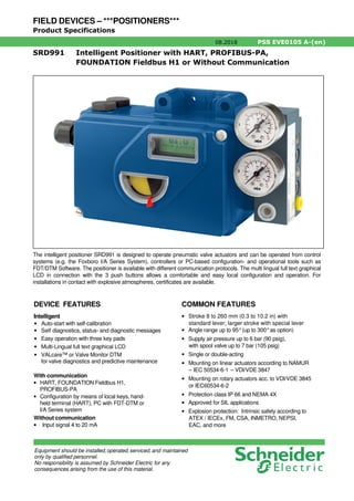
  • 1. FIELD DEVICES – ***POSITIONERS*** Product Specifications 08.2018 PSS EVE0105 A-(en) SRD991 Intelligent Positioner with HART, PROFIBUS-PA, FOUNDATION Fieldbus H1 or Without Communication DEVICE FEATURES Intelligent • Auto-start with self-calibration • Self diagnostics, status- and diagnostic messages • Easy operation with three key pads • Multi-Lingual full text graphical LCD • VALcare™ or Valve Monitor DTM for valve diagnostics and predictive maintenance With communication • HART, FOUNDATION Fieldbus H1, PROFIBUS-PA • Configuration by means of local keys, hand- held terminal (HART), PC with FDT-DTM or I/A Series system Without communication • Input signal 4 to 20 mA COMMON FEATURES • Stroke 8 to 260 mm (0.3 to 10.2 in) with standard lever; larger stroke with special lever • Angle range up to 95°(up to 300°as option) • Supply air pressure up to 6 bar (90 psig), with spool valve up to 7 bar (105 psig) • Single or double-acting • Mounting on linear actuators according to NAMUR – IEC 50534-6-1 – VDI/VDE 3847 • Mounting on rotary actuators acc. to VDI/VDE 3845 or IEC60534-6-2 • Protection class IP 66 and NEMA 4X • Approved for SIL applications • Explosion protection: Intrinsic safety according to ATEX / IECEx, FM, CSA, INMETRO, NEPSI, EAC, and more The intelligent positioner SRD991 is designed to operate pneumatic valve actuators and can be operated from control systems (e.g. the Foxboro I/A Series System), controllers or PC-based configuration- and operational tools such as FDT/DTM Software. The positioner is available with different communication protocols. The multi lingual full text graphical LCD in connection with the 3 push buttons allows a comfortable and easy local configuration and operation. For installations in contact with explosive atmospheres, certificates are available. Equipment should be installed,operated,serviced,and maintained only by qualified personnel. No responsibility is assumed by Schneider Electric for any consequences arising from the use of this material.
  • 2. PSS EVE0105 A-(en) Page 2 Contents Page • Special Versions of SRD991................................4 Common technical data for all basic devices ...5 • Operation, Diagnostics, Service plug...................6 • Electrical classification.........................................9 Extended technical data for basic devices: • With communication HART................................10 • With communication PROFIBUS or FOUNDATION Fieldbus.................................11 • Basic device without communication (4-20 mA) 12 Additional equipment for basic devices ..........13 (built into the basic device) • Pressure sensors for premium diagnostics........13 One Option board with additional inputs / outputs: • 2 Binary inputs or ..............................................14 • 2 Binary outputs or............................................15 • 2 Binary in/outputs or........................................16 • Position feedback and Alarm or........................17 • Entry for remote Potentiometer..........................18 Additional built-in • Limit signal switch ..............................................19 Contents Page FUNCTIONAL DESIGNATIONS......................... 21 MODEL CODES SRD991 ................................... 22 ACCESSORIES for mounting to the positioner: • Booster • Manifolds • Gauge manifolds........... 24 ATTACHMENT to actuators................................ 27 DIMENSIONS...................................................... 31 Option boards "Additional i/o" Service plug Cable glands Electronics version: Communication HART, PROFIBUS PA, FOUNDATION Fieldbus or "Without Communication" Limit signal switch Pressure sensors Manifold Booster G 1/4 CONTENTS SRD991
  • 3. PSS EVE0105 A-(en) Page 3 OVERVIEW The SRD991 consists of a basic device with a digital controller that supports different communication protocols (or also simply 4-20 mA input). Into this basic device, additional equipment can be built such as plug-in cards for electrical input/output signals, position feedback and pressure sensors. The pneumatic part is available in different versions (single / double acting or spool valve). For very large actuators, boosters with increased air capacity can be flanged on. Also, different manifolds for connection of gauges can be flanged on. For the pneumatic screw connections, we offer different threads in the housing and adapters. For use in hazardous areas, there are approvals according to ATEX / IECEx, FM, CSA, EAC, NEPSI, etc. The device can be configured locally by means of push buttons and LCD / LED, or with PC + EDC82 Modem connected to the service plug of the SRD991. By means of communication, the device can be configured remotely via FDT/DTM. A large variety of attachment kits for all common valves and actuators are available. The list “AttachmentKits.pdf” is updated continuously and can be found on the Internet. For high temperature or high vibration application, we recommend to mount the SRD991 remotely and not directly on the valve. For this, use the potentiometer unit (like the SRI990 - TXQxxxxx - H). Please consult TI EVE0105 R for specifications. To ensure the high performance of the positioner, we offer Advanced Diagnostics and Premium Diagnostics utilities: Premium Diagnostics Advanced Diagnostics Autostart Yes Yes Custom Characterization Yes Yes Auto diagnostic Yes Yes Alarm Management Yes Yes Alarm Output for Switching (with Option board) Yes Yes Status List acc. NE107 Yes Yes Position History Yes Yes Response History Yes Yes On Line Friction Yes Stepping Signature Yes Ramping Signature Yes Sensitivity Signature Yes Valve Signature Yes PST (Partial Stroke Test) Yes PST Predictive Maintenance Yes Additional equipment, built into the basic device: Option Board “2 Binary Inputs” or B 2 external switches (supplied by SRD) release a control function in the SRD, e.g. "close valve" (configurable) Option Board “2 Binary Inputs/Outputs” or E 2 channels, each configurable as an input or output (to be supplied externally) Option Board “Position Feedback” F 1 output 4-20 mA (to be supplied externally) gives stroke / angle of rotation; 1 alarm output becomes active with a configurable event Limit switch T,U, R,V Supplies NAMUR signals when exceeding or falling below of two limit values. Inductive sensors, independent of the controller, in normal or safety version or three-wire, or micro switches D Entry for remote potentiometer of external potentiometer unit Pressure sensors 2 sensors measure the pressure of supply air and output y1 for Premium Diagnostics; the values are passed on via communication LCD Full text graphic LCD in 3 languages Accessories like Manifolds and Boosters see page 24. SRD991 OVERVIEW
  • 4. PSS EVE0105 A-(en) Page 4 3 0 0 ° Special Versions of SRD991: SRD991 Stainless Steel Housing To be order with model code SRD991-xxxxxxxx-Zxxx Please consult TI EVE0105 INOX for specifications. For dimensional drawings see page 33. SRD991 for Top Mounting onto small actuators This version is designed for direct mounting on top of small actuators without yoke - solution for actuators up to 50 mm stroke. Instead of the rotary potentiometer, a linear pot is used that feeds back the actual position of the actuator. The Model Code of this basic device is SRD991- ............. -W The adapter part is dependent on the manufacturer and type of actuator and can be ordered under the code EBZG-TMxx. Please consult TI EVE0105 TM for specifications. SRD991 designated for PST (Partial Stroke Test for Emergency Shut Down) Final control elements in Emergency Shutdown (ESD) applications such as ON-OFF-, Blow Down and Venting valves remain in one position over a long time without any mechanical movement. These valves can show a tendency to get stuck and as a result might not operate upon demand. This can have a severe impact on the functionality of a Safety System and could result in an adverse condition to the operating personnel, plant equipment and the environment. The Partial Stroke Test (PST) offers operators a tool to identify the troubleshooting function of ESD valves. The test can be easily executed via the FDT-DTM based configuration diagnostic tool VALcare™/Valve Monitor. Please consult TI EVE0105 PST. SRD991 for actuator with rotation up to 300° This special version of the SRD991 is designed to be mounted by means of standard attachment kit (like the EBZG-R) onto rotary actuator with rotation up to 300° . This special version is made of a standard SRD991 with special gears. To be ordered under Options -J. Please consult TI EVE0105 LR. SPECIAL VERSIONS OF SRD991
  • 5. PSS EVE0105 A-(en) Page 5 Travel range Stroke range . . . . . . . . . . . . 8 to 260 mm (0.3 to 10.2 in) with standard feedback levers; special levers on request Rotation angle range . . . . . . up to 95°without mechanical stop; up to 300°with Option –J. Supply Supply air pressure . . . . . . . 1.4 to 6 bar (20 to 90 psig) with spool valve 1) . . . . . . 1.4 to 7 bar (20 to 105 psig) Output to actuator . . . . . . . . 0 to ~100 % of supply air pressure (up to 5.5 bar at 6 bar supply air pressure) with spool valve heavy duty2) : 4 to 10 bar Air supply. . . . . . . . . . . . . . . according to ISO 8573-1 - Solid particle size and density class 2 - Oil rate. . . . . . . . . . . . . . . class 3 - Pressure dew point 10 K under ambient temperature The use of filter regulator for air supply of positioner is strongly recommended. It reduces the air pressure to actuator’s maximum pressure and keeps it constant. For supply with Natural Gas instead of compressed air please consult TI EVE0105 G. Air output ln/h (scfh) at max. deviation, single and double acting: Supply air pressure bar (psig) 1.4 (20) 3 (45) 6 (90) Standard Amplifier 2 700 (95) 5 000 (177) 7 500 (265) with Spool Valve 1) 6 000 (211) 12 000 (423) 18 000 (636) “Heavy duty” spool valve 2) is able to deliver up to 55,000 ln/h at 10 bar. Please consult TI EVE0105 INOX. Note: The use of boosters in connection with Spool valve is not recommended. Air consumption (steady state) ln/h (scfh) Supply air pressure bar (psig) 1.4 (20) 3 (45) 6 (90) single acting 80 (2.8) 130 (4.6) 220 (7.8) double acting 130 (4.6) 230 (8.1) 430 (15.2) Spool Valve 100 (3.5) 240 (8.5) 500 (17.7) Response characteristic 3) 4) Sensitivity . . . . . . . . . . . . . . < 0.1 % of travel span Non-linearity (terminal based adjustment) . . . . . . . . < 0.4 % of travel span Hysteresis . . . . . . . . . . . . . . < 0.3 % of travel span Supply air dependence. . . . . < 0.1 % / 1 bar (15 psi) Temperature effect. . . . . . . . < 0.3 % / 10 K Mechanical vibration 10 to 60 Hz up to 0.14 mm, 60 to 500 Hz up to 2 g . . . . . < 0.25 % of travel span Volume Booster Series (to order as accessory) For large actuators or to reduce action time, a volume booster may be necessary. VBS200 / VBS201 / VBS202 Volume booster with Cv 2 and pneumatic connection 1/2”, for direct side mounting to positioner, remote mounting, or mounting acc. to VDI/VDE 3845 For more information please consult PSS EVE0602. VBS300 / VBS310 Volume boosters with Cv7 and pneumatic connection 1’’, for remote mounting VBS300 in Aluminum, VBS310 in Stainless Steel 316 For more information please consult PSS EVE0603. 1) Spool valve is the type of amplifier used in device SRD991-Cxxxxx-S 2) Spool valve heavy duty is the amplifier used in stainless steel version SRD991 - Cxx... - SZK 3) Data measured according to VDI/VDE 2177 4) With stroke 30 mm and lever length 90mm FUNCTIONAL SPECIFICATIONS (common data for all versions) SRD991 FUNCTIONAL SPECIFICATIONS
  • 6. PSS EVE0105 A-(en) Page 6 Features Automatic start-up . . . . . . . (Autostart functionality) Automatic determination of the mechanical end positions of the valve (initial value and final value), IP motor parameters, direction of action of the spring and control parameters. The control parameters are optimized dynamically during this routine. This procedure makes a perfect adjustment and optimiza- tion to the actuator possible without additional manual settings! Several autostart modes are available (details see on next page). Options • Built-in independent inductive limit switches • Pressure sensors for monitoring of air supply and out- put pressure I (y1) • Additional inputs / outputs: • Position feedback 4-20 mA + binary alarm output, to be supplied external • 2 binary outputs (position alarms) • 2 binary inputs, to be supplied external • 2 contact inputs, internal supplied • 2 binary in-/outputs, to be supplied external Operation and Configuration The local LCD enables a fast and easy configuration as well as diagnostic. Local . . . . . . . . . . . . . . . . . . with local key pads Display. . . . . . . . . . . . . . . . . Multi-lingual Graphic LCD, some versions with 5 LEDs The positioner in the version with LCD contains three different menu languages. Standard menu languages: - English - German Freely selectable third language: - French - Portuguese - Spanish - Italian - Swedish - and more (further menu languages see Model Code page 23). The third menu language has to be selected and specified with the order, otherwise standard: French. The third, freely selectable menu language can be modified to another language by means of the VALcare™ DTM. 2) The additional languages can be downloaded from our homepage. Diagnostics – in the field: • Status and Diagnostic messages via LCD – via VALcare™ or Valve Monitor DTM 4) : • Service Management for planning and scheduling of service intervals • Histograms for displaying the position- and response- history over time • Partial Stroke Test for the functional inspection of safety related actuators • Hours in operation, cycle counter and travel sum of the actuator are determined • Surveillance of loop current • Shows condition of device: -Potentiometer -IP Motor -Exceeding range of actuator (possible indication for wear of plug or seat) -Remaining control deviation (possible indication for jam- med actuator, blocked valve stem or plug, insufficient air capacity / supply air pressure / positioning pressure) • If equipped with pressure sensors (optional, see page 3): • Monitoring of the stem friction • Histograms for displaying the friction-history over time • Surveillance of air supply and output pressure, each with display of physical value • Additional diagnostically possibilities in control operation by means of external sensors (optional). See also the VALcare™ Documentation. Service plug All basic devices are equipped with a service plug A at the front side. There via RS232 interface a PC with VALcare (DTM) can be connected via modem EDC82 (galv. separa- ted, not Ex). Information about EDC82 modem see TI EVE0102 Y. 2) With the versions “Intelligent without communication” this is only possible with modem EDC82 3) By means of “Additional inputs / outputs” 4) For the SRD991 without communication the use of the service plug is necessary to have access at the diagnostic with DTM FUNCTIONAL SPECIFICATIONS (common data for all versions) A FUNCTIONAL SPECIFICATIONS SRD991
  • 7. PSS EVE0105 A-(en) Page 7 Manual local and remote settings: Actuator mode . . . . . . . . . . . linear or rotary actuator Linear valve . . . . . . . . . . . left or right mounted Rotary actuator. . . . . . . . . opening clockwise or counter-clockwise Characteristic of set point . . . linear, equal percentage, inverse-equal percentage or custom (22 points) Valve function . . . . . . . . . . . opens or closes with increasing set point Split range . . . . . . . . . . . . . free upper and lower values Travel limits . . . . . . . . . . . . . free upper and lower values Cutoffs. . . . . . . . . . . . . . . . . free upper and lower values Stroke range . . . . . . . . . . . . configurable Temperature unit . . . . . . . . . configurable (° C or ° F) Autostart . . . . . . . . . . . . . . . - Endpoints - Standard Autostart - Enhanced Autostart - Smooth response - Fast response Control parameters . . . . . . . Determined during Autostart. Working range . . . . . . . . . . . freely adjustable (for indication on LCD) Manual adjustment of. . . . . . P-gain, I-time, D-time, T63-time and dead band Manual operation . . . . . . . . . Manual input of set point to drive the valve in steps of 12.5%, 1% or 0.1% Pneumatic test. . . . . . . . . . . Function to test the pneu- matic output Workshop . . . . . . . . . . . . . . input and angle calibration LCD language . . . . . . . . . . . dependent on version LCD orientation . . . . . . . . . . dependent on version PROFIBUS-PA . . . . . . . . . . Bus address FOUNDATION Fieldbus . . . Simulation Switch from Link Master to Basic Field Device Software supported configurations: - By means of Hand Held Terminal (HART) - PC by means of VALcare Software - I/A Series System, Foxboro Evo and other DCSs Failure handling In case of Single Acting, Safety position at - Air supply failure . . . . . . . . pressure y1 = zero - Electric power failure . . . . . pressure y1 = zero - Failure of electronics . . . . . pressure y1 = zero In case of Double Acting or spool valve amplifier, safety position at - Air supply failure . . . . . . . . pressure y1 = zero / y2 = zero - Electric power failure . . . . . pressure y1 = zero / y2 = full air supply pressure - Failure of electronics . . . . . pressure y1 = zero / y2 = full air supply pressure For all types of amplifiers (with FF H1 or Profibus PA) - Failure of communication is recognized by configurable watch dog with response delay of 0.1 s to 24 h Behavior . . . . . . . . . . . . . . . configurable as - pressure y1 = zero or - stop at last value or - a configured value Diagnostic report . . . . . . . . . via communication and local LCD - Historical status . . . . . . . . . is set if alarm was activated at any time (also just short alarms) Reset. . . . . . . . . . . . . . . . . by acknowledging Spool Valve Amplifier for single and double acting application Spool valve amplifier as option for the SRD991 can be used with double acting actuator and also with single acting actuator. In case of single acting application, one of the pneumatic output must be closed: - If y1 is used, y2 is closed and failure handling for Electric power failure and Failure of electronics becomes y1=zero. - If y2 is used, y1 is closed and failure handling for Electric power failure and Failure of electronics becomes y2=full air supply. SRD991 SETTINGS
  • 8. PSS EVE0105 A-(en) Page 8 Mounting Attachment to stroke actuators - direct, FlowPak/FlowTop . . with attachment kit EBZG –E - for casting yoke acc. to IEC 534-6 (NAMUR) with attachment kit EBZG –H or –H1 - for pillar yoke acc. to IEC 534-6 (NAMUR) with attachment kit EBZG –K or –K1 Stroke range with feedback lever: - standard (EBZG-A ) 8 to 70 mm / 0.31 to 2.76 in - extended (EBZG-B ) 60 to 120 mm / 2.36 to 4.72 in - extended (EBZG-A1) 110 to 260 mm / 4.33 to 10.24 in Larger stroke ranges can be realized with special levers. Attachment to rotary actuators acc. to VDI/VDE 3845............with attachment kit EBZG -R - Further attachment kits see Model Codes page 26 - Mounting orientation see attachment dimensions starting from page 27 Materials Housing and covers . . . . . . . Aluminum (Alloy No. 230) finished with DD-varnish All moving parts of feedback system . . . . . . . . . 1.4306 / 1.4571 / 1.4104 Attachment kits . . . . . . . . . . V4A or Aluminum, finished with DD varnish (depending upon version) . . (Alloy No. 230) Mounting bracket . . . . . . . . . Aluminum (Alloy No. 230) Pneumatic diaphragms . . . . PVMQ (Silicone elastomer suitable for use in the paint industry) Weight Single acting . . . . . . . . . . . . approx. 1.7 kg (3.7 lbs) Double acting. . . . . . . . . . . . approx. 2.0 kg (4.4 lbs) Pneumatic connection NAMUR mounting . . . . . . . . G 1/4 for pipe diameter 6 to 12 mm (0.24 to 0.47 in) for air supply and outputs y1, y2 to the actuator; 1/4-18NPT with additional connection manifold Direct mounting . . . . . . . . . . Instead of the output y1, an air connection on the back with O-ring will be used (closed at NAMUR mounting). Electrical Connection Line entry. . . . . . . . . . . . . . . 1 or 2 cable glands 1/2-14 NPT or M20 x1.5 (others with Adapter AD-...) Cable diameter . . . . . . . . . . 6 to 12 mm (0.24 to 0.47 in) Screw terminals . . . . . . . . . . 2 terminals for input, 4 terminals for additional inputs / outputs; Tightening torque . . . . . . . min. 0.5 Nm, max. 0.6 Nm Wire cross section . . . . . . solid wire 0.5 to 6 mm2 stranded wire 0.5 to 4 mm2 crimped wire . . . . . . . . . 0.5 to 2.5 mm 2 (AWG 21-14) Test sockets. . . . . . . . . . . integrated in terminals, for options and communicator connection Ambient conditions Operating conditions . . . . . . acc. to IEC 654-1 The device can be operated at a class Dx location Ambient temperature Operation 1) . . . . . . . . . . . –40 to 80 ° C (–40 to 176 ° F) Transport and storage . . . –40 to 80 ° C (–40 to 176 ° F) If the device is exposed to sunlight and the temperature may rise above 80 ° C, we recommend a sun shade. Storage conditions acc. to IEC 60721-3-1: . . . 1K5; 1B1; 1C2; 1S3; 1M2 Indicators LCD (visible) 2) . . . . . . . . . –25 to 70 ° C (–13 to 176 ° F) LEDs (if present). . . . . . . . –40 to 80 ° C (–40 to 176 ° F) Relative humidity . . . . . . . . . up to 100 % Protection class 3) acc. to IEC 60529. . . . . . . IP 66 acc. to NEMA . . . . . . . . . . Type 4X Electromagnetic compatibility EMC Operating conditions . . . . . . industrial environment Immunity according to EN 61326 . . . . . . . . . . . . . . fulfilled IEC 61326 . . . . . . . . . . . . . . fulfilled EN 61000-6-2 . . . . . . . . . . . fulfilled Emission according to EN 61326 Class A and Class B. . . . . fulfilled EN 61000-6-4 . . . . . . . . . . . fulfilled EN 55011 Group 1, Class A and Class B. . . . . fulfilled NAMUR recommendation EMV NE21 . . . . . . . . . . . . fulfilled SAFETY REQUIREMENTS CE label Electromagnetic Compatibility 4) . . . . . . . . . . . 2004/108/EC Low-voltage regulation . . . . . not applicable Safety According to EN 61010-1 (or IEC 61010-1) . . . . . . . . . Safety class III Overvoltage Category I Internal fuses . . . . . . . . . . . . only with PROFIBUS or FOUNDATION Fieldbus, but not replaceable External fuses . . . . . . . . . . . Limitation of power supplies for fire protection must be observed acc. to EN 61010-1, appendix F (or IEC 61010-1). 1) Details see Certificates of Conformity. With Limit Switches Code T only –20 ° C. With Limit Switches Code R only –25 to 70 ° C 2) Below –20 ° C the LCD reacts only slowly; above 70 ° C the background becomes dark 3) Under service as directed 4) With PROFIBUS or FOUNDATION Fieldbus only, if shield of wiring is grounded on both sides 5) Pneumatic connection 1/4-18 NPT made with a separate manifold delivered together with the device FUNCTIONAL SPECIFICATIONS (common data for all version) FUNCTIONAL SPECIFICATIONS SRD991
  • 9. PSS EVE0105 A-(en) Page 9 Electrical classification 1) 2) See Certificates of Conformity EX EVE0105 A Type of protection “Intrinsically Safe” ATEX / IECEx Marking ...................................Ex ia IIC T4 Gb, Ex ia IIC T6 Gb Temperature classes Version with HART communication and "without communication": T4 with explosion protection code EA4 Version with communications HART, FOUNDATION Fieldbus and PROFIBUS-PA: T4 / T6 with explosion protection code EAA Certificate of Conformity ....... IECEx EPS 16.0034 EPS 16 ATEX 1 083 For use in hazardous areas in circuits certified as intrinsic- ally safe with the following maximum values: Profibus / Fieldbus HART Ui 24 V DC Ui 30 V DC Ii 380 mA Ii 130 mA Pi 5.32 W Pi 0.9 W Ci 1.3 nF Ci 1.3 nF Li 5 µH Li 5 µH Ci: effective inner capacity Li: effective inner inductivity The supply connections have an inner capacity of max. 5.3 nF opposite the ground. Ambient temperature ranges: Temperature class T4: . . . . –40 ° C to 80 ° C Temperature class T6: . . . . –40 ° C to 55 ° C Explosion protection Zone 2 / 22 Installation of the SRD991 in potentially explosive atmo- spheres for Zone 2 / 22 (explosion protection II 3 G/D Ex ic Gc/Dc) The Intelligent Positioner SRD991 in protection level intrinsic safety "ic" (II 3 G/D Ex ic Gc/Dc) can also be operated in potentially hazardous areas of Zone 2 / 22. Explosion protection Zone 20 EX II 1D Ex ia IIIC T 100° C Da. . . . . –40 ° C < Ta < 100 ° C Electrical Data Supply circuit in type of protection Intrinsic Safety Ex ia. The positioner type SRD991 fulfils the requirements of explosion protection for the Equipment Group II and Category 1D in type of protection Intrinsic safety for dust with a maximum surface temperature of 100 ° C. FM Type of protection IS / I, II, III / 1 / ABCDFG / T4 Ta = 80° C, T6 Ta = 55 ° C Entity; Type 4X; DOKZ 534 396 049 NI / I / 2 / ABCD; S / II, III / 2 / FG / T4 Ta = 80 ° C, T6 Ta = 55 ° C; Type 4X CSA PROCESS CONTROL EQUIPMENT-Intrinsically Safe, Entity - For Hazardous Locations Class I, Groups, A, B, C and D; Class II, Groups E, F and G; Class III: Ex ia IIC T4/T6 IP65: • SRD 991 HART/4-20mA/FOXCOM/Profibus/Fieldbus- abcdefgh-j Positioner: 12-36 V dc, 4-20 mA or < 48 V dc, Intrinsically safe when installed as per submittor's Dwg DOKZ 534 396 067 or DOKZ 534 396 076; Temp. Code T4 at Max Amb. 80C or T6 at Max Amb. 55C. Note: Model No is followed by suffix abcdefgh-j denoting minor mechanical differences and options not affecting safety. With Electrical Classification ATEX + Zone 20 Dust, Codes ED4 and EDA, the Travel indicator is not visible. 1) With appropriate order only 2) National requirements must be observed 3) Standard has been replaced by a new standard or revision. The products are according to these new standards or revisions, because the modified requirements are not relevant. SRD991 ELECTRICAL CLASSIFICATION
  • 10. PSS EVE0105 A-(en) Page 10 SRD991 with HART communication SRD991-xHxxxx Signal Input . . . . . . . . . . . . . Two wire system Reverse polarity protection. . standard feature Signal range . . . . . . . . . . . . 4-20 mA Operating range. . . . . . . . . . 3.6 to 21.5 mA Input voltage . . . . . . . . . . . . DC 12 to 36 V 1) (unloaded) Load . . . . . . . . . . . . . . . . . . 420 Ohms, 8.4 V at 20 mA Communication signal . . . . . HART, 1200 Baud, FSK (Frequency Shift Key) modulated on 4-20 mA 0.5 Vpp at 1 kOhm load Input impedance Zi. . . . . . . . Z = 320 Ohms for ac voltage 0.5 to 10 kHz with < 3 dB non-linearity Cable capacity and inductance see HART standard specifications (e.g. C < 100 nF). Impedance of other devices at the input (parallel or serial) must be within HART spec. Applications without communication require not to exceed input capacitance parallel to the input not higher than 100 µF. Start-up time . . . . . . . . . . . . approx. 3 sec Interruption time without power down: with LCD . . . . . . . . . . . . . typ. 80 ms 2) 1) On request we can specify higher voltage limits 2) Worst case conditions 4-20 mA, with position feedback option, i/p-output with max. current Configuration The SRD991 can be configured via HART by any host system whatever is a PC with a HART Modem, Hand Held Terminal or a DCS. LOCAL (by means of local key pad and LCD display) See page 6 DTM (Device Type Manager) We are a leading company in term of FDT-DTM technology http://www.fdtgroup.org/product-catalog/certified-dtms?com pany=Foxboro+Eckardt+GmbH&field_device_type_value_ many_to_one=All&field_protocol_value_many_to_one=All Therefore we provide a DTM fully certified for it’s inter- operability and with the state-of-the-art presentation and diagnostics features. The DTM can be downloaded from our homepage. DD (Device Description) and EDD (Enhanced Device Description) In case the host system is not supporting the FDT-DTM technology, you can download the DD and/or EDD from our homepage. COMMUNICATION HART SRD991
  • 11. PSS EVE0105 A-(en) Page 11 PROFIBUS-PA Data transfer . . . . . . . . . . . . according to PROFIBUS- PA profile class B based on EN 50170 and DIN 19245 part 4 GSD file . . . . . . . . . . . . . . . .the actual file can be down- loaded from our homepage Configuration Local / Display . . . . . . . . . . . see page 6 Software . . . . . . . . . . . . . . . VALcare™ -DTM Hardware. . . . . . . . . . . . . . . PC- or PCMCIA- interfaces from Softing I/A Series System . . . . . . . . FBM 223 in combination with CP60 Other control systems . . . . . All Profibus-PA- compatible, e.g. Siemens SIMATIC PDM (Process Device Manager) FOUNDATION Fieldbus H1 Data transfer . . . . . . . . . . . . FF Specification Rev. 1.4, Link-Master (LAS) Two revisions of Firmware can be selected for the FOUNDATION Fieldbus devices in the model code of the positioner. The selection of the Firmware revision is depending of the DCS compatibility, the DD Files already installed in the DCS and the installed base on your site. Double check interoperability of following characteristics with your DCS before ordering! When selected Firmware FF16 in the model code : Certified according to . . . . . . ITK 4.6 Function Blocks . . . . . . . . PID, AO, 2xDI, 1xDO Transducer, Resource When selected Firmware FF18 in the model code : Certified according to . . . . . . ITK 6.0.1 Function Blocks . . . . . . . . PID, AO, 4xDI, 1xDO, IS, OS, AI, MAI, Transducer, Resource Additional functionality . . . Flat Addressing DD files . . . . . . . . . . . . . . . . the actual file can be down- loaded from our homepage Configuration Local / Display . . . . . . . . . . . see page 6 Software . . . . . . . . . . . . . . . VALcare™ -DTM or National Instruments NI-FBUS configurator Hardware. . . . . . . . . . . . . . . FBUS-interfaces from National Instruments (AT-FBUS and PCMCIA- FBUS I/A Series System . . . . . . . . FBM220 or FBM221 in combination with CP60 Other control systems . . . . . All FOUNDATION Fieldbus H1- compatible, e.g. SMAR, Fisher Rosemount Delta-V, Honeywell, Yokogawa, ABB For both fieldbus devices Input signal . . . . . . . . . . . . . digital Supply voltage . . . . . . . . . . . DC 9 to 32 V 1) max. Supply voltage. . . . . . . DC 36 V Operating current. . . . . . . . . 10.5 mA ±0.5 mA(base current) Current amplitude . . . . . . . . ± 8 mA Fault current. . . . . . . . . . . . . Base current + 0 mA (base current + 4 mA by means of independent FDE-safety circuit) according to IEC 1158-2 Operating values . . . . . . . . . according to IEC 1158-2 Start-up time (init phase) . . . approx. 2 sec Bus connection . . . . . . . . . . Fieldbus interface based on IEC 1158-2 according to FISCO-Model Power supply. . . . . . . . . . . . Power supply is achieved dependant on the application by means of fieldbus power supply units or segment coupler Electrical classification thereto see page 9 SRD991 without communication SRD991-xDxxxx Signal Input . . . . . . . . . . . . . Two wire system Reverse polarity protection. . Standard feature Signal range . . . . . . . . . . . . 4-20 mA Operating range. . . . . . . . . . 3.6 to 21.5 mA Input voltage . . . . . . . . . . . . DC 8.5 to 36 V 2) (unloaded) Load . . . . . . . . . . . . . . . . . . 300 Ohms, 6 V at 20 mA With applications without communication the capacity parallel to input may not be higher than 100 µF. Start-up time . . . . . . . . . . . . approx. 3 sec Interruption time without power down: with LCD . . . . . . . . . . . . . typ. 80 ms 3) Configuration Local / Display . . . . . . . . . . . see page 6 Software . . . . . . . . . . . . . . . VALcare™ (DTM) Hardware. . . . . . . . . . . . . . . per modem EDC82 Electrical classification thereto see Page 9 1) Data of ”Intrinsically Safe” version 2) On request we can specify higher voltage limits 3) Worst case conditions 4-20 mA, with position feedback option, i/p-output with max. current SRD991 with communication PROFIBUS-PA and FOUNDATION Fieldbus H1 SRD991-xPxxxx or SRD991-xQxxxx SRD991 COMMUNICATION PB & FF
  • 12. PSS EVE0105 A-(en) Page 12 C o d e T - U - R - ( V ) C o d e D 4 0 5 0 5 0 OVERVIEW ADDITIONAL EQUIPMENT (built into any basic device) Built-in Pressure sensors for Premium Diagnostic, Code Option –B For supply air and output y1 to actuator Measuring range . . . . . . . . . 0 to 8 bar (0 to 120 psig) Accuracy . . . . . . . . . . . . . . . 2 % Temperature influence . . . . . 0.5 % / 10 K (–40 to 80 ° C) Pressure sensors 50 Additional Inputs / Outputs: One module “Additional inputs / outputs” 8 can be plugged onto main electronics 40 : • 2 Binary inputs or • 2 Binary in/outputs or • Position feedback and Alarm Details see following pages. Built-in Limit Switch Details see page 19 Parts Kits for additional installation of auxiliary functions Model codes, Additional inputs / outputs Supply Parts Kit Code B: 2 Binary inputs (Contact inputs) internal EW 411 407 325 Code E: 2 Binary in/outputs external EW 411 407 956 Code F: Position feedback 4-20 mA and Alarm (ATEX) external EW 426 434 228 Model codes, Limit signal switches Code T: Limit signal switch, normal version external EW 426 164 012 Code U: Limit signal switch, security version external EW 426 164 021 Code R: Limit signal switch, 3-wire external EW 426 164 057 Code V: Limit signal switch, micro switches external EW 426 164 066 Code D: Entry for remote potentiometer internal EW 426 164 093 8 4 0 OVERVIEW ADDITIONAL EQUIPMENT SRD991
  • 13. PSS EVE0105 A-(en) Page 13 Additional Inputs / Outputs: Two Binary (Contact) inputs – Code B Two independent binary inputs, supplied with the basic device, for connection of external switches. A connected switch is loaded with 3.5 V, 150 µA. This option 'Binary inputs' can also be used to activate PST (Partial Stroke Test). The binary inputs can be used for diagnostics or are also configurable for the control functions: Switch 1 Switch 2 Actuator control function close close normal operation open close go to stop at 0 % close open go to stop at 100 % open open hold last position Terminals for EB1 . . . . . . . . K2/1 + : 13 K2/2 – : 14 EB2. . . . . . . . K3/1 + : 15 K3/2 – : 16 For further information about the contact inputs please consult TI EVE0105 B. Electrical Classification ATEX / IECEx Types of protection and temperature classes of basic device, see page 9. Additions for this option in EC-Certificate of Conformity IECEx EPS 16.0034 and EPS 16 ATEX 1 083: To this electric circuit only passive electric circuits galva- nically separated from earth may be attached. The electric circuit has the following maximum values: Uo= 7.88 V, Io= 11.4 mA, Po= 23 mW Characteristic is linear. For the maximum values of outer inductances and capa- cities Lo and Co refer to the following table (Li and Ci included): IIC IIB Lo [mH] Co [µF] Lo [mH] Co [µF] 100 0.72 100 3.9 10 1.1 10 5.5 1 1.6 1 8.7 0.1 2.7 0.1 15 0.01 4.7 0.01 27 The electric circuits of "2 binary inputs" are galvanically connected with all other circuits and isolated from earth. One module “Additional inputs / outputs” 8 can be plugged onto main electronics 40: • 2 Binary inputs or • 2 Binary in/outputs or • Position feedback and Alarm DTM Configuration window ADDITIONAL EQUIPMENT built into any basic device 8 4 0 SRD991 ADDITIONAL EQUIPMENT
  • 14. PSS EVE0105 A-(en) Page 14 Additional Inputs / Outputs: Two binary in/outputs – Code E This option board is recommended for PST applications. Output: 2 galvanically separated signals Limit signals / alarms freely configurable via local keys or via communication. Two-wire system, according to DIN 19234, for external supply. Supply voltage . . . . . . . . . . . DC 8 to 36 V 1) 2) Configured as NAMUR signal: Logic: Limit value not exceeded. . . < 1 mA Limit value exceeded. . . . . . typ. 6 mA Device fault. . . . . . . . . . . . < 50 µA Configured as On/Off signal: Limit value not exceeded. . .< 50 µA Limit value exceeded. . . . . .> 20 mA/20 V / > 40 mA/10 V (power derated) Reference: AB1 for upper, AB2 for lower limit value Terminals for AB1 . . . . . . . . K2/1 + : 81 K2/2 – : 82 AB2. . . . . . . . . K3/1 + : 83 K3/2 – : 84 Input: The kind of Signals Input can be configured as On/Off or as NAMUR signal in accordance to DIN 19234. Configured as NAMUR signal: Unloaded supply voltage . . . > 8 V Input Logic 0. . . . . . . . . . . . . . . . . > 0.35 mA, < 1 mA Logic 1. . . . . . . . . . . . . . . . . > 2.2 mA, < 6 mA Input current Limited to. . . . . approx. 6 mA Configured as On/Off signal: Input: Logic 0. . . . . . . . . . . . . . . . . < 4 mA Logic 1. . . . . . . . . . . . . . . . . > 6 mA Signal Voltage Range . . . . . 8 to 36 V 1) Electrical Classification ATEX / IECEx: Types of protection and temperature classes as basic device, see page 9. Additions for this option in EC-Certificate of Conformity IECEx EPS 16.0034 and EPS 16 ATEX 1 083: For use in hazardous areas in circuits certified as intrinsic- ally safe with the maximum values as described in the Certificate of Conformity in chapter “Option UNI-IO”. The circuits Channel 1 and Channel 2 are electrically safe separated from each other, from all other external circuits and from earth. 1) Other values in hazardous areas 2) On request we can specify higher voltage limits One module “Additional inputs / outputs” 8 can be plugged onto main electronics 40: • 2 Binary inputs or • 2 Binary in/outputs or • Position feedback and Alarm DTM Configuration window 8 4 0 ADDITIONAL EQUIPMENT SRD991
  • 15. PSS EVE0105 A-(en) Page 15 Additional Inputs / Outputs: – Code F Position feedback 4-20 mA and Alarm with electrical classification ATEX / IECEx Stroke / angle derivated from positioner feedback 1 output analog, galvanically separated, two-wire system according to DIN 19234, for external supply Supply voltage . . . . . . . . . . DC 8 to 36 V 1) 2) Signal range . . . . . . . . . . . . 3.8 to 20.5 mA 0 % and 100 % configurable Device fault. . . . . . . . . . . . . .< 50 µA Terminals for AI1 . . . . . . . . . K3/1 + : 83 K3/2 – : 84 Feedback signal can be reversed (20 --> 4 mA). 1 binary alarm output, galvanically separated, two-wire system, according to DIN 19234, for external supply Supply voltage . . . . . . . . . . . external, DC 8 to 36 V 1) 2) Logic . . . . . . . . . . . . . . . . . . no alarm . . .< 1 mA alarm . . . . . > 3 mA device fault < 50 µA configurable as switch output: Limit value not exceeded. . . < 50 µA Limit value exceeded. . . . . . > 20 mA/20 V / > 40 mA/10 V (power derated) Terminals for AB1. . . . . . . . . K2/1 + : 81 K2/2 – : 82 The binary output for Alarm will be activated in the following cases: - Remaining control deviation - Circuit to I/P module is disturbed - Circuit to potentiometer is disturbed - Calibration error: - no angle calibration - no current calibration - Autostart failed These pre-settings can be configured via communication with the Alarm Link function in the DTM. Electrical Classification ATEX / IECEx: Types of protection and temperature classes as basic device, see page 9. Additions for this option in EC-Certificate of Conformity IECEx EPS 16.0034 and EPS 16 ATEX 1 083: For use in hazardous areas in circuits certified as intrinsic- ally safe with the maximum values as described in the Certificate of Conformity in chapter “Option UNI-IO”. The circuits Channel 1 and Channel 2 are electrically safe separated from each other, from all other external circuits and from the earth. 1) Other values in hazardous areas 2) On request we can specify higher voltage limits One module “Additional inputs / outputs” 8 can be plugged onto main electronics 40: • 2 Binary inputs or • 2 Binary in/outputs or • Position feedback and Alarm DTM Configuration window 8 4 0 SRD991 ADDITIONAL EQUIPMENT
  • 16. PSS EVE0105 A-(en) Page 16 B C 1 2 2 8 A 1 9 C o d e T / U / R C o d e V C o d e D Entry for remote potentiometer (for remote mounting main unit) – Code D This remote application is used in applications where high temperatures or vibration are present and can result in negative influences to the control. It can also be used in places not easy to reach, to ensure an easier handling of the unit, or for cylinders with large strokes. The Positioner SRD991 (Remote unit) is mounted far away from the valve or cylinder in a safe environment. The Potentiometer unit is mounted on the valve or cylinder. This potentiometer unit can be made of a derivative version of the SRI990 positioner (only potentiometer in the housing) or of an external potentiometer like a linear potentiometer for application onto cylinders, for example. This option is to be used with a potentiometer unit 3 wires system with approx. 5 kOhm resistance. If the following requirements are observed, the set-up is insensitive to electrical disturbances caused by high electromagnetic fields, EMC and HF-radiation. Cable Length max. . . . . . . . . 10 m (32 ft) Cable Specification (not supplied by us): • 3-wire twisted pair, shielded • Shield needs to be connected on both ends to the internal ground • Shield endings need to be kept very short when connec- ting to the ground • A HF cable gland is not required For more information about remote mounting please consult TI EVE0105 R. Note: The functionality and certifications are only ensured with our 5 kOhm potentiometer. Electrical Classification ATEX / IECEx: Types of protection and temperature classes as basic device, see page 9. Additions for this option in EC-Certificate of Conformity IECEx EPS 16.0034 and EPS 16 ATEX 1 083: For use in hazardous areas in circuits certified as Intrinsically Safe with the following maximum values: Umax = 6.5 V I_supply = 25 mA I_wiper ≤ 1 mA P_total ≤ 40 mW ADDITIONAL EQUIPMENT SRD991
  • 17. PSS EVE0105 A-(en) Page 17 B C 1 2 2 8 A 1 9 C o d e T / U / R C o d e V C o d e D Built-in Limit Switches Stroke / angle derived from positioner feedback – Standard version (SJ2-N) .......Code T (only to –20° C) – Security version (SJ2-SN).....Code U – 3-wire (SI2-K08-AP7/ PNP)...Code R (no Ex, –25 to 70 ° C) – Micro switches (V4NS) ...........Code V (no Ex) – Entry for remote potentiometer Code D Materials Control vanes ........................... Aluminum Transmission shaft ................... 1.4571 SRD991 ADDITIONAL EQUIPMENT
  • 18. PSS EVE0105 A-(en) Page 18 Inductive Limit Switch (Code T, U) Output . . . . . . . . . . . . . . . . . 2 inductive proximity sensors acc. to DIN 19 234 or NAMUR for connection to switching amplifier 1) Current consumption Vane clear . . . . . . . . . . . . > 2.2 mA Vane interposed . . . . . . . . < 1 mA for control circuit with the following electrical values: Supply voltage . . . . . . . . . DC 8 V, Ri approx. 1 kOhm Supply voltage range. . . . . DC 5 to 25 V (with "no Ex") Residual ripple. . . . . . . . . . < 10 % p.p. Permissible line resistance . . . . . . . . . < 100 Ohms Response characteristic 2) 3) Switching differential . . . . . < 1 % Switching point repeatability < 0.2 % Terminals for GW1. . . . . . . . 41+, 42– GW2 . . . . . . . 51+, 52– Electrical Classification ATEX / IECEx of versions "T" and "U": Types of protection and temperature classes as basic device, see page 9. Additions for this option in EC-Certificate of Conformity IECEx EPS 16.0034 and EPS 16 ATEX 1 083: For use in hazardous areas in circuits certified as Intrinsic- ally Safe with the following maximum values: Ui= 16 V, Ii= 25 mA, Pi= 64 mW Internal capacitance and inductance: Ci= 30 nF, Li= 100 µH The electric circuits of "Built-in Limit Switch" are galvanically separated from all other circuits and from earth. Inductive Limit Switch, three-wire system – Code R Input . . . . . . . . . . . . . . . . . . Stroke / angle from actuator via positioner feedback lever Output . . . . . . . . . . . . . . . . . 2 inductive proximity sensors, three-wire system, LED indication, contact, pnp 2) Supply voltage US . . . . . . . . DC 10 to 30 V Residual ripple . . . . . . . . . . . ± 10 %, Us = 30 V Switching frequency. . . . . . . 2 kHz Constant current . . . . . . . . . 100 mA Response characteristic 6) Gain . . . . . . . . . . . . . . . . .continuously adjustable from 1:1 to approx. 7:1 Switching differential . . . . . < 1 % Switching point repeatability. . . . . . . . . . . . < 0.2 % Terminals for GW1. . . . . . . . 42 GW2 . . . . . . . . 52 Supply. . . . . . . 41+, 43– Mechanical Switches (Micro Switches) Code V (only without Ex protection) Stroke / angle derived from positioner feedback lever Output . . . . . . . . . . . . . . . . . 2 mechanical switches (Micro switches) 5) 6) Manufacturer . . . . . . . . . . . . Saia-Burgess Type . . . . . . . . . . . . . . . . . . V4NS-C4-AC1-UL (UL- and CSA-approved) Parts set for subsequent mounting: Code V . . . . . . . . . . . . . . . . EW 426 164 066 Absolute limit values AC of mechanical switches built into positioner: Umax. . . . . . . . . . . . . . . . . . 130 V AC 7) Imax . . . . . . . . . . . . . . . . . . 0.5 A (resistive Load) 7) Imax . . . . . . . . . . . . . . . . . . 0.03 A (inductive Load) 8) Absolute limit values DC of mechanical switches built into positioner: 9) Umax. . . . . . . . . . . . . . . . . . 30 V DC Imax . . . . . . . . . . . . . . . 1 A Switching Differential:. . . . . . < 2.5 % Terminals for SW1 . . . . . . . . 41, 42 SW2. . . . . . . . 51, 52 The circuit of the mechanical switches have to be protected by a suitable fuse. The diameter of the protective conductor needs to be at least 1.5 mm² / AWG 16. 1) Operating mode min. (= low) / max. (= high) selectable by adjustment of switch vanes 2) Data measured according to VDI/VDE 2177 3) With stroke 30 mm and lever length 90 mm 5) Operating mode min. (=low) / max. (=high) selectable by adjusting the respective vane 6) Operating mode normally open / normally closed selectable by vane adjustment 7) Approval according to UL (UL 1054) and CSA (CSA 22.2 No. 55) at 6,000 operations and T = 65 ° C / 149 ° F 8) Based on EN 61058-1, at 10,000 operations and T = 85 ° C / 185 ° F 9) General rating at 50,000 operations and T = 85 ° C / 185 ADDITIONAL EQUIPMENT SRD991
  • 19. PSS EVE0105 A-(en) Page 19 8 1 0 1 1 2 6 2 2 2 0 5 6 7 9 4 4 3 1 2 2 1 b 1 9 1 3 1 4 1 5 1 6 2 1 a 3 a 2 8 3 b 2 9 1 6 a 1 0 2 1 FUNCTIONAL DESIGNATIONS 1a Adapter, e.g. 1/2”-14 NPT 1b Cable gland 2 Plug, interchangeable with Pos.1 3 Screw terminals 1) (11 / 12) for input (w) or for bus connection IEC 1158-2 3a Screw terminals 1) for additional inputs / outputs 3b Test sockets Ø 2 mm, integrated in terminal block 4 Ground connection 5 Female thread G) 1/4 -18 NPT for output I (y1) 6 Female thread G) 1/4 -18 NPT for air supply (s) 7 Female thread G) 1/4 -18 NPT for output II (y2) 8 Direct attachment hole for output I (y1) 9 Feedback shaft 10 Connection manifold for attachment to stroke actuators (not with VDI/VDE 3847 version) 11 Connection base for attachment to rotary actuators 12 Travel indicator 13 Key UP 14 Key DOWN 15 Key M (Menu) 16 Status display (1 red LED, 4 green LEDs)2) 16a LCD with true text in 3 different languages 19 Fixing shaft for limit switch 20 Cover with window to 12 21 Air vent, dust and water protected 22 Data label 26 Arrow is perpendicular to shaft 9 at angle 0 degree 27 Ball valve for protection class NEMA 4X 28 High cover with built-in limit switch 29 Plug for service connector G) With marked letter "G" in the housing the pneumatic connecting threads are cut as G 1/4 instead of 1/4-18 NPT 1) Alternatively Cage clamps (WAGO) instead of screw terminals 2) Depending on the version, the device is equipped with or without LEDs SRD991 FUNCTIONAL DESIGNATIONS
  • 20. PSS EVE0105 A-(en) Page 20 Intelligent Positioner SRD991 Version Single Acting...........................................................................-B Double Acting .........................................................................-C Input/Communication Intelligent without communication (4 - 20 mA).................................. D HART Communication (4 - 20 mA)................................................... H PROFIBUS-PA (acc. to FISCO) ....................................................... P FOUNDATION Fieldbus H1 (incl. PID-Fct. Block, acc. to FISCO) ... Q Additional Inputs/Outputs Prepared for Additional In-/Outputs............................................................N Binary Inputs ................................................................................(z) .........B Binary Inputs-Outputs (mandatory for ESD application)...............(z) .........E Position Feedback 4 - 20 mA and one Binary Output for Alarm ................F Built-In Limit Switch Without Built-In Limit Switch................................................................................. S Inductive Limit Switch - Intrinsically Safe (Standard Version SJ2-N) ................... T Inductive Limit Switch - Intrinsically Safe (Security Version SJ2-SN)...................U Inductive Limit Switch - Three wire version ............................................ (u) ........R Mechanical Switches (Micro-Switches) / UL- and CSA-approved.......... (u) ........ V Potentiometer Input - CEM Filter (for Remote Mounting - main unit)..... (k).........D Cable Entry M20 x 1.5 Without Cable Gland..................................................................................... 1 1/2"-14 NPT (with Adapter(s) M20x1.5 to 1/2"-14 NPT)................................................ 6 M20 x 1.5 With One Plastic Cable Gland ..................................................................... 7 Electrical Classification Without Ex .............................................................................................................................ZZZ for Input/Communication D, H ...................................................................(y) for Input/Communication H, F....................................................................(x) II 2 G Ex ia IIC T4 Gb according to ATEX / IECEx ......................................(c) ....................EA4 II 2 G Ex ia IIC T6 Gb according to ATEX / IECEx.......................................(d)....................EAA II 3 G/D Ex ic T4 Gc/Dc according to ATEX .................................................(b)....................2C4 II 3 G/D Ex ic T6 Gc/Dc according to ATEX .................................................(b)....................2CA II 2 G Ex ia IIC T4 Gb + II 1D Ex iaD 20 T100° C Da acc. to ATEX / IECEx.(c) ....................ED4 II 2 G Ex ia IIC T6 Gb + II 1D Ex iaD 20 T100° C Da acc. to ATEX / IECEx.(d)....................EDA FM Nonincendive for Class I, Division 2, Groups A, B, C, D, Hazardous Locations Indoors and Outdoors, NEMA 4X .................................................. NFM for Input/Communication D, H ...................................................................(y) FM Approved for Intrinsic Safety Class I, Division 1, Groups A, B, C, D, Hazardous Locations Indoors and Outdoors, NEMA 4X ....................................................FAA for Input/Communication D, H ...................................................................(y) CSA Approved for Intrinsic Safety Class I, Division 1, Groups A, B, C, D, Hazardous Locations Indoors and Outdoors, NEMA 4X ....................................................CAA for Input/Communication D, H ...................................................................(y) EAC Approved for Intrinsic Safety Ex ia IIC T4 ............................................(c) ....................RU4 EAC Approved for Intrinsic Safety Ex ia IIC T6..T4......................................(d)....................RU6 NEPSI – Ex ia IIC T4/T6 Gb Ex iaD 20 T100° C IP65............................................................. INMETRO – Ex ia IIC T6 Gb (-40° C <= Tamb <= +55° C) IP66.............................................BA6 INMETRO – Ex ia IIC T4 Gb (-40° C <= Tamb <= +80° C) IP66.............................................BA4 Attachment Kit Order as Auxiliary..............................................................................................................................N Manifold Pneumatic connection 1/4 - 18 NPT made of an additional manifold..........................................................Y Pneumatic connection G 1/4 .......................................................................................................................R (continued on next page) MODEL CODES SRD991 290317 MODEL CODES SRD991
  • 21. PSS EVE0105 A-(en) Page 21 OPTIONS Premium Diagnostics Features (made with built-in Pressure Sensors) ..(v) ........................................................-B Positioner free of copper and its alloys .................................................. (h) ........................................................-C Pneumatic Amplifier in the "Spool Valve" Version.................................. (n) ........................................................-S Approved for SIL2 / SIL3 application...................................................... (w)........................................................-Q Custom Configuration........................................................................................................................................... -T Version of Positioner according to VDI/VDE 3847 ...............................................................................................-N Version for ESD Valve with PST functionalities ..................................... (a) ........................................................-E Rotating angle up to 300 °.................................................................................................................................... -J Stainless Steel Housing ..........................................................................(f)......................................................... -Z Stainless Steel Housing without SST gauges .........................................(f)........................................................ -Z1 Stainless Steel Housing 10 bar supply...................................................(m).......................................................-ZK Stainless Steel Housing 10 bar supply without SST gauges..................(m).....................................................-ZK1 Top Mounting version of SRD991 with built-in linear potentiometer ..... (j)(l) .......................................................-W LCD with Menu-Language in English / German / French.................................................................................. -V01 LCD with Menu-Language in English / German / Spanish................................................................................ -V02 LCD with Menu-Language in English / German / Portuguese........................................................................... -V03 LCD with Menu-Language in English / German / Polish ................................................................................... -V04 LCD with Menu-Language in English / German / Czech................................................................................... -V05 LCD with Menu-Language in English / German / Italian ................................................................................... -V06 LCD with Menu-Language in English / German / Turkish ................................................................................. -V07 LCD with Menu-Language in English / German / Swedish ............................................................................... -V08 LCD with Menu-Language in English / German / Finnish ................................................................................. -V09 LCD with Menu-Language in English / German / Chinese..................... (b) ..................................................... -V10 LCD with Menu-Language in English / German / Russian................................................................................ -V11 LCD with Menu-Language in English / German / Hungarian ............................................................................ -V12 LCD with Menu-Language in English / German / Serbian................................................................................. -V13 LCD with Menu-Language in English / German / Dutch.................................................................................... -V14 LCD with Menu-Language in English / German / Romanian............................................................................. -V15 LCD with Menu-Language in English / German / Lithuanian ............................................................................ -V16 Tag No. Labeling Stamped with Weather Resistant Color .............................................................................................................. -G Stainless Steel Label Fixed with Wire .................................................................................................................. -L (a) ONLY WITH (additional Inputs/Outputs E) AND (Optional Feature -B) (b) Not released (c) Only with Input/Communication D, H (d) Only with Input/Communication F, H, P and Q (e) NOT WITH (electrical certification ZZZ, EA4, EAA, GA4, GAA) (f) Available WITH (Version: C) AND (Built-in Limit Switch: S, D) AND (Electrical Classification: ZZZ, EA4, EAA, GA4, GAA, NFM, FAA) OR WITH (Version: B) AND (Built-in Limit Switch: S, D) AND (Electrical Classification: ZZZ, EA4, EAA, GA4, GAA, NFM, FAA) (g) Available ONLY WITH (Electrical Classification: FAA, NFM, CAA) (h) Available WITH (Version: B) OR WITH (Version: C) AND (Optional Features: S) (j) ONLY WITH (Built-in limit switch -S) AND (Electrical Classification EAx, NFM, FAA, GAx) (k) Only with ELECTRICAL CLASSIFICATION EA4, EAA or ZZZ (l) NOT WITH (optional feature -N OR Z OR Z1) (m) Available WITH (Version: C) AND (Built-in Limit Switch: S, D) AND (Electrical Classification: ZZZ, EA4, EAA, EDA, ED4, GA4, GAA, NFM, FAA) AND (Optional feature -S) NOT WITH (Optional feature -B) (n) Only with Version -C (s) Only available with Optional Feature LCD (-V01 to -Vxx) (u) Only with Electrical Classification: ZZZ (v) Only available for Input/Communication F, H, P and Q in connection with Electrical Classification ZZZ, FAA, NFM, EAA, CAA & GAA (w) Only available for Version single-acting -B in connection with Input/Communication -D and -H (x) Only in connection with Optional Features -B (y) Not with Optional Features -B (z) Not available with Electrical Classification FAA, NFM and CAA (1) On request MODEL CODES SRD991 (continued) SRD991 MODEL CODES
  • 22. PSS EVE0105 A-(en) Page 22 ( y 2 ) s y ( y 1 ) 3 x G 1 / 4 3 x 1 / 4 - 1 8 N P T 3 x 1 / 4 - 1 8 N P T y 2 y 1 s s y ( y 1 ) ( y 2 ) 2 x 1 / 4 - 1 8 N P T y s 3 x 1 / 4 - 1 8 N P T y 2 y 1 s G 1 / 8 * 1 0 0 x 3 0 x 4 5 m m 1 2 1 x 3 9 x 8 1 m m 1 1 1 x 3 9 x 8 1 m m 1 0 2 x 7 0 x 1 0 2 m m 8 3 x 2 0 x 2 5 m m 1 2 1 x 3 9 x 8 1 m m L B H L B H L P H L x B x H = L x B x H = L x B x H = ( L x B x H ) Accessories, for all basic devices * Unused threads for pressure are closed by means of lock screw Part No. 425 024 013 Code LEXG –L (-K for G1/4) Connection manifold Code LEXG –M3 Sandwich Manifold for single or double acting positioner with 3 gauges to be mounted together with Volume booster type LEXG-Gx or VBS201 Code LEXG –G (-G1 for G1/4) Booster for double acting positioner Code LEXG –J (-J for G1/4) Connection manifold for single acting positioner with pressure gauges for supply air s and output y Code LEXG –M (-M for G1/4) Connection manifold for double acting positioner with pressure gauges for supply air s and output y1 and y2 Code LEXG –N (-N for G1/4) as –M, M1, but without pressure gauges ACCESSORIES SRD991
  • 23. PSS EVE0105 A-(en) Page 23 Accessories for intelligent Positioners Filter Regulators Filter Regulator FRS923-2SK Filter Regulator for –40° C to 80° C........................................................FRS01 Filter Regulator Filter Regulator for –20° C to 70° C..............................................................................FRS02 Filter Regulator Stainless Steel (316) Filter Regulator.........................................................................FRS03 Mounting Bracket for FRS02 or FRS03.............................................................................................EBZG-FR1 Orientable Mounting Bracket for FRS02 or FRS03...........................................................................EBZG-FR2 Nipple for direct mounting Filter regulator 1/4 NPT both sides............................................................. VG-91 Communication / Modem / DTM HART USB Modem (made by Ifak) with ATEX IS Certification.......................................................... MOD900 DTM for SRD Series for HART / FF / Profibus / FoxCom ................................................................. VALCARE ATEX IS Barrier Rail Mounted Module, 1 Channel, ATEX Ex ia IIC / FM Intrinsically Safe (TV228-SEGX). TV228 Booster Relay Booster Cv 1 - Alum Housing - Remote mount ..................(f).............................................................VBS100 Booster Cv 1 - SST Housing - Remote mount .................. (g) ............................................................VBS110 Booster Cv 7 - Alum Housing - Remote mount ................. (b) ............................................................VBS300 Booster Cv 7 - SST Housing - Remote mount .................. (b) ............................................................VBS310 Booster Relay with connection 1/4-18 NPT.........................................................................................LEXG-G Booster Relay with connection G 1/4 .................................................................................................LEXG-G1 Surge / Lightning Protection Surge/Lightning Protection for 4-20 mA with or without HART type TP48-N-NDI..............................BUSG-L1 Surge/Lightning Protection for FF/Profibus type TP32-N-NDI............................................................BUSG-L4 Lock-in Relays Lock-In Relay for lost of air supply for single acting / NAMUR Mounting..........................................LEXG-VR1 Lock-In Relay (Fail Freeze) for lost of air supply and electric power for single and double acting / SRI990 direct mounting..................................................................................................................LEXG-VR6 Lock-In Relay for lost of air supply for single and double acting / direct mounting............................LEXG-VR8 wireless HART module Wireless HART Module Type Mactek BULLET for PST Monitoring (no Ex) ....................................BUSG-WH1 Wireless HART Module Type Mactek BULLET for PST Monitoring (Intrinsically Safe ATEX+FM) .BUSG-WH2 Cable Gland Cable Gland, M20x1.5 Plug-Connector for Fieldbus (ss / Threaded Connection 7/8 - UN)...............BUSG-F2 Cable Gland, M20x1.5 Plastics, Color Gray / Black...........................................................................BUSG-K6 Cable Gland, M20x1.5 Plastics, Color Blue .......................................................................................BUSG-K7 Cable Gland, M20x1.5 Plastics, Color White .....................................................................................BUSG-K9 Cable Gland, M20x1.5 Plug-Connector for Fieldbus (ss/Threaded Connection M12) .......................BUSG-P3 Cable Gland, M20x1.5 HF For Fieldbus.............................................................................................BUSG-P4 Cable Gland, M20x1.5 Stainless Steel...............................................................................................BUSG-S6 Tube Fittings Tube Fittings, G 1/4 A, 6x1 mm, 1 pc................................................................................................... VG-01 Tube Fittings, G 1/4 A, 6x1 mm, 2 pcs................................................................................................. VG-02 Tube Fittings, G 1/4 A, 6x1 mm, 3 pcs................................................................................................. VG-03 Tube Fittings, 1/4 NPT, 6x1 mm, 2 pcs................................................................................................ VG-52 Tube Fittings, 1/4 NPT, 6x1 mm, 3 pcs................................................................................................ VG-53 Adapter Adapter (Brass with Nickel Coating) M20 x 1.5 to 1/2 - 14 NPT (Internal Thread)............................... AD-A5 Adapter (ss) M20x1.5 to 1/2-14 NPT (Internal Thread)........................................................................ AD-A6 Adapter (ss) M20x1.5 to G 1/2" (Internal Thread) ................................................................................ AD-A8 Adapter (Plastic) M20x1.5 to PG13.5 (Internal Thread)....................................................................... AD-A9 MODEL CODES Accessories 010414 SRD991 MODEL CODES ACCESSORIES
  • 24. PSS EVE0105 A-(en) Page 24 ACCESSORIES FOR POSITIONER (SRD991, SRI990, SRD960) Attachment Kit EBZG For diaphragm actuators with casting yoke acc. NAMUR (incl. standard Couple lever).......................................-H For diaphragm actuators with pillar yoke acc. NAMUR (incl. standard Couple lever) ..........................................-K For directly mounting (incl. standard Couple lever) ..............................................................................................-D For mounting to rotary actuators acc. VDI/VDE 3845 (without bracket) ...............................................................-R For FoxTop/FoxPak ........................................................................................................... (g) .............................-E Brackets VDI/VDE 3845 (A = 130 mm / 5.12 in; B = 50 mm / 1.97 in).................................................................-C3 Brackets VDI/VDE 3845 (A = 80 mm / 3.15 in; B = 30 mm / 1.18 in).................................................................-C2 Brackets VDI/VDE 3845 (A = 80 mm / 3.15 in; B = 20 mm / 0.79 in).................................................................-C1 For Badger Meter - Research Control Series 754 and 755 Size 1/2 inch............................................................-B1 For Fisher 657, 667 (linear) size 30 and 40......................................................................................................... -F1 1051, 1052, 1061 size 40.................................................................................................................. -F2 657, 667 size 30 and 60.................................................................................................................... -F3 657, 667 size 70 and 100.................................................................................................................. -F4 1051, 1052, 1061 size 33.................................................................................................................. -F5 1051, 1052, 1061 size 60.................................................................................................................. -F6 For Foxboro P-Series / such as -H with installed height 80 mm (3.15 in)............................................................-H1 NAMUR-Attachment kit for centered mounting position on the casting yoke ......................................................-H2 For mounting on ADAR control valve...................................................................................................................-H3 Micro flow control valve................................................................................. (k).............................-H4 Such as -K with installed height 80 mm (3.15 in).................................................................................................-K1 For Kinetrol (Actuator Size 05).............................................................................................................................-K2 For Kinetrol (Actuator Size 07).............................................................................................................................-K3 For Kinetrol (Actuator Size 09).............................................................................................................................-K4 For Metso / Neles Rotary actuators Type AB6 and Type BJ & BC size 8 and 10, B1C11 .................................. -L1 For Metso / Neles Rotary actuators Type BJ and BC size12 and 16, B1C17...................................................... -L2 For ARI-Armaturen - Direct mounting to actuator type DR ..................................................................................-P1 For ARCA - Direct mounting to actuator type BR 812 .........................................................................................-P2 For Samson Type 3277 with 1/4 - 18 NPT...........................................................................................................-S1 Type 3277 with G 1/4........................................................................................................................-S2 Type 3277 with 1/4 - 18 NPT and gauges for supply and output pressure..... (g) ............................-S5 Type 3277 with G 1/4 and gauges for supply and output pressure................. (g) ............................-S6 Microflow Type 3277-5.................................................................................... (k).............................-S8 Tuflin/XOMOX Type MX60 ................................................................................................ (h) ............................ -T1 Type MX200.................................................................................................... (h) ............................ -T2 Type MX450 / Type MX750 / Type MX1250................................................... (h) ............................ -T3 Type MX3000.................................................................................................. (h) ............................ -T4 For Hagan actuators (left of pneumatic cylinder).................................................................................................-X2 For Hagan actuators (right of pneumatic cylinder)...............................................................................................-X1 For AMRI rotary actuator (requires minor modification of actuator. Please consult us before ordering!) ..................-X3 For Siemens actuators V-Series..........................................................................................................................-S3 For Sereg Maxflo, Revca, Reglob new type ........................................................................................................-S4 Maxflo "old type" ...............................................................................................................................-S7 CNX (Flowserve)...............................................................................................................................-S9 For Masoneilan Type Camflex II...........................................................................................................................-M 47/48 (Sigma-F) ................................................................................................................................-M1 Type 37/38 size 15 and 18 (complete kit) .........................................................................................-M2 Type 87/88 all sizes ..........................................................................................................................-M4 Varipac..............................................................................................................................................-M5 37/38 size 9, 11, 13...........................................................................................................................-M6 /Severn Glocon Type Domotor size small....................................................... (h) ............................-M7 For Valtek Linear Actuator all Sizes - Stroke up to 4 inch / 102 mm....................................................................-V1 For VETEC Type R150........................................................................................................................................-V2 *) We recommend to contact our field service dept. before selection of these mounting kits. Further Attachment kits on request. MODEL CODES Attachment kits 012007 MODEL CODES ATTACHMENT KITS SRD991
  • 25. PSS EVE0105 A-(en) Page 25 MOUNTING TO LINEAR ACTUATORS Attachment to stroke actuators acc. to IEC 534-6 (NAMUR), left hand MOUNTING TO LINEAR ACTUATORS Direct attachment to stroke actuators SRD991 MOUNTING
  • 26. PSS EVE0105 A-(en) Page 26 MOUNTING TO LINEAR ACTUATORS Attachment to stroke actuators acc. to IEC 534-6 (NAMUR), right hand MOUNTING SRD991
  • 27. PSS EVE0105 A-(en) Page 27 Linking piece MOUNTING TO ROTARY ACTUATORS Delivery of bracket by manufacturer of actuator DIMENSIONS – Attachment to rotary actuators acc. to VDI/VDE 3845 1 7 1 3 , 5 M 4 L . 6 7 . 5 3 . 1 8 4 , 5 + 0 , 2 1 4 . 5 5 R 4 , 2 + 0 , 1 . 1 7 1 0 . 3 9 8 . 3 1 6 , 5 . 2 6 R 2 4 . 9 5 6 , 5 1 8 . 7 1 5 0 1 . 9 7 . 2 6 4 x mm in Attachment diagram of bracket SRD991 MOUNTING
  • 28. PSS EVE0105 A-(en) Page 28 MOUNTING acc. to VDI/VDE 3847 Mounting to Linear actuators Mounting to Rotary actuators MOUNTING SRD991
  • 29. PSS EVE0105 A-(en) Page 29 Weights of LEXG manifolds LEXG -F = 0.90 kg LEXG -F1 = 1.00 kg LEXG -G = 1.25 kg LEXG -G1 = 1.38 kg LEXG -H = 1.40 kg LEXG -H1 = 1.55 kg LEXG -J/-J1 = 0.40 kg LEXG -M/-M1 = 0.45 kg LEXG -N/-N1 = 0.28 kg LEXG -K = 0.12 kg m m i n 7 3 , 5 2 . 8 9 1 . 5 2 3 8 , 5 4 3 1 . 6 9 1 2 , 5 . 4 9 6 7 , 5 3 2 . 3 5 3 x 9 2 . 6 6 6 2 2 . 4 4 2 0 . 7 9 1 . 2 6 4 x . 3 5 9 4 3 1 . 6 9 6 x M 8 1 3 , 5 . 5 3 1 5 . 5 9 7 , 8 . 3 1 1 9 . 7 5 1 8 . . . 3 0 . 7 1 . . . 1 . 1 8 8 3 3 . 2 7 8 . 3 2 6 7 2 . 6 4 3 2 1 . 2 6 6 7 2 . 6 4 8 . 3 2 8 . 3 2 2 3 0 . 9 1 4 5 1 . 7 7 1 2 0 4 . 7 2 6 7 2 . 6 4 8 . 3 2 2 3 0 . 9 1 2 3 0 . 9 1 DIMENSIONS Components of Attachment kits (samples) Feedback lever Code EBZG-A for 8 to 70 mm travel Mounting bracket e.g. EBZG -H -K Feedback lever Code EBZG-B for 60 to 120 mm travel Feedback lever Code EBZG-E for FlowPak/FlowTop Feedback lever Code EBZG-A1 for 100 to 260 mm travel Carrier bolt for connection to valve stem SRD991 DIMENSIONS
  • 30. PSS EVE0105 A-(en) Page 30 . 3 9 1 5 . 5 9 1 . 2 1 1 0 * 4 . 3 3 * 9 3 3 . 6 6 3 0 1 . 1 8 3 0 1 . 1 8 3 0 1 . 1 8 M 8 x 1 0 1 5 . 5 9 M 8 x . 3 9 d e e p 2 x 1 1 7 4 . 6 1 1 7 6 6 . 9 4 1 2 1 , 3 4 . 7 8 8 . 3 1 1 4 . 5 5 6 2 2 . 4 4 1 9 . 7 5 8 , 4 . 3 3 5 0 1 . 9 7 7 3 2 . 8 7 M 6 x 1 0 M 6 x . 3 9 d e e p 4 x 2 x 1 3 . 5 1 1 0 3 0 , 6 m m i n M 8 6 , 5 . 2 6 1 0 . 3 9 1 9 , 8 . 7 8 DIMENSIONS *) Dimension with high cover with option “built-in limit switch” DIMENSIONS SRD991
  • 31. PSS EVE0105 A-(en) Page 31 6 , 5 . 2 6 1 0 . 3 9 1 9 , 8 . 7 8 M 8 DIMENSIONS INOX SRD991 in stainless steel housing Gauges with G 1/8 thread SRD991 DIMENSIONS
  • 32. PSS EVE0105 A-(en) Page 32 Schneider Electric Systems USA, Inc. 38 Neponset Avenue Foxboro, MA 02035 United States of America http://www.schneider-electric.com Global Customer Support Inside U.S.: 1-866-746-6477 OutsideU.S.:1-508-549-2424 https://pasupport.schneider-electric.com Copyright 2010-2018 Schneider Electric Systems USA, Inc. All rights reserved. **Schneider Electric is a trademark** of Schneider Electric Systems USA, Inc., its subsidiaries, and affiliates.All other trademarks are the property of their respective owners. DOKT 534 022 074 FW18 i01 FD-PSS-PO-02-EN 0818